Abstract
In this paper, we present and compare two different full-band WR3.4 Sub-Harmonic Mixers (SHMs), featuring traditional GaAs and the novel low-barrier InGaAs discrete diodes. In this study, an Active Multiplier Chain (AMC) is used as a Local Oscillator source, which provides peak powers beyond 20 mW. The GaAs mixer presents Single-Sideband (SSB) Conversion Loss (CL) of 10 dB and Double-Sideband (DSB) Noise Temperature (NT) of 3000 K across the entire RF and IF bands when an LO power of 6–10 mW is applied. The low-barrier mixer featuring the new and improved batch of InGaAs diodes performs SSB Conversion Loss of 15 dB and DSB Noise Temperature of 9000 K, using LO powers of 0.5 mW. In this work, a comparison of the CL and NT of both mixers is carried out, highlighting the excellent performances of GaAs diodes and the minimum LO power requirements needed by InGaAs counterparts, as well as future perspectives in InGaAs mixer performances. The mixers and diodes were fully designed, fabricated, and tested at ACST GmbH.
1. Introduction
The demand for faster communications in recent years has led to the research and development of new post-5G communication systems. The demonstration of high-capacity wireless links beyond 200 GHz [1,2,3] made the sub-THz frequency range suitable for such purposes. In 2017, the first standard for sub-THz frequencies toward 6G was established—the so-called IEEE Std 802.15.3d [4]. It defines a wireless physical layer that can provide data rates higher than 100 Gb/s within the 252–322 GHz band [5]. Extensive technology development is needed to fulfill the expectations of 6G, and enhancement at hardware level must be developed. At this level, the mixer is a key component in any receiver, and it is essential to understand its impact on the overall receiver performance, in terms of Conversion Loss and Noise Temperature. The ideal mixer should offer low Conversion Loss and Noise Temperature with the lowest power consumption.
The necessity of enhancing the bit rate leads to the increment of the operative frequencies (>100 GHz); however, the power requirements become a limitation at higher frequencies. Superconductor–Insulator–Superconductor (SIS) and Hot Electron Bolometer (HEB) mixers appear to be an excellent option for overcoming the power limitation, showing great potential for communication and space applications at THz frequencies [6,7]. However, the requirement for a cooling system to maintain the mixers at cryogenic temperatures results in the receiver instrumentation becoming larger, heavier, and more complex, making their use unsuitable for applications where space and weight are a priority.
GaAs-diode-based mixers have emerged as a feasible alternative for addressing the challenges posed by THz frequencies in communications and astronomy [8,9]. This technology has been extensively tested, proving to exhibit outstanding performances at room temperatures [10]. This feature makes it an attractive solution for present and future applications, eliminating the need of any cooling system, resulting in a considerable reduction in the overall DC power consumption and total weight of the complete system. GaAs mixers have seen a significant increase in their utilization, starting in the 80s and 90s, when they performed poor Conversion Loss at low frequencies [11,12]. However, the trajectory of technological advancement has witnessed a remarkable evolution in subsequent years. This innovation has resulted in notable progress pertaining to both the frequency capabilities and the performance metrics of GaAs mixers. Table 1 serves as a comprehensive synopsis of the current state of Sub-Harmonic Mixers.

Table 1.
State-of-the-Art of SHMs based on GaAs diodes at different frequency bands.
It is important to note that performance levels exhibit a negative correlation with increasing frequency, and concurrently, performance enhancements are more pronounced with narrower bandwidth configurations.
In applications where power consumption is a crucial consideration, the use of low-power consuming devices becomes essential. In this regard, SHMs based on InGaAs Schottky diodes offer a practical alternative, as they require LO power levels comparable to SIS and HEB technologies [18]. These mixers have been demonstrated to perform with high sensitivity and acceptable noise levels for a wide range of applications [19] and temperatures [20], making them a promising option for power-limited systems. Over the past decade, ACST has been diligently improving the technology behind InGaAs Schottky diodes. Through an intensive regime of research and development, coupled with the meticulous enhancement of manufacturing processes, ACST has overcome issues that have impeded progress. As a result of this dedication, InGaAs Schottky diode technology has reached a good state of maturity and reliability, solidifying its position as an effective, robust, and trustworthy technological solution in contemporary and future applications. These InGaAs diodes have already been used in detectors for space applications, where high-demanding equipment is a requirement [21]. They have also been used in mixers for high-speed optical communications, exhibiting their usability in future 6G technology schemes [22], and demonstrating the maturity and reliability of this enhanced technology.
In this report, we present two different WR3.4 full-band SHMs employing GaAs and InGaAs discrete diodes. Section 2 provides an in-depth elucidation of a Sub-Harmonic Mixer based on discrete GaAs Schottky diodes, as well as the LO and RF chains used to perform the measurements. This section also encompasses a comparison between the simulation outcomes and the measurement results. In Section 3, a similar approach to that of Section 2 is conducted. This section delves into the fundamental attributes of InGaAs Schottky diodes, specifically focusing on Conversion Loss and power requirements. Section 4 serves as a platform for comparing the performance metrics, such as Conversion Loss and Noise Figure, of the previously introduced mixers. Furthermore, this section outlines the potential of InGaAs diodes for future research and presents perspectives within the domain.
2. GaAs Mixer
2.1. Measurements Setup
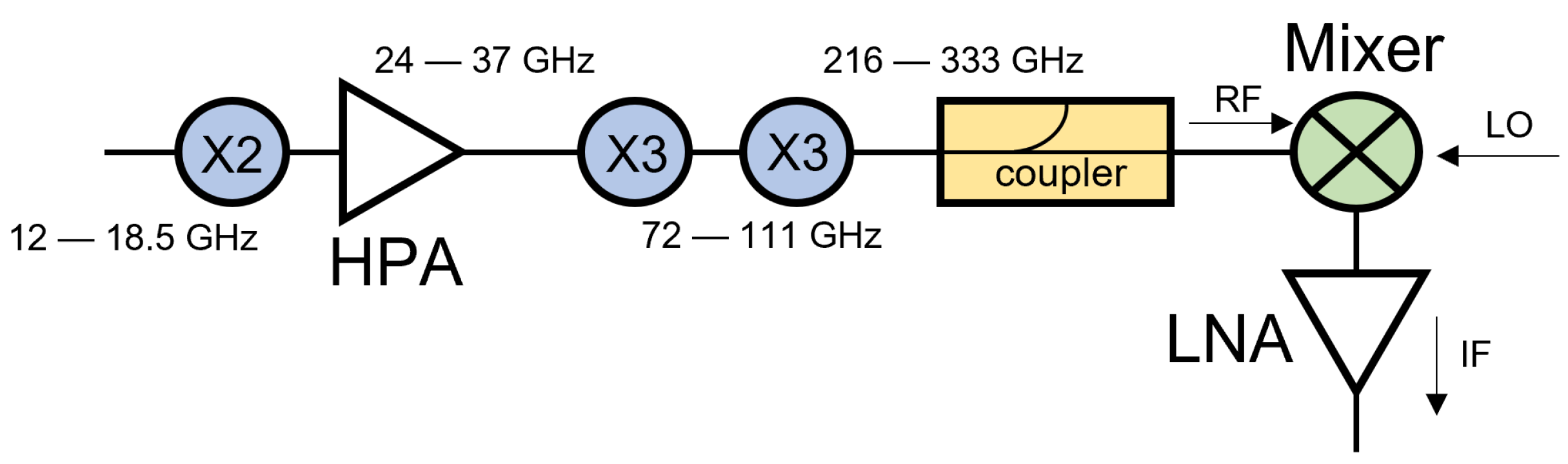
The experimental Local Oscillator chain used to measure Conversion Loss and Noise Figure for the traditional mixer is depicted in Figure 1. As Sub-Harmonic Mixers were compared in this study, the LO frequency was half of the RF. The chain was composed of a ×3 Amplifier Multiplier Chain (AMC) and two Schottky-based frequency doublers. Prior to the LO port of the mixer, a waveguide directional coupler was connected to a power meter, allowing real-time monitoring of the feeding power. The equivalent LO chain was used to measure the low-barrier mixer, adding a waveguide variable attenuator before the directional coupler, to reduce the LO power by 7–10 dB. The IF power was measured utilizing a Keysight N1913A Single-Channel power sensor head. To amplify the IF signal, an LNA was used directly before the power sensor head. In this study, we used an HD30161, a narrow band LNA that covered from 0.3 to 1.2 GHz. This LNA induced 0.7 dB of extra noise in the total noise of the receiver.
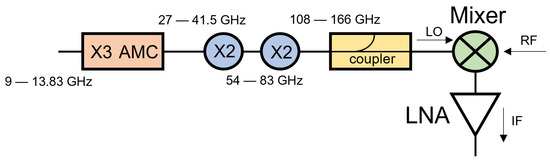
Figure 1.
The LocalOscillator chain used to feed the mixers in both the Conversion Loss and the Noise Figure measurements. In the low-barrier mixer measurements, a variable attenuator was placed between the coupler and the mixer LO port.
Figure 2 presents the RF chain used for the Conversion Loss measurements. It consisted of a doubler, a 32 dB gain High-Power Amplifier, and two high-power triplers in series. A waveguide directional coupler was again used to control the RF power feeding the mixer.
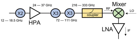
Figure 2.
The RF chain used in the Conversion Loss measurements.
We opted for these configurations due to ACST’s active development of high-frequency and high-power Active Multiplier Chains (AMCs) extending up to 1 THz. In our experimental setups, we harnessed two of our commercially available chains, to supply power to the mixer. It is important to note that achieving these frequencies could have been pursued through different methods. All the multipliers/mixers described in the block diagrams were fully designed, fabricated, and tested at ACST.
2.2. Conversion Loss and Power Requirement Measurements
The SSB Conversion Loss of the mixer was given by
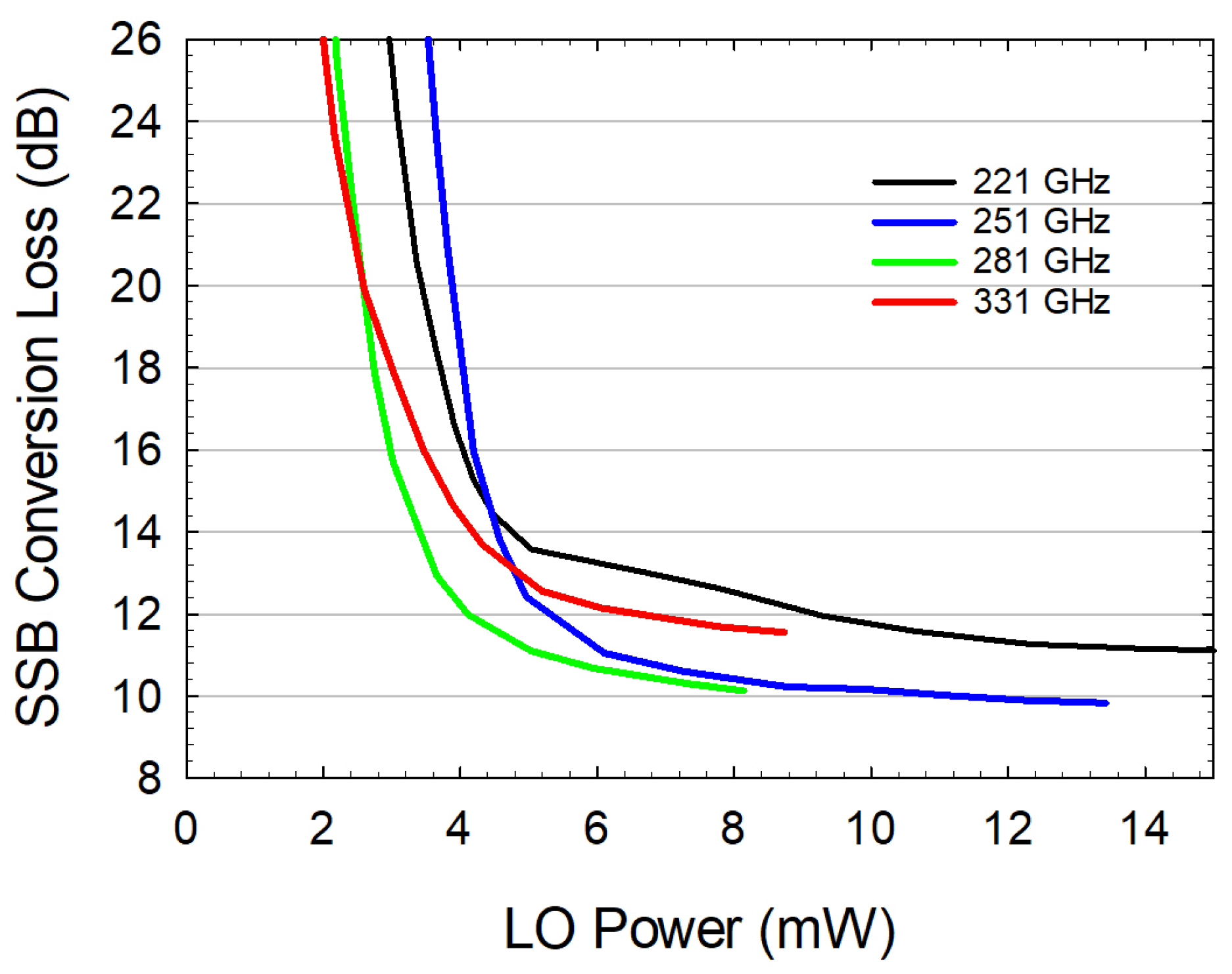
where was measured via a power meter and was controlled through a power sensor head. Figure 3 illustrates the experimental Single-Sideband (SSB) Conversion Loss obtained when varying the LO power levels during the testing of the GaAs-based mixer, which was conducted within a range from 2 to 14 mW. The results displayed in the plots indicate a distinct deviation between lower and upper frequencies. The deviation was attributed to the lack of power at higher frequencies, which drove a reduction in the required power levels during the design process. Notably, it can be observed that the plateau at all frequencies exhibited a flattened behavior beyond 6 mW, and that a constant was maintained beyond 14 mW. Hence, the mixer could be pumped without losing performance within a broad range of LO power. No risk of burning the diodes was taken during the measurements, due to the thermal dissipation technology that ACST developed years ago [23].
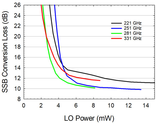
Figure 3.
GaAs-Based Mixer SSB Conversion Loss over Local Oscillator power. The measurements were taken with a constant IF of 1 GHz.
Due to the lack of LO power at 281 and 331 GHz, the analysis presented in Figure 3 could not go further than 8 mW in those frequency points. Nevertheless, uniform behavior is expected in such cases.
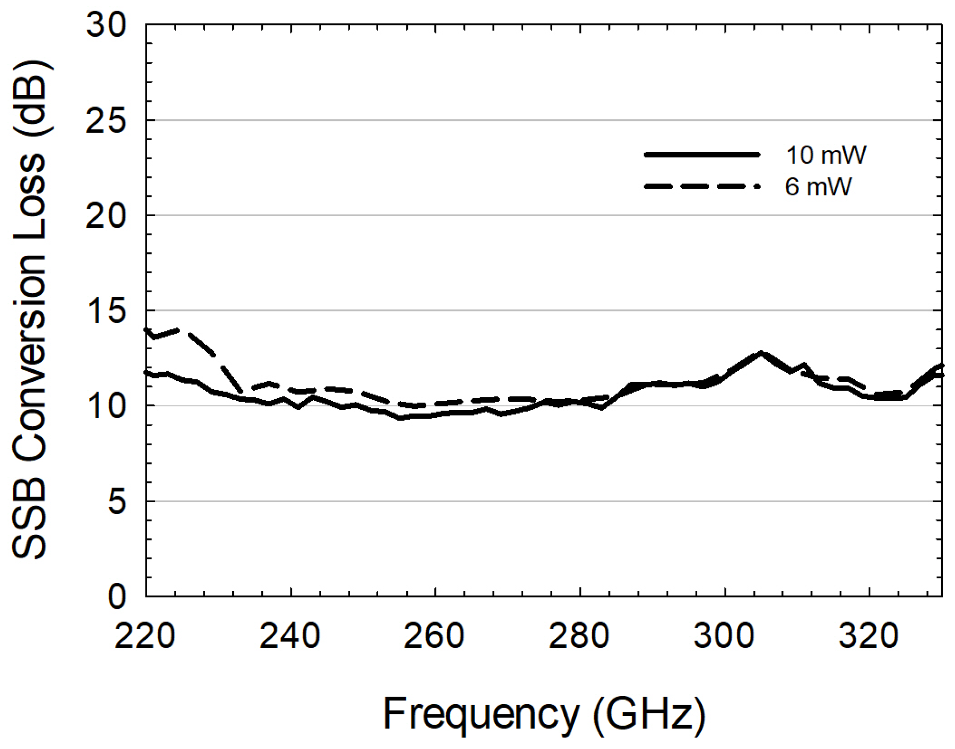
The SSB Conversion Loss of the mixer all over the RF band is presented in Figure 4. The measured results obtained at room temperatures by applying LO powers of 6 and 10 mW are compared. The SSB Conversion Loss within the 220 to 330 GHz band was analyzed, and the obtained results indicate a range of 12 to 9 dB CL at 10 mW and 15 to 10 dB CL at 6 mW. To address the power limitations encountered at higher frequencies, the mixer’s design was fine-tuned for optimal performance with lower LO powers in the high-frequency range. As illustrated in Figure 4, this design strategy led to a degradation in performance within the lower-frequency band when a 6 mW of LO power level was applied, retaining the same performance beyond 270 GHz. As illustrated in the plots, our findings demonstrate that a reduction in LO power only takes effect at lower frequencies, being consistent with the results shown in Figure 3.
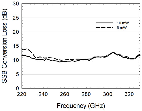
Figure 4.
GaAs-based Mixer SSB Conversion Loss applying 10 mW (solid line) and 6 mW (dashed line) fixed LO power. The measurements were obtained with a fixed IF frequency of 1 GHz.
Superior performance levels were observed at frequencies within the mid-band range compared to the edges of the spectrum. This phenomenon can be attributed to the design’s emphasis on achieving impedance matching at central frequencies. Consequently, deviations from these points led to increased impedance mismatching, resulting in a decrease in performance. The peak observed at 305 GHz can be attributed to unexpected resonances within the cavity, produced by unwanted harmonics.
2.3. Noise Temperature Measurements
Noise Temperature and Noise Figure measurements were carried out, following the so-called Y-factor method [24]. The selection of this methodology was based on its simplicity and ease of use. The Y-factor approach utilizes a noise source to determine the noise characteristics of a Device Under Test (DUT), which in our particular case was the mixer. The experimental setup implemented for the Local Oscillator chain is described in Figure 1. In this instance, an RF chain was not required; rather, a WR3.4 antenna was connected to the RF port of the mixer steering to the hot/cold load. Measuring the corresponding noise levels of the cold/hot sources, it was possible to calculate the Y-factor by the following formula [25]:
Being N the noise power (in dBm) measured for each load. Once the Y was obtained, (K) could be calculated, knowing the temperature of the loads. An absorber was used as a hot load; the measurement was taken at room temperature, so we assumed 293 K. For the cold load, liquid nitrogen was used for this purpose, with a 77 K constant boiling temperature. Knowing those data, the could be calculated, as follows [19]:
The Noise Figure of the mixer could be transformed by a direct relationship with the Noise Temperature, using the following equation [24]:
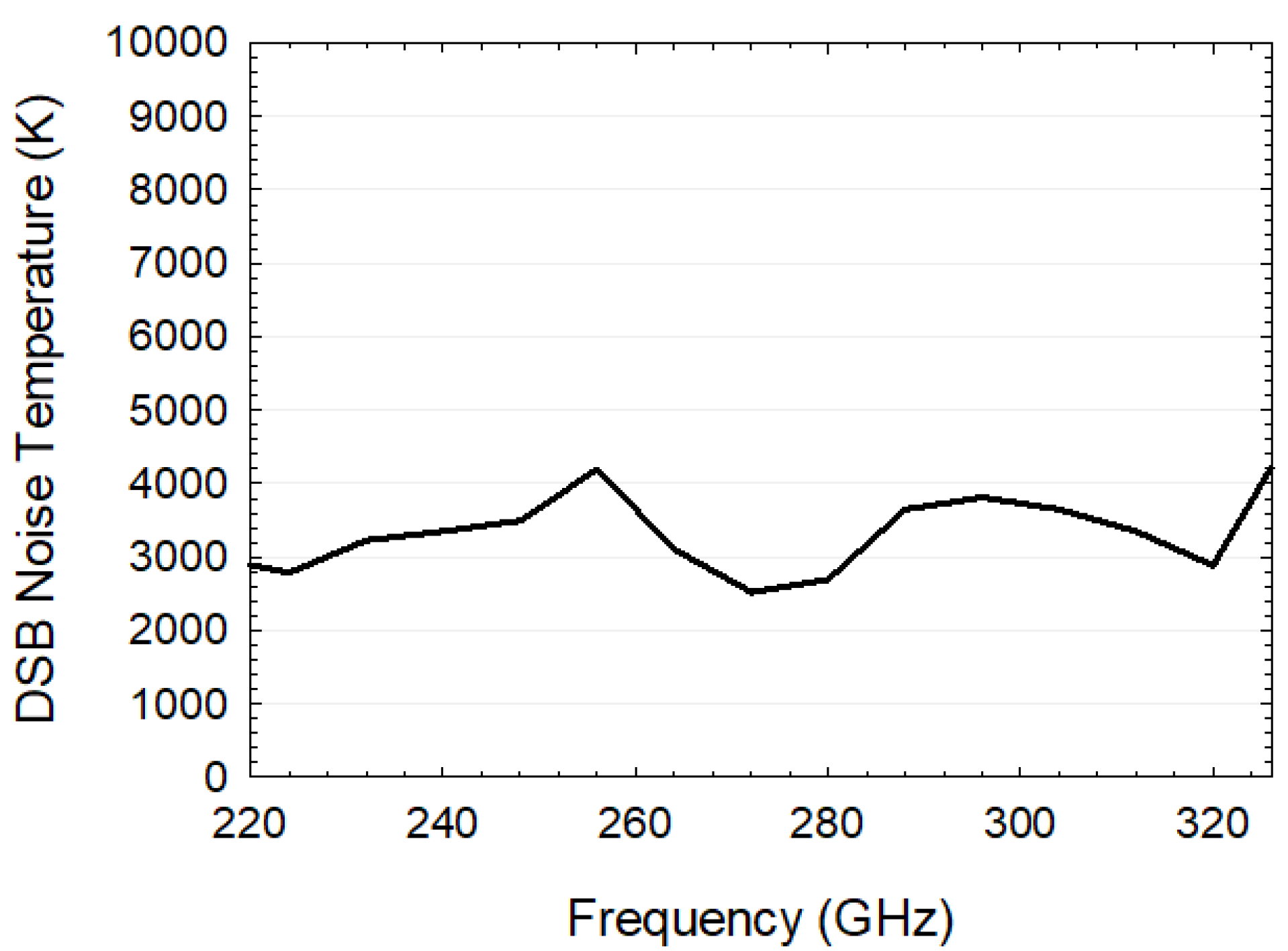
being the absolute temperature (290 K). The result of the DSB Noise Temperature is depicted in Figure 5. An average Noise Temperature of 3000 K was measured, performing minimum and maximum peaks of 2500 and 4200 K, respectively. In these measurements, the noise of the LNA was included, increasing the total noise of the receiver by 0.7 dB.
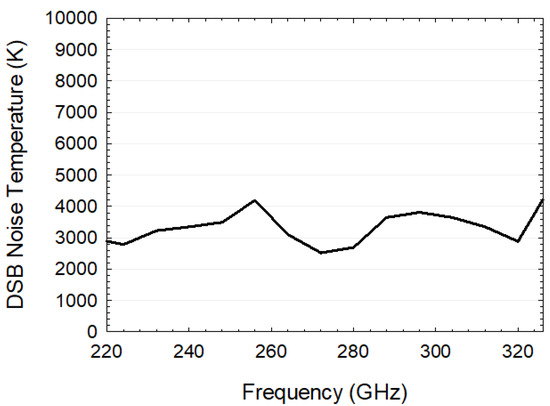
Figure 5.
GaAs-based Mixer DSB Noise Temperature with an input LO power of 6 mW. Fixed IF frequency at 1 GHz.
2.4. Simulations vs. Measurements
The optimization process and circuit design were performed using 3D electromagnetic modeling software and a non-linear electric circuit simulator (both version 2023). The electromagnetic properties of the diodes, filters, and antennas were solved in EMpro. The mixer structure was optimized using ADS Harmonic Balance simulations, to match the RF and LO signal impedance to the impedance of the diodes. This was achieved by an iterative process, using the S-parameters extracted from the EMpro simulations and the simulations results in ADS. To gain a more profound understanding of the application of harmonic balance simulations in mixer design and the utilization of EMpro, refs. [26,27] provide valuable insights into the theoretical foundations and practical implementations in such topics. In addition, a clear example of a mixer’s design process can be found in [13].
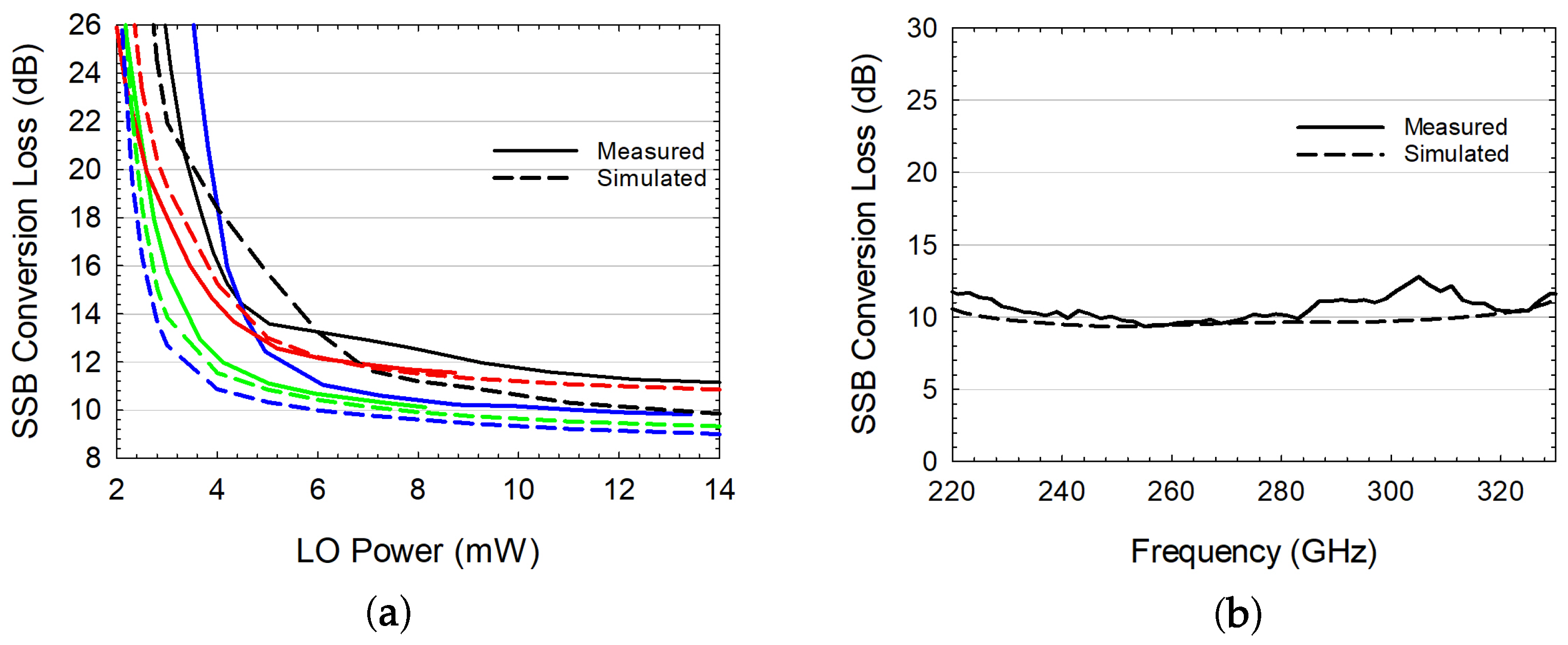
The mixer measured performance at room temperature is shown in Figure 6, together with the predicted results obtained in the ADS/EMpro simulations. A good agreement between simulations and measurements was obtained. Figure 6a shows the model prediction of Conversion Loss values at four frequency points while applying LO powers ranging from 2 to 14 mW. The simulations demonstrated a precise prediction of the behavior at each frequency when high powers were used (beyond 8 mW). However, according to the model, at 251 GHz (blue lines) the mixer Conversion Loss was expected to remain flat at 4 mW; nevertheless, in the actual measurements, it deteriorated when applying less than 6 mW. This constituted the only discrepancy observed between the model prediction and the experimental results.
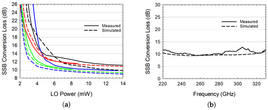
Figure 6.
(a) SSB CL over LO power comparison of the simulation and measurements—the black, blue, green, and red lines are 221, 251, 281, and 331 GHz, respectively; (b) SSB CL over the RF frequency comparison of the simulation and measurements.
Figure 6b compares the SSB Conversion Loss variation with respect to the RF frequency when a constant LO power of 10 mW was applied. The simulation indicated a constant response with a difference of 2 dB from maximum to minimum points. Any deviation observed in the experiments arose from imperfections during the manufacturing process, such as issues with bonding, diode assembly or blocking milling. Nevertheless, the simulation offered an accurate prediction of the overall performance.
3. Low-Barrier Mixer
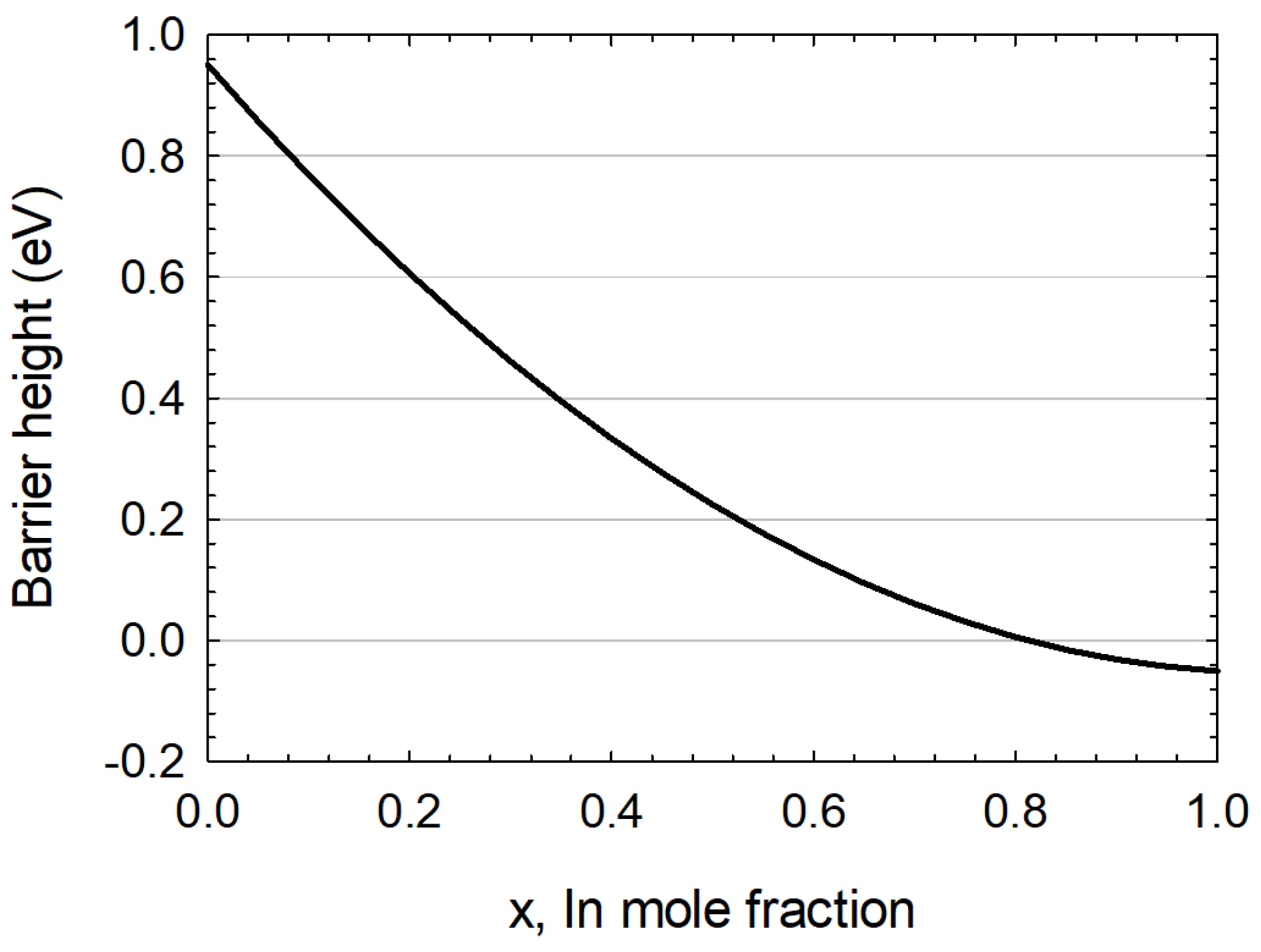
InGaAs diodes possess unique characteristics that make them highly desirable and well-suited for application in high-frequency mixers. Their primary advantage is attributed to the variable barrier height, which can be effectively controlled through the manipulation of the mole fraction of In, x in (5). This variation can result in a sweeping range of barrier heights between 0 and 1 eV, providing a broad spectrum of potential use cases for the diodes. The barrier height of an InGaAs diode as a function of the mole fraction is given by [28]:
As described in (5), Figure 7 plots how the addition of In to the diode epitaxy can result in a reduction of the barrier height, as low as 0 eV.
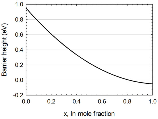
Figure 7.
Barrier height dependence of an InGaAs Schottky diode as a function of the mole fraction of In.
In addition to the benefits of InGaAs diodes in reducing the barrier height within the structure, two primary advantages of these diodes stand out: their superior bandgap and lattice matching characteristics. InGaAs diodes present lower bandgap energy than their GaAs counterparts (whose bandgap is 1.43 eV). This means that InGaAs Schottky diodes can be designed for lower-energy applications and can be sensitive to longer-wavelength light, such as infrared. The typical percentage of InGaAs is 53% In and 47% GaAs, giving a typical and well-known 0.75 eV value [29]. Furthermore, the mechanical characteristics of InGaAs can be tailored, by adjusting the In content within its chemical composition. In practical applications, InGaAs structures are commonly composed of approximately 53% In and 47% GaAs. This specific ratio is employed due to historical considerations: InGaAs is traditionally grown on InP substrates, and to achieve a compatible lattice constant with InP, these are the optimal proportions that minimize mechanical strain [30].
The performance of a full-band WR3.4 SHM featuring discrete InGaAs Schottky diodes is presented in the following sections.
3.1. Conversion Loss and Power Requirement Measurements
In the context of this study, it is important to note that the InGaAs wafer employed was primarily optimized for detector applications rather than mixers. Despite this usage mismatch, the advanced level of maturity achieved in diode technology enabled commendable results. The adeptness in diode technology effectively overcame the issue, highlighting both the adaptable nature of InGaAs as a material and the capacity to effectively exploit its potential across diverse applications.
The LO chain used during the measurements in this section was identical to the one illustrated in Figure 1, but with the addition of a WR6 waveguide variable attenuator between the last doubler and the coupler, in order to reduce the power to non-dangerous levels. Our simulations and technological insights indicate that a prudent upper limit for the input LO power applied to an InGaAs diode mixer is around 4 mW. This level of power is considered non-hazardous, and we recommend maintaining LO power levels below this threshold, to ensure safe and effective operation of the diodes.
As the RF was already small enough in both mixers, no changes in the RF chain were applied. RF power levels should ideally be maintained at a minimum of 10 times lower than that of the LO power. Given that we consistently applied a low and constant RF power of −20 dBm, it remained well below the LO power levels, ensuring that it did not adversely affect the overall performance.
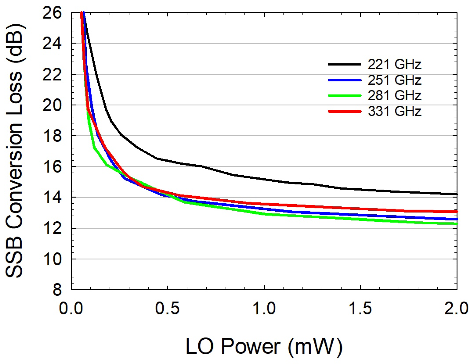
Figure 8 shows the SSB CL plotted against the levels of LO power. It can be seen that the plateau began at 0.5 mW, remaining stable beyond 2 mW, indicating the consistent behavior of the system. It can be observed in the plots that the mixer exhibited a uniform level of performance across all frequency points. Furthermore, the performance was as good as the State-of-the-Art of SHMs at 0.3 THz [14,31], even when the power was reduced to 0.3 mW.
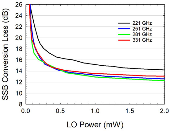
Figure 8.
InGaAs-Based Mixer SSB Conversion Loss over Local Oscillator power. Constant IF of 1 GHz was used.
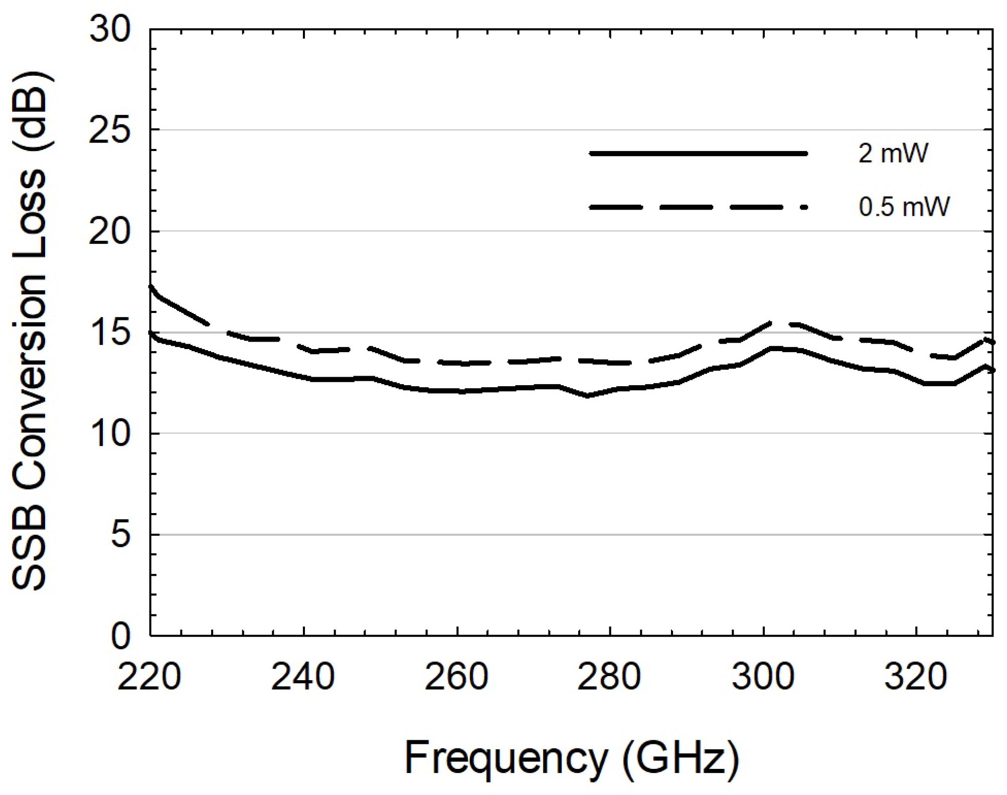
This performance is verified and plotted in Figure 9, which illustrates the SSB CL values across the RF band while applying two different LO powers. Similar to the previous mixer, an increase in power led to an enhanced performance. However, a reduction in power from 2 to 0.5 mW resulted in a CL increase of less than 2 dB. The overall shape of the curve remained constant in both scenarios, with a uniform flatness across the frequency range and a deviation of only 3 dB from maximum to minimum points.
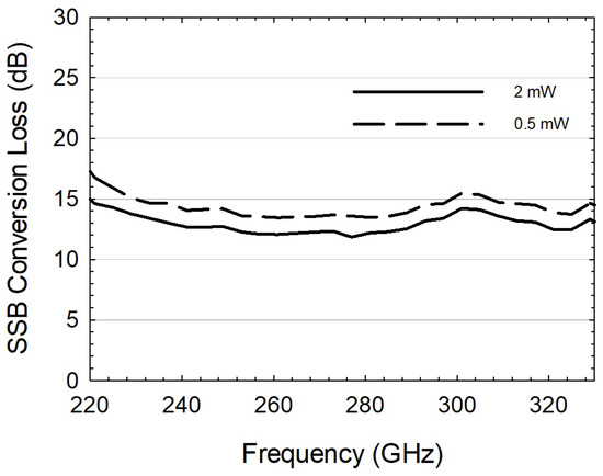
Figure 9.
InGaAs-based Mixer SSB Conversion Loss applying 2 mW (solid line) and 0.5 mW (dashed line) fixed LO power. The measurements were obtained with a fixed IF frequency of 1 GHz.
The reason behind this substantial enhancement became apparent upon closer examination. At the lower pump power of 0.5 mW, the mixer was operating in a suboptimal regime, far from its optimum operation point. Consequently, its performance was limited. However, by increasing the pump power to 2 mW, the mixer transitioned into the optimal operating region, and as a result, we observed a consistent and significant increase in performance.
3.2. Noise Temperature Measurements
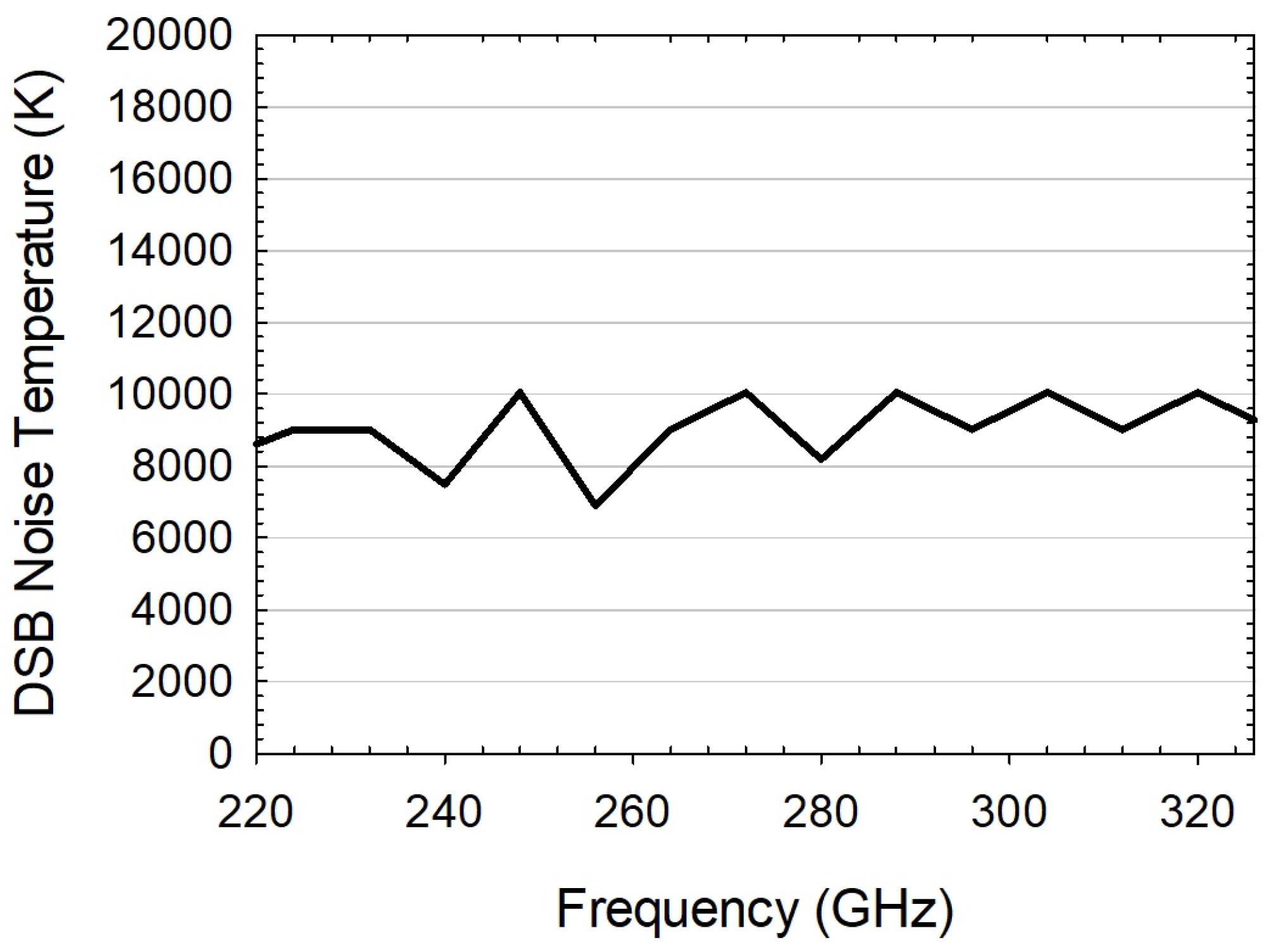
To determine the Noise Temperature of the second mixer, the Y-factor method was used again. The outcome of the DSB Noise Temperature measurement for the low-barrier mixer is presented in Figure 10. This measurement was performed utilizing an input LO power of 0.5 mW.
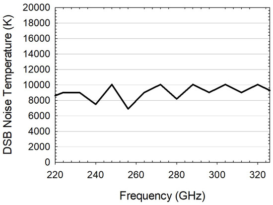
Figure 10.
InGaAs-based mixer DSB Noise Temperature.
On average, the mixer exhibited a stable response, of approximately 9000 K, with a minimum of 7000 K and a maximum of 10,000 K. The wavey behavior, the origination of which was due to the Y factor, was very small and hard to distinguish. The measurement incertitude had already induced such steps in the Noise Temperature.
3.3. Simulations vs. Measurements
A comparison between the simulation and measurement results was conducted, which involved the calculation of the main parameters that influenced the theoretical study, assuming that the capacitance of the low-barrier diodes was equivalent to the traditional diodes. The purpose of this comparison was to assess the accuracy of the theoretical models used to simulate the behavior of the low-barrier mixer. This analysis was important, to ensure that the theoretical models used in the design and optimization of the mixer were reliable and accurate.
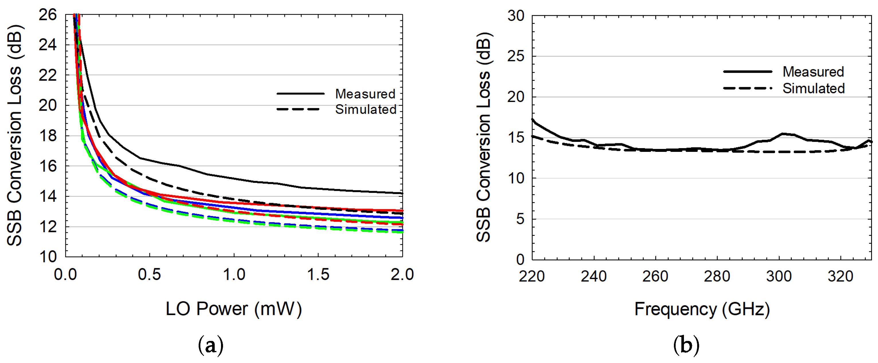
Figure 11a presents the outstanding agreement between simulation and measurements, both cases demonstrating minimum operative LO powers of 0.3 mW. The Conversion Loss was improved when the LO in increased even beyond 2 mW, showing a great range of operation. The difference between the Conversion Loss in the measurements and that obtained through simulations could be mitigated by adjusting the series resistance parameter in the diode model in ADS.
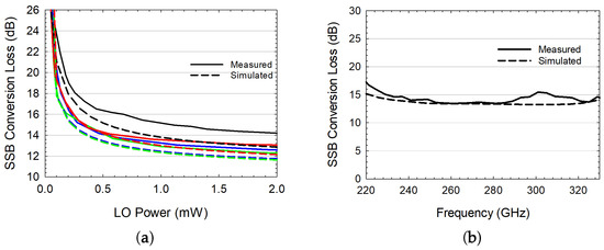
Figure 11.
Low-Barrier Mixer comparison between simulation and measurements: (a) SSB CL over LO power—the black, blue, green, and red lines are 221, 251, 281, and 331 GHz, respectively; (b) SSB CL over the RF frequency.
Figure 11b shows the SSB Conversion Loss over the RF band when using 0.5 mW of LO power for both simulation and measurements. As seen in earlier analyses, the simulation results closely matched the observed performance. This study shows that the diode model plays an important role in accurately predicting the mixer’s behavior, and it highlights the need for an appropriate modeling strategy.
4. GaAs and InGaAs Diode Mixer Performance Comparison
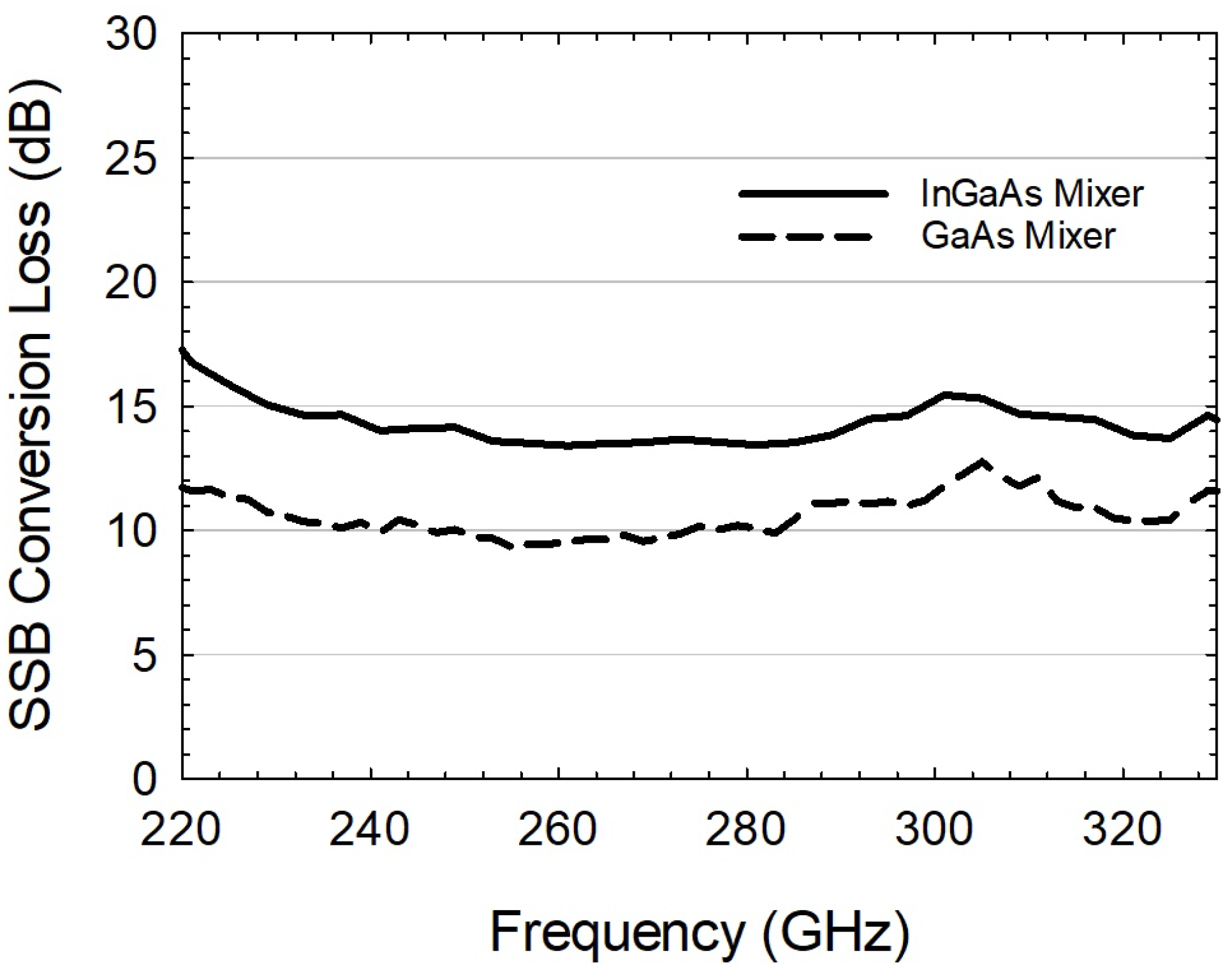
In this section, a comprehensive comparative analysis between mixers employing GaAs and InGaAs Schottky diodes is presented, focusing on the Conversion Loss and Noise Temperature performances. By closely examining the outcomes in these key performance indicators, we aimed to provide valuable insights into the practical advantages and potential trade-offs associated with these two mixer configurations. It is important to note that in the comparison, the GaAs mixer was driven by an input power of approximately 10 mW, while the InGaAs mixer operated with a significantly lower input power of 0.5 mW.
Figure 12 indicates that both mixers exhibited similar shape, in terms of SSB CL performances. Although the InGaAs mixer presented inferior results in 5 and 4 dB in the lower and upper regions of the RF band, respectively, it required considerably lower LO powers. Consequently, in scenarios where power consumption is a key concern, this low-barrier mixer can overcome this limitation, achieving high performances.
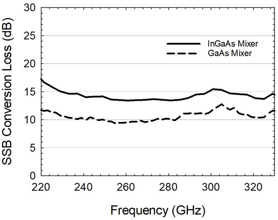
Figure 12.
Comparison of the CL SSB of the mixers, featuring InGaAs diodes (straight line) and GaAs diodes (dashed line).
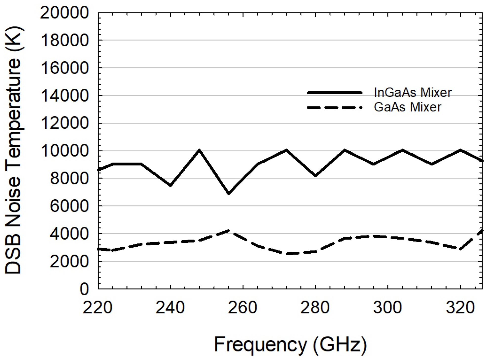
Comparison of the DSB Noise Temperature of the two mixers is presented in Figure 13. A difference between both graphs, of 4000–5000 K throughout the RF band, is clearly seen.
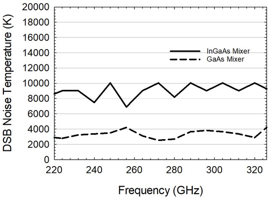
Figure 13.
DSB Noise Temperature comparison of the mixers with InGaAs diodes (straight line) and GaAs diodes (dashed line).
Within the context of this scientific investigation, it is imperative to underscore that both the mixers presented in this study demonstrated State-of-the-Art performance levels. Even when evaluating the InGaAs mixer, which exhibited comparatively lower performance, it remained on a par with the metrics outlined in Table 1. It is important to note that the mixers analyzed herein were full-band mixers and, generally, narrower frequency bands are associated with enhanced performances.
Despite the difference in performance, the measured values in both cases were suitable for a wide range of applications, where the selection of a particular mixer became an option based on the desired target, whether it be high performance or low power consumption.
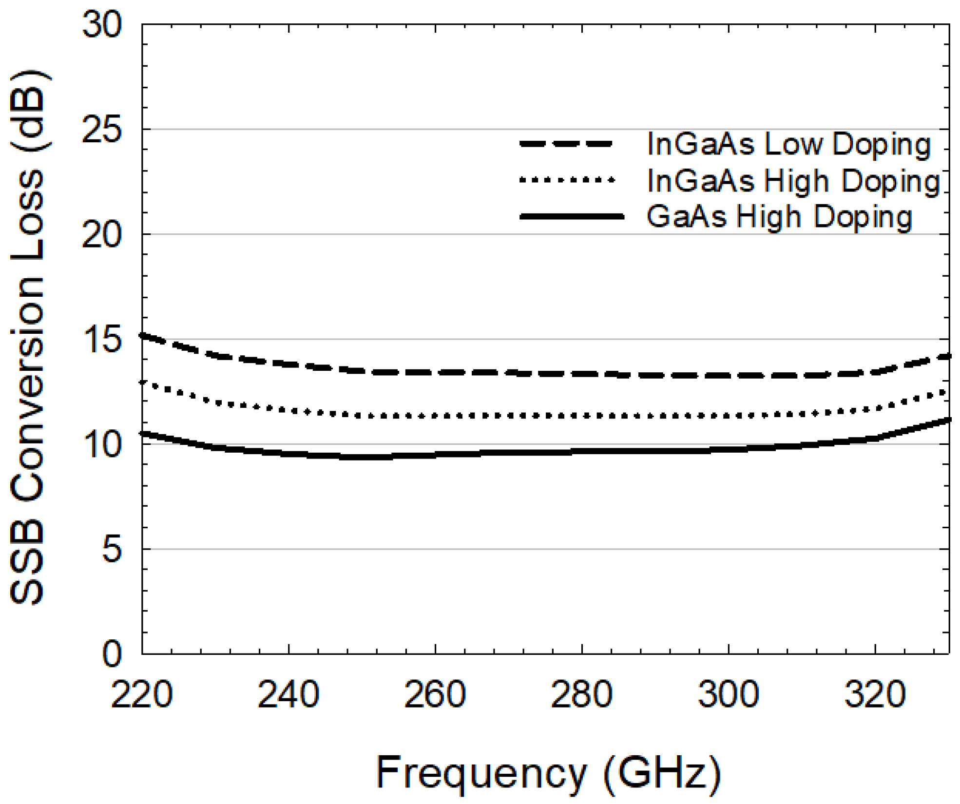
Notably, the results shown during the study strongly corroborate the superior capabilities of GaAs mixers over InGaAs, in terms of conversion loss performances. Nevertheless, according to our understanding and simulations, by strategically increasing the doping levels in the epilayer, InGaAs mixers can exhibit performance characteristics comparable to those of GaAs mixers. This highlights the possibility of enhancing InGaAs mixer performances, and thereby reducing the performance gap with GaAs counterparts. Figure 14 serves as a visual demonstration of our statement, providing a clear and concise representation of the simulated results.
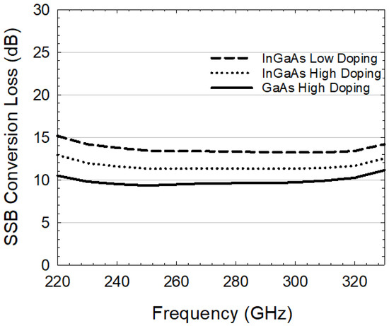
Figure 14.
Simulation performances of GaAs mixers using high-doped epitaxy versus InGaAs mixers using high- and low-doped epitaxies.
Figure 14 illustrates the potential to achieve equivalent efficiencies and reliability in InGaAs mixers under specific conditions modifying the doping of the structure. Figure 14 shows comprehensive insight into the distinct performances of three simulated mixers. The first mixer, employing GaAs diodes, emerged as the benchmark of efficiency, showcasing superior conversion characteristics. Positioned adjacent, the second mixer utilized InGaAs with a lower doping concentration, resulting in a reduced overall performance in comparison to the GaAs counterpart. However, the focal point of the illustration lies in the third mixer configuration. By leveraging InGaAs with a heightened doping level, the conversion loss was markedly reduced, and its efficiency approached the levels achieved by the GaAs mixer. In the near future, ACST is planning to fabricate a new batch of diodes with increased doping levels in the InGaAs epilayer, aiming to validate the simulation results. This experimental approach will further solidify the potential of InGaAs mixers to achieve performances comparable to GaAs. Combining simulations with real-world fabrication, our research seeks to advance the understanding of InGaAs technology’s capabilities in RF applications, creating opportunities to explore innovative mixer possibilities.
5. Conclusions
In summary, the first comparison between GaAs and InGaAs Schottky diodes in the same mixer structure has been shown, explaining the key insights into their performance characteristics and trade-offs. The GaAs mixer, while requiring a Local Oscillator power of 6–10 mW, exhibited State-of-the-Art performance metrics with a Conversion Loss of approximately 10 dB and a Noise Temperature of 3000 K. On the other hand, the InGaAs mixer stood out, with its remarkable advantage of consuming only 0.5 mW of Local Oscillator power, making it a compelling choice for power-sensitive applications. Despite this efficiency, it implied compromises in performance, featuring a Conversion Loss of around 14 dB and Noise Temperatures of 9000 K. In essence, the GaAs mixer showcased superior overall performance at the cost of higher power consumption, while the InGaAs mixer offered a balance between acceptable performance levels and minimal power requirements. This comparative study underscores the relationship between semiconductor selection, mixer performance, and power considerations, providing valuable insights for future THz applications. In the near future, ACST is planning to fabricate new InGaAs diodes with optimized epitaxial structures, in order to demonstrate their enhanced performances.
Author Contributions
The authors confirm contribution to the paper as follows: Conceptualization, J.M.G.; Methodology, A.N.; Validation, D.M.-M.; Investigation, J.M.G.; Resources, I.O.; Writing—original draft, J.M.G.; Writing—review & editing, J.M.G. and D.M.-M.; Supervision, D.M.-M.; Project administration, O.C.; Funding acquisition, O.C. All authors have read and agreed to the published version of the manuscript.
Funding
Horizon 2020 Marie Skodowska-Curie Actions TERAOPTICS (956857).
Conflicts of Interest
The authors declare no conflict of interest.
References
- Nagatsuma, T.; Fujita, Y.; Yasuda, Y.; Kanai, Y.; Hisatake, S.; Fujiwara, M.; Kani, J. Real-time 100-Gbit/s QPSK transmission using photonics-based 300-GHz-band wireless link. In Proceedings of the 2016 IEEE International Topical Meeting on Microwave Photonics (MWP), Long Beach, CA, USA, 31 October–3 November 2016; pp. 27–30. [Google Scholar]
- Hamada, H.; Fujimura, T.; Abdo, I.; Okada, K.; Song, H.-J.; Sugiyama, H.; Matsuzaki, H.; Nosaka, H. 300-GHz. 100-Gb/s InP-HEMT wireless transceiver using a 300-GHz fundamental mixer. In Proceedings of the 2018 IEEE/MTT-S International Microwave Symposium—IMS, Philadelphia, PA, USA, 10–15 June 2018; pp. 1480–1483. [Google Scholar]
- Chinni, V.K.; Latzel, P.; Zégaoui, M.; Coinon, C.; Wallart, X.; Peytavit, E.; Lampin, J.F.; Engenhardt, K.; Szriftgiser, P.; Zaknoune, M.; et al. Single-channel 100 Gbit/s transmission using III–V UTC-PDs for future IEEE 802.15.3d wireless links in the 300 GHz band. Electron. Lett. 2018, 54, 638–640. [Google Scholar] [CrossRef]
- Petrov, V.; Kurner, T.; Hosako, I. IEEE 802.15.3d: First Standardization Efforts for Sub-Terahertz Band Communications toward 6G. IEEE Commun. Mag. 2020, 58, 28–33. [Google Scholar] [CrossRef]
- Lee, S.; Hara, S.; Yoshida, T.; Amakawa, S.; Dong, R.; Kasamatsu, A.; Sato, J.; Fujishima, M. An 80-Gb/s 300-GHz-Band Single-Chip CMOS Transceiver. IEEE J.-Solid-State Circuits 2019, 54, 3577–3588. [Google Scholar] [CrossRef]
- Archer, J. Low-noise heterodyne receivers for near-millimeter-wave radio astronomy. Proc. IEEE 1985, 73, 109–130. [Google Scholar] [CrossRef]
- Blundell, R. Submillimeter receivers for radio astronomy. Proc. IEEE 1992, 80, 1702–1720. [Google Scholar] [CrossRef]
- Li, Y.; Zhang, Y.; Wu, C.; Cui, J.; Zhu, H.; Yan, B. A 16-QAM 45-Gbps 7-m wireless link using InP HEMT LNA and GaAs SBD mixers at 220-GHz-band. China Commun. 2021, 18, 255–262. [Google Scholar] [CrossRef]
- Melnick, G.J.; Stauffer, J.R.; Ashby, M.; Bergin, E.; Dalgarno, A.; Fazio, G.G.; Kleiner, S.; Plume, R.; Thaddeus, P.; Tolls, V.; et al. First Light Results from the Submillimeter Wave Astronomy Satellite. Am. Astron. Soc. 1998, 30, 1359. [Google Scholar]
- Makhlouf, S.; Cojocari, O.; Hofmann, M.; Nagatsuma, T.; Preu, S.; Weimann, N.; Hübers, H.; Stöhr, A. Terahertz Sources and Receivers: From the Past to the Future. IEEE J. Microw. 2023, 3, 894–912. [Google Scholar] [CrossRef]
- Adelseck, B.; Dieudonne, J.M.; Schmegner, K.E.; Colquhoun, A.; Ebert, G.; Selders, J. A monolithic 94 GHz balanced mixer. In Proceedings of the IEEE International Digest on Microwave Symposium, Dallas, TX, USA, 8–10 May 1990; pp. 111–114. [Google Scholar]
- Adelseck, B.; Colquhoun, A.; Dieudonne, J.M.; Ebert, G.; Selders, J.; Schmegner, K.E.; Schwab, W. A monolithic 60 GHz diode mixer in FET compatible technology. In Proceedings of the IEEE MTT-S International Microwave Symposium Digest, Long Beach, CA, USA, 13–15 June 1989; pp. 99–102. [Google Scholar]
- Kumari, S.; Mondal, P. Design of a subharmonic mixer for millimeter-wave applications. In Proceedings of the 2017 Progress in Electromagnetics Research Symposium-Fall (PIERS-FALL), Singapore, 19–22 November 2017; pp. 2727–2731. [Google Scholar]
- RPG Radiometer Physics GmbH, Fullband Subharmonic Mixers. Available online: https://www.radiometer-physics.de/products/mmwave-and-terahertz-products/mixers-subharmonic-and-harmonic-mixers/fullband-subharmonic-mixers (accessed on 31 March 2023).
- Liu, Y.; Zhang, B.; Feng, Y.; Lv, X.; Ji, D.; Niu, Z.; Yang, Y.; Zhao, X.; Fan, Y. Development of 340-GHz Transceiver Front End Based on GaAs Monolithic Integration Technology for THz Active Imaging Array. Appl. Sci. 2020, 10, 7924. [Google Scholar] [CrossRef]
- Niu, Z.; Zhang, B.; Fan, Y.; Zhang, L.S.; Xing, D.; Wang, J.L. The design of 850 GHz subharmonic mixer based on Schottky diodes. In Proceedings of the 2016 IEEE 9th UK-Europe-China Workshop on Millimetre Waves and Terahertz Technologies (UCMMT), Qingdao, China, 5–7 September 2016; pp. 89–91. [Google Scholar]
- Ji, D.F.; Zhang, B.; Zhang, L.; Xing, D.; Fan, Y. A 620–690 GHz sub-harmonic mixer based on monolithic GaAs integrated schottky diodes. In Proceedings of the 2017 International Applied Computational Electromagnetics Society Symposium (ACES), Suzhou, China, 1–4 August 2017; pp. 1–2. [Google Scholar]
- Shiba, S. Temperature Dependence of HEB Mixer Performance. In Proceedings of the 19th International Symposium on Space Terahertz Technology, Groningen, The Netherlands, 28–30 April 2008; pp. 59–61. [Google Scholar]
- Khanal, S.; Kiuru, T.; Hoefle, M.; Montero, J.; Cojocari, O.; Mallat, J.; Piironen, P.; Räisänen, A.V. Characterisation of low-barrier Schottky diodes for millimeter wave mixer applications. In Proceedings of the 2016 Global Symposium on Millimeter Waves (GSMM) & ESAWorkshop on Millimetre-Wave Technology and Applications, Espoo, Finland, 6–8 June 2016; pp. 1–4. [Google Scholar]
- Graziano, G.; Ferraris, A.; Cha, E.; Zota, C.B. The Effect of Cryogenic Temperatures on the Lateral Heat Spreading in InGaAs/InP HEMTs. IEEE Trans. Electron Devices 2023, 70, 4087–4092. [Google Scholar] [CrossRef]
- Hoefle, M.; Rickes, M.; Lain, V.; Moro, D.; Cojocari, O. Low Barrier Schottky Technology for MM and Sub-MM Wave Receiver Systems. In Proceedings of the 1st Space Microwave Week, Noordwijk, The Netherlans, 8–12 May 2023. [Google Scholar]
- Belio-Apaolaza, I.; Seddon, J.; Moro-Melgar, D.; Indiran, H.P.; Graham, C.; Balakier, K.; Cojocari, O.; Renaud, C.C. Photonically-driven Schottky diode based 0.3 THz heterodyne receiver. Opt. Express 2022, 30, 43223–43236. [Google Scholar] [CrossRef] [PubMed]
- Oprea, I.; Cojocari, O.; Sobornytskyy, M.; Hartnagel, H.L. Experimental validation of thermal model of MM-Wave frequency multipliers. In Proceedings of the 2013 38th International Conference on Infrared, Millimeter, and Terahertz Waves (IRMMW-THz), Mainz, Germany, 1–6 September 2013; pp. 1–2. [Google Scholar]
- Wong, K.; Wong, K.; Gorin, J.; Lu, G. Quantifying the error contribution of noise parameters on Y-factor noise figure measurements. In Proceedings of the 2017 89th ARFTG Microwave Measurement Conference (ARFTG), Honololu, HI, USA, 9 June 2017; pp. 1–9. [Google Scholar]
- Keysight Application Note 57-1, Fundamentals of RF and Microwave Noise Figure Measurement. Literature Number 5952-8255E. Available online: https://www.keysight.com/us/en/assets/7018-06808/application-notes/5952-8255.pdf (accessed on 31 March 2023).
- Keysight Technical Overview, Active Mixer Design—Chapter 10. Available online: https://www.keysight.com/us/en/assets/7018-05299/technical-overviews/5992-1634.pdf (accessed on 31 March 2023).
- Agilent Technologies, EMPro Quick Start-EMPro 2010. Available online: http://edadownload.software.keysight.com/eedl/empro/2010/pdf/quickstart.pdf (accessed on 31 March 2023).
- Brennan, T.A.; Mattauchi, R.J. The design and fabrication of In/sub x/Ga/sub 1-x/As Schottky barrier mixer diodes for space based heterodyne receivers. In Proceedings of the IEEE Proceedings of the SOUTHEASTCON ’91, Williamsburg, VA, USA, 7–10 April 1991; pp. 964–967. [Google Scholar]
- Takeda, Y.; Sasaki, A.; Imamura, Y.; Takagi, T. Electron mobility and energy gap of In0.53Ga0.47As on InP substrate. J. Appl. Phys. 1976, 47, 5405–5408. [Google Scholar] [CrossRef]
- Gelczuk, L.; Dabrowska-Szata, M.; Serafinczuk, J.; Motyka, M.; Misiewicz, J. Structural and optical measurements of residual strain and relaxation of lattice mismatched InGaAs/GaAs heterostructures. In Proceedings of the 2007 International Students and Young Scientists Workshop on Photonics and Microsystems, Dresden, Germany, 8–10 July 2007; pp. 23–26. [Google Scholar]
- Virginia Diodes, Inc. Mixers. Available online: https://www.vadiodes.com/en/products/mixers-shm-ehm-and-fm (accessed on 31 March 2023).

Disclaimer/Publisher’s Note: The statements, opinions and data contained in all publications are solely those of the individual author(s) and contributor(s) and not of MDPI and/or the editor(s). MDPI and/or the editor(s) disclaim responsibility for any injury to people or property resulting from any ideas, methods, instructions or products referred to in the content. |
© 2023 by the authors. Licensee MDPI, Basel, Switzerland. This article is an open access article distributed under the terms and conditions of the Creative Commons Attribution (CC BY) license (https://creativecommons.org/licenses/by/4.0/).