


Reviews Based on the Reconfigurable Intelligent Surface Technical Issues


Abstract
:1. Introduction
1.1. RIS History
1.2. RIS Introduction
2. Technical Considerations for RIS
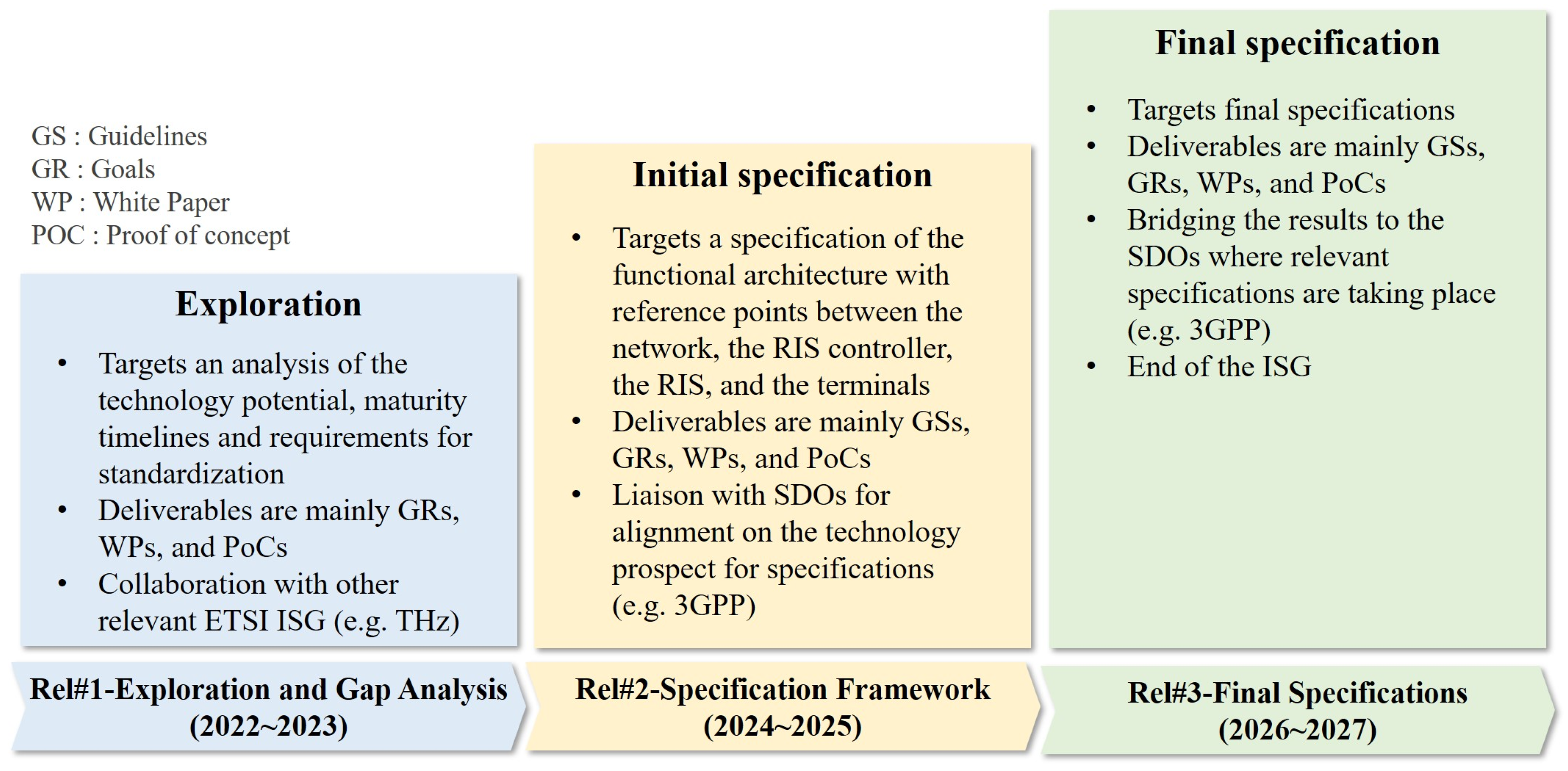
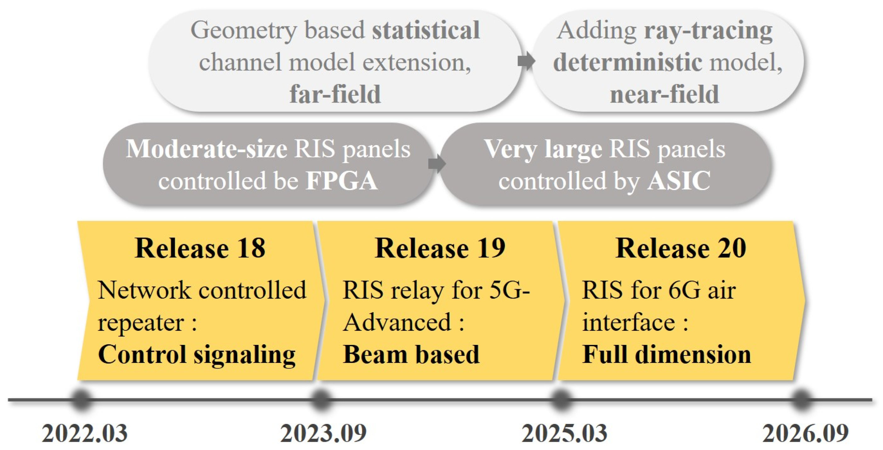
2.1. RIS Standardization
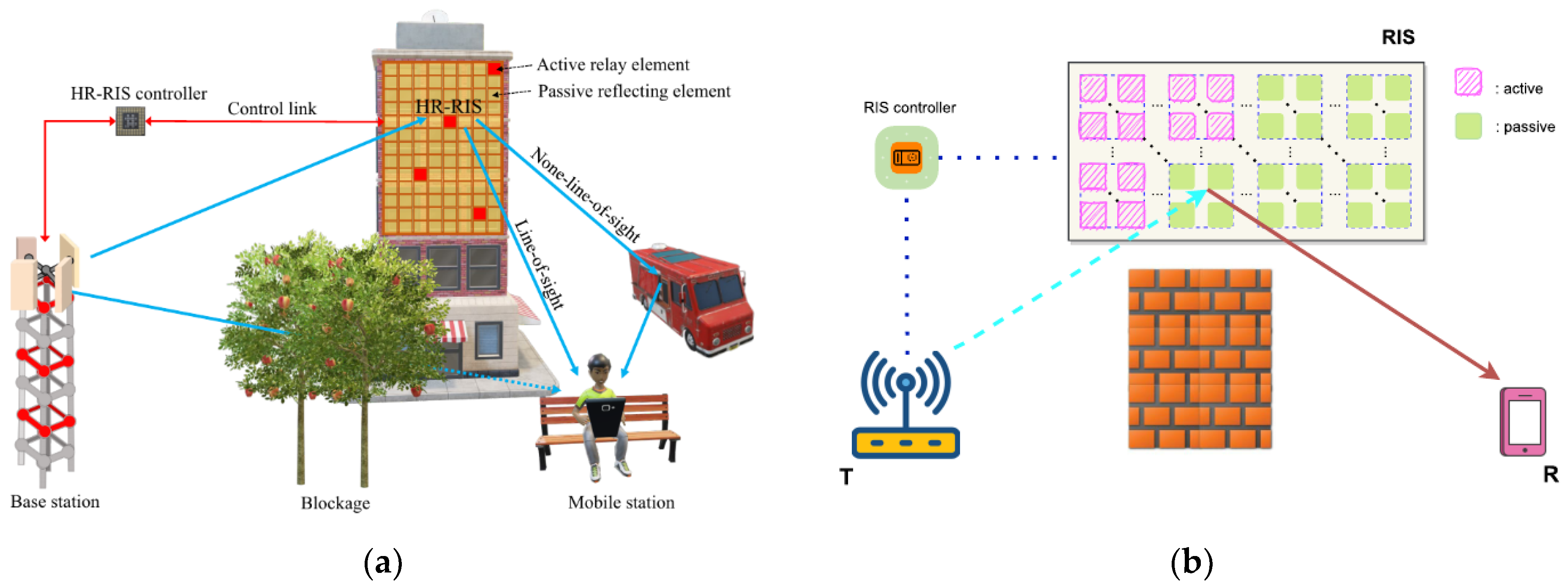
2.2. RIS Operation Modes and Types
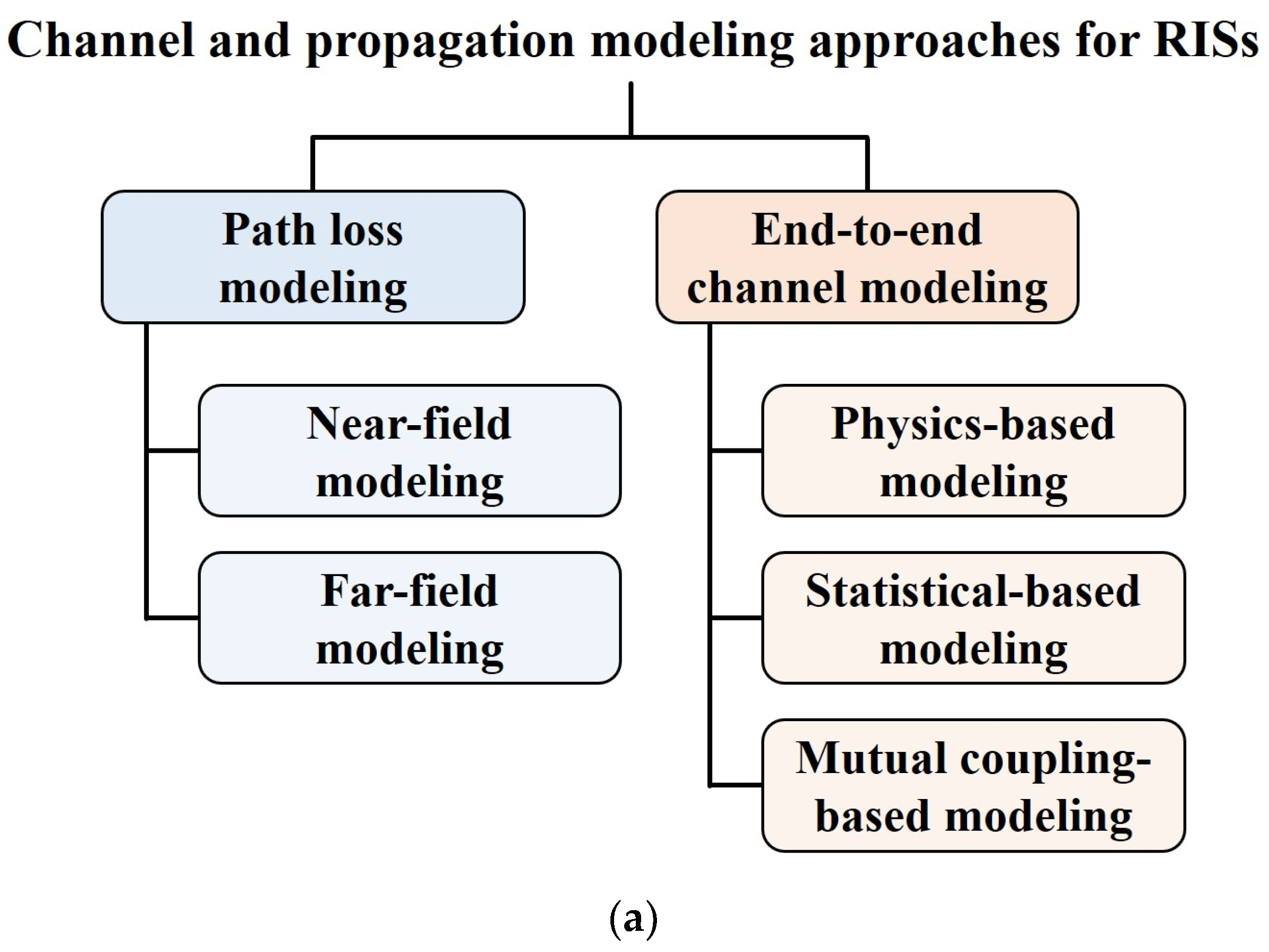
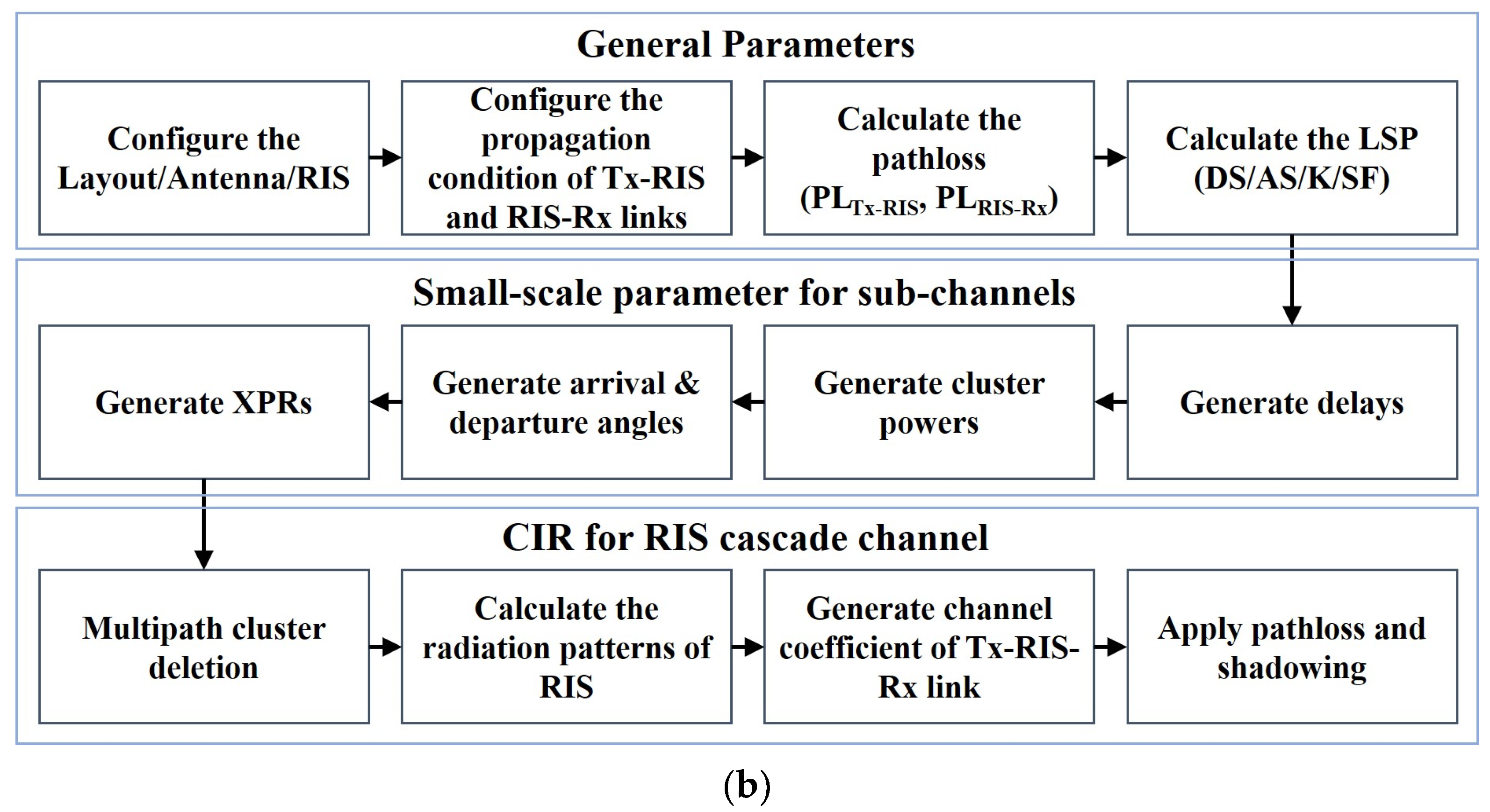
2.3. Channel Modeling

| Ref. | Abstract |
|---|---|
| [38] |
|
| [39] |
|
| [40] |
|
| [41] |
|
| [42] |
|
| [43] |
|
| [44] |
|
| [45] |
|
| [46] |
|
| [47,48] |
|
| [49,50,51] |
|
| [52] |
|
| [53] |
|
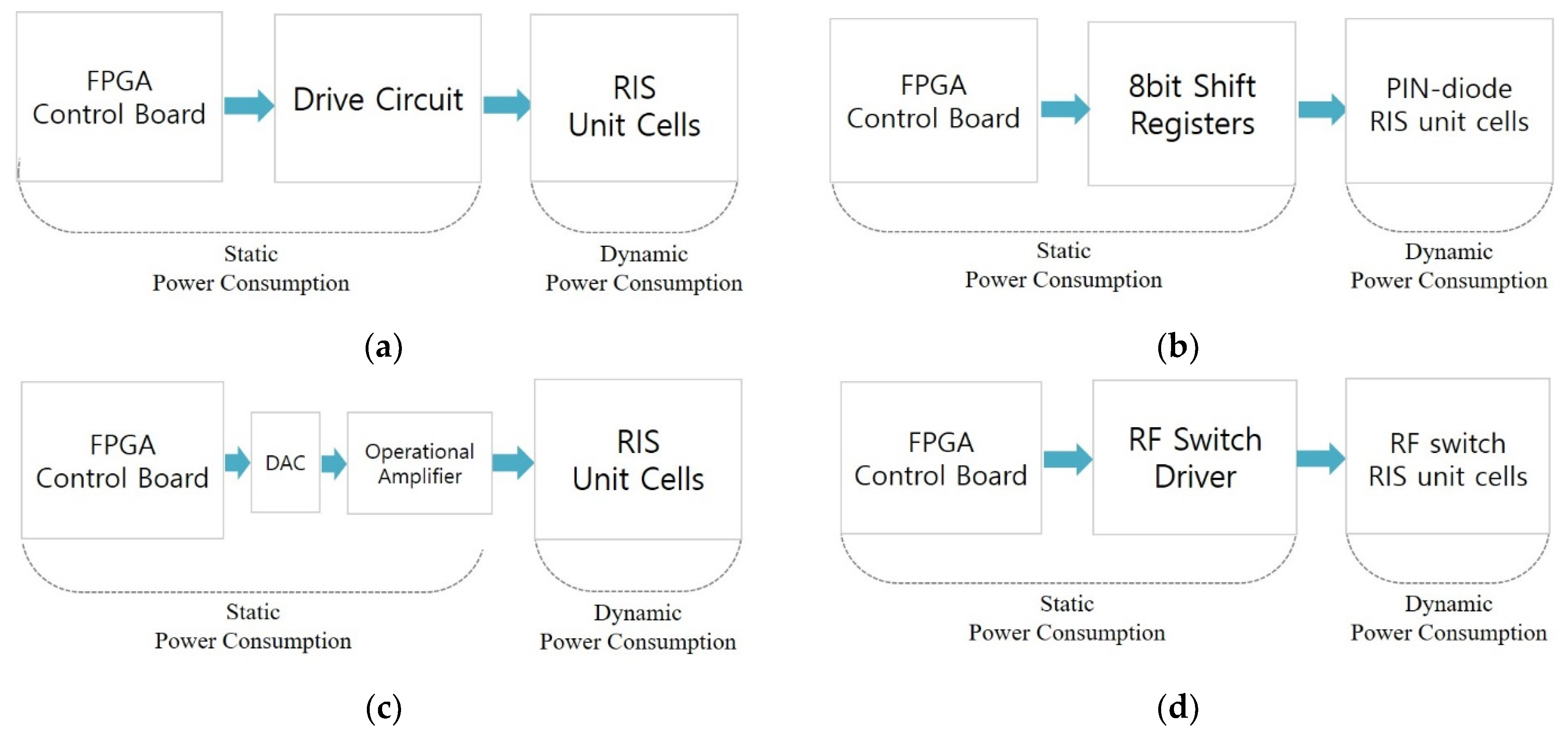
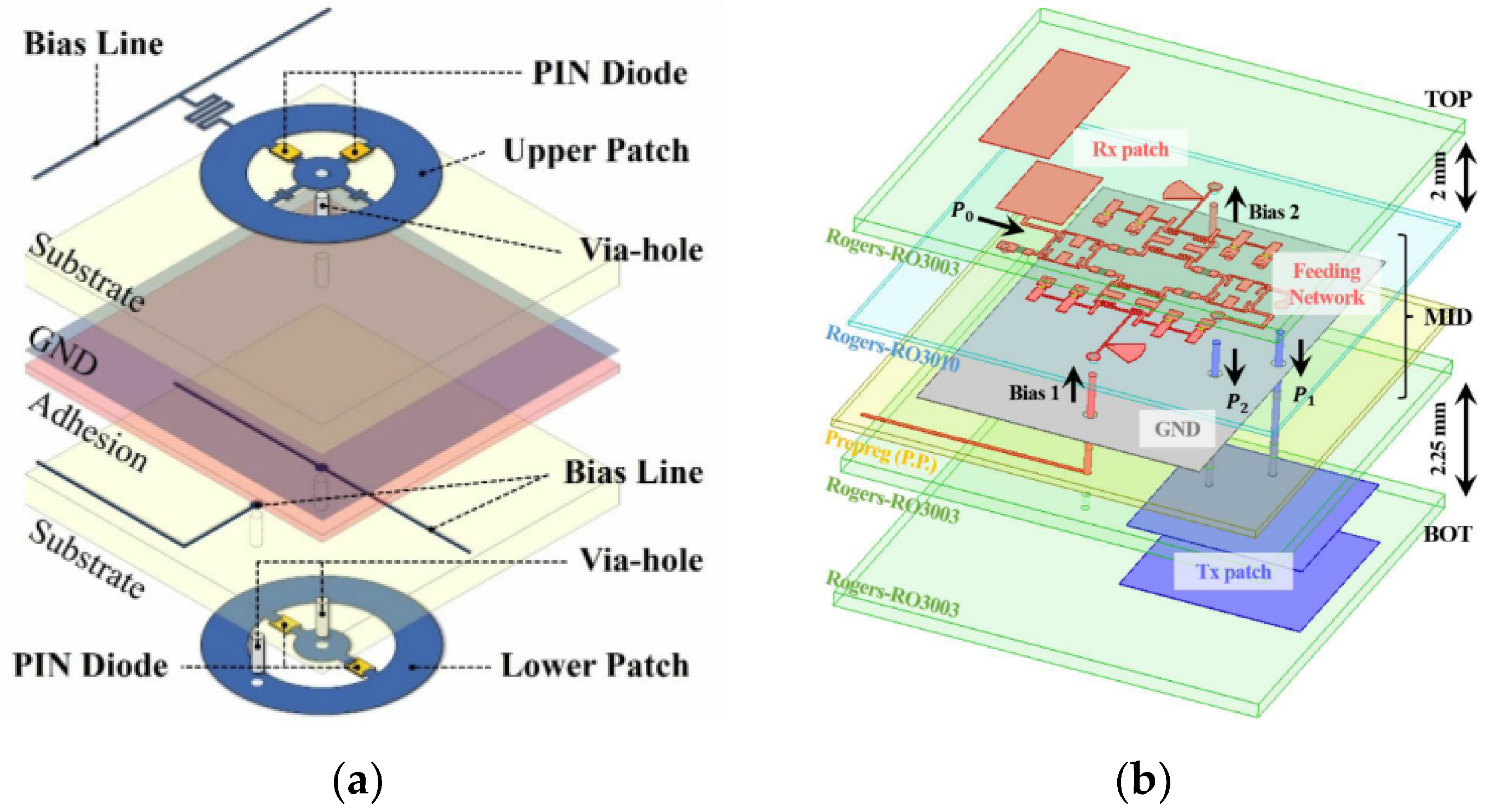
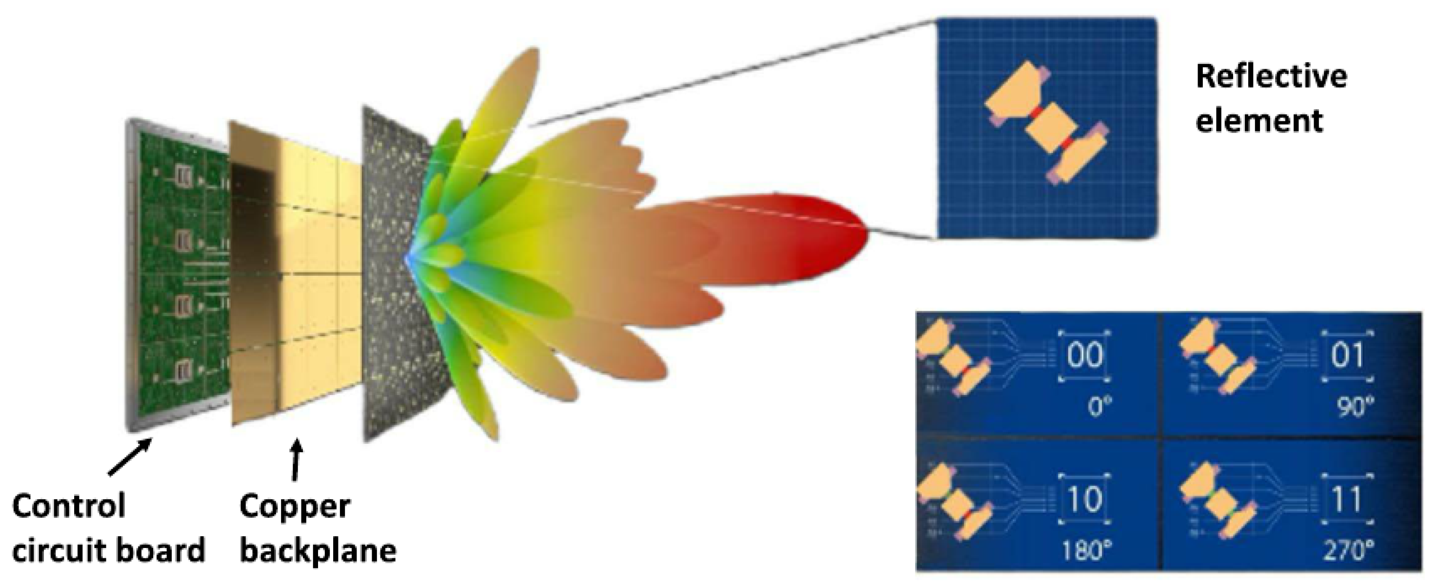
2.4. Hardware Implementation of RIS
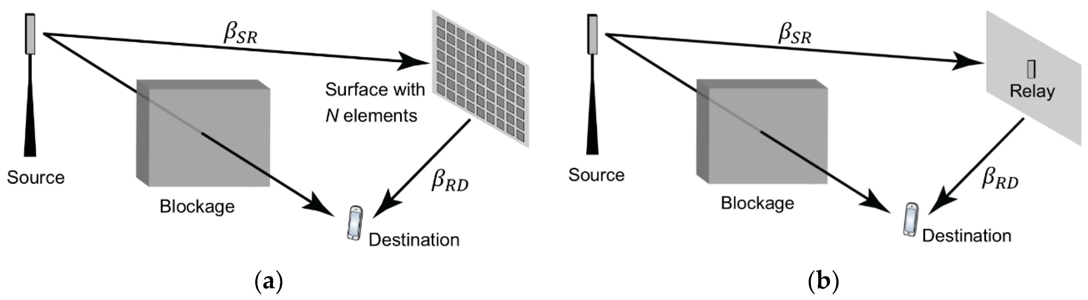
2.5. Differences between Relay and RIS [101]
2.6. Reflective/Transmissive RIS and Hybrid RIS
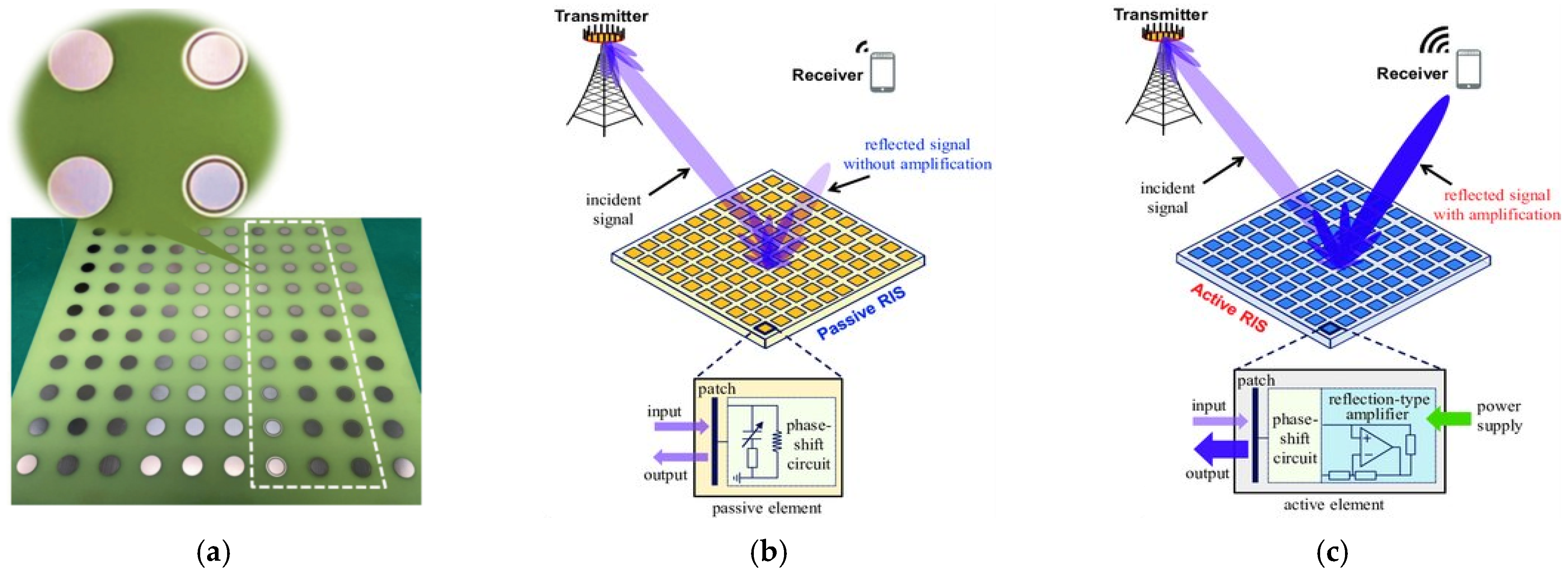
2.7. Passive, Active, and Hybrid RIS
2.8. Noise and Power in RIS
3. RIS Field Trials
3.1. RIS Performance Evaluation Parameters [28]
3.1.1. Rate/Throughput
3.1.2. Spectral Efficiency
3.1.3. Coverage
3.1.4. Energy Efficiency
- -
- Efficient data transfer under load: Efficient data transfer under load is characterized by spectral efficiency as defined above.
- -
- Low energy consumption in the absence of data: Low energy consumption in the absence of data can be estimated by the sleep ratio. The sleep ratio is the percentage of the time resource (in the case of a network) or sleep time (in the case of a device or RIS) that is unoccupied for a period corresponding to a control signal cycle (in the case of a network) or a discontinuous receive cycle (in the case of a device or an RIS) when no user data transmission occurs.
3.1.5. Secrecy Rate
3.2. Field Test Reviews
4. Conclusions
Funding
Data Availability Statement
Conflicts of Interest
References
- Liu, Y.; Liu, X.; Mu, X.; Hou, T.; Xu, J.; Di Renzo, M.; Al-Dhahir, N. Reconfigurable intelligent surfaces: Principles and opportunities. IEEE Commun. Surv. Tutor. 2021, 23, 1546–1577. [Google Scholar] [CrossRef]
- Wu, Q.; Zhang, R. Towards smart and reconfigurable environment: Intelligent reflecting surface aided wireless network. IEEE Commun. Mag. 2020, 58, 106–112. [Google Scholar] [CrossRef]
- Liaskos, C.; Nie, S.; Tsioliaridou, A.; Pitsillides, A.; Ioannidis, S.; Akyildiz, I. A new wireless communication paradigm through software-controlled metasurfaces. IEEE Commun. Mag. 2018, 56, 162–169. [Google Scholar] [CrossRef]
- Hu, S.; Rusek, F.; Edfors, O. Beyond massive MIMO: The potential of data transmission with large intelligent surfaces. IEEE Trans. Signal Process. 2018, 66, 2746–2758. [Google Scholar] [CrossRef]
- Glybovski, S.B.; Tretyakov, S.A.; Belov, P.A.; Kivshar, Y.S.; Simovski, C.R. Metasurfaces: From microwaves to visible. Phys. Rep. 2016, 634, 1–72. [Google Scholar] [CrossRef]
- Smith, D.R.; Pendry, J.B.; Wiltshire, M.C.K. Metamaterials and negative refractive index. Science 2004, 305, 788–792. [Google Scholar] [CrossRef]
- Hong, I.-P. Review of antenna technology using metasurfaces. Electromagn. Tech. KIEES 2022, 33, 20–53. [Google Scholar]
- Yu, N.F.; Genevet, P.; Kats, M.A.; Aieta, F.; Tetienne, J.P.; Capasso, F.; Gaburro, Z. Light propagation with phase discontinuities: Generalized laws of reflection and refraction. Science 2011, 334, 333–337. [Google Scholar] [CrossRef] [PubMed]
- Hu, J.; Bandyopadhyay, S.; Liu, Y.-h.; Shao, L.-y. A review on metasurface: From principle to smart metadevices. Front. Phys. 2021, 8, 586087. [Google Scholar] [CrossRef]
- Kamoda, H.; Iwasaki, T.; Tsumochi, J.; Kuki, T.; Hashimoto, O. 60-GHz electronically reconfigurable large reflectarray using single-bit phase shifters. IEEE Trans. Antennas Propag. 2011, 59, 2524–2531. [Google Scholar] [CrossRef]
- Cui, T.J.; Qi, M.Q.; Wan, X.; Zhao, J.; Cheng, Q. Coding metamaterials, digital metamaterials and programmable metamaterials. Light Sci. Appl. 2014, 3, e218. [Google Scholar] [CrossRef]
- Subrt, L.; Pechac, P. Controlling propagation environments using intelligent walls. In Proceedings of the 2012 6th European Conference on Antennas and Propagation (EUCAP), Prague, Czech Republic, 26–30 March 2012. [Google Scholar]
- Kaina, N.; Dupré, M.; Lerosey, G.; Fink, M. Shaping complex microwave fields in reverberating media with binary tunable metasurfaces. Sci. Rep. 2014, 4, 6693. [Google Scholar] [CrossRef]
- Yang, H.; Cao, X.; Yang, F.; Gao, J.; Xu, S.; Li, M.; Chen, X.; Zhao, Y.; Zheng, Y.; Li, S. A programmable metasurface with dynamic polarization, scattering and focusing control. Sci. Rep. 2016, 6, 35692. [Google Scholar] [CrossRef] [PubMed]
- Tan, X.; Sun, Z.; Jornet, J.M.; Pados, D. Increasing indoor spectrum sharing capacity using smart reflect-array. In Proceedings of the 2016 IEEE International Conference on Communications (ICC), Kuala Lumpur, Malaysia, 22–27 May 2016. [Google Scholar]
- Renzo, M.D.; Debbah, M.; Phan-Huy, D.-T.; Zappone, A.; Alouini, M.-S.; Yuen, C.; Sciancalepore, V.; Alexandropoulos, G.C.; Hoydis, J.; Gacanin, H.; et al. Smart radio environments empowered by reconfigurable ai meta-surfaces: An idea whose time has come. EURASIP J. Wirel. Commun. Netw. 2019, 129, 1–20. [Google Scholar] [CrossRef]
- Liu, R. Key use cases and latest progress in prototyping, testing & standardization of RIS. In Proceedings of the IEEE Global Communications Conference, Madrid, Spain, 7–11 December 2021. [Google Scholar]
- Jian, M.; Liu, R.; Chen, Y. Standardization for reconfigurable intelligent surfaces: Progresses, challenges and the road ahead. In Proceedings of the 2021 IEEE/CIC International Conference on Communications in China (ICCC Workshops), Xiamen, China, 28–30 July 2021. [Google Scholar]
- Jiang, M.; Cezanne, J.; Sampath, A.; Shental, O.; Wu, Q.; Koymen, O.; Bedewy, A.; Li, J. Wireless fronthaul for 5G and future radio access networks: Challenges and enabling technologies. IEEE Wirel. Commun. 2022, 29, 108–114. [Google Scholar] [CrossRef]
- Wu, Q.; Zhang, S.; Zheng, B.; You, C.; Zhang, R. Intelligent reflecting surface-aided wireless communications: A tutorial. IEEE Trans. Commun. 2021, 69, 3313–3351. [Google Scholar] [CrossRef]
- Björnson, E.; Özdogan, Ö.; Larsson, E.G. Reconfigurable intelligent surfaces: Three myths and two critical questions. IEEE Commun. Mag. 2020, 58, 90–96. [Google Scholar] [CrossRef]
- Liu, R.; Alexandropoulos, G.C.; Wu, Q.; Jian, M.; Liu, Y. How can reconfigurable intelligent surfaces drive 5G-advanced wireless networks: A standardization perspective. In Proceedings of the 2022 IEEE/CIC International Conference on Communications in China (ICCC Workshops), Foshan, China, 11–13 August 2022. [Google Scholar]
- Liu, R.; Wu, Q.; Di Renzo, M.; Yuan, Y. A path to smart radio environments: An industrial viewpoint on reconfigurable intelligent surfaces. IEEE Wirel. Commun. 2022, 29, 202–208. [Google Scholar] [CrossRef]
- IEEE Communications Society Reconfigurable Intelligent Surfaces Emerging Technology Initiative—Reconfigurable Intelligent Surfaces Emerging Technology Initiative. Available online: https://riseti.committees.comsoc.org/ (accessed on 8 October 2023).
- IEEE COMSOC WTC SIG RISE. Available online: https://sites.google.com/view/ieee-comsoc-wtc-sig-rise (accessed on 8 October 2023).
- SIG on REconFigurabLE Intelligent Surfaces for Signal Processing and CommunicatIONS (REFLECTIONS)—IEEE Communications Society Signal Processing and Computing for Communications Technical Committee. Available online: https://spcc.committees.comsoc.org/special-interest-groups/sig-reflections/ (accessed on 8 October 2023).
- ETSI—Our Group Reconfigurable Intelligent Surface (RIS). Available online: https://www.etsi.org/committee/1966-ris (accessed on 8 October 2023).
- ETSI GR RIS 003(V1.1.1). Reconfigurable Intelligent Surfaces (RIS); Communication Models, Channel Models, Channel Estimation and Evaluation Methodology. June 2023. Available online: https://www.etsi.org/deliver/etsi_gr/RIS/001_099/003/01.01.01_60/gr_RIS003v010101p.pdf (accessed on 8 October 2023).
- China Communications Standards Association. Meeting Detail of TC5 WG6 Meeting 55. September 2020. Available online: https://www.ccsa.org.cn/meetingDetail/?id=91&title=TC5WG6%E7%AC%AC55%E6%AC%A1%E5%B7%A5%E4%BD%9C%E7%BB%84%E4%BC%9A%E8%AE%AE (accessed on 8 October 2023).
- FuTURE Forum|Home. Available online: http://www.future-forum.org.cn/en/index.asp (accessed on 8 October 2023).
- Report ITU-R M.2516-0. Future Technology Trends of Terrestrial IMT Systems towards 2030 and beyond. November 2022. p. 93. Available online: https://www.itu.int/dms_pub/itu-r/oth/0a/0e/R0A0E0000E80001PDFE.pdf (accessed on 8 October 2023).
- Yuan, Y.; Wu, D.; Huang, Y.; I, C.-L. Reconfigurable intelligent surface relay: Lessons of the past and strategies for its success. IEEE Commun. Mag. 2022, 60, 117–123. [Google Scholar] [CrossRef]
- ZTE Corporation, Sanechips. Support of Reconfigurable Intelligent Surface For 5G Advanced. March 2021. Available online: https://www.3gpp.org/ftp/TSG_RAN/TSG_RAN/TSGR_91e/Docs/RP-210618.zip (accessed on 8 October 2023).
- ETSI GR RIS 001(V1.1.1). Reconfigurable Intelligent Surfaces (RIS); Use Cases, Deployment Scenarios and Requirements. April 2023. Available online: https://etsi.org/deliver/etsi_gr/RIS/001_099/001/01.01.01_60/gr_RIS001v010101p.pdf (accessed on 8 October 2023).
- Huang, J.; Wang, C.X.; Sun, Y.; Feng, R.; Huang, J.; Guo, B.; Zhong, Z.; Cui, T.J. Reconfigurable intelligent surfaces: Channel characterization and modeling. Proc. IEEE 2022, 110, 1290–1311. [Google Scholar] [CrossRef]
- ETSI TR 138 901 (V16.1.0). 5G; Study on Channel Model for Frequencies from 0.5 to 100 GHz (3GPP TR 38.901 Version 16.1.0 Release 16). November 2022. Available online: https://www.etsi.org/deliver/etsi_tr/138900_138999/138901/16.01.00_60/tr_138901v160100p.pdf (accessed on 8 October 2023).
- Yildirim, I.; Basar, E. Channel modelling in RIS-empowered wireless communications. In Intelligent Reconfigurable Surfaces (IRS) for Prospective 6G Wireless Networks; Wiley: Hoboken, NJ, USA, 2022; pp. 123–148. [Google Scholar] [CrossRef]
- Di Renzo, M.; Danufane, F.H.; Xi, X.; De Rosny, J.; Tretyakov, S. Analytical modeling of the path-loss for reconfigurable intelligent surfaces—Anomalous mirror or scatterer? In Proceedings of the 2020 IEEE 21st International Workshop on Signal Processing Advances in Wireless Communications (SPAWC), Atlanta, GA, USA, 26–29 May 2020.
- Bartoli, G.; Abrardo, A.; Decarli, N.; Dardari, D.; Di Renzo, M. Spatial multiplexing in near field MIMO channels with reconfigurable intelligent surfaces. IET Signal Process. 2023, 17, e12195. [Google Scholar] [CrossRef]
- Ellingson, S.W. Path loss in reconfigurable intelligent surface-enabled channels. In Proceedings of the 2021 IEEE 32nd Annual International Symposium on Personal, Indoor and Mobile Radio Communications (PIMRC), Helsinki, Finland, 13–16 September 2021. [Google Scholar]
- Özdogan, Ö.; Björnson, E.; Larsson, E.G. Intelligent reflecting surfaces: Physics, propagation, and pathloss modeling. IEEE Wirel. Commun. Lett. 2019, 9, 581–585. [Google Scholar] [CrossRef]
- Tang, W.; Chen, M.; Chen, X. Wireless communications with reconfigurable intelligent surface: Path loss modeling and experimental measurement. IEEE Trans. Wirel. Commun. 2021, 20, 421–439. [Google Scholar] [CrossRef]
- Danufane, F.H.; Renzo, M.; de Rosny, J.; Tretyakov, S. On the path-loss of reconfigurable intelligent surfaces: An approach based on green’s theorem applied to vector fields. IEEE Trans. Commun. 2021, 69, 5573–5592. [Google Scholar] [CrossRef]
- Björnson, E.; Sanguinetti, L. Power scaling laws and near-field behaviors of massive MIMO and intelligent reflecting surfaces. IEEE Open J. Commun. Soc. 2020, 1, 1306–1324. [Google Scholar] [CrossRef]
- Zhi, K.; Pan, C.; Ren, H.; Wang, K. Power scaling law analysis and phase shift optimization of RIS-aided massive MIMO systems with statistical CSI. IEEE Trans. Commun. 2022, 70, 3558–3574. [Google Scholar] [CrossRef]
- Gradoni, G.; Di Renzo, M. End-to-end mutual coupling aware communication model for reconfigurable intelligent surfaces: An electromagnetic-compliant approach based on mutual impedances. IEEE Wirel. Commun. Lett. 2021, 10, 938–942. [Google Scholar] [CrossRef]
- Sun, Y.; Wang, C.; Huang, J.; Wang, J. A 3D non-stationary channel model for 6G wireless systems employing intelligent reflecting surfaces with practical phase shifts. IEEE Trans. Cogn. Commun. Netw. 2021, 7, 496–510. [Google Scholar] [CrossRef]
- Jiang, H.; Ruan, C.; Zhang, Z.; Dang, J.; Wu, L.; Mukherjee, M.; da Costa, D.B. A general wideband non-stationary stochastic channel model for intelligent reflecting surface-assisted MIMO communications. IEEE Trans. Wirel. Commun. 2021, 20, 5314–5328. [Google Scholar] [CrossRef]
- Basar, E.; Yildirim, I. Reconfigurable intelligent surfaces for future wireless networks: A channel modeling perspective. IEEE Wirel. Commun. 2021, 28, 108–114. [Google Scholar] [CrossRef]
- Basar, E.; Yildirim, I.; Kilinc, F. Indoor and outdoor physical channel modeling and efficient positioning for reconfigurable intelligent surfaces in mmWave bands. IEEE Trans. Commun. 2021, 69, 8600–8611. [Google Scholar] [CrossRef]
- Kilinc, F.; Yildirim, I.; Basar, E. Physical channel modeling for RIS-empowered wireless networks in sub-6 GHz bands. In Proceedings of the 2021 55th Asilomar Conference on Signals, Systems, and Computers, Pacific Grove, CA, USA, 31 October–3 November 2021. [Google Scholar]
- Faqiri, R.; Saigre-Tardif, C.; Alexandropoulos, G.C.; Shlezinger, N.; Imani, M.F.; Del Hougne, P. PhysFad: Physics-based end-to-end channel modeling of RIS-parametrized environments with adjustable fading. IEEE Trans. Wirel. Commun. 2022, 22, 580–595. [Google Scholar] [CrossRef]
- Van Tuan, P.; Hong, I.P. IRS-aided wireless communication: From physics to channel modeling and characterization. IEEE Access 2023, 11, 3184–3197. [Google Scholar] [CrossRef]
- Gong, H.; Zhang, J.; Zhang, Y.; Zhou, Z.; Pan, J.; Liu, G. How to Extend 3D GBSM Model to RIS Cascade Channel with Non-ideal Phase Modulation? arXiv 2023, arXiv:2302.07501. [Google Scholar]
- Rana, B.; Cho, S.S.; Hong, I.P. Review paper on hardware of reconfigurable intelligent surfaces. IEEE Access 2023, 11, 29614–29634. [Google Scholar] [CrossRef]
- Hum, S.V.; Perruisseau-Carrier, J. Reconfigurable reflectarrays and array lenses for dynamic antenna beam control: A review. IEEE Trans. Antennas Propag. 2014, 62, 183–198. [Google Scholar] [CrossRef]
- Rodrigo, D.; Jofre, L.; Perruisseau-Carrier, J. Unit cell for frequency-tunable beamscanning reflectarrays. IEEE Trans. Antennas Propag. 2013, 61, 5992–5999. [Google Scholar] [CrossRef]
- Saeed, T.; Soteriou, V.; Liaskos, C.; Pitsillides, A.; Lestas, M. Toward fault-tolerant deadlock-free routing in hypersurface-embedded controller networks. IEEE Netw. Lett. 2020, 2, 140–144. [Google Scholar] [CrossRef]
- Rains, J.; Kazim, J.; Tukmanov, A.; Zhang, L.; Abbasi, Q.; Imran, M. Practical Design Considerations for Reconfigurable Intelligent Surfaces. In Intelligent Reconfigurable Surfaces (IRS) for Prospective 6G Wireless Networks; Wiley: Hoboken, NJ, USA, 2022; pp. 99–122. [Google Scholar] [CrossRef]
- Elmossallamy, M.A.; Zhang, H.; Song, L.; Seddik, K.G.; Han, Z.; Li, G.Y. Reconfigurable intelligent surfaces for wireless communications: Principles, challenges, and opportunities. IEEE Trans. Cogn. Commun. Netw. 2020, 6, 990–1002. [Google Scholar] [CrossRef]
- Jian, M.; Alexandropoulos, G.C.; Basar, E.; Huang, C.; Liu, R.; Liu, Y.; Yuen, C. Reconfigurable intelligent surfaces for wireless communications: Overview of hardware designs, channel models, and estimation techniques. Intell. Converg. Netw. 2022, 3, 1–32. [Google Scholar] [CrossRef]
- Turpin, J.P.; Bossard, J.A.; Morgan, K.L.; Werner, D.H.; Werner, P.L. Reconfigurable and tunable metamaterials: A review of the theory and applications. Int. J. Antennas Propag. 2014, 2014, 429837. [Google Scholar] [CrossRef]
- Hashemi, M.R.M.; Yang, S.H.; Wang, T.; Sepúlveda, N.; Jarrahi, M. Fully-integrated and electronically-controlled millimeter-wave beam-scanning. In Proceedings of the 2016 IEEE MTT-S International Microwave Symposium (IMS), San Francisco, CA, USA, 22–27 May 2016. [Google Scholar]
- Wu, X.; Lan, F.; Shi, Z.; Yang, Z. Switchable terahertz polarization conversion via phase-change metasurface. In Proceedings of the 2017 Progress in Electromagnetics Research Symposium-Spring (PIERS), St. Petersburg, Russia, 22–25 May 2017. [Google Scholar]
- Zhang, Y.; Wang, T.; Wang, X.; Kuhl, F.; Becker, M.; Polity, A.; Klar, P.J. Thermally switchable terahertz metasurface devices. In Proceedings of the 2019 44th International Conference on Infrared, Millimeter, and Terahertz Waves (IRMMW-THz), Paris, France, 1–6 September 2019. [Google Scholar]
- Xue, W.; Han, J.; Qiao, C.; Li, L. Design of 1-bit digital coding reconfigurable reflectarray using aperture-coupled elements controlled by pin diodes. In Proceedings of the 2018 International Conference on Microwave and Millimeter Wave Technology (ICMMT), Chengdu, China, 7–11 May 2018. [Google Scholar]
- Wu, Q.; Zhang, R. Beamforming optimization for wireless network aided by intelligent reflecting surface with discrete phase shifts. IEEE Trans. Commun. 2019, 68, 1838–1851. [Google Scholar] [CrossRef]
- Araghi, A.; Khalily, M.; Safaei, M.; Bagheri, A.; Sing, V.; Wang, F.; Tafazolli, R. Reconfigurable intelligent surface (RIS) in the sub-6 GHz band: Design, implementation, and real-world demonstration. IEEE Access 2022, 10, 2646–2655. [Google Scholar] [CrossRef]
- Rana, B.; Lee, I.G.; Hong, I.P. Digitally reconfigurable transmitarray with beam-steering and polarization switching capabilities. IEEE Access 2021, 9, 144140–144148. [Google Scholar] [CrossRef]
- Rana, B.; Cho, S.S.; Hong, I.P. Parameters and measurement techniques of reconfigurable intelligent surfaces. Micromachines 2022, 13, 1841. [Google Scholar] [CrossRef]
- Zhang, Z.; Dai, L.; Chen, X.; Liu, C.; Yang, F.; Schober, R.; Poor, H.V. Active RIS vs. passive RIS: Which will prevail in 6G? IEEE Trans. Commun. 2023, 71, 1707–1725. [Google Scholar] [CrossRef]
- Zhang, X.G.; Jiang, W.X.; Jiang, H.L.; Wang, Q.; Tian, H.W.; Bai, L.; Luo, Z.J.; Sun, S.; Luo, Y.; Qiu, C.W.; et al. An Optically Driven Digital Metasurface for Programming Electromagnetic Functions. Nat. Electron. 2020, 3, 165–171. [Google Scholar] [CrossRef]
- Kossifos, K.M.; Petrou, L.; Varnava, G.; Pitilakis, A.; Tsilipakos, O.; Liu, F.; Karousios, P.; Tasolamprou, A.C.; Seckel, M.; Manessis, D.; et al. Toward the realization of a programmable metasurface absorber enabled by custom integrated circuit technology. IEEE Access 2020, 8, 92986–92998. [Google Scholar] [CrossRef]
- Artiga, X. Row-column beam steering control of reflectarray antennas: Benefits and drawbacks. IEEE Antennas Wirel. Propag. Lett. 2017, 17, 271–274. [Google Scholar] [CrossRef]
- Petrou, L.; Karousios, P.; Georgiou, J. Asynchronous circuits as an enabler of scalable and programmable metasurfaces. In Proceedings of the 2018 IEEE International Symposium on Circuits and Systems (ISCAS), Florence, Italy, 27–30 May 2018. [Google Scholar]
- Liaskos, C.; Tsioliaridou, A.; Pitsillides, A.; Ioannidis, S.; Akyildiz, I. Using any surface to realize a new paradigm for wireless communications. Commun. ACM 2018, 61, 30–33. [Google Scholar] [CrossRef]
- Arun, V.; Balakrishnan, H. RFocus: Beamforming using thousands of passive antennas. In Proceedings of the 17th USENIX Symposium on Networked Systems Design and Implementation (NSDI 20), Santa Clara, CA, USA, 25–27 February 2020. [Google Scholar]
- Dai, L.L.; Wang, B.C.; Wang, M. Reconfigurable intelligent surface-based wireless communications: Antenna design, prototyping, and experimental results. IEEE Access 2020, 8, 45913–45923. [Google Scholar] [CrossRef]
- Pei, X.; Yin, H.; Tan, L.; Cao, L.; Li, Z.; Wang, K.; Björnson, E. RIS-aided wireless communications: Prototyping, adaptive beamforming, and indoor/outdoor field trials. IEEE Trans. Commun. 2021, 69, 8627–8640. [Google Scholar] [CrossRef]
- Fara, R.; Ratajczak, P.; Phan-Huy, D.T.; Ourir, A.; Di Renzo, M.; De Rosny, J. A prototype of reconfigurable intelligent surface with continuous control of the reflection phase. IEEE Wirel. Commun. 2022, 29, 70–77. [Google Scholar] [CrossRef]
- Gros, J.B.; Popov, V.; Odit, M.A.; Lenets, V.; Lerosey, G. A reconfigurable intelligent surface at mmWave based on a binary phase tunable metasurface. IEEE Open J. Commun. Soc. 2021, 2, 1055–1064. [Google Scholar] [CrossRef]
- Shekhawat, A.S.; Kashyap, B.G.; Tjahjadi, B.; Trichopoulos, G.C. Beamforming characterization of a mmWave single-bit reflective metasurface. In Proceedings of the 2022 IEEE International Symposium on Antennas and Propagation and USNC-URSI Radio Science Meeting (AP-S/URSI), Denver, CO, USA, 10–15 July 2022. [Google Scholar]
- Jeong, J.; Oh, J.H.; Lee, S.Y.; Park, Y.; Wi, S.H. An improved path-loss model for reconfigurable-intelligent-surface-aided wireless communications and experimental validation. IEEE Access 2022, 10, 98065–98078. [Google Scholar] [CrossRef]
- Wang, R.; Yang, Y.; Makki, B.; Shamim, A. A wideband reconfigurable intelligent surface for 5G millimeter-wave applications. arXiv 2023, arXiv:2304.11572. [Google Scholar]
- Vassos, E.; Churm, J.; Feresidis, A. Ultra-low-loss tunable piezoelectric-actuated metasurfaces achieving 360 and 180 dynamic phase shift at millimeter-waves. Sci. Rep. 2020, 10, 15679. [Google Scholar] [CrossRef] [PubMed]
- Yang, X.; Xu, S.; Yang, F.; Li, M.; Fang, H.; Hou, Y.; Jiang, S.; Liu, L. A mechanically reconfigurable reflectarray with slotted patches of tunable height. IEEE Antennas Wirel. Propag. Lett. 2018, 17, 555–558. [Google Scholar] [CrossRef]
- Jeong, H.; Park, E.; Phon, R.; Lim, S. Mechatronic reconfigurable intelligent-surface-driven indoor fifth-generation wireless communication. Adv. Intell. Syst. 2022, 4, 2200185. [Google Scholar] [CrossRef]
- Qu, K.; Chen, K.; Zhao, J.; Zhang, N.; Hu, Q.; Zhao, J.; Jiang, T.; Feng, Y. An electromechanically reconfigurable intelligent surface for enhancing Sub-6G wireless communication signal. J. Inform. Intell. 2023, 1, 207–216. [Google Scholar] [CrossRef]
- Ruan, Y.; Nie, Q.F.; Chen, L.; Cui, H.Y. Optical transparent and reconfigurable metasurface with autonomous energy supply. J. Phys. D Appl. Phys. 2019, 53, 065301. [Google Scholar] [CrossRef]
- Liang, J.C.; Gao, Y.; Cheng, Z.W.; Jiang, R.Z.; Dai, J.Y.; Zhang, L.; Cheng, Q.; Jin, S.; Cui, T.J. An optically transparent reconfigurable intelligent surface with low angular sensitivity. Adv. Opt. Mater. 2022, 2202081. [Google Scholar] [CrossRef]
- Lu, Z.; Xia, C.; Zhang, Y.; Tan, J. Metasurface with electrically tunable microwave transmission amplitude and broadband high optical transparency. ACS Appl. Mater. Interfaces 2023, 15, 29440–29448. [Google Scholar] [CrossRef]
- Liang, J.C.; Zhang, P.; Cheng, Q.; Cui, T.J. Reconfigurable intelligent surface with high optical-transparency based on metalmesh. J. Inf. Intell. 2023, in press. [Google Scholar] [CrossRef]
- Kitayama, D.; Kurita, D.; Miyachi, K.; Kishiyama, Y.; Itoh, S.; Tachizawa, T. 5G radio access experiments on coverage expansion using metasurface reflector at 28 GHz. In Proceedings of the Asia-Pacific Microwave Conference Proceedings, Hong Kong, China, 8–11 December 2019. [Google Scholar]
- Press Releases: DOCOMO Conducts World’s First Successful Trial of Transparent Dynamic Metasurface|News & Notices|NTT DOCOMO. Available online: https://www.nttdocomo.co.jp/english/info/media_center/pr/2020/0117_00.html (accessed on 8 October 2023).
- Kitayama, D.; Hama, Y.; Miyachi, K.; Kishiyama, Y. Research of transparent RIS technology toward 5G evolution & 6G. NTT Tech. Rev. 2021, 23, 14–23. [Google Scholar]
- Greenerwave Unveils the Future Brick of 5G Network through its Reconfigurable Intelligent Surfaces|Microwave Journal. Available online: https://www.microwavejournal.com/articles/39718-greenerwave-unveils-the-future-brick-of-5g-network-through-its-reconfigurable-intelligent-surfaces (accessed on 8 October 2023).
- Matsuno, H.; Ohto, T.; Hayashi, T.; Amano, Y.; Okita, M.; Suzuki, D.; Matsunaga, K.; Oka, S. Development of a dual-polarized direction-variable liquid-crystal meta-surface reflector for intelligent reflecting surface. IEEE Access 2023, 11, 95757–95767. [Google Scholar] [CrossRef]
- Cheng, C.-C.; Abbaspour-Tamijani, A. Study of 2-bit antenna–filter–antenna elements for reconfigurable millimeter-wave lens arrays. IEEE Trans. Microw. Theory Tech. 2006, 54, 4498–4506. [Google Scholar] [CrossRef]
- Ven katesh, S.; Saeidi, H.; Sengupta, K.; Lu, X. Active and Passive Reconfigurable Intelligent Surfaces at mm-Wave and THz bands enabled by CMOS Integrated Chips. In Proceedings of the 2023 IEEE Wireless and Microwave Technology Conference (WAMICON), Melbourne, FL, USA, 17–18 April 2023; pp. 113–116. [Google Scholar] [CrossRef]
- Yang, Y.; Wang, R.; Vaseem, M.; Makki, B.; Shamim, A. A via-less fully screen-printed reconfigurable intelligent surface for 5G millimeter wave communication. In Proceedings of the 2023 IEEE International Symposium on Antennas and Propagation and USNC-URSI Radio Science Meeting (USNC-URSI), Portland, OR, USA, 23–28 July 2023; pp. 215–216. [Google Scholar] [CrossRef]
- Björnson, E.; Özdogan, Ö.; Larsson, E.G. Intelligent reflecting surface versus decode-and-forward: How large surfaces are needed to beat relaying? IEEE Wirel. Commun. Lett. 2020, 9, 244–248. [Google Scholar] [CrossRef]
- Lu, W.; Di Renzo, M. Stochastic geometry modeling and system-level analysis & optimization of relay-aided downlink cellular networks. IEEE Trans. Commun. 2015, 63, 4063–4085. [Google Scholar] [CrossRef]
- Rappaport, T.S.; Xing, Y.; Kanhere, O.; Ju, S.; Madanayake, A.; Mandal, S.; Alkhateeb, A.; Trichopoulos, G.C. Wireless communications and applications above 100 GHz: Opportunities and challenges for 6G and beyond. IEEE Access 2019, 7, 78729–78757. [Google Scholar] [CrossRef]
- Subrt, L.; Pechac, P. Intelligent walls as autonomous parts of smart indoor environments. IET Commun. 2012, 6, 1004–1010. [Google Scholar] [CrossRef]
- Huang, C.; Zappone, A.; Alexandropoulos, G.C.; Debbah, M.; Yuen, C. Reconfigurable intelligent surfaces for energy efficiency in wireless communication. IEEE Trans. Wirel. Commun. 2019, 18, 4157–4170. [Google Scholar] [CrossRef]
- Ntontin, K.; Di Renzo, M.; Lazarakis, F. On the rate and energy efficiency comparison of reconfigurable intelligent surfaces with relays. In Proceedings of the 2020 IEEE 21st International Workshop on Signal Processing Advances in Wireless Communications (SPAWC), Atlanta, GA, USA, 26–29 May 2020. [Google Scholar]
- Zhou, S.; Xu, W.; Wang, K.; Di Renzo, M.; Alouini, M.S. Spectral and energy efficiency of IRS-assisted MISO communication with hardware impairments. IEEE Wirel. Commun. Lett. 2020, 9, 1366–1369. [Google Scholar] [CrossRef]
- Qian, X.; Di Renzo, M.; Liu, J.; Kammoun, A.; Alouini, M.S. Beamforming through reconfigurable intelligent surfaces in single-user MIMO systems: SNR distribution and scaling laws in the presence of channel fading and phase noise. IEEE Wirel. Commun. Lett. 2020, 10, 77–81. [Google Scholar] [CrossRef]
- Qian, X.; Di Renzo, M.; Liu, J.; Kammoun, A.; Alouini, M.S. Hybrid RIS-empowered reflection and decode-and-forward relaying for coverage extension. IEEE Commun. Lett. 2021, 25, 1692–1696. [Google Scholar] [CrossRef]
- Obeed, M.; Chaaban, A. Relay–reconfigurable intelligent surface cooperation for energy-efficient multiuser systems. In Proceedings of the 2021 IEEE International Conference on Communications Workshops (ICC Workshops), Montreal, QC, Canada, 14–18 June 2021. [Google Scholar]
- Wang, X.; Shu, F.; Shi, W.; Liang, X.; Dong, R.; Li, J.; Wang, J. Beamforming design for IRS-aided decode-and-forward relay wireless network. IEEE Trans. Green Commun. Netw. 2022, 6, 198–207. [Google Scholar] [CrossRef]
- Zheng, B.; You, C.; Mei, W.; Zhang, R. A survey on channel estimation and practical passive beamforming design for intelligent reflecting surface aided wireless communications. IEEE Commun. Surv. Tuts 2022, 24, 1035–1071. [Google Scholar] [CrossRef]
- Kan, T.Y.; Chang, R.Y.; Chien, F.T.; Chen, B.J.; Poor, H.V. Hybrid relay and reconfigurable intelligent surface assisted multiuser MISO systems. IEEE Trans. Veh. Technol. 2023, 72, 7653–7668. [Google Scholar] [CrossRef]
- Zhang, H.; Di, B.; Bian, K.; Han, Z.; Poor, H.V.; Song, L. Toward ubiquitous sensing and localization with reconfigurable intelligent surfaces. Proc. IEEE 2022, 110, 1401–1422. [Google Scholar] [CrossRef]
- Li, Y.B.; Li, L.L.; Xu, B.B.; Wu, W.; Wu, R.Y.; Wan, X.; Cheng, Q.; Cui, T.J. Transmission-type 2-bit programmable metasurface for single-sensor and single-frequency microwave imaging. Sci. Rep. 2016, 6, 23731. [Google Scholar] [CrossRef] [PubMed]
- Wang, X.; Ding, J.; Zheng, B.; An, S.; Zhai, G.; Zhang, H. Simultaneous realization of anomalous reflection and transmission at two frequencies using bi-functional metasurfaces. Sci. Rep. 2018, 8, 1876. [Google Scholar] [CrossRef] [PubMed]
- Xu, J.; Liu, Y.; Mu, X.; Zhou, J.T.; Song, L.; Poor, H.V.; Hanzo, L. Simultaneously transmitting and reflecting intelligent omni-surfaces: Modeling and implementation. IEEE Veh. Technol. Mag. 2022, 17, 46–54. [Google Scholar] [CrossRef]
- Zhang, S.; Zhang, H.; Di, B.; Tan, Y.; Han, Z.; Song, L. Beyond intelligent reflecting surfaces: Reflective-transmissive metasurface aided communications for full-dimensional coverage extension. IEEE Trans. Veh. Technol. 2020, 69, 13905–13909. [Google Scholar] [CrossRef]
- Zeng, S.; Zhang, H.; Di, B.; Tan, Y.; Han, Z.; Poor, H.V.; Song, L. Reconfigurable intelligent surfaces in 6G: Reflective, transmissive, or both? IEEE Commun. Lett. 2021, 25, 2063–2067. [Google Scholar] [CrossRef]
- Tang, J.; Cui, M.; Xu, S.; Dai, L.; Yang, F.; Li, M. Transmissive RIS for B5G communications: Design, prototyping, and experimental demonstrations. IEEE Trans. Commun. 2023, in press. [Google Scholar] [CrossRef]
- Reis, J.R.; Caldeirinha, R.F.; Hammoudeh, A.; Copner, N. Electronically reconfigurable FSS-inspired transmitarray for 2-D beamsteering. IEEE Trans. Antennas Propag. 2017, 65, 4880–4885. [Google Scholar] [CrossRef]
- Cho, K.W.; Mazaheri, M.H.; Gummeson, J.; Abari, O.; Jamieson, K. mmWall: A reconfigurable metamaterial surface for mmWave networks. In Proceedings of the 22nd International Workshop on Mobile Computing Systems and Applications (HotMobile), London, UK, 24–26 February 2021. [Google Scholar]
- Zhang, S.; Zhang, H.; Di, B.; Tan, Y.; Di Renzo, M.; Han, Z.; Poor, H.V.; Song, L. Intelligent omni-surfaces: Ubiquitous wireless transmission by reflective-refractive metasurfaces. IEEE Trans. Wirel. Commun. 2022, 21, 219–233. [Google Scholar] [CrossRef]
- Liu, Y.; Mu, X.; Xu, J.; Schober, R.; Hao, Y.; Poor, H.V.; Hanzo, L. STAR: Simultaneous transmission and reflection for 360° coverage by intelligent surfaces. IEEE Wirel. Commun. 2021, 28, 102–109. [Google Scholar] [CrossRef]
- Ahmed, M.; Wahid, A.; Laique, S.S.; Khan, W.U.; Ihsan, A.; Xu, F.; Chatzinotas, S.; Han, Z. A survey on STAR-RIS: Use cases, recent advances, and future research challenges. IEEE Internet Things J. 2023, 10, 14689–14711. [Google Scholar] [CrossRef]
- Wu, Q.; Zhang, R. Intelligent reflecting surface enhanced wireless network via joint active and passive beamforming. IEEE Trans. Wirel. Commun. 2019, 18, 5394–5409. [Google Scholar] [CrossRef]
- Wang, P.; Fang, J.; Yuan, X.; Chen, Z.; Li, H. Intelligent reflecting surface-assisted millimeter wave communications: Joint active and passive precoding design. IEEE Trans. Veh. Technol. 2020, 69, 960–973. [Google Scholar] [CrossRef]
- Wang, Y.; Peng, J. Energy efficiency fairness of active reconfigurable intelligent surfaces-aided cell-free network. IEEE Access 2023, 11, 5884–5893. [Google Scholar] [CrossRef]
- Long, R.; Liang, Y.C.; Pei, Y.; Larsson, E.G. Active reconfigurable intelligent surface aided wireless communications. IEEE Trans. Wirel. Commun. 2021, 20, 4962–4975. [Google Scholar] [CrossRef]
- Li, H.; Cai, W.; Liu, Y.; Li, M.; Liu, Q.; Wu, Q. Intelligent reflecting surface enhanced wideband MIMO-OFDM communications: From practical model to reflection optimization. IEEE Trans. Commun. 2021, 69, 4807–4820. [Google Scholar] [CrossRef]
- Wu, L.; Lou, K.; Ke, J.; Liang, J.; Luo, Z.; Dai, J.Y.; Cheng, Q.; Cui, T.J. A wideband amplifying reconfigurable intelligent surface. IEEE Trans. Antennas Propag. 2022, 70, 623–631. [Google Scholar] [CrossRef]
- Moore, C.M. Reconfigurable Frequency Selective Surfaces. Ph.D. Thesis, Loughborough University, Loughborough, UK, 1994. [Google Scholar]
- Zhang, J.; Li, Z.; Zhang, Z. Wideband active RISs: Architecture, modeling, and beamforming design. IEEE Commun. Lett. 2023, 27, 1899–1903. [Google Scholar] [CrossRef]
- Taha, A.; Alrabeiah, M.; Alkhateeb, A. Deep learning for large intelligent surfaces in millimeter wave and massive MIMO systems. In Proceedings of the IEEE Global Communications Conference (GLOBECOM), Waikoloa, HI, USA, 9–13 December 2019. [Google Scholar]
- Alexandropoulos, G.C.; Vlachos, E. A hardware architecture for reconfigurable intelligent surfaces with minimal active elements for explicit channel estimation. In Proceedings of the IEEE International Conference on Acoustics, Speech, and Signal Processing, Barcelona, Spain, 4–8 May 2020. [Google Scholar]
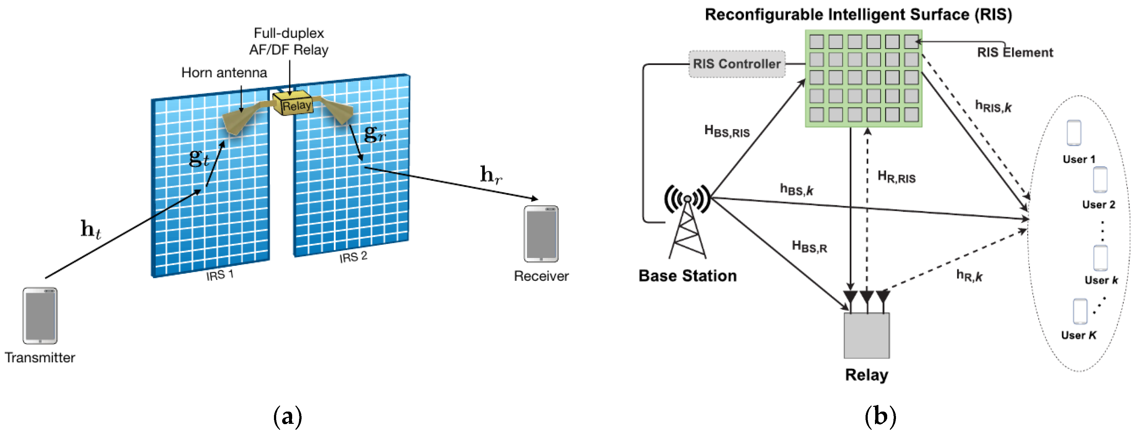
- Nguyen, N.T.; He, J.; Nguyen, V.D.; Wymeersch, H.; Ng, D.W.K.; Schober, R.; Chatzinotas, S.; Juntti, M. Hybrid relay-reflecting intelligent surface-aided wireless communications: Opportunities, challenges, and future perspectives. arXiv 2021, arXiv:2104.02039. [Google Scholar]
- Nguyen, N.T.; Vu, Q.D.; Lee, K.; Juntti, M. Spectral efficiency optimization for hybrid relay-reflecting intelligent surface. In Proceedings of the IEEE International Conference on Communications Workshops (ICC Workshops), Montreal, QC, Canada, 14–23 June 2021. [Google Scholar]
- Ngo, K.H.; Nguyen, N.T.; Dinh, T.Q.; Hoang, T.M.; Juntti, M. Low-latency and secure computation offloading assisted by hybrid relay-reflecting intelligent surface. In Proceedings of the IEEE International Conference on Advanced Technologies for Communications (ATC), Ho Chi Minh City, Vietnam, 14–16 October 2021. [Google Scholar]
- Ahmed, S.; Ahmed, E.K.; Mohamed, Y.S. Adding active elements to reconfigurable intelligent surfaces to enhance energy harvesting for IoT devices. In Proceedings of the IEEE Military ommunications Conference (ATC), San Diego, CA, USA, 29 November–2 December 2021. [Google Scholar]
- Yigit, Z.; Basar, E.; Wen, M.; Altunbas, I. Hybrid reflection modulation. IEEE Trans. Wirel. Commun. 2022, 22, 4106–4116. [Google Scholar] [CrossRef]
- Nguyen, N.T.; Nguyen, V.D.; Wu, Q.; Tölli, A.; Chatzinotas, S.; Juntti, M. Hybrid active-passive reconfigurable intelligent surface-assisted multi-user MISO systems. In Proceedings of the 2022 IEEE 23rd International Workshop on Signal Processing Advances in Wireless Communication (SPAWC), Oulu, Finland, 4–6 July 2022. [Google Scholar]
- Best, S.R. Realized noise figure of the general receiving antenna. IEEE Antennas Wirel. Propag. Lett. 2013, 12, 702–705. [Google Scholar] [CrossRef]
- Kimionis, J.; Georgiadis, A.; Collado, A.; Tentzeris, M.M. Enhancement of RF tag backscatter efficiency with low-power reflection amplifiers. IEEE Trans. Microw. Theory Tech. 2014, 62, 3562–3571. [Google Scholar] [CrossRef]
- Zhang, Z.; Dai, L. Reconfigurable intelligent surfaces for 6G: Nine fundamental issues and one critical problem. Tsinghua Sci. Technol. 2023, 28, 929–939. [Google Scholar] [CrossRef]
- Yang, H.; Yang, F.; Cao, X.; Xu, S.; Gao, J.; Chen, X.; Li, M.; Li, T. A 1600-element dual-frequency electronically reconfigurable reflectarray at X/Ku-Band. IEEE Trans. Antennas Propag. 2017, 65, 3024–3032. [Google Scholar] [CrossRef]
- Wang, J.; Tang, W.; Liang, J.C.; Zhang, L.; Dai, J.Y.; Li, X.; Jin, S.; Cheng, Q.; Cui, T.J. Reconfigurable intelligent surface: Power consumption modeling and practical measurement validation. arXiv 2022, arXiv:2211.00323. [Google Scholar]
- Zappone, A.; Di Renzo, M.; Shams, F.; Qian, X.; Debbah, M. Overhead-aware design of reconfigurable intelligent surfaces in smart radio environments. IEEE Trans. Wirel. Commun. 2020, 20, 126–141. [Google Scholar] [CrossRef]
- Wang, J.; Tang, W.; Jin, S.; Li, X.; Matthaiou, M. Static power consumption modeling and measurement of reconfigurable intelligent surfaces. arXiv 2023, arXiv:2303.00299. [Google Scholar]
- Liang, J.C.; Cheng, Q.; Gao, Y.; Xiao, C.; Gao, S.; Zhang, L.; Jin, S.; Cui, T.J. An Angle-Insensitive 3-Bit Reconfigurable Intelligent Surface. IEEE Trans. Antennas Propag. 2022, 70, 8798–8808. [Google Scholar] [CrossRef]
- Gu, Q.; Wu, D.; Su, X.; Wang, H.; Cui, J.; Yuan, Y. System-level simulation of reconfigurable intelligent surface assisted wireless communications system. arXiv 2022, arXiv:2206.14777. [Google Scholar]
- Sihlbom, B.; Poulakis, M.I.; Di Renzo, M. Reconfigurable intelligent surfaces: Performance assessment through a system-level simulator. IEEE Wirel. Commun. 2023, 30, 98–106. [Google Scholar] [CrossRef]
- Hao, L.; Fastenbauer, A.; Schwarz, S.; Rupp, M. Towards system level simulation of reconfigurable intelligent surfaces. In Proceedings of the 2022 International Symposium ELMAR, Zadar, Croatia, 12–14 September 2022. [Google Scholar]
- Rafique, A.; Hassan, N.U.; Naqvi, I.H.; Mehmood, M.Q.; Zubair, M. Benchmarking framework for reconfigurable intelligent surfaces. In Proceedings of the 2021 IEEE Global Communications Conference (GLOBECOM), Madrid, Spain, 7–11 December 2021. [Google Scholar]
- Swindlehurst, A.L.; Zhou, G.; Liu, R.; Pan, C.; Li, M. Channel estimation with reconfigurable intelligent surfaces—A general framework. Proc. IEEE 2022, 110, 1312–1338. [Google Scholar] [CrossRef]
- Di Renzo, M.; Danufane, F.H.; Tretyakov, S. Communication models for reconfigurable intelligent surfaces: From surface electromagnetics to wireless networks optimization. Proc. IEEE 2022, 110, 1164–1209. [Google Scholar] [CrossRef]
- Press Releases: NTT and NTT DOCOMO Trial First Use of User-Tracking Metasurface Reflector for Extreme Mobile Coverage in Current 5G and Coming 6G Era|News & Notices|NTT DOCOMO. Available online: https://www.docomo.ne.jp/english/info/media_center/pr/2021/1112_00.html (accessed on 8 October 2023).
- Sang, J.; Yuan, Y.; Tang, W.; Li, Y.; Li, X.; Jin, S.; Cheng, Q.; Cui, T.J. Coverage enhancement by deploying RIS in 5G commercial mobile networks: Field trials. IEEE Wirel. Commun. 2023, in press. [Google Scholar] [CrossRef]
- Liu, R.; Dou, J.; Li, P.; Wu, J.; Cui, Y. Simulation and field trial results of reconfigurable intelligent surfaces in 5G networks. IEEE Access 2022, 10, 122786–122795. [Google Scholar] [CrossRef]
- Rains, J.; Tukmanov, A.; Cui, T.J.; Zhang, L.; Abbasi, Q.H.; Imran, M.A. High-Resolution Programmable Scattering for Wireless Coverage Enhancement: An Indoor Field Trial Campaign. IEEE Trans. Antennas Propag. 2023, 71, 518–530. [Google Scholar] [CrossRef]
- Trichopoulos, G.C.; Theofanopoulos, P.; Kashyap, B.; Shekhawat, A.; Modi, A.; Osman, T.; Kumar, S.; Sengar, A.; Chang, A.; Alkhateeb, A. Design and evaluation of reconfigurable intelligent surfaces in real-world environment. IEEE Open J. Commun. Soc. 2022, 3, 462–474. [Google Scholar] [CrossRef]
- Fei, D.; Chen, C.; Zheng, P.; You, M.; Ding, J.; Wang, W.; Zhan, J.; Ai, B.; Jin, S.; Cui, T.J. Research and experimental verification of reconfigurable intelligent surface in indoor coverage enhancement. J. Electron. Inf. Technol. 2022, 44, 2374–2381. [Google Scholar]


| Year | Ref. | Structure | Technologies | Function |
|---|---|---|---|---|
| 2012 | [12] | Intelligent wall | PIN diode, active FSS | Perfect transmission/reflection surface |
| 2014 | [13] | Spatial microwave modulator | Binary phase control metasurface | Microwave field forming |
| 2014 | [11] | Coding metamaterial | Binary phase control metasurface | Reconfigurable scattering pattern |
| 2016 | [14] | Programmable metamaterial | PIN diode, metasurface | Reconfigurable phase, polarization, scattering |
| 2016 | [15] | Reconfigurable reflectarray | Varactor, reflectarray | Adaptive reflection phase |
| 2018 | [4] | Large intelligent surface | Radiation/sensing array, electromagnetic active material | Massive MIMO substitute |
| 2018 | [3] | Software controlled hypersurface | IoT gateway, metasurface | Radio absorption, polarization, beam steering |
| Operation Mode | Characteristics and Functions |
|---|---|
| Reflection |
|
| Refraction |
|
| Absorption |
|
| Backscattering |
|
| Transmitting |
|
| Receiving |
|
| Scenarios | BS–UE Channel Model | BS–RIS Channel Model | RIS–UE Channel Model | RIS–RIS Channel Model |
|---|---|---|---|---|
| Urban deployment: avoiding indoor UE’s penetration loss | Uma/Umi | Uma/Umi | InH/InF | Uma/Umi/InH/InF |
| Urban deployment: UE-controlled RIS | Uma/Umi | Uma/Umi | LoS | N/A |
| Urban deployment: RIS close to BS | Uma/Umi | LoS | Uma/Umi | Umi |
| Urban deployment: coverage extension | Uma/Umi | Uma/Umi | Uma/Umi | Uma/Umi |
| Indoor scenario | InH/InF | InH/InF/LoS | InH/InF/LoS | InH/InF |
| Type | Technology | Stability | Integration | D/A Control | Cost | Loss (M/T) | Bias Power Consumption | Linearity | Switching Time |
|---|---|---|---|---|---|---|---|---|---|
| Circuit | PIN diode | + | − | D | + | −/− | − | o | + |
| Varactor | + | − | D | + | −/− | + | − | + | |
| MEMS | o | + | D | + | +/o | + | + | o | |
| Material | Ferroelectric thin film | o | + | A | o | −/− | + | o | + |
| LC | o | o | A | o | −/+ | o | o | − | |
| Graphene | − | + | A | o | −/+ | + | − | + | |
| Photoconductive | o | − | A | o | −/− | − | − | + | |
| Mechanical | Fluidic | o | − | A | o | o/+ | + | o | − |
| Micromotors | − | − | A | − | + | o | + | − |
| Parameters | RIS | Relay |
|---|---|---|
| Definition | The reflecting surface which scatters incoming EM waves with controllable delay/phase and polarization is known as an RIS. | The device which decodes incoming EM signal, amplifies and retransmit it back is known as a relay. |
| Operating mechanism | Passive/active reflection | Active reception and transmission |
| Duplex | Full | Half/full |
| Number of transmit RF Chains required | Zero | N |
| ADC/DAC and amplifier | Not required | Required |
| Energy consumption | Low | High |
| Spectral efficiency formula | 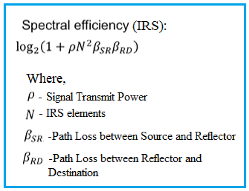 | 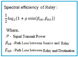 |
| PIN Diode [148] | Varactor Diode [149] | RF Switch [99] | |
|---|---|---|---|
| Operating frequency | 3.5 GHz | 3.2 GHz | 5.3 GHz |
| RIS size | 16 × 16 (8 × 8 sub) | 8 × 16 | 8 × 8 |
| Control | FPGA + 8-bit shift register | DAC(DAC3484) + OP Amp (AD8021) | FPGA XC3S400AN |
| Pc | 4.8 W | 4.8 W | 4.8 W |
| Pd | 0.066 mW Vcc = 3.3 V, Icc = 20 μA | 430 mW (250 mW + 180 mW) Vcc = ±12 V, Icc = 7.5 mA | 240 mW Vcc = 12 V, Icc = 20 mA |
| Ptd | 2.112 mW | 1720 mW | 240 mW |
| Parameters | Nc = 256, Ng = 1, Ns = 8, Ndc = 32 | Nc = 256, Ng = 32, Ns = 1, Ndc = 4 | Nc = 64, Ng = 1, Ns = 75, Ndc = 1 |
| Scenario #1 | Scenario #2 | Scenario #3 | Scenario #4 | Scenario #5 | |
|---|---|---|---|---|---|
| Indoor | Outdoor | Outdoor/Indoor | Outdoor/Indoor | Outdoor/Indoor | |
| Operation frequency | 26 GHz | 26 GHz | 2.6 GHz (60 MHz) | 4.9 GHz (100 MHz) | 26 GHz (100 MHz) |
| RIS size | 64 × 64 | 32 × 32 | 20 × 20 (1 m × 1 m) | 32 × 32 (1 m × 1 m) | 64 × 64 |
| BS–RIS | 20 m | 120 m | 206 m | 145 m | 45 m |
| RIS–UE | 10 m | 20 m | 7 m | 45 m | 106 m |
| RSRP | 1-bit single polarization 30 dB 4-bit double polarization | 1-bit single polarization 30 dB | 1.5-bit single polarization 15 dB | 4-bit dual polarization 21 dB | 1-bit dual polarization 12 dB |
| Data rate | DL: 275% UL: 200% | DL:442% UL: 442% |
| Ref. | Phase Resolution | Tuning Mechanism | Size No. of Elements | Frequency | Bandwidth | Scenarios | Effects on Channel Response |
|---|---|---|---|---|---|---|---|
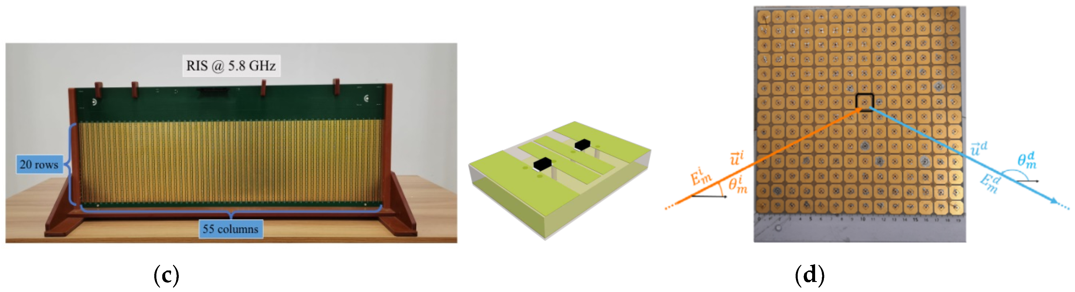
| [79] | 1-bit | Varactor | 0.80 m × 0.31 m (15.5λ × 6λ) 1100 elements (55 × 20) | 5.8 GHz | 500 MHz | Indoor NLOS. Outdoor rooftops at 50 and 500 m. | 27 dB@50 m. 14 dB@500 m. 26 dB@indoor via a thick concrete wall. |
| [160] | 1-bit | PIN diodes | 0.41 m × 0.26 m (7.9λ × 5λ) 160 elements (16 × 10) | 5.8 GHz | 150 MHz | Outdoor NLOS via large occlusion. | 6 dB SNR improvement. |
| [77] | 1-bit | RF switches | 2.45 m × 2.45 m (19.6λ × 19.6λ) 3200 elements (64 × 50) | 2.4 GHz | 38 MHz | Indoor office environment with mixed LOS/NLOS. | Max 9.8 dB Doubling of channel capacity. |
| [161] | 1-bit | PIN diodes | 512 elements (16 × 32) | 2.64 GHz | 160 MHz | Indoor NLOS at a corridor junction. | 10 dB/10 Mbps. |
| [68] | Continuous | Varactor | 1.14 m × 1.16 m (13.3λ × 13.5λ) 2430 elements (30 × 81) | 3.5 GHz | - | Indoor NLOS. Room to room wireless link. | 15 dB. |
| [159] | 3-bit | PIN diodes | 1.02 m × 0.72 m (12.8λ × 9λ) 2304 elements (48 × 48) | 3.75 GHz | 1.5 GHz | Indoor mixed LOS/NLOS. Corridor junctions and multiple floors. | 16 dB. Up to 40 dB in deep fading. Multi-floor 20 dB. |
Disclaimer/Publisher’s Note: The statements, opinions and data contained in all publications are solely those of the individual author(s) and contributor(s) and not of MDPI and/or the editor(s). MDPI and/or the editor(s) disclaim responsibility for any injury to people or property resulting from any ideas, methods, instructions or products referred to in the content. |
© 2023 by the author. Licensee MDPI, Basel, Switzerland. This article is an open access article distributed under the terms and conditions of the Creative Commons Attribution (CC BY) license (https://creativecommons.org/licenses/by/4.0/).
Share and Cite
Hong, I.-P. Reviews Based on the Reconfigurable Intelligent Surface Technical Issues. Electronics 2023, 12, 4489. https://doi.org/10.3390/electronics12214489
Hong I-P. Reviews Based on the Reconfigurable Intelligent Surface Technical Issues. Electronics. 2023; 12(21):4489. https://doi.org/10.3390/electronics12214489
Chicago/Turabian StyleHong, Ic-Pyo. 2023. "Reviews Based on the Reconfigurable Intelligent Surface Technical Issues" Electronics 12, no. 21: 4489. https://doi.org/10.3390/electronics12214489
APA StyleHong, I.-P. (2023). Reviews Based on the Reconfigurable Intelligent Surface Technical Issues. Electronics, 12(21), 4489. https://doi.org/10.3390/electronics12214489