Abstract
The breakdown characteristics are very important for GaN high-electron-mobility transistors (HEMTs), which affect the application voltage, power density, efficiency, etc. In order to further enhance the breakdown voltage of the device, it is necessary to carry out research on the breakdown mechanisms of the device. This article summarizes several breakdown mechanisms of GaN devices, including electric field concentration, buffer leakage current, gate leakage current, and vertical breakdown. In order to suppress the breakdown mechanisms, techniques such as the use of a field plate, reduced surface field (RESURF), back barrier, gate dielectric, substrate removal, and addition of AlGaN channels can be developed. With the continuous development of various technologies, the breakdown characteristics of GaN devices can be fully explored, laying the foundation for improving the performance of power electronic systems.
1. Introduction
Power electronic systems are of crucial importance for generating and converting energy in a sustainable way. As one of the key components for efficient and energy-saving power electronic systems, power semiconductors must be updated with high-voltage devices featuring outstanding performance in static and dynamic energy loss, current density, operating voltage and temperature, etc. [1,2,3,4]. Although silicon (Si) power devices have been widely used in diverse fields and industries, their application prospects are hindered by the limited bandgap and lower critical breakdown electric field.
As the most representative material of the wide bandgap semiconductors, gallium nitride exhibits overwhelming superiorities in terms of band gap, critical breakdown electric field, electron saturation speed, etc., attracting more attention for various applications. Emerging as the most attractive key device in high-power and high-efficiency power conversion systems, the existing fabricated GaN power transistors are characterized by the advantages of high breakdown voltage, high switching speed, low conduction resistance, and high conversion efficiency, and have become an ideal option for future power switch applications.
With respect to power devices, high breakdown voltage properties can improve their potential for different applications. Gallium nitride high-electron-mobility transistors (HEMTs) have prospered ever since M. Asif Khan et al. demonstrated the first AlGaN/GaN HEMT on a sapphire substrate in 1993 [5]. Later, GaN chips gradually became commercialized in 2010, after which, the research interest in GaN HEMTs primarily focused on the devices’ breakdown voltage, normally off characteristics, and reliability. However, the maximum operating voltage is only 650 V for pGaN HEMTs, and 900 V for cascode structures [6,7,8].
This study mainly summarizes the research progress in high-breakdown-voltage nitride HEMTs in recent years. This paper is organized as follows. Section 2 introduces the factors restricting the breakdown performance of GaN HEMT devices, which involve electric field concentration, buffer leakage current, gate leakage current, and vertical breakdown. Section 3 outlines the related approaches and research progress for solving breakdown problems. Section 4 summarizes the conclusions of this paper, presenting an outlook for the future research and applications of gallium nitride power electronics.
2. Breakdown Mechanisms
2.1. Electric Field Concentration
When a conventional gallium-nitride-based HEMT device is biased in off state (VGS < Vth), the electric field line existing in the depletion region directly underneath the gate is perpendicular to the gate electrode. Meanwhile, the shape of the depletion region at the gate edge will bend, causing more electric field lines at the gate edge, where the electric field value is greater than the electric field directly underneath the gate. In real situations, the electric field distributes unevenly in the channel, and the electric field on the drain side of the gate is more concentrated. For this reason, the peak value of the electric field is far higher than that of the access region, as in the peak electric field ① shown in Figure 1.
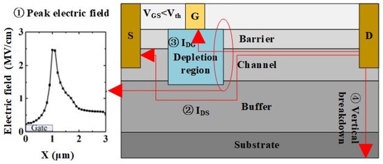
Figure 1.
Possible breakdown mechanisms in GaN-based HEMTs.
2.2. Buffer Leakage Current
Under normal circumstances, gallium-nitride-based materials are epitaxially grown on silicon, sapphire, silicon carbide, or GaN substrates. Due to the lattice mismatch of heterogeneous substrates, defects and impurities can be produced, and the dislocation density of GaN materials is approximately 108 cm−2 [9]. In unintentionally doped GaN films, C, Si, and O are the most common impurities. The concentration of unintentionally introduced carbon is usually in the range of 1015–1018 cm−3, depending on the growth conditions [10,11]. Furthermore, owing to the non-negligible concentration of background electron carriers and those defects and impurities, a potential conductive path may be created, thereby inducing leakage current. When a high voltage is applied to the drain of the device, an excessive leakage current in the buffer layer may result in the pre-breakdown of the device, as the shown path ② in Figure 1. In recent years, researchers have made a lot of optimizations to the buffer layer, such as using a back barrier, AlGaN channel, superlattice, and so on. Other researchers have found that Si doping promotes a reduction in dislocation density [12].
2.3. Gate Leakage Current
Gallium-nitride-based HEMT devices primarily adopt Schottky contacts to form gate electrodes. Due to the limited breakdown capability of Schottky gates and the drastic increase in the leakage current with the increased operating temperature, an excessive gate leakage current from the drain to the gate may result in the pre-breakdown of GaN-based HEMT devices, as shown by path ③ in Figure 1.
2.4. Vertical Breakdown
The quality of substrates and epitaxial materials prevent the vertical breakdown performance of gallium-nitride-based HEMT devices from being improved. Due to the critical breakdown electric field of silicon being 0.3 MV/cm, adopting silicon substrates for fabricating high-breakdown-voltage (>1.5 kV) devices still remains almost unfeasible [4,13,14]. In addition, a large number of dislocations exist in the epitaxial buffer layer, causing a conductive path (④ in Figure 1). Under this circumstance, the leakage current during substrate grounding must not be neglected. Amongst the diverse approaches for improving the breakdown voltage capability of the devices, the most efficient and effective ones are to opt for appropriate substrates and to improve the quality of epitaxial layers.
3. Related Research Progress
3.1. Modulating Electric Field
When a gallium nitride device is in its breakdown voltage state, the electric field lines are concentrated on the edge of the gate near the drain. In response to the above phenomenon, initiating from the purpose of improving the uniformity of the electric field, diverse technologies have been proposed, involving field plate [15,16,17,18,19], reduced surface field (RESURF) [20,21,22], and super heterojunction technologies [23].
When it comes to field plate technology, there are various methods to connect the field plate to the source electrode [15,17], gate electrode [17], or drain electrode [18], etc., to which a floating field plate can also be connected [19]. Adopting a field plate can not only introduce new electric field peaks, but also reduce the curvature and electric field of the depletion zone at the edge of the gate, thereby improving the breakdown voltage when the avalanche effect occurs.
By utilizing the longitudinal depletion effect between epitaxial layers with different doping types, RESURF technology [20,21,22] enhances the average electric field on the surface of GaN-based HEMT devices while reducing the peak electric field, thereby increasing the breakdown voltage of the devices. By adopting state-of-the-art and composite structures, the advantages of GaN materials such as a large bandgap and high-critical-breakdown electric field can be brought into full play.
A double-layer lithography was used to yield a liftoff overhang. Subsequently, the SiNx was removed in the openings using the CF4 reactive ion etching process. The gate metals were e-beam-evaporated on the sample rotating at an angle to the incident metal flux. This resulted in gates with self-aligned slanted field plates. It can be observed from Figure 2 that an approximate positive linear correlation exists between the breakdown voltage and the gate–drain spacing of the device adopting self-aligned slant field plate. At a gate–drain spacing of 20 μm, the breakdown voltage of the device can reach up to 1900 V [24]. Figure 3 presents a structural diagram of the device whose drain is connected to the back side of the substrate. At Lgd = 125 μm, the device’s specific on-resistance and the breakdown voltage are 186 mΩ·cm2 and 8300 V, respectively [18]. The high breakdown voltage is realized by a high-temperature AlN buffer layer, polycrystalline AlN passivation and field plate technologies, and through silicon via TSV. The composite field plate improves the electric field distribution, while via-hole etching reduces the heat generated by the device. The highest breakdown voltage of GaN devices is 10,400 V [25], but its off-state leakage current at 3000 V is close to 0.1 mA/mm. In this case, the loss of GaN HEMTs becomes non-negligible. Although such a high off-state leakage current reduces the application prospect of the device, it provides great reference significance for subsequent studies.

Figure 2.
Device with slant field plate [24]: (a) schematic diagram of its structure; (b) breakdown voltage varying with Lgd.

Figure 3.
Device with AlN passivation and via-holes through the substrate [18,25]: (a) structural diagram and (b) breakdown characteristics.
The electrode on the back side of the device can adjust the electric field distribution at the AlGaN/GaN surface by inducing negative charges to form a more uniformly distributed horizontal electric field at the channel, by which the breakdown voltage of the device is therefore greatly improved. As shown in Figure 4, the breakdown voltage of a conventional AlGaN/GaN HEMT device fabricated using RESURF technology is 1118 V. After adding a back side electrode, the breakdown voltage of the device is increased by more than 50% (up to 1701 V) [20], which imposes almost no effect on its specific on-resistance (Ron). Figure 5 shows the HEMT device featured with multiple channels (MC2-HEMT), which is realized by integrating a low-voltage normally off single-channel HEMT with a high-voltage normally on multi-channel HEMT. The device adopts a grooved gate and RESURF technologies to realize an enhanced structure and high breakdown voltage, respectively. Specifically, at a gate–drain spacing of 103 μm, the breakdown voltage of this device can reach up to 10 kV. As for the other parameters of the device, its specific on-resistance is 40 mΩcm2, and the Baliga figure of merit (BFOM) reaches up to 2.84 GW/cm2, exhibiting the unique and exclusive material advantages of GaN [21].
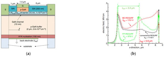
Figure 4.
(a) Structural diagram of RESURF HEMT with back electrode; (b) electric field distribution at the channel when breakdown happens [20].

Figure 5.
(a) Structural diagram of MC2-HEMT and its (b) breakdown characteristics varying with Lgd [21].
Instead of introducing complicated fabrication processes, drift region width modulation (DWM) technology can be used to redistribute the charges between the gate and drain, by which the realized adaptive-width drift HEMT (AWD-HEMT) device is capable of realizing a more uniformly distributed electric field on the interface/surface of AlGaN/GaN device.
Figure 6a provides a structural diagram of the AWD-HEMT in comparison to that of a conventional HEMT, in which the BFOM of the device is improved by 65.3% [26]. As shown in Figure 6c, the breakdown voltage of the device improves from 49 V to 955 V by adopting fluoride ion implantation technology. First, fluoride ions were implanted into the thick passivation layer as a terminal, and then the implantation area of the fluoride ions was gradually reduced. As shown in Figure 6d, the above two procedures together are more conducive to forming a uniformly distributed electric field; throughout the whole process, the passivation layer stays far away from two-dimensional electron gas, thereby imposing little effect on the saturation current. Figure 7a illustrates that the effect similar to that achieved by adopting RESURF can be realized by implanting fluoride ions into the buffer layer of the device to adjust the distribution of the internal electric field within the device.

Figure 6.
Structural diagram of (a) AWM-HEMT and its (b) local enlargement [26]; (c) the device fabricated by fluoride ion implantation and its (d) electric field distribution [27].

Figure 7.
(a) Electric field distribution of the device fabricated by fluoride ion implantation [22]; (b) breakdown characteristics of MISHEMT with different passivation layers [28].
Raising the back barrier helps to reduce the off-state leakage current, thereby increasing the breakdown voltage of the device from 230 V to 750 V [22]. When using different passivation layers to create a metal insulator semiconductor high-electron-mobility transistor (MISHEMT), it is found that the passivation layer with low vacuum permittivity can effectively disperse the electric field, thereby increasing the breakdown voltage of the device. As shown in Figure 7b, by using the above technology, the breakdown voltage of the device with a low-k passivation layer can be improved by 600 V, which is a 250% improvement compared with the original value [28].
3.2. Reducing Buffer Leakage Current
In response to the problem of high defect concentration in the material fabrication, the use of C-doping or Fe-doping to compensate for the buffer layer helps to suppress the background carriers generated by excessive defects, thereby improving the insulation performance of GaN materials. The notion of a “back barrier” refers to adding an AlGaN barrier layer underneath the channel area of the device to increase the barrier height between the channel and the buffer layer, which prevents two-dimensional electron gas from penetrating into the buffer layer due to the high drain voltage. When the channel of the device is in the off state, the buffer layer leakage current caused by high voltage is suppressed, thereby improving the breakdown performance of the device.
Specifically, by using C-doping to compensate the buffer layer, the breakdown voltage of the HEMT device can approximate up to 1000 V when the doping concentration is 4 × 1019 cm−3 [29]. As shown in Figure 8a, the carrier confinement is better because the back barrier structure exhibits a higher barrier height underneath the channel of the two-dimensional electron gas, thereby greatly reducing the drain leakage current while improving the breakdown voltage of the device. At a gate–drain spacing of 1 μm, the breakdown voltage of double-heterojunction HEMT devices (100 V) is twice that of conventional ones (50 V) [30], which is shown in Figure 8b. A1, A2, and A3 are single-heterojunction devices, and B1, B2, and B3 are double-heterojunction devices. By combining the back barrier and Si-doping techniques, HEMT devices can be fabricated with a high breakdown voltage exceeding 1000 V [31].
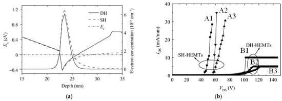
Figure 8.
Double-heterojunction and single-heterojunction HEMTs (a) energy band diagram and electron concentration distribution, and (b) off-state breakdown characteristics [30].
As shown in Figure 9a, by monolithically integrating gallium-nitride-based HEMT with silicon-carbide-based PN-junction diodes, the device achieved a breakdown voltage of 1.27 kV [32]. The above achievement indicates that the diode is capable of reducing gate and buffer leakage current, thereby endowing the device with excellent avalanche breakdown characteristics. For the AlGaN/GaN HEMT fabricated on a free-standing GaN substrate, when Lgd < 80 μm, the off-state breakdown voltage is positively linearly correlated with the gate–drain spacing, and then it saturates at 4000 V when Lgd = 80 μm [33]. As shown in Figure 9b, the small lattice mismatch between the GaN substrate and epitaxial GaN material significantly reduces the dislocation density through which the high-voltage characteristics of the GaN substrate are obtained.
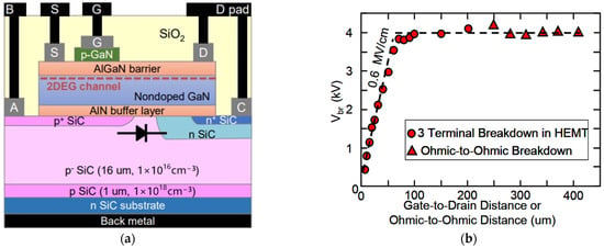
Figure 9.
(a) Monolithic integration of HEMT device [32]; (b) variation in breakdown voltage with gate–drain or ohmic–ohmic distance for free-standing GaN substrate [33].
3.3. Reducing Gate Leakage Current
The gate electrodes of HEMT devices are mainly Schottky contacts. Unfortunately, the leakage current of the Schottky gate is large and increases obviously as the operating temperature of the device increases, which can increase the gate leakage current and reduce the gate–drain breakdown voltage. To address this phenomenon, using different metal or metal insulator semiconductor (MIS) structures to fabricate the gate significantly helps reduce the gate leakage current at the off-state, thereby improving the breakdown voltage of the device. In order to achieve better breakdown performance, an appropriate material for fabricating the gate dielectric must be chosen carefully.
An HEMT device using tungsten as the gate metal is capable of ensuring low gate leakage current while exhibiting high threshold voltage. The device is fabricated using a buffer layer with a thickness of 5.2 μm, and the breakdown voltage of the layer and the device itself exceeds 1600 V, of which the specific on-resistance of the device is 2.9 mΩcm2. The FOM of the device can reach up to 921 MV2/Ωcm2 [1].
As shown in Figure 10a, by adopting the manufacturing process involving the gold-free technique and atomic layer deposition (ALD) fabricating Al2O3 as the gate dielectric, the fabricated MOS-HEMT exhibits a breakdown voltage of 800 V at a gate–drain spacing of 5 μm. Its leakage current is less than 3.8 × 10⁻⁷ A/mm when the drain voltage is less than 650 V [34]. Within the range of several hundred volts of the applied voltage, the HEMT device, using the gold-free technique, exhibits overwhelming competitive advantages in terms of cost. It can be observed from Figure 10b that the AlGaN back barrier structure and the SiO2 gate dielectric are utilized to reduce the leakage currents. The gate leakage current of the device stays within the range of 10−10 A/mm, which is six orders of magnitude lower than that of the HEMT device adopting the Schottky barrier. By adopting the above techniques, an InAlN/GaN MOS-HEMT device was successfully devised, characterized by a breakdown voltage of 3000 V and a specific on-resistance of 4.25 mΩcm2; its power FOM achieves up to 2.1 × 10⁹ V2Ω−1cm−2 [35].
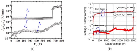
Figure 10.
Breakdown characteristics of MOS-HEMTs with (a) Al2O3 as the gate dielectric [34] or (b) with AlGaN back barrier [35].
As shown in Figure 11, an HEMT device with gate insulators fabricated using fluoride ion implantation was combined with 17 nm SiNx thin film deposited using plasma-enhanced chemical vapor deposition (PECVD), which achieved a threshold voltage of +3.6 V, a specific on-resistance of 2.1 mΩcm2, and a breakdown voltage of 604 V [13]. In addition to the above, adopting AlN/SiNx dual-layer passivation can effectively suppress the current collapse effect, thereby improving the dynamic characteristics of the device. Figure 12 shows an HEMT device featured with a 10 nm SiN insulation layer deposited by PECVD and with an AlGaN channel. Specifically, the adoption of an MIS structure reduces the forward and reverse leakage currents by one order and four orders of magnitude, respectively. The low gate leakage current provides the device with excellent breakdown characteristics, which not only achieves a breakdown field strength of 1.8 MV/cm, but also a relatively small increase in its specific on-resistance at high temperatures [36].

Figure 11.
(a) Device schematic structure and (b) breakdown characteristics of MIS-HEMTs with AlN/SiNx passivation [13].

Figure 12.
(a) Device schematic structure, (b) I-V characteristics of the gate–drain Schottky diode, and (c) breakdown characteristics of AlGaN channel HEMTs [36].
As shown in Figure 13, the SiNx thin film deposited using low-pressure chemical vapor deposition (LPCVD) at 780 °C is used to replace PECVD-SiNx thin film as the gate dielectric layer of the device. Using this technique, the forward and reverse gate leakage currents of the layer are significantly reduced, which gives the device a higher forward gate breakdown voltage (24 V at room temperature) [14].

Figure 13.
(a) Device schematic structure, (b) breakdown characteristics, and (c) IG–VGS characteristics of MIS-HEMTs using LPCVD-SiNx as gate dielectric [14].
Figure 14 demonstrates an MIS-HEMT device fabricated using a ferroelectric engineered charge trap gate in which a La-doped Hf0.5Zr0.5O2 (HZLO) with a seed layer (SL) functions as the gate dielectric. Since the technique is adopted in HZO, the effect of soft breakdown is therefore mitigated, thereby reducing the leakage current and the off-state breakdown voltage of the device can reach up to 917 V at VGS = 0 [37].
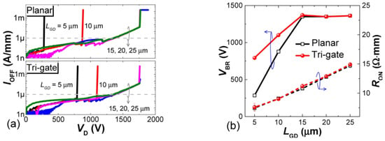
Figure 14.
(a) Breakdown characteristics of the planar and tri-gate. (b) Extracted LGD-dependent RON and VBR of the MOSHEMTs [38].
Owing to the increase in effective LGD and the implementation of an integrated field plate (FP), adopting the tri-gate technique can greatly reduce the off-state leakage current of the HEMT device (lower than 1 μA/mm), thereby improving its ratio of on/off current and breakdown voltage. In particular, the VBR of tri-gate MOS-HEMTs are 792 V, 1100 V, and 1755 V at a gate–drain spacing of 5 μm, 10 μm, and 15 μm, respectively, and its power FOM can achieve 1.25 GW/cm2 [38]. The aforementioned achievements have formulated the unique superiority of GaN transistor in power conversion circuit.
3.4. Improving Vertical Breakdown Voltage
The vertical breakdown voltage of the HEMT device is limited by its substrate material. Figure 15 illustrates an HEMT device with its original Si substrate being removed and its AlGaN/GaN structure being transferred onto insulating material. By applying this technique to a standard AlGaN/GaN HEMT device grown on Si substrate, the specific on-resistance and the breakdown voltage of the device achieved 5.3 mΩcm2, and higher than 1500 V on the 2 μm epitaxial layer. For an HEMT device, the performance improvement differs when using diverse insulating materials; the use of AlN helps improve the thermal conductivity of the device with a Si-based substrate [39].

Figure 15.
(a) Process flow of the substrate transfer technology and (b) breakdown voltage as a function of LSD of devices [39].
Figure 16 demonstrates an HEMT device that is fabricated by adopting a thick in situ gate dielectric layer and removing the local Si substrate. The device is combined with a 15 μm AlN dielectric layer and then deposited with Cu. Using the above manufacturing technique, the most advanced high-voltage GaN-on-Si power transistor was fabricated. In particular, the transistor is capable of realizing a breakdown voltage of up to 3 kV and a specific on-resistance of 10 mΩcm2, and its vertical breakdown voltage is also improved from 850 V to 2.6 kV. This suggests that the conductive effect of the substrate can be effectively alleviated by removing the substrate and using a dielectric layer [40].
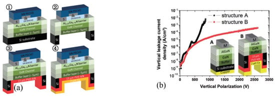
Figure 16.
(a) AlGaN/GaN MISHEMT using local substrate removal technology and (b) its vertical characteristics [40].
It can be observed from Figure 17 that under the circumstances of grounded substrate and LGD = 23 μm, the p-GaN HEMT device achieved a high breakdown voltage of 1740 V, and that the vertical breakdown voltage of p-GaN-on-SiC device exceeded 3 kV, which can be attributed to the semi-insulating and high critical electric field properties of the SiC substrate [41]. Due to the excellent thermal conductivity of the SiC substrate, the above device exhibits minimal degradation at high temperatures, and the drift of its threshold voltage is negligible. These results reveal the great application potential of the p-GaN-gate HEMT on a SiC substrate at higher temperature and voltage.
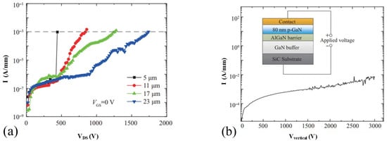
Figure 17.
(a) Breakdown characteristic of p-GaN-on-SiC HEMT and (b) its vertical breakdown characteristic [41].
3.5. Improving the Withstand Voltage of Material
For silicon material, the bandgap and critical breakdown field strength are 1.12 eV and 0.3 MV/cm, respectively. Comparatively, the bandgap and critical breakdown field strength of gallium nitride material are 3 times (3.45 eV) and 11 times (3.3 MV/cm) that of Si material, respectively. As for aluminum nitride, these figures are 1.7 times (6.02 eV) and 3.6 times (12 MV/cm) that of GaN material. This suggests that the intrinsic advantages of the wide bandgap material can improve the performance of HEMT devices. Despite the fact that using AlGaN channels to replace GaN channels can improve the breakdown voltage of devices by increasing the critical breakdown field strength of the channel layer, the electron mobility in the AlGaN channel will be noticeably reduced, which should not be negligible.
Figure 18a illustrates that the breakdown voltages of 462 V and 1650 V were achieved by the AlGaN HEMT device using an AlGaN channel at a gate–drain spacing of 3 μm and 10 μm, respectively, exhibiting the advantages of the AlGaN channel in high-voltage and high-power applications [42]. As shown in Figure 18b, by combining a Schottky drain with an AlGaN channel, both the forward and reverse blocking voltage of the realized HEMT device exceeded 3000 V for the first time. For the Schottky drain HEMT with LGD = 22 μm, the specific on-resistance RON achieved 12.9 mΩcm2, and the forward and reverse power figure of merit reached up to 447 MW/cm2 and 326 MW/cm2, respectively. This result is the highest value ever reported in a reverse blocking GaN HEMT device [43]. As for the GaN-on-Si HEMT devices characterized by an AlGaN channel that contains different Al compositions, the GaN-on-Si HEMTs exhibit a high breakdown electric field of 2.5 MV/cm. To conclude, the adoption of an AlGaN channel not only elevates the breakdown voltage of three-terminal transistors, but also provides benefits such as excellent thermal stability due to the AlGaN in the on-silicon HEMT device [44].

Figure 18.
(a) LGD dependence of the breakdown voltage for AlGaN channel HEMTs [42]. (b) Forward and reverse blocking characteristics for AlGaN channel HEMTs [43].
Figure 19 shows an HEMT device manufactured with an AlN/GaN superlattice channel layer on a silicon substrate. The vertical breakdown voltage of the material is 1020 V, and the breakdown voltages of the device are 670 V and 1700 V at a gate–drain spacing of 8 μm and 22 μm, respectively. The AlN/GaN superlattice channel layer exhibits its unique advantage on electron mobility, laying the theoretical foundation for the preparation of GaN-on-Si HEMT devices with AlGaN channel layers [45].
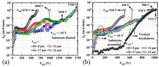
Figure 19.
Breakdown characteristics of the AlN/GaN superlattice channel HEMTs: (a) substrate-floated and (b) grounded [45].
4. Conclusions
This paper summarizes the research progress of breakdown enhancement for GaN-based HEMTs. The future of high-voltage GaN devices is mainly focused on electric field modulation, reducing leakage current, improving vertical breakdown characteristics, etc.
It is still necessary to continue to study the growth technology of high-quality epitaxial materials, new device structures, new terminal technologies, and improved packaging technologies. The field plate structure can induce more electric field peaks, thereby alleviating the peak electric field at the gate edge and improving breakdown. The RESURF structure can make the electric field more uniform through the pn junction. The back barrier structure or doping process can reduce the leakage of the buffer layer. Adding a gate dielectric can reduce gate leakage. The use of SiC or sapphire substrate can avoid the vertical breakdown of Si substrates. The AlGaN channel adopts materials with a higher critical breakdown electric field. By using these methods, GaN devices can achieve better breakdown characteristics. With the development of technology, the breakdown characteristics of GaN devices will be fully explored, resulting in the higher performance of related power supplies.
Table 1 summarizes the typical voltage enhancement methods for the GaN HEMT devices mentioned in this paper and compares their breakdown voltage, average electric field, and figure of merit. In general, GaN-based HEMTs adopt composite field plates, high-quality passivation, substrate selection, and other technologies to modulate the electric field distribution and reduce leakage current. The highest value of the breakdown voltage of the device has already reached 10 kV, and the FOM has reached 2 GW/cm2, but the average electric field is mostly at the level of 1–2 MV/cm.

Table 1.
High-voltage technology summary.
GaN-based HEMTs have attracted much attention in power supply, electric vehicle, data center, aerospace, and other fields due to their large bandgap, high critical breakdown field strength, high mobility of 2DEG, and high saturation speed. GaN-based power electronic devices have broken through the theoretical limit of Si materials and gradually approached the theoretical limit of SiC materials, but are far from reaching the theoretical limit of GaN materials. However, due to the limitations of the breakdown voltage and on-state resistance of the device, GaN products are currently concentrated below 650 V. It is still necessary to continue to study the growth technology of high-quality epitaxial materials, novel device structures, device characteristics, and reliability. High-voltage GaN HEMT devices are likely to be realized on sapphire substrates using modulated electric fields and high-quality passivation.
Author Contributions
Conceptualization, P.L.; methodology, X.J.; formal analysis, D.Y.; investigation, X.J. and D.Y.; data curation, Z.T.; writing—original draft preparation, Z.T.; writing—review and editing, Z.T. All authors have read and agreed to the published version of the manuscript.
Funding
This research received no external funding.
Data Availability Statement
Not applicable.
Conflicts of Interest
The authors declare no conflict of interest.
References
- Hwang, I.; Choi, H.; Lee, J.W.; Choi, H.S.; Kim, J.; Ha, J.; Um, C.Y.; Hwang, S.K.; Oh, J.; Kim, J.Y.; et al. 1.6 kV, 2.9 mΩ cm2 normally-off p-GaN HEMT device. In Proceedings of the 2012 24th International Symposium on Power Semiconductor Devices and ICs, Bruges, Belgium, 3–7 June 2012; pp. 41–44. [Google Scholar]
- Zhao, S.; Zhang, J.; Feng, Q.; Du, L.; Zhang, W.; Ji, S.; Song, X.; Wu, F.; Zhang, W.; Bian, Z.; et al. Parameter Shift of Quasi-Vertical GaN-on-Si Schottky Barrier Diodes under On-State Forward-Current (2–4 kA/cm2) Stress. IEEE Trans. Electron Devices 2023, 70, 959–962. [Google Scholar]
- Wu, Y.; Zhang, W.; Zhang, J.; Zhao, S.; Luo, J.; Tan, X.; Mao, W.; Zhang, C.; Zhang, Y.; Cheng, K.; et al. Au-Free Al0.4Ga0.6N/Al0.1Ga0.9N HEMTs on Silicon Substrate with High Reverse Blocking Voltage of 2 kV. IEEE Trans. Electron Devices 2021, 68, 4543–4549. [Google Scholar]
- Wu, Y.; Liu, S.; Zhang, J.; Zhao, S.; Li, X.; Zhang, K.; Ai, Y.; Zhang, W.; Chen, T.; Hao, Y. Novel In-Situ AlN/p-GaN Gate HEMTs with Threshold Voltage of 3.9 V and Maximum Applicable Gate Voltage of 12.1 V. IEEE Trans. Electron Devices 2023, 70, 424–428. [Google Scholar]
- Asif Khan, M.; Bhattarai, A.; Kuznia, J.N.; Olson, D.T. High electron mobility transistor based on a GaN-AlxGa1−xN heterojunction. Appl. Phys. Lett. 1993, 63, 1214–1215. [Google Scholar]
- Wu, Y.; Zhang, J.; Zhao, S.; Wu, Z.; Wang, Z.; Mei, B.; Duan, C.; Zhao, D.; Zhang, W.; Liu, Z.; et al. Investigation of heavy ion irradiation effects on 650-V p-GaN normally-off HEMTs. Sci. China Inf. Sci. 2022, 65, 182404. [Google Scholar]
- Liu, S.; Li, S.; Zhang, C.; Li, N.; Tao, X.; Ge, C.; Qian, L.; Xin, S.; Sun, W. Single Pulse Unclamped-Inductive-Switching Induced Failure and Analysis for 650 V p-GaN HEMT. IEEE Trans. Power Electron. 2020, 35, 11328–11331. [Google Scholar] [CrossRef]
- Wei, Y.; Hossain, M.M.; Sweeting, R.; Mantooth, H.A. Cryogenic Temperature Characterizations of State-of-the-art Cascode 900 V GaN FET. In Proceedings of the 2021 AIAA/IEEE Electric Aircraft Technologies Symposium (EATS), Virtual, 11–13 August 2021; pp. 1–11. [Google Scholar]
- Kyle, E.C.; Kaun, S.W.; Burke, P.G.; Wu, F.; Wu, Y.R.; Speck, J.S. High-electron-mobility GaN grown on free-standing GaN templates by ammonia-based molecular beam epitaxy. J. Appl. Phys. 2014, 115, 193702. [Google Scholar]
- Reshchikov, M.A.; Vorobiov, M.; Andrieiev, O.; Ding, K.; Izyumskaya, N.; Avrutin, V.; Usikov, A.; Helava, H.; Makarov, Y. Determination of the concentration of impurities in GaN from photoluminescence and secondary-ion mass spectrometry. Sci. Rep. 2020, 10, 2223. [Google Scholar]
- Zhang, G.Y.; Tong, Y.Z.; Yang, Z.J.; Jin, S.X.; Li, J.; Gan, Z.Z. Relationship of background carrier concentration and defects in GaN grown by metalorganic vapor phase epitaxy. Appl. Phys. Lett. 1997, 71, 3376–3378. [Google Scholar]
- Zambrano-Serrano, M.A.; Hernández, C.A.; de Melo, O.; Behar, M.; Gallardo-Hernández, S.; Casallas-Moreno, Y.L.; Ponce, A.; Hernandez-Robles, A.; Bahena-Uribe, D.; Yee-Rendón, C.M.; et al. Effects of heavy Si doping on the structural and optical properties of n-GaN/AlN/Si(111) heterostructures. Mater. Res. Express 2022, 9, 065903. [Google Scholar] [CrossRef]
- Tang, Z.; Jiang, Q.; Lu, Y.; Huang, S.; Yang, S.; Tang, X.; Chen, K.J. 600-V Normally off SiNx/AlGaN/GaN MIS-HEMT with Large Gate Swing and Low Current Collapse. IEEE Electron Device Lett. 2013, 34, 1373–1375. [Google Scholar] [CrossRef]
- Hua, M.; Liu, C.; Yang, S.; Liu, S.; Fu, K.; Dong, Z.; Cai, Y.; Zhang, B.; Chen, K.J. GaN-based metal-insulator-semiconductor high-electron-mobility transistors using low-pressure chemical vapor deposition SiNx as gate dielectric. IEEE Electron Device Lett. 2015, 36, 448–450. [Google Scholar] [CrossRef]
- Saito, W.; Takada, Y.; Kuraguchi, M.; Tsuda, K.; Omura, I.; Ogura, T.; Ohashi, H. High Breakdwon Votage AlGaN-GaN Power-HEMT Design and High Current Density Switiching Behavior. IEEE Trans. Electron Devices 2003, 50, 2528–2531. [Google Scholar] [CrossRef]
- Xie, G.; Xu, E.; Lee, J.; Hashemi, N.; Zhang, B.; Fu, F.Y.; Ng, W.T. Breakdown-Voltage-Enhancement Technique for RF-Based Al Ga N/Ga N HEMTs with a Source-Connected Air-Bridge Field Plate. IEEE Electron Device Lett. 2012, 33, 670–672. [Google Scholar] [CrossRef]
- Xing, H.; Dora, Y.; Chini, A.; Heikman, S.; Keller, S.; Mishra, U.K. High Breakdown Voltage Al Ga N–Ga N HEMTs Achieved by Multiple Field Plates. IEEE Electron Device Lett. 2004, 25, 161–163. [Google Scholar] [CrossRef]
- Uemoto, Y.; Shibata, D.; Yanagihara, M.; Ishida, H.; Matsuo, H.; Nagai, S.; Batta, N.; Li, M.; Ueda, T.; Tanaka, T.; et al. 8300V blocking voltage AlGaN/GaN power HFET with thick poly-AlN passivation. In Proceedings of the 2007 IEEE International Electron Devices Meeting, Washington, DC, USA, 10–12 December 2007; pp. 861–864. [Google Scholar]
- Bahat-Treidel, E.; Hilt, O.; Brunner, F.; Sidorov, V.; Würfl, J.; Tränkle, G. AlGaN/Ga N/AlGaN DH-HEMTs Breakdown Voltage Enhancement Using Multiple Grating Field Plates (MGFPs). IEEE Trans. Electron Devices 2010, 57, 1208–1216. [Google Scholar] [CrossRef]
- Zhao, Z.; Zhao, Z.; Luo, Q.; Du, J. High-voltage RESURF AlGaN/GaN high electron mobility transistor with back electrode. Electron. Lett. 2013, 49, 1638–1640. [Google Scholar] [CrossRef]
- Xiao, M.; Ma, Y.; Du, Z.; Pathirana, V.; Cheng, K.; Xie, A.; Beam, E.; Cao, Y.; Udrea, F.; Wang, H.; et al. Multi-channel monolithic-cascode HEMT (MC2-HEMT): A new GaN power switch up to 10 kV. In Proceedings of the IEEE International Electron Devices Meeting (IEDM), San Francisco, CA, USA, 13–15 December 2021; pp. 5.5.1–5.5.4. [Google Scholar]
- Xiong, J.; Yang, C.; Wei, J.; Wu, J.; Zhang, B.; Luo, X. Novel high voltage RESURF AlGaN/GaN HEMT with charged buffer layer. Sci. China 2016, 59, 042410. [Google Scholar] [CrossRef]
- Nakajima, A.; Sumida, Y.; Dhyani, M.H.; Kawai, H.; Narayanan, E.M. Ga N-Based Super Heterojunction Field Effect Transistors Using the Polarization Junction Concept. IEEE Electron Device Lett. 2011, 32, 542–544. [Google Scholar] [CrossRef]
- Dora, Y.; Chakraborty, A.; Mccarthy, L.; Keller, S.; DenBaars, S.P.; Mishra, U.K. High breakdown voltage achieved on AlGaN/GaN HEMTs with integrated slant field plates. IEEE Electron Device Lett. 2006, 27, 713–715. [Google Scholar] [CrossRef]
- Yanagihara, M.; Uemoto, Y.; Ueda, T.; Tanaka, T.; Ueda, D. Recent advances in GaN transistors for future emerging applications. Phys. Status Solidi 2009, 206, 1221–1227. [Google Scholar] [CrossRef]
- Liu, J.; Zhang, J.; Yao, J.; Li, M.; Chen, J.; Zhang, M.; Huang, X.; Huang, C.; Tang, W.; Guo, Y. The Drift Region Width Modulation Technique for Breakdown Performance Enhancement of AlGaN/GaN HEMT. Electron Devices Soc. 2022, 10, 983–988. [Google Scholar] [CrossRef]
- Deng, S.; Luo, X.; Wei, J.; Jia, Y.; Sun, T.; Xi, L.; Jiang, Z.; Yang, K.; Jiang, Q.; Zhang, B. High Breakdown Voltage AlGaN/GaN HEMT with Graded Fluorine Ion Implantation Terminal in Thick Passivation Layer. In Proceedings of the 2021 IEEE Workshop on Wide Bandgap Power Devices and Applications in Asia (WiPDA Asia), Online, 25–27 August 2021; pp. 403–406. [Google Scholar]
- Tsai, Y.L.; Chang, T.C.; Tsao, Y.C.; Tai, M.C.; Tu, H.Y.; Chien, Y.T.; Jin, F.Y.; Zheng, H.X.; Lin, Y.S.; Ciou, F.M.; et al. Improving Breakdown Voltage in AlGaN/GaN Metal-Insulator-Semiconductor HEMTs through Electric-Field Dispersion Layer Material Selection. IEEE Trans. Device Mater. Reliab. 2021, 21, 320–323. [Google Scholar] [CrossRef]
- Bahat-Treidel, E.; Brunner, F.; Hilt, O.; Cho, E.; Wurfl, J.; Trankle, G. AlGaN/GaN/GaN:C Back-Barrier HFETs with Breakdown Voltage of Over 1 kV and Low RON × A. IEEE Trans. Electron Devices 2010, 57, 3050–3058. [Google Scholar] [CrossRef]
- Ma, J.; Zhang, J.; Xue, J.; Lin, Z.; Liu, Z.; Xue, X.; Ma, X.; Hao, Y. Characteristics of AlGaN/GaN/AlGaN double heterojunction HEMTs with an improved breakdown voltage. J. Semicond. 2012, 33, 014002. [Google Scholar] [CrossRef]
- Cho, E.; Brunner, F.; Zhytnytska, R.; Kotara, P.; Würfl, J.; Weyers, M. Enhancement of channel conductivity in AlGaN/GaN heterostructure field effect transistors by AlGaN:Si back barrier. Appl. Phys. Lett. 2011, 99, 103505. [Google Scholar]
- Nakajima, A.; Hirai, H.; Miura, Y.; Harada, S. 1.2 kV GaN/SiC-based Hybrid High Electron Mobility Transistor with Non-destructive Breakdown. In Proceedings of the 2021 IEEE International Electron Devices Meeting (IEDM), San Francisco, CA, USA, 13–15 December 2021; pp. 36.5.1–36.5.4. [Google Scholar]
- Ng, J.H.; Tone, K.; Asubar, J.T.; Tokuda, H.; Kuzuhara, M. High breakdown voltage AlGaN/GaN HEMTs on free-standing GaN substrate. In Proceedings of the 2015 IEEE International Meeting for Future of Electron Devices, Kansai (IMFEDK), Kyoto, Japan, 4–5 June 2015; pp. 54–55. [Google Scholar]
- Liu, X.; Zhan, C.; Chan, K.W.; Liu, W.; Tan, L.S.; Teo, K.L.; Chen, K.J.; Yeo, Y.C. AlGaN/GaN-on-Silicon MOS-HEMTs with breakdown voltage of 800 V and on-state resistance of 3 mΩ cm2 using a CMOS-compatible gold-free process. In Proceedings of the Technical Program of 2012 VLSI Technology, System and Application, Hsinchu, Taiwan, 23–25 April 2012; pp. 1–2. [Google Scholar]
- Lee, H.-S.; Piedra, D.; Sun, M.; Gao, X.; Guo, S.; Palacios, T. 3000-V 4.3-mΩ·cm2 InAlN/GaN MOSHEMTs with AlGaN Back Barrier. IEEE Electron Device Lett. 2012, 33, 982–984. [Google Scholar]
- Li, X.; Zhang, W.; Fu, M.; Zhang, J.; Jiang, H.; Guo, Z.; Zou, Y.; Jiang, R.; Shi, Z.; Hao, Y. AlGaN channel MIS-HEMTs with a very high breakdown electric field and excellent high-temperature performance. IEICE Electron. Express 2015, 12, 20150694. [Google Scholar] [CrossRef][Green Version]
- Wu, J.S.; Liao, P.H.; Chang, S.J.; Yang, T.Y.; Teng, C.Y.; Liang, Y.K.; Panda, D.; Luc, Q.H.; Chang, E.Y. Superior Breakdown, Retention, and TDDB Lifetime for Ferroelectric Engineered Charge Trap Gate E-mode GaN MIS-HEMT. In Proceedings of the 2022 International Electron Devices Meeting (IEDM), San Francisco, CA, USA, 3–7 December 2022; pp. 847–850. [Google Scholar]
- Ma, J.; Matioli, E. High performance tri-gate GaN power MOSHEMTs on silicon substrate. IEEE Electron Device Lett. 2017, 38, 367–370. [Google Scholar] [CrossRef]
- Lu, B.; Palacios, T. High Breakdown (>1500 V) AlGaN/GaN HEMTs by Substrate-Transfer Technology. IEEE Electron Device Lett. 2010, 31, 951–953. [Google Scholar] [CrossRef]
- Dogmus, E.; Zegaoui, M.; Medjdoub, F. GaN-on-silicon high-electron-mobility transistor technology with ultra-low leakage up to 3000 V using local substrate removal and AlN ultra-wide bandgap. Appl. Phys. Express 2018, 11, 034102. [Google Scholar] [CrossRef]
- Zhao, S.; Zhang, J.; Zhang, Y.; Feng, L.; Liu, S.; Song, X.; Yao, Y.; Luo, J.; Liu, Z.; Xu, S.; et al. 1.7 kV normally-off p-GaN gate high-electron-mobility transistors on a semi-insulating SiC substrate. Sci. China Inf. 2023, 66, 122407. [Google Scholar] [CrossRef]
- Nanjo, T.; Takeuchi, M.; Suita, M.; Oishi, T.; Abe, Y.; Tokuda, Y.; Aoyagi, Y. Remarkable breakdown voltage enhancement in AlGaN channel high electron mobility transistors. Appl. Phys. Lett. 2008, 92, 263502. [Google Scholar] [CrossRef]
- Wu, Y.; Zhang, J.; Zhao, S.; Zhang, W.; Zhang, Y.; Duan, X.; Chen, J.; Hao, Y. More than 3000 V reverse blocking Schottky-drain AlGaN-channel HEMTs with >230 MW/cm2 power figure-of-merit. IEEE Electron Device Lett. 2019, 40, 1724–1727. [Google Scholar] [CrossRef]
- Mehta, J.; Abid, I.; Bassaler, J.; Pernot, J.; Ferrandis, P.; Rennesson, S.; Ngo, T.H.; Nemoz, M.; Tamariz, S.; Cordier, Y.; et al. Towards high buffer breakdown field and high temperature stability AlGaN channel HEMTs on silicon substrate. In Proceedings of the 2022 Compound Semiconductor Week (CSW), Ann Arbor, MI, USA, 1–3 June 2022; pp. 1–2. [Google Scholar]
- Liu, S.; Zhang, W.; Zhang, J.; Song, X.; Wu, Y.; Chen, D.; Xu, S.; Zhao, S.; Hao, Y. AlN/GaN superlattice channel HEMTs on silicon substrate. IEEE Trans. Electron Devices 2021, 68, 3296–3301. [Google Scholar] [CrossRef]
Disclaimer/Publisher’s Note: The statements, opinions and data contained in all publications are solely those of the individual author(s) and contributor(s) and not of MDPI and/or the editor(s). MDPI and/or the editor(s) disclaim responsibility for any injury to people or property resulting from any ideas, methods, instructions or products referred to in the content. |
© 2023 by the authors. Licensee MDPI, Basel, Switzerland. This article is an open access article distributed under the terms and conditions of the Creative Commons Attribution (CC BY) license (https://creativecommons.org/licenses/by/4.0/).