Article

Circularly Polarized MIMO Antenna Based on Microstrip Patch and Metasurface Structures

by
Huy-Hung Tran
1,2,*,
Tung The-Lam Nguyen
3 and
Tuyen Danh Pham
3
1
Faculty of Electrical and Electronic Engineering, PHENIKAA University, Hanoi 12116, Vietnam
2
PHENIKAA Research and Technology Institute (PRATI), Hanoi 11313, Vietnam
3
IT Department, FPT University, Hanoi 11312, Vietnam
*
Author to whom correspondence should be addressed.
Electronics 2023, 12(2), 384; https://doi.org/10.3390/electronics12020384
Submission received: 27 December 2022 / Revised: 4 January 2023 / Accepted: 8 January 2023 / Published: 12 January 2023
(This article belongs to the Special Issue Microwave and Millimeter-Wave Antennas: Latest Advances and Prospects)

Abstract

:
This paper shows a two-element multiple-input–multiple-output (MIMO) circularly polarized antenna. The proposed design achieves polarization diversity by using two conventional truncated corner square patches. Since the operating bandwidth of the conventional design is extremely narrow, a metasurface is utilized for bandwidth enhancement. In the open literature, several MS-based MIMO antennas have been reported. However, these designs can achieve high isolation with wide spacing between the MIMO elements. For the proposed design, the configuration of the MS is modified so that high isolation can be obtained with smaller element spacing. The design concept is verified by measurements on a fabricated prototype. The measured operating bandwidth (BW), which is an overlap between −10 dB impedance and 3-dB axial ration BWs, is from 5.0 to 5.6 GHz (11.3%). Across this band, the isolation is always higher than 20 dB and the realized gain is higher than 4.4 dBi.

1. Introduction

Multiple-input-multiple-output (MIMO) antennas have recently become popular due to their capability in link capacity enhancement [1]. When deployed a practical system, polarizations of transmitting and receiving antennas are very important. It is known that circularly polarized (CP) antennas are preferred over linearly polarized (LP) antennas as they can effectively reduce the polarization mismatch between transmitter and receiver [2,3].
Monopole and slot structures are commonly used to design MIMO CP antennas [4,5,6,7,8,9]. However, they feature bi-directional radiation pattern. Therefore, these antennas generally suffer from low gain, which makes them only suitable for particular applications. For higher gain and uni-directional beam, several antenna types have been proposed such as dielectric resonator antenna (DRA) [10,11,12], frequency selective surface (FSS) based antenna [13,14] and crossed dipole antenna [15]. Nonetheless, these designs often require a high profile geometry. This critical drawback makes them less attractive for compact devices.
To overcome the aforementioned disadvantages, microstrip patch antennas have been utilized for MIMO CP antennas [16,17,18,19,20]. In such designs, the patches are arranged in 2 × 1 or 2 × 2 configurations and the decoupling networks are positioned between the patches. The most attractive characteristic of these antennas is their low-profile configuration, which is often less than 0.05 λo at the desired frequency. Nonetheless, the operating bandwidths (BW), at less than 3% in [16,17,18,19,20], are extremely low, at and hence they are not suitable for high-speed transmission. For BW enhancement, a common method is to employ an additional structure which has an operating band in proximity to the original band. In [21,22], the authors propose a method of using parasitic elements to obtain not only wideband operation but also high isolation. Alternatively, metasurface (MS) is another effective method that has been applied in various designs [23,24,25]. However, the problem is that such antennas can obtain high isolation by positioning the MIMO elements far away from each other. Consequently, it leads to large overall dimensions for the antenna.
In this paper, a closely-spaced MIMO CP antenna with wideband and high isolation using microstrip patches and MS structure is presented. The CP sources are two conventional truncated corner square patches. They have opposite rotating senses of right-hand CP (RHCP) and left-hand CP (LHCP). To improve the antenna performance, the MS is positioned in a different layer than the radiating patches. It is noteworthy that, unlike the other MS-based designs in [23,24,25], the proposed MS is modified by removing proper unit cells. By doing so, both wideband and high isolation characteristics can be achieved without using any additional decoupling network. The design concept is first characterized in the full-wave simulator High-Frequency Structure Simulator (HFSS) and then validated by measurements.

2. Single MIMO Element

The configurations in terms of top view and cross-section view of the single MIMO element are depicted in Figure 1. A primary radiator is a squared patch with truncated corners and an MS acts as a parasitic element. The whole antenna is fabricated on two 1.52–mm-thick Taconic RF-35 substrates with a dielectric constant of 3.5. The patch is printed on the top side of the bottom substrate, whereas the MS is positioned at the top side of the top substrate. The antenna is excited by a coaxial cable with the inner conductor connected to the patch and the outer conductor linked to the ground plane.
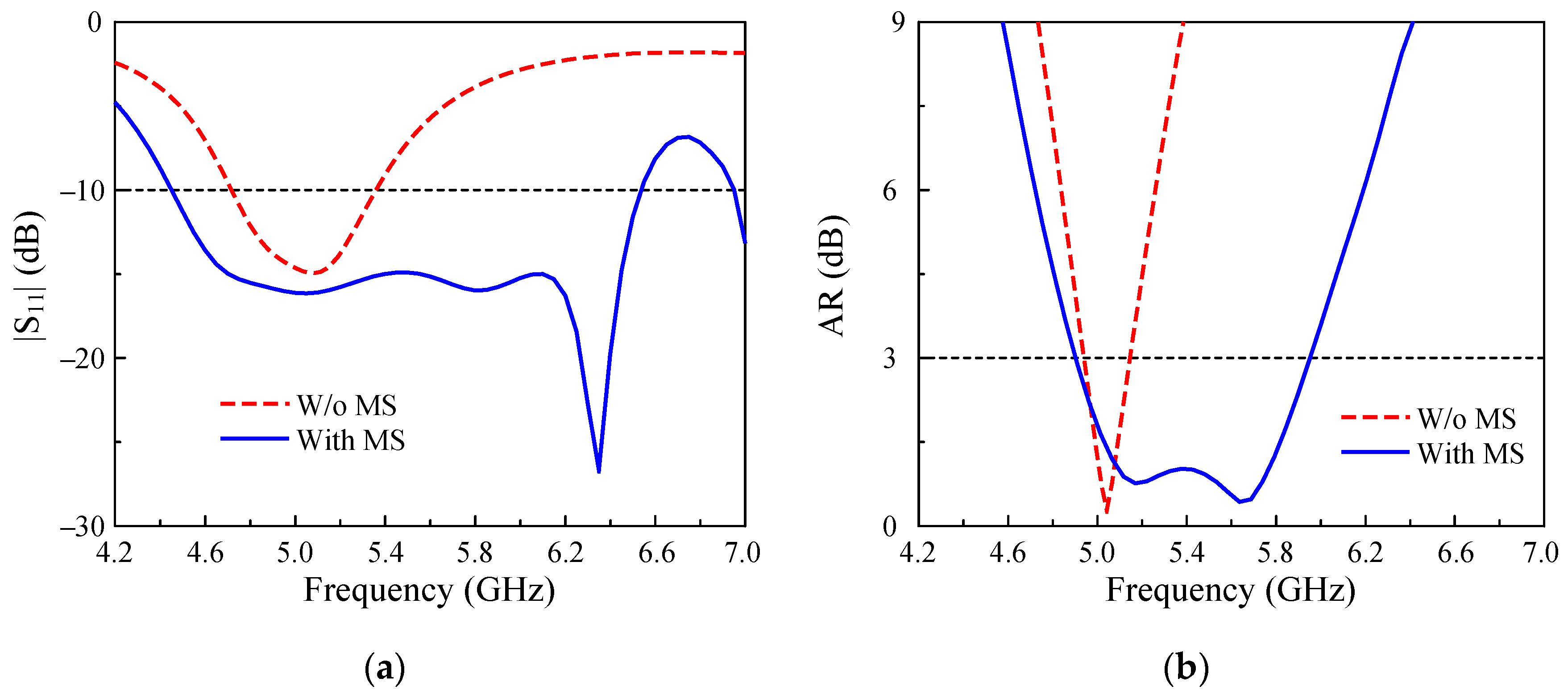
Since the principle for wideband operation has been thoroughly investigated in [26,27], it is therefore mentioned only briefly in this paper. In general, the wideband is attained by combining the operation of two adjacent bands. Here, the primary radiating patch operates in the lower frequency band. Meanwhile, the higher band is produced by a surface wave propagating on the MS. Figure 2 shows the simulated reflection coefficient (|S11|) and axial ratio (AR) results of the single CP antenna shown in Figure 1. It can be clearly observed that this design exhibits wideband operation of 19.3%, ranging from 4.9 to 5.95 GHz. Note that this frequency range is an overlap between the −10 dB |S11| and the 3-dB AR BWs.

3. Two-Element MIMO Antenna

3.1. Antenna Geometry

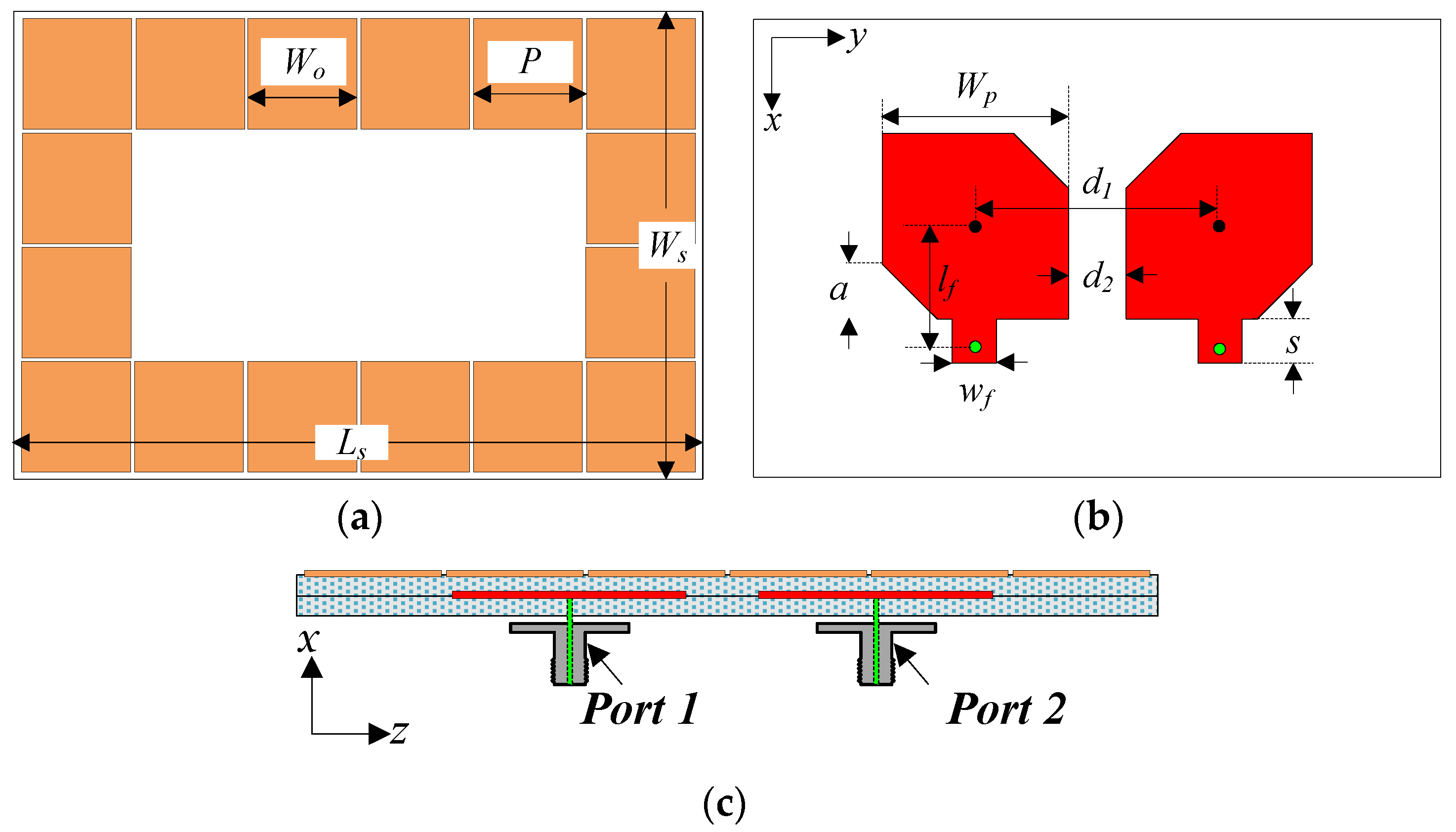
Figure 3 shows the detailed configurations of the proposed two-element MIMO antenna. The MIMO elements are two square patches whose corners are truncated in different manners for polarization diversity. Here, the left element is excited by Port-1 and radiates RHCP waves. The right element with Port-2 excitation produces LHCP waves. To improve the antenna’s performance, an array of metallic plates is positioned periodically around the MIMO elements. Note that the MIMO elements and the MS are located in different layers.

3.2. Antenna Design Procedure

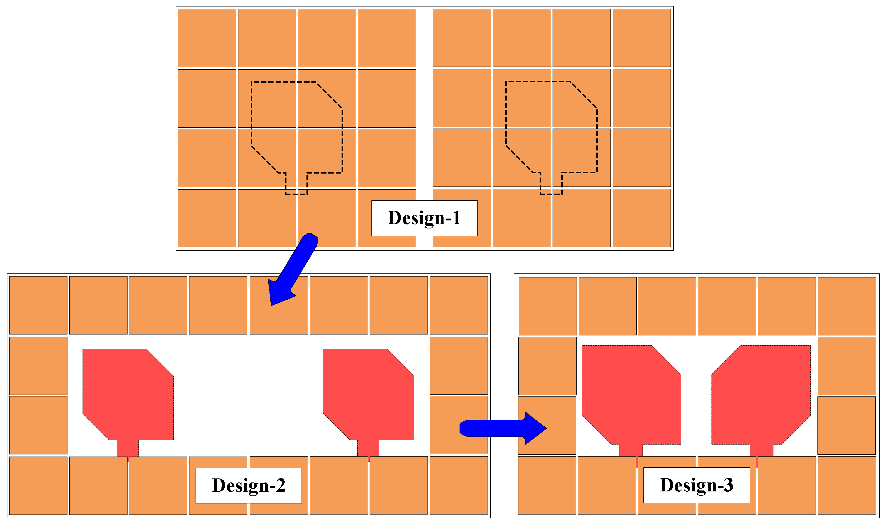
The design process for the final realization of the proposed antenna is given in Figure 4. It is noted that to make a fair comparison, Design-1, -2, and -3 are optimized so that the isolation within the operating BW is always higher than 20 dB. In addition, the antenna’s size is calculated based on the lowest operating frequency (λL).
The operation characteristics in terms of reflection coefficient |S11|, transmission coefficient |S21|, and AR of the abovementioned designs are illustrated in Figure 5. First, Design-1 is a combination of two elements with a full configuration of MS. In this case, the center-to-center spacing between the MIMO elements, at 34 mm, is very wide, equivalent to 0.54λL. This antenna provides a wide operating BW of 17.1% (4.8–5.7 GHz). In this design, the port isolation is always better than 20 dB across this band. Despite having wideband operation, the element spacing of Design-1 is very wide. To tackle this deficiency, the MS is modified as Design-2. Here, several unit cells at the center are removed. The element spacing in this case is 32 mm, which is about 0.53λL. In fact, this spacing is slightly less than that of Design-1. However, Design-2 can perform higher isolation within the operating BW. The figure for Design-2 is 24 dB compared with 20 dB in Design-1. Moreover, the operating BW of Design-2 is smaller than that of Design-1, which is about 11.3% (5.0–5.6 GHz). Finally, the number of unit cells is reduced in Design-3. As observed in Figure 5, Design-3 operates from 5.0 to 5.6 GHz, which is similar to Design-2. However, the configuration in Design-3 significantly reduces the center spacing to 24.6 mm, corresponding to approximately 0.41λL.
To explain the function of MS in a mutual coupling reduction, a current distribution comparison between Design-3 and a referee antenna is implemented. The referee design is a MIMO antenna with only two square patches. This design has a similar edge-to-edge spacing as that of Design-3 and the operating band as well. Figure 6 illustrates the current distribution of Design-3 and the referee design at 5.2 GHz. It can be seen that when Port-1 is excited, there is a strong induced current on the non-excited patch. Therefore, this design suffers from extremely high mutual coupling. With the presence of MS, the current is redistributed, and it is highly concentrated on the excited patch and the surrounding unit cells. Meanwhile, the current on the non-excited patch is insignificant, leading to high isolation. Based on these results, the effectiveness of the proposed MS in mutual coupling reduction has been obviously demonstrated.
Finally, the CP realization of the proposed antenna is presented in Figure 7. In this case, the antenna is excited in Port-1 and the current distribution at 5.2 GHz is chosen to present. When the phase changes from 0° to 270°, the direction of the vector current is changed accordingly. Here, the vector current rotates in a counter-clockwise direction, leading to RHCP radiation.

3.3. Key Parameter Studies

To provide a better understanding about the antenna’s optimization process, the parameter studies are implemented. For each study, only one parameter is changed while the others are fixed at optimal values provided in Section 3.1.
First, the impedance matching of the proposed antenna can be independently controlled by tuning the feeding position, lf. Figure 8 shows the simulated reflection coefficient |S11|, transmission coefficient |S21| and the AR for different values of lf. As seen, lf only has significant influence on the matching performance. Meanwhile, the |S21| and the AR values are quite stable against the variation in this parameter.
Secondly, the AR performance of the proposed design is considered. In this case, the corner truncation, a, is the critical parameter to determine the AR value. As shown in Figure 9, tuning a leads to a considerable change in the AR values. The antenna only exhibits good AR with an appropriate value of a. In contrast, the S-parameter remains unchanged regardless of the variation of a.
Finally, the isolation of the proposed MIMO antenna is controlled by adjusting the distance between the primary radiating elements, d1. As shown in Figure 10, when d1 increases the isolation is improved. Additionally, since the operation of the higher CP band is produced by the MS, changing the position of the radiating source leads to a different coupling scenario between the patch and the MS. This will affect the AR and S-parameter characteristics.

3.4. Optimization Process

According to the key parameter studies discussed in Section 3.2, the antenna optimization process can be briefly summarized as follows:
  • Step 1: Design a single element based on ref [26].
  • Step 2: Remove all the center unit cells of the MS.
  • Step 3: Tune the feeding position, lf, to optimize the impedance matching.
  • Step 4: Tune the truncated corner, a, to optimize the AR.
  • Step 5: Tune the distance between the MIMO element, d2, to optimize the isolation.
  • Step 6: Fine-tune all parameters to produce the best performance.

4. Measured Results

An antenna prototype is fabricated and tested to verify the design concept. Figure 11 shows photographs of the fabricated antenna at different layers. The Scattering parameter (S-parameter) is tested in open-air environments using a PNA Network Analyzer N5224A. Meanwhile, the far-field parameters are characterized in an anechoic chamber.

4.1. S-Parameter Results

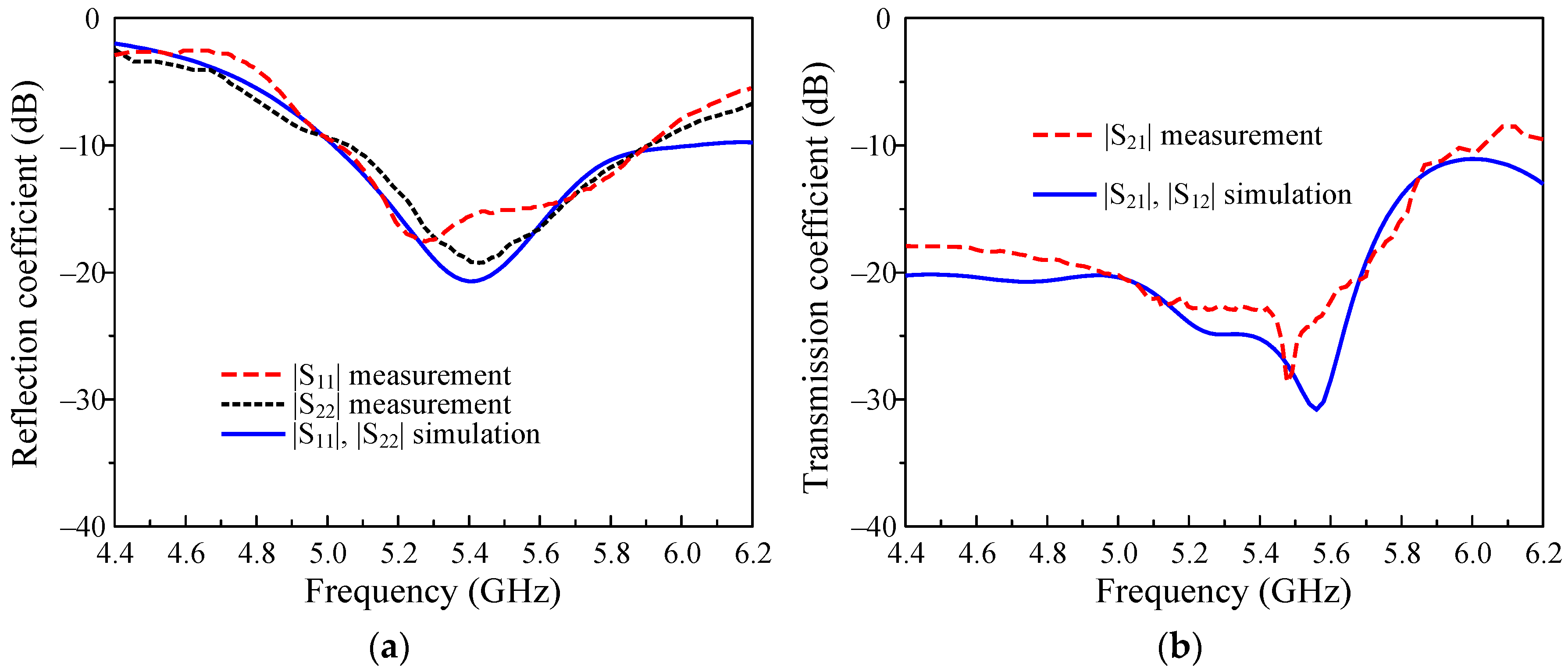
The simulated and measured reflection coefficients |S11| and transmission coefficients |S21| of the proposed MIMO antenna are presented in Figure 12. The measured data show that the proposed design has wide impedance BW from 5.05 to 5.9 GHz, corresponding to 15.5%. In addition, the measured |S21| is higher than 20 dB in the frequency range from 4.95 to 5.7 GHz.

4.2. Far-Field Results

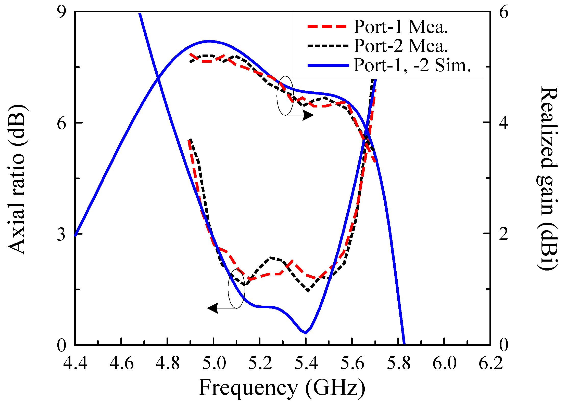
The simulated and measured ARs and realized gains in the broadside direction (+z) are shown in Figure 13. For far-field measurements, when one port is excited, the other port is terminated with a 50-Ω load. The measured data demonstrate that the antenna performs wide 3-dB AR BW of 11.3%, ranging from 5.0 to 5.6 GHz. This band is fully covered by the −10 dB impedance BW. In addition, the measured broadside gain is higher than 4.4 dBi across this operating band.
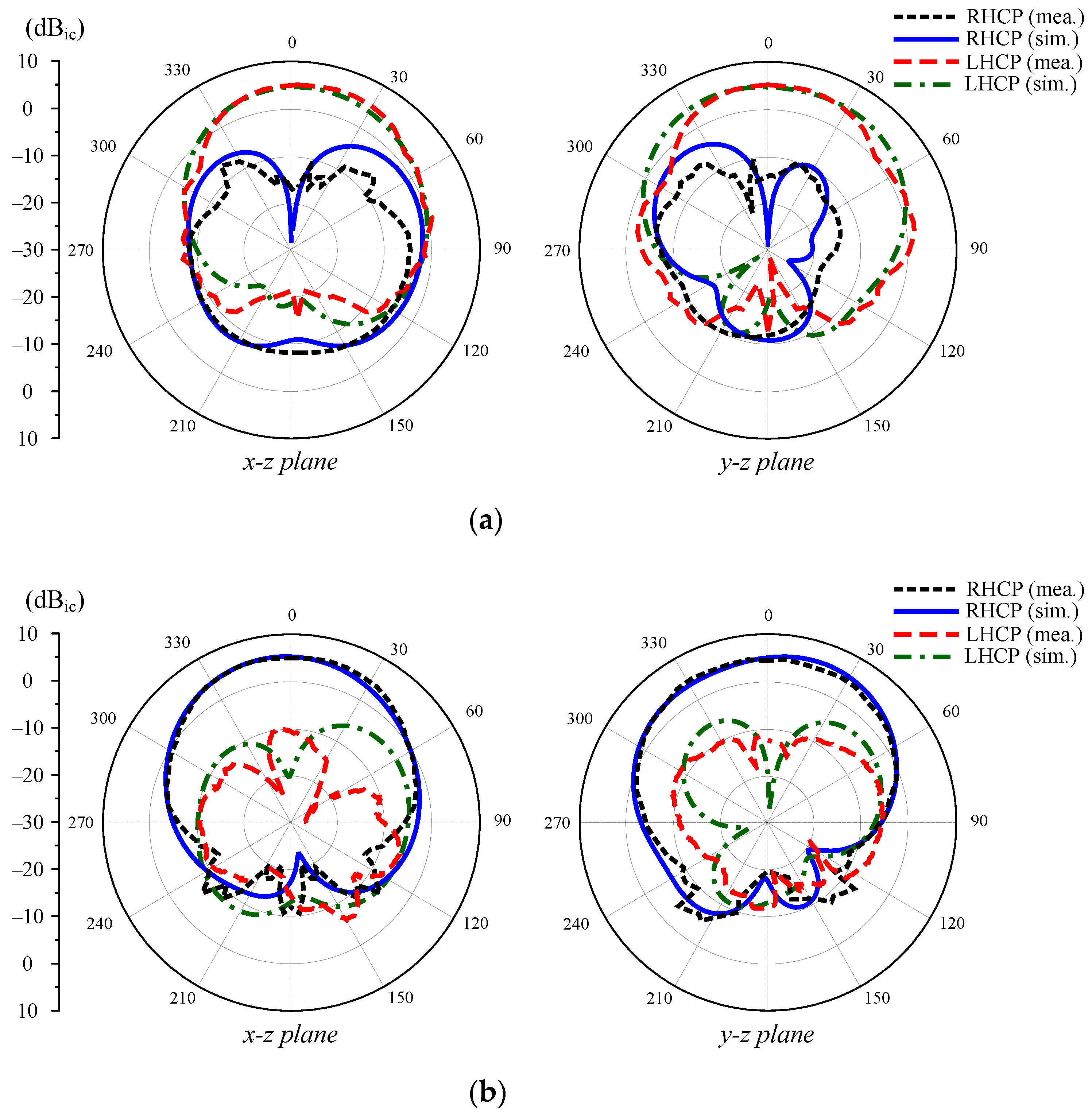
Next, the gain radiation patterns for two principal planes (x-z and y-z) are plotted in Figure 14. Due to the symmetrical geometry, the radiation patterns are almost identical when Port-1 and Port-2 are excited. Thus, only the patterns at 5.2 GHz with Port-1 excitation and 5.4 GHz with Port-2 excitation are plotted for brevity. The data indicates that dual sense CP is realized depending on the excitation port. The cross-polarization discrimination (difference between the co-polarization and cross-polarization gains) in the main direction (+z) is higher than 15 dB. The front-to-back ratio (difference between the maximum gains in +z and −z directions) is also higher than 13 dB.

4.3. MIMO Parameters

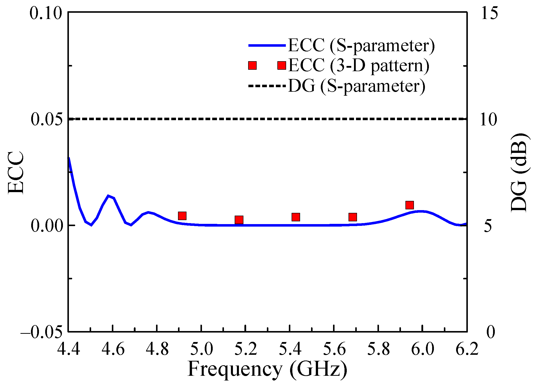
To evaluate the diversity performance, the envelop correlation coefficient (ECC) and the diversity gain (DG) are considered. The ECC demonstrates the independence of each MIMO element. Meanwhile, the DG shows the power lost in transmission when diversity schemes are performed. The ECC and the DG are calculated based on S-parameters and radiation patterns as seen in Equations (1)–(3) [28,29]:
ρ e i j = S i i S i j + S j i S j j 2 ( 1 S i i 2 S i j 2 ) ( 1 S j i 2 S j j 2 )
ρ e i j = | 0 4 π [ R i θ ,   φ × R j θ ,   φ   ] d Ω | 2 0 4 π | R i θ ,   φ | 2 d Ω 0 4 π | R j θ ,   φ | 2 d Ω  
D G = 10   1 + ρ e i j 2
Here, S i i and S i j in Equation (1) are the reflection coefficients and transmission coefficients, respectively. The Ω in Equation (2) is the solid angle of the 3D radiation patterns R i θ ,   φ and R j θ ,   φ . The ECC and DG values of the proposed antenna are calculated and depicted in Figure 15. It can be seen that the ECC of the proposed antenna is significantly lower than the standard value of 0.5. Meanwhile, the calculated DG value is approximately equal to 10 dB. These results demonstrate the satisfactory MIMO performance of the proposed antenna.

4.4. Performance Comparison

Table 1 compares the MIMO antennas using microstrip patch structure. The BW is defined so that the |S11| is less than −10 dB, the |S21| is lower than 20 dB, and the AR is smaller than 3 dB. As observed, the designs in [16,20] have a narrow BW as no wideband technique is employed. Compared to [21,22], the proposed design has similar operating BW, but smaller lateral dimensions. Most important is the comparison of the MIMO antennas using a similar method. Despite having better BW, the element spacing of the designs in [24] is significantly larger than that of the reported design which is more than four times bigger. Note that the gain of the proposed antenna is less than the others, which could be attributed to the asymmetric, small-footprint structure.

5. Conclusions

An MS-based wideband MIMO CP antenna has been presented in this paper. Unlike the current reported MS-based MIMO designs, in which wide element spacing is required for mutual coupling reduction, the proposed MS is modified by removing proper unit cells. Thus, high isolation can be attained with small element spacing. The fabricated antenna prototype has isolation higher than 20 dB over the operating BW from 5.0 to 5.6 GHz. The realized gain across this band is always higher than 4.4 dBi. Additionally, good diversity performance is also achieved by the proposed design through the investigation of several MIMO parameters such as ECC and DG. In comparison with the related works, the presented antenna has the advantages of wideband operation while achieving high isolation and small overall size. The proposed design is a promising candidate for applications in C-band such as WLAN and satellite communications.

Author Contributions

Conceptualization and writing—review and editing, H.-H.T.; software, investigation and writing—original draft preparation, T.T.-L.N. and T.D.P. All authors have read and agreed to the published version of the manuscript.

Funding

This research received no external funding.

Data Availability Statement

Contact to corresponding author for research data.

Conflicts of Interest

The authors declare no conflict of interest.

References

  1. Murch, R.; Letaief, K. Antenna systems for broadband wireless access. IEEE Commun. Mag. 2002, 40, 76–83. [Google Scholar] [CrossRef] [Green Version]
  2. Ding, Y.; Leung, K.W. Dual-band circularly polarized dual-slot antenna with a dielectric cover. IEEE Trans. Antennas Propag. 2009, 57, 3757–3764. [Google Scholar] [CrossRef]
  3. Kulkarni, J.; Alharbi, A.G.; Sim, C.Y.D.; Elfergani, I.; Anguera, J.; Zebiri, D.; Rodriguez, J. Dual Polarized, Multiband Four-Port Decagon Shaped Flexible MIMO Antenna for Next Generation Wireless Applications. IEEE Access 2022, 10, 128132–128150. [Google Scholar] [CrossRef]
  4. Kollipara, V.; Peddakrishna, S. Quad-Port Circularly Polarized MIMO Antenna with Wide Axial Ratio. Sensors 2022, 22, 7972. [Google Scholar] [CrossRef]
  5. Saxena, S.; Kanaujia, B.K.; Dwari, S.; Kumar, S.; Tiwari, R. A compact dual-polarized MIMO antenna with distinct diversity performance for UWB applications. IEEE Anten. Wirel. Propag. Lett. 2017, 16, 3096–3099. [Google Scholar] [CrossRef]
  6. Kumar, S.; Nandan, D.; Srivastara, K.; Kumar, S.; Singh, H.; Marey, M.; Mostafa, H.; Kanaujia, B.K. Wideband circularly polarized textile MIMO antenna for wearable devices. IEEE Access 2021, 9, 108601–108613. [Google Scholar] [CrossRef]
  7. Iqbal, A.; Smida, A.; Alazemi, A.L.; Waly, M.I.; Mallat, N.K.; Kim, S. Wideband circularly polarized MIMO antenna for high data wearable biotelemetric devices. IEEE Access 2020, 8, 17935–17944. [Google Scholar] [CrossRef]
  8. Chaudhuri, S.; Kshetrimayum, R.S.; Sonkar, R.K. High inter-port isolation dual circularly polarized slot antenna with split-ring resonator based novel metasurface. AEU-Int. J. Electron. Commun. 2019, 107, 146–156. [Google Scholar] [CrossRef]
  9. Kulkarni, J.; Sim, C.Y.D.; Gangwar, R.K.; Anguera, J. Broadband and Compact Circularly Polarized MIMO Antenna With Concentric Rings and Oval Slots for 5G Application. IEEE Access 2022, 10, 29925–29936. [Google Scholar] [CrossRef]
  10. Iqbal, G.; Illahi, A.; Sulaiman, M.I.; Alam, M.M.; Su’ud, M.M.; Yasin, M.N.M. Mutual coupling reduction using hybrid technique in wideband circularly polarized MIMO antenna for WiMAX applications. IEEE Access 2019, 7, 40951–40958. [Google Scholar] [CrossRef]
  11. Chen, H.N.; Song, J.M.; Park, J.D. A compact circularly polarized MIMO dielectric resonator antenna over electromagnetic band-gap surface for 5G applications. IEEE Access 2019, 7, 140889–140898. [Google Scholar] [CrossRef]
  12. Hu, Y.; Pan, Y.M.; Di Yang, M. Circularly Polarized MIMO Dielectric Resonator Antenna with Reduced Mutual Coupling. IEEE Trans. Antennas Propag. 2020, 69, 3811–3820. [Google Scholar] [CrossRef]
  13. Hussain, N.; Jeong, M.J.; Park, J.; Kim, N. A broadband circularly polarized fabry-perot resonant antenna using a single-layered PRS for 5G MIMO applications. IEEE Access 2019, 7, 42897–42907. [Google Scholar] [CrossRef]
  14. Akbari, M.; Ali, M.; Farahani, M.; Sebak, A.; Denidni, T. Spatially mutual coupling reduction between CP-MIMO antennas using FSS superstrate. Electron. Lett. 2017, 53, 516–518. [Google Scholar] [CrossRef]
  15. Yang, W.J.; Pan, Y.M.; Zheng, S.Y. Mutual Coupling Reduction in CP MIMO Crossed-Dipole Antenna Array. IEEE Anten. Wirel. Propag. Lett. 2022, 21, 2442–2446. [Google Scholar] [CrossRef]
  16. Jamal, M.Y.; Li, M.; Yeung, K.L. Isolation enhancement of closely packed dual circularly polarized MIMO antenna using hybrid technique. IEEE Access 2020, 8, 11241–11247. [Google Scholar] [CrossRef]
  17. Alnahwi, F.M.; Al-Yasir, Y.I.A.; See, C.H.; Abd-Alhameed, R.A. Single-Element and MIMO Circularly Polarized Microstrip Antennas with Negligible Back Radiation for 5G Mid-Band Handsets. Sensors 2022, 22, 3067. [Google Scholar] [CrossRef]
  18. Gao, D.; Cao, Z.X.; Fu, S.D.; Quan, X.; Chen, P. A Novel Slot-Array Defected Ground Structure for Decoupling Microstrip Antenna Array. IEEE Trans. Antennas Propag. 2020, 68, 7027–7038. [Google Scholar] [CrossRef]
  19. Nayan, M.K.A.; Jamlos, M.F.; Jamlos, M.A. MIMO circular polarization array antenna with dual coupled 90 phased shift for point-to-point application. Microw. Opt. Technol. Lett. 2015, 57, 809–814. [Google Scholar] [CrossRef]
  20. Sufian, M.A.; Hussain, N.; Lee, J.; Park, S.G.; Kim, N. Mutual coupling reduction of a circularly polarized MIMO antenna using parasitic elements and DGS for V2X communications. IEEE Access 2022, 10, 56388–56400. [Google Scholar] [CrossRef]
  21. Tran, H.H.; Hussain, N.; Park, H.C.; Nguyen-Trong, N. Isolation in dual-sense CP MIMO antennas and role of decoupling structures. IEEE Antennas Wireless Propag. Lett. 2022, 21, 1203–1207. [Google Scholar] [CrossRef]
  22. Hussain, N.; Pham, T.D.; Tran, H.-H. Circularly Polarized MIMO Antenna with Wideband and High Isolation Characteristics for C-Band Communication Systems. Micromachines 2022, 13, 1894. [Google Scholar] [CrossRef] [PubMed]
  23. Tariq, S.; Naqvi, S.I.; Hussain, N.; Amin, Y. A metasurface-based MIMO antenna for 5G millimeter-wave applications. IEEE Access 2021, 9, 51805–51817. [Google Scholar] [CrossRef]
  24. Hussain, N.; Jeong, M.J.; Abbas, A.; Kim, N. Metasurface-based single-layer wideband circularly polarized MIMO antenna for 5G milimeter-wave systems. IEEE Access 2020, 8, 130293–130304. [Google Scholar] [CrossRef]
  25. Hasan, M.; Islam, M.T.; Samsuzzaman, M.; Baharuddin, M.H.; Soliman, M.S.; Alzamil, A.; Abu Sulayman, I.I.; Islam, M. Gain and isolation enhancement of a wideband MIMO antenna using metasurface for 5G sub-6 GHz communication systems. Sci. Rep. 2022, 12, 9433. [Google Scholar] [CrossRef]
  26. Ta, S.X.; Park, I. Low-profile broadband circularly polarized patch antenna using metasurface. IEEE Trans. Antennas Propag. 2015, 63, 5929–5934. [Google Scholar] [CrossRef]
  27. Tran, H.H.; Bui, C.D.; Nguyen-Trong, N.; Nguyen, T.K. A wideband non-uniform metasurface-based circularly polarized reconfigurable antenna. IEEE Access 2021, 9, 42325–42332. [Google Scholar] [CrossRef]
  28. Sharawi, M.S. Current misuses and future prospects for printed multiple-input, multiple-output antenna systems. IEEE Antennas Propag. Mag. 2017, 59, 162–170. [Google Scholar] [CrossRef]
  29. Amjad, I.; Saraereh, O.A.; Ahmad, A.W.; Bashir, S. Mutual coupling reduction using F-shaped stubs in UWB-MIMO antenna. IEEE Access 2018, 6, 2755–2759. [Google Scholar]
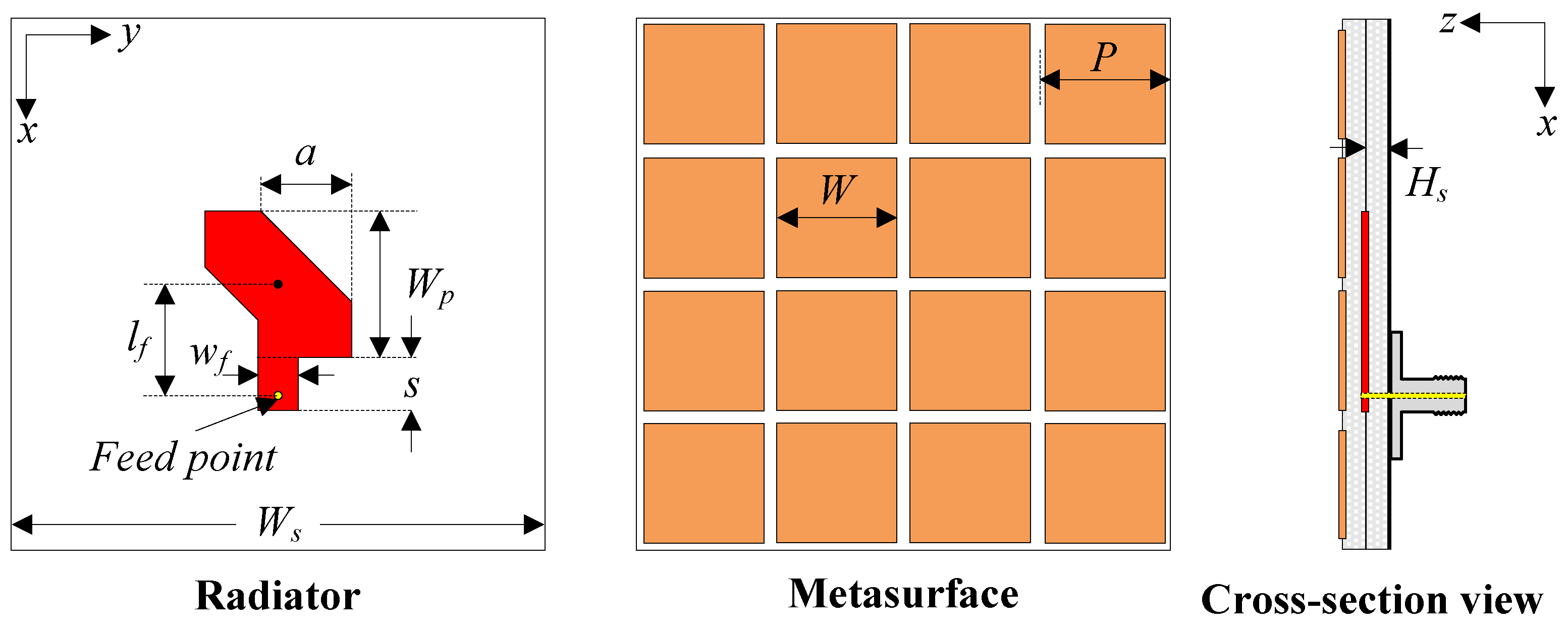
Figure 1. Geometry of single wideband MS based antenna. The optimal antenna’s dimensions are: Ws = 40 mm, Hs = 1.52 mm, Wp = 13 mm, a = 7 mm, lf = 8.5 mm, wf = 3 mm, s = 4 mm, P = 8 mm, W = 7.5 mm.
Electronics 12 00384 g001
Figure 2. Simulated performance of a single MIMO element (shown in Figure 1). (a) Reflection coefficient (|S11|), (b) axial ratio (AR).
Electronics 12 00384 g002
Figure 3. Geometry of the proposed MIMO CP antenna. (a) Top layer, (b) middle layer, and (c) cross-section view. The final parameters are Ls = 49.2 mm, Ws = 32.8 mm, Hs = 1.52 mm, Wp = 13.3 mm, a = 4.2 mm, lf = 9.3 mm, wf = 3 mm, s = 3.2 mm, P = 8.2 mm, W = 8 mm, d1 = 18 mm, d2 = 4.7 mm.
Electronics 12 00384 g003
Figure 4. Different configurations of MIMO CP antennas with MS.
Electronics 12 00384 g004
Figure 5. Simulated performance of different MIMO antennas. (a) Reflection coefficient (|S11|), (b) transmission coefficient (|S21|), and (c) axial ratio (AR).
Electronics 12 00384 g005
Figure 6. Simulated current distributions at 5.2 GHz with different phase of 0° and 90°.
Electronics 12 00384 g006
Figure 7. Simulated vector current distributions at 5.2 GHz for the proposed MIMO antenna with Port-1 excitation.
Electronics 12 00384 g007
Figure 8. Simulated performance of the proposed MIMO antenna with different values of lf. (a) Reflection coefficient (|S11|), (b) transmission coefficient (|S21|), and (c) axial ratio (AR).
Electronics 12 00384 g008aElectronics 12 00384 g008b
Figure 9. Simulated performance of the proposed MIMO antenna with different values of a. (a) Reflection coefficient (|S11|), (b) transmission coefficient (|S21|), and (c) axial ratio (AR).
Electronics 12 00384 g009
Figure 10. Simulated performance of the proposed MIMO antenna with different values of d1. (a) Reflection coefficient (|S11|), (b) transmission coefficient (|S21|), and (c) axial ratio (AR).
Electronics 12 00384 g010
Figure 11. Photographs of fabricated proposed MIMO CP antenna.
Electronics 12 00384 g011
Figure 12. Simulated and measured S-parameter of the proposed MIMO antenna. (a) Reflection coefficient (|S11|), (b) transmission coefficient (|S21|).
Electronics 12 00384 g012
Figure 13. Simulated and measured AR results of the proposed MIMO CP antenna.
Electronics 12 00384 g013
Figure 14. Simulated and measured radiation patterns of the proposed MIMO CP antenna. (a) 5.2 GHz with Port-1 excitation, (b) 5.4 GHz with Port-2 excitation.
Electronics 12 00384 g014
Figure 15. Calculated ECC and DG of the proposed antenna.
Electronics 12 00384 g015
Table 1. Comparison among MIMO CP antennas using microstrip patch structure.
Ref.No. of
Elements
CP
Technique
Wideband
Technique
Overall Size
(λL)
Spacing
(λL)
BW
(%)
Gain
(dBi)
[16]2Offset feedNone1.25 × 0.83 × 0.010.061.95.8–6.1
[20]4TC 1 patchNone1.44 × 1.44 × 0.030.172.07.6–7.7
[21]2Diagonal slotPE0.95 × 0.71 × 0.050.098.34.0–6.2
[22]2TC 1 patchPE1.41 × 0.97 × 0.050.0811.36.0–8.5
[24]4TC 1 patchMS1.83 × 1.83 × 0.050.3616.810.8–11.0
Prop.2TC 1 patchMS0.82 × 0.55 × 0.050.0811.34.4–5.2
TC 1: Truncated corner.
Disclaimer/Publisher’s Note: The statements, opinions and data contained in all publications are solely those of the individual author(s) and contributor(s) and not of MDPI and/or the editor(s). MDPI and/or the editor(s) disclaim responsibility for any injury to people or property resulting from any ideas, methods, instructions or products referred to in the content.