Article

A Beamforming-Based Enhanced Handover Scheme with Adaptive Threshold for 5G Heterogeneous Networks

China Telecom Research Institute, Beijing 102209, China
*
Author to whom correspondence should be addressed.
Current address: China Telecom Beijing Information Technology Innovation Park, Beiqijia Town, Changping District, Beijing 102209, China.
Electronics 2023, 12(19), 4131; https://doi.org/10.3390/electronics12194131
Submission received: 6 September 2023 / Revised: 1 October 2023 / Accepted: 2 October 2023 / Published: 3 October 2023
(This article belongs to the Special Issue 5G Mobile Telecommunication Systems and Recent Advances)

Abstract

:
In order to tackle the explosive growth of data traffic and the number of terminals, 5G heterogeneous network (HetNet) has become an important evolution direction of 5G networking architecture. Densely deployed micro base stations (gNBs) in 5G HetNets will dramatically increase the handover frequency of user equipment (UE), resulting in more handover failures, and seriously reducing the user experience of mobile UE. Aiming at tackling this problem, this paper proposes a beam enhancement handover scheme with an adaptive threshold. Firstly, different beamforming gains are configured for the mobile UE in the overlapping area of two gNBs to improve the signal strength received by the UE at the edge of gNB coverage. Secondly, for mobile UE with different speeds, adaptive handover decision parameters are configured, and reference signal receiving strength (RSRP) as well as reference signal receiving quality (RSRQ) are used for joint handover decisions to achieve reliable handover. The simulation results verify that the proposed scheme can effectively improve the signal strength of the edge area, and the adaptive joint handover decision algorithm based on UE speed can also effectively improve the handover success probability.

1. Introduction

The 5G heterogeneous network (HetNet) is considered to be one of the most effective solutions for current network technical challenges, and can provide seamless and high-speed communication services for user equipment (UE) [1,2,3,4]. By superimposing macro-cellular base stations with another layer of densely deployed 5G micro base stations (gNBs), 5G HetNets can significantly increase system capacity and improve communication link reliability. As one of the core operations of 5G HetNets, handover plays an important role in satisfying the communication requirements of ultra-high availability and reliability of a 5G network [5,6,7]. Handover mainly occurs when a UE moves in between two cells during connected mode, which is intended to preserve the connection received by the UE [8,9]. In the communication scenario with intensive gNB deployment, high-reliability and low-latency handover is one of the prerequisites for 5G networking. In traditional cellular networks, the frequency band lower than 6 GHz (sub-6 GHz) has excellent electromagnetic characteristics, so operators generally choose this frequency band to provide a reliable quality of service (QoS) [10,11]. However, at present, the sub-6GHz frequency band has almost been used up, so it is difficult to further increase the transmission rate in 5G HetNets [12,13]. Millimeter wave has rich spectrum resources and can provide a large amount of the spectrum to meet the requirements of future cellular network capacity growth [14,15,16]. The distinctive feature of the 5G NR, which is clearly distinguished from the third-generation partnership project (3GPP) long-term evolution (LTE), is the utilization of ultra wide bandwidth and beamforming using massive multiple-input multiple-output (MIMO) operating in the ultra-high frequency band with millimeter wave length [17,18].
The introduction of millimeter wave for 5G HetNets can effectively increase system capacity and alleviate the interference between different network layers [19,20]. However, millimeter wave has a relatively high path loss and is very sensitive to atmospheric attenuation and rain decline, which greatly reduces the effective coverage of millimeter-wave (mmWave) base stations, and thus leads to the increase in UE handover frequency and link outage probability [21,22,23]. At the same time, in order to make better use of network resources of the millimeter-wave band, beamforming technology is adopted in 5G networks to provide a certain gain for millimeter-wave signals, so as to compensate for signal fading and enhance the anti-jamming ability of the signals from the edge coverage [24,25,26]. UE can select the most appropriate beam and establish the directional communication link through a beam sweeping procedure, which is one of the key characteristics of the 5G system operating in millimeter-wave band [27,28]. Due to the small coverage area of the millimeter-wave gNBs and the relatively low speed of UE in the hotspot area, the gNB can easily obtain the location and speed of the UE, and then calculate the arrival direction and other beamforming parameters to provide certain beamforming gains for the UE. Beamforming technology can be applied to provide beamforming gain for UE in the overlapping area of two millimeter-wave gNBs by using the UE characteristics such as moving speed and position information, so as to achieve a more accurate handover decision, avoid ping-pong handover, and improve system reliability.

1.1. Literature Review

In 3GPP standard, the traditional handover decision is triggered by A3 events, which can be specifically understood as a higher reference signal receiving power (RSRP) of the target cell than the RSRP of the current serving cell for a fixed threshold value [29,30]. RSRP is a key physical layer measurement parameter representing wireless signal strength. It refers to the average power of the reference signal received by the UE from the base station within the measured bandwidth range [31,32]. RSRP can accurately reflect the signal strength received by the UE at a certain location within the coverage range of the base station. However, the effective coverage range of the millimeter-wave base station is greatly reduced, and the RSRP values of two adjacent millimeter-wave gNBs may be close, but using RSRP as the handover criterion may cause that handover cannot be triggered in time.
In addition, due to the rapid attenuation of a millimeter-wave signal, when the speed of the UE is high, the RSRP decision algorithm will easily lead to ping-pong handover. For providing a better connectivity and lower outage probability, a soft handover scheme named the double-beam soft handover has been designed for the mmWave UAV system by the authors of [33]. The handover scheme in this paper can be regarded as a relatively soft handover, where the source communication link is released by UE after completing the new link with the new base station so as to achieve a lower outage probability. However, soft handover will increase the computing burden and signaling overhead of base stations and UE, and will increase the complexity of the network. Therefore, in the 4G (LTE) and 5G (NR) networks of the 3GPP R15 version, the handover of UE is usually first disconnected from the source cell and then established with the target cell, that is, hard handover. The authors of [34] proposed a joint handover trigger algorithm based on the location, speed, and RSRP of UE. Handover will be triggered when the UE passes the middle point of the overlapping region, which improves the handover success probability. The authors of [35] leverage machine learning tools and propose a novel solution for the reliability and latency challenges in mmWave MIMO systems. In the developed solution, the base stations learn how to predict whether a certain link will experience blockage in the next few time frames, using their observations of adopted beamforming vectors. This allows the serving base station to proactively handover the user to another base station with a highly probable LOS link. The authors of [36] proposed a handover method based on fuzzy logic control and Kalman filter. In the handover decision phase, the received signal strength (RSS), network load, UE speed, data transmission rate, and other related parameters were comprehensively considered, and the fuzzy logic effect function was given to make the handover decision. A reasonable adjustment of handover parameters can effectively reduce the number of ping-pong handovers, a too early handover, and a too late handover. Tarek Al Achhab proposed a robust algorithm, analyzed the relationship between hysteresis threshold and trigger time through an innovative mechanism, adaptically set the control parameters of handover, minimized unnecessary handover, and provided a new idea for the research of handover in HetNets [37]. The authors in [38] proposed an adaptive trigger scheme for handover, which can predict the received signal strength index and ensure that handover can be triggered accurately and timely when the terminal is moving. In view of the short coverage range of single access point and the large overlapping range of coverage areas of different networks in HetNets, the authors of [39] proposed a handover skip scheme based on RSRP and its changing rate, and adopted an adaptive network preference to effectively reduce the number of unnecessary handover. Rasha El Banna proposed an adaptive adjustment algorithm for handover parameters based on fuzzy logic control [40]. This scheme dynamically adjusts the best trigger time in the process of handover according to the speed of the UE and the size of cells, so as to reduce the number of handover failures and ping-pong handover. The authors of [41] also applied the idea of fuzzy logic and used user speed and wireless channel quality parameters to adjust the hysteresis threshold of the handover strategy in a self-optimizing way, so as to reduce the number of redundant handovers and the probability of handover failure. The proposed algorithm in [42] estimated handover parameter settings based on the weight function, which depends on three bounded functions and the weight of each bounded function. The authors of [43] proposed a joint handover decision algorithm based on RSRP and reference signal receiving quality (RSRQ). The quality of the communication link can be well demonstrated by RSRQ. Using RSRQ as the parameter of handover decision to assist the RSRP decision algorithm, RSRP can realize the correct triggering of handover in the scenario where the accuracy of RSRP decision decreases, thus improving the robustness of the system. The adaptive joint handover decision algorithm in [44] is realized via a genetic algorithm. Based on the genetic algorithm, the dynamic hysteresis threshold that meets the requirement of fast handover at different moving speeds is achieved by optimizing the handover parameters, thus achieving a higher probability of communication satisfaction.

1.2. Motivation and Contributions

At present, the adjustment of handover parameters mostly focuses on multi-attribute joint decision and is devoted to the optimization of vertical handover between different network schemes. Moreover, the fuzzy logic control scheme for millimeter-wave signal will inevitably cause some decision errors and increase the instability of handover. There are at present only a few studies on the handover between two gNBs in 5G HetNets, and the study on how to configure suitable handover parameters for UE with different speeds is still insufficient.
Therefore, in this paper, we focus on the handover problem between two gNBs within the coverage area of an evolved Node B (eNB). The 5G millimeter-wave beamforming technology is used in the overlapping area of two gNBs to provide beamforming gains for the communication links when UE enter the overlapping area, improve the signal strength of the edge area covered by the gNB, and assist in the handover decision. At the same time, for UE with different speeds, the adaptive trigger thresholds of handover is configured for them, and the joint decision algorithm with RSRP and RSRQ is combined to improve the handover performance between gNBs. Our simulation results demonstrate the accuracy of the presented theoretical analysis. Furthermore, it is shown that the proposed scheme has a much better performance than the 5G traditional handover scheme.
The contents of this paper are organized as follows: Section 2 presents the system model. In Section 3, the technical details of the proposed handover scheme is analyzed. Section 4 presents the numerical simulation results and analysis. Lastly, the entire work is concluded in Section 5.

2. Network Architecture

This paper proposes a handover scheme for two gNBs in 5G HetNets. When th UE enters the overlapping area of two adjacent gNBs, one gNB will provide beamforming gain for the communication link between the UE and gNB based on the beamforming technology and the position information of the UE, so as to improve the signal quality of the UE. At the same time, the trigger thresholds of RSRP and RSRQ are dynamically adjusted according to the speed of the UE and the received signal quality. The joint decision algorithm is used to ensure the accurate triggering of the handover so as to improve the handover success probability between two gNBs.

2.1. System Model

The system model of the handover scheme proposed in this paper is shown in Figure 1. The network scenario is 5G non-standalone (NSA), namely a hybrid networking mode, where 4G eNB and 5G gNB coexist and multiple micro base stations are deployed in one macro base station. The UE moves from gNB a to gNB b, and 4G eNB uses omnidirectional antenna to transmit information in a 2 GHz band. Outside the overlapping area, gNB is in omnidirectional antenna mode and transmits in a 28 GHz frequency band. In the overlapping area, gNB is transmitted in a directional antenna mode.
Take gNB a as the origin of coordinates and the horizontal direction from gNB a to gNB b as the X-axis to establish the coordinate system. Then, the distance between two adjacent gNBs is d a b , the radius of gNB coverage area is r, and the length of the overlapping area is 2 r d a b .
When the UE enters the overlapping area of two adjacent gNBs, the gNB antenna switches from omnidirectional mode to directional mode, increasing the beamforming gain of the gNB link for the UE. In order to ensure the accurate triggering of handover, this section assumes that gNB a has two different beamforming gains in the directional antenna beamforming state. When the UE is on the left side of the center line in the overlapping area, the beamforming gain of the link between gNB a and the UE is G 1 . At this time, the transmitting power of gNB a needs to be reduced by G 1 to prevent handover misjudgment caused by RSS jumping. When the UE moves to the right side of the overlapping region, the beamforming gain of gNB a is adjusted to G 2 ( G 2 < G 1 ). For gNB b, the beamforming gain in the overlapping region is always maintained as G 2 . The beamforming gain scheme used in this section is shown in Table 1.
Based on the beamforming gain adjustment scheme, the signal strength received by the UE from gNB b will be improved due to the beamforming gain after the UE enters the overlapping area of two gNBs. When the UE passes through the midpoint of the overlapping area, the signal strength received from gNB a will be reduced due to the reduction in beamforming gain. In this way, the difference in signal quality between two gNBs can be further improved to ensure the accurate triggering of handover.
The coverage range of millimeter-wave gNB is much smaller than that of a 4G LTE base station. This paper mainly considers the scene of line of sight (LOS) in the coverage range of a gNB, and the multipath effect is not obvious, so the influence of multipath effect on a wireless link is not considered in this paper.

2.2. Adaptive Adjustment of Handover Threshold

In the 5G NSA scenario, due to the reduction in the coverage range of millimeter-wave gNBs, the time for a UE to pass through the overlapping area will also be reduced, and the attenuation of millimeter-wave signals will also lead to serious path propagation losses. Therefore, for terminals with different moving speeds, it is unreasonable to configure a fixed trigger handover threshold. This section proposes a method to dynamically adjust the trigger threshold of RSRP and RSRQ. In the 5G NSA networking scenario, the trigger handover threshold can be reasonably configured according to the location and speed of the UE.
When the UE is at a specific position x, the signal power difference between the source gNB a and the target gNB b received by the UE can be expressed as:
Δ = P t P L b , x ε 0 , σ b P t P L a , x ε 0 , σ a P L a , x P L b , x ,
where P L a , x and P L b , x are the path propagation losses from gNB a and gNB b to the UE, respectively; ε 0 , σ a and ε 0 , σ b are the shadow fading of the two links, respectively.
Assume that the speed of the UE is v m/s, and the time required to complete the handover is τ s. Generally, the length of the overlapping area of two adjacent gNBs should meet the requirement whereby a handover between two networks is able to be executed at least twice. If the overlapping area is too small, the UE may not be able to execute handover in time, resulting in communication interruption and other problems. If the overlapping area is too large, the UE will perform handover more frequently, which will seriously affect the user experience. Therefore, when the UE moves to the right edge of the overlapping area, the signal power difference received by the UE from two adjacent gNBs can be expressed as:
Δ = P t P L b , x + 2 τ v ε 0 , σ b P t P L a , x + 2 τ v ε 0 , σ a P L a , x + 2 τ v P L b , x + 2 τ v .
In order to adapt to the UE with different speeds, the handover trigger threshold of RSRP Γ r s r p is adjusted. The specific scheme can be expressed as:
Γ r s r p ( x ) = Γ + Δ Δ = Γ + P L a , x P L b , x P L a , x + 2 τ v + P L b , x + 2 τ v .
where Γ is a fixed value, indicating the handover trigger threshold based on the RSRP received by the UE from different gNBs. Through such an adjustment, when the UE moves through two adjacent gNB-overlapping regions at a relatively high speed and stays in the overlapping regions for a short time, a relatively small handover trigger threshold will be configured for the UE to ensure the timely triggering of handover. When the speed of the UE is low, it takes a relatively long time for the UE to traverse the overlapping area. Therefore, a higher threshold will be configured for the UE to avoid ping-pong handover.
The RSRQ adjustment is similar to the RSRP adaptive solution. If the RSRQ of the source—which gNB receives by the UE—is high, this indicates that the communication link from the source gNB is of good quality. The RSRQ threshold will be increased to limit the trigger of handover. On the contrary, if the RSRQ received by the UE from the source gNB is low, it indicates that the quality of the communication link is poor. Therefore, the threshold will be reduced to promote the trigger of handover, so that the UE can execute handover to the appropriate link.
According to the above narration, Δ h and Δ l are defined as the optimal channel quality and the worst channel quality, respectively; Γ h and Γ l are defined as the maximum and minimum RSRQ handover trigger thresholds, respectively. When the minimum trigger threshold is guaranteed, the mapping with Γ h and RSRQ is established. Finally, the maximum value of RSRQ threshold and Γ l will be taken as the RSRQ handover decision threshold after adaptive adjustment, which can be expressed as:
Γ r s r q = max Γ h min max R S R Q Δ l , 0 Δ h Δ l , 1 k , Γ l ,
where k represents a factor related to speed v, determining the changing rate of the handover trigger threshold Γ r s r q , so that the UE with a faster speed can quickly trigger the handover with a smaller RSRQ threshold, and the UE with a slower speed can ensure the stability of the source service gNB network with a larger RSRQ threshold, which can be expressed as:
k = 0.3 , 0 v < 5 0.5 , 5 v < 10 0.7 , 10 v < 15 0.9 , v 15 .
Thus, in the handover process, Γ r s r q can configure different values along with the changes of UE speed and position to realize the adaptive handover decision.

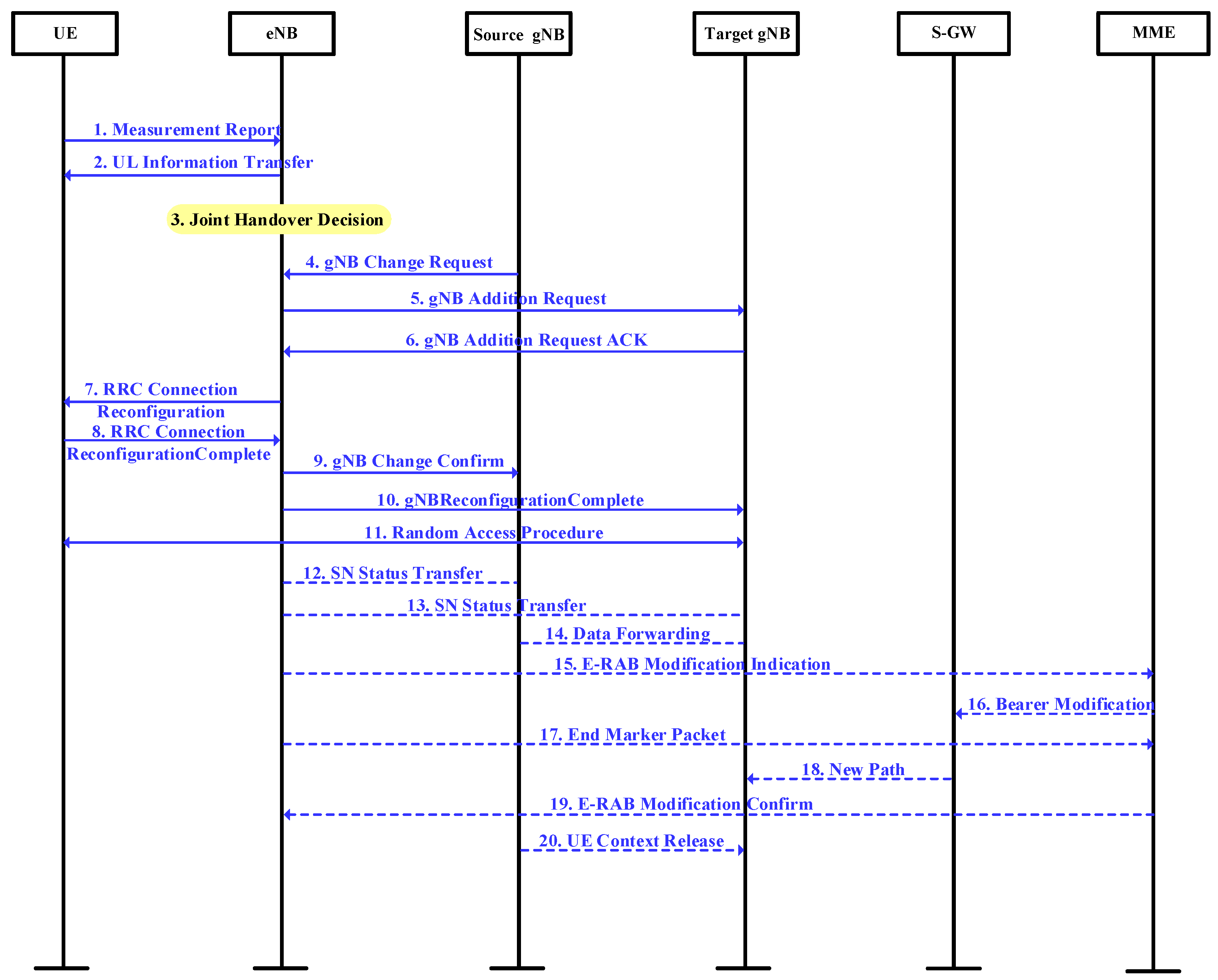
2.3. Handover Signaling

In the 5G NSA scenario, there are various types of handover according to different base stations and carrier frequencies. This section focuses on the scenario whereby the LTE cell in which the UE is located remains unchanged, while the 5G NR cell changes. The signaling flow chart is shown in Figure 2. In Figure 2, eNB represents the macro base station in the 5G heterogeneous network, and source gNB represents the base station connected with UE before handover. Target gNB represents the new base station connected with the UE after handover. SGW represents Serving Gateway, whose functions include mobility support, downlink packet caching, data transmission, and packet routing. Mobility Management Entity (MME) supports air interface security authentication, SGW selection, and mobility management.
In the signaling process described in Figure 2:
  • Items 1–2 mean that the UE uploads measurement reports according to the periodic configuration; the source gNB selects the target gNB after receiving the A3 event measurement report.
  • Items 3–4 mean that after the joint decision, the source gNB triggers a gNB change process by sending the gNB "Change Required" message to the eNB.
  • Items 5–6 mean that the eNB sends a gNB “Addition Request” message to the target gNB and requests for UE resources allocation.
  • Item 7 means that the eNB sends the UE RRC a "Connection Reconfiguration" message.
  • Item 8 means that the UE receives the RRC "Reconfiguration" message and completes the reconfiguration, and then the eNB returns a "Connection Reconfiguration Complete" message to the RRC.
  • Item 9 means that if the target gNB successfully allocates the resources, it will send the gNB "Change Confirm" message to the source gNB.
  • Item 10 means that the RRC reconfiguration is complete and the eNB confirms the reconfiguration is complete by sending the target gNB a gNB "Reconfiguration Complete" message.
  • Item 11 means that the UE starts the random access process.
  • Items 12–13 mean that for the scenarios where the bearing type changes, in order to reduce the current outages, data forwarding is need between gNBs.
  • Item 14 means that the gNB reports the NR flow to the eNB.
  • Items 15–19 mean that the user plane path between gNB and EPC is updated.
  • Item 20 means that the source gNB received the UE "Context Release" message, then releases the UE context.
The algorithm for the joint handover decision scheme is shown in Figure 3. Firstly, the speed and position parameters of the UE are obtained according to the results of the handover measurement, and the RSRP handover trigger threshold is calculated. Secondly, determine whether the signal received by the UE from the target gNB and the source gNB meets the RSRP handover condition. If the decision condition is satisfied, the handover will be triggered. If the decision condition is not met, the RSRQ threshold calculated by related parameters is used to determine whether the current communication condition meets the RSRQ handover condition. If the decision conditions are met, the handover will be triggered; if not, the handover measurement stage will be returned, and the UE will continue to report the measurement periodically.

3. Performance Analysis

3.1. Traditional Handover Scheme

When the UE is at a certain position x, the distance between gNB a and gNB b can be expressed as:
d a = x 2 + h g h m 2 d b = d a b x 2 + h f h m 2 d a 1 = d i + x 2 + h g h m 2 d a 2 = d i x 2 + h g h m 2 d b 1 = d i d a b + x 2 + h g h m 2 d b 2 = d i + d a b x 2 + h g h m 2 ,
where h m and h g are the heights of the UE and gNB antenna, respectively. Assuming that there are two adjacent gNBs with the same frequency on both sides of each gNB, and the distance between the two gNBs with the same frequency is d i , then the two gNBs with the same frequency as gNB a can be expressed as gNB a 1 and gNB a 2 , and the two gNBs with the same frequency as gNB b can be expressed as gNB b 1 and gNB b 2 . At this time, the signal strength received by the UE from each gNB can be expressed as:
P r m , x = P t P L m , d m ε 0 , σ m , m gNB C ,
where gNB C is the set of gNB, ε 0 , σ m is the shadow fading, and ε 0 , σ m is a Gaussian distribution variable with 0 mean and standard deviation σ m . P L m , d m is the path propagation loss of signal from gNB m to the UE, and the calculation formula can be expressed as:
P a t h s = + 10 β log 10 d m .
When the 28 GHz carrier signal is an LOS, = 61.4 and β = 2. When the carrier signal is a NLOS (non-line of sight) scene, = 72.0 and β = 2.92 [45]. Actually, a gNB may have multiple interfering base stations, but due to the rapid attenuation of millimeter-wave signals, the interference magnitude of distant base stations is quite slight. In order to simplify the model and facilitate the calculation, we configure two same-frequency-interference base stations for each gNB. When the UE is at a certain position x, the interference signal strength received from gNB a and gNB b with the same frequency can be expressed as:
I a , x dBm = 10 log 10 10 P r a 1 , x P r a 1 , x 10 10 + 10 P r a 2 , x P r a 2 , x 10 10 , I b , x dBm = 10 log 10 10 P r b 1 , x P r b 1 , x 10 10 + 10 P r b 2 , x P r b 2 , x 10 10 .
Then, the received signal quality of the UE at this position can be further calculated as:
S I R a , x dB = P r a , x dBm I a , x dBm , S I R b , x dB = P r b , x dBm I b , x dBm .
According to the traditional handover decision algorithm, the handover trigger probability is:
P x h a n d o v e r = P P r b , x P r a , x Γ + P P r b , x P r a , x < Γ × P S I R b , x S I R a , x Γ .
In the above expression, the probability of satisfying the RSRP handover threshold can be expressed as Equation (12):
P P r b , x P r a , x Γ = P P L b , d b + P L a , d a ε 0 , σ b + ε 0 , σ a Γ = P ε 0 , σ a Γ + P L b , d b P L a , d a + ε 0 , σ b = P ε 0 , σ a Γ + P L b , d b P L a , d a + ε 0 | ε 0 , σ b = ε 0 × P ε 0 , σ b = ε 0 = 1 2 π σ b 2 Q Γ + P L b , d b P L a , d a + ε 0 σ a exp ε 0 2 2 σ b 2 d ε 0 .
In Equation (12), Q x is a random variable with standard normal distribution, and the probability that its value is greater than x is expressed as:
Q x = 1 2 π x exp t 2 2 d t .
The probability that the RSRP handover threshold is not met can be expressed as:
P P r b , x P r a , x < Γ = 1 2 π σ b 2 1 Q Γ + P L b , d b P L a , d a + ε 0 σ a exp ε 0 2 2 σ b 2 d ε 0 .
In summary, it can be concluded that in the traditional handover scheme, the handover trigger probability between two gNBs is shown as Equation (15):
P S I R b , x S I R a , x Γ = 1 2 π σ b 2 Q Γ + P L b , d b P L a , d a + I ( b , x ) I a , x + ε 0 σ a exp ε 0 2 2 σ b 2 d ε 0 .
In this section, we define that if the SIR of the signal received by the UE from gNB is smaller than a threshold Υ dB, the link will be interrupted. Therefore, the probability of link interruption between the UE and gNB a can be expressed as:
P a , x o u t = P S I R a , x < Υ = P P r a , x I a , x < Υ = P P t P L a , d a ε 0 , σ a I a , x < Υ = P ε 0 , σ a > P t P L a , d a I a , x Υ = Q P t P L a , d a I a , x Υ σ a .
Similarly, the probability of link interruption between the UE and gNB b can be expressed as:
P b , x o u t = Q P t P L b , d b I b , x Υ σ b .
In the traditional handover scheme, the handover success probability is the probability meeting the following conditions: first, the communication link is not interrupted before the handover is triggered; second, the handover is triggered and completed at the appropriate position; and finally, the communication link is not interrupted after the handover is complete. Therefore, the handover success probability between two gNBs can be expressed as:
P ( x ) s u c c e s s = i = 0 x 1 P a , i o u t × P ( x ) h a n d o v e r × i = x d a b 1 P b , i o u t .

3.2. Beam-Based Enhanced Handover Scheme

As for the handover scheme proposed in this paper, when the UE is in the overlapping region of two gNBs, the beam gain can be adjusted and the received signal strength of the UE from gNB a can be obtained, which is expressed as:
P r a , x B F = P t P L a , d a ε 0 , σ a , x d a b r , 0.5 d a b P t P L a , d a + G 2 G 1 ε 0 , σ a , x 0.5 d a b , r .
The signal strength received by the UE from gNB a will vary according to its position in the overlapping region due to the adjustment of the gNB a beam gain. Similarly, the received signal strength of the UE from gNB b can be expressed as:
P r b , x B F = P t P L b , d b + G 2 ε 0 , σ b , x d a b r , r .
It is known that beamforming technology can effectively reduce the interference of adjacent co-frequency gNB, so the interference elimination factor is set here. Then, the interference strength received by the UE from the adjacent co-frequency gNB can be expressed as:
I a , x B F = 10 log 10 β 10 P r a 1 , x P r a 1 , x 10 10 + 10 P r a 2 , x P r a 2 , x 10 10 , I b , x B F = 10 log 10 β 10 P r b 1 , x P r b 1 , x 10 10 + 10 P r b 2 , x P r b 2 , x 10 10 .
Then, the quality of signals received by the UE from gNB a and gNB b can be expressed as:
S I R a , x B F dB = P r a , x B F dBm I a , x B F dBm , S I R b , x B F dB = P r b , x B F dBm I b , x B F dBm .
Then, the handover trigger probability of the proposed scheme is:
P x B F _ h o = P P r b , x B F P r a , x B F Γ r s r p ( x ) + P P r b , x B F P r a , x B F < Γ r s r p ( x ) × P S I R b , x B F S I R a , x B F Γ r s r q ( x ) .
Further, when the UE is in the overlapping area and on the left side of the center line, the handover trigger probability can be expressed as Equation (24):
P x B F _ h o = 1 2 π σ b 2 Q Γ r s r p + P L b , d b P L a , d a G 2 + ε 0 σ a exp ε 0 2 2 σ b 2 d ε 0 + 1 2 π σ b 2 1 Q Γ r s r p + P L b , d b P L a , d a G 2 + ε 0 σ a exp ε 0 2 2 σ b 2 d ε 0 × 1 2 π σ b 2 Q Γ r s r q + P L b , d b P L a , d a + I ( b , x ) B F I a , x B F G 2 + ε 0 σ a exp ε 0 2 2 σ b 2 d ε 0 .
Similar to the traditional handover scheme, the probability of the link interruption between gNB a and the UE in the handover process is:
P a , x B F _ o u t = Q P t P L a , d a I a , x Υ σ a , x d a b r , 0.5 d a b Q P t P L a , d a I a , x Υ + G 2 G 1 σ a , x 0.5 d a b , r .
The probability of interruption of the link between gNB b and the UE is:
P b , x B F _ o u t = Q P t P L b , x I b , x Υ + G 2 σ b , x d a b r , r .
In summary, the probability of the success of the handover scheme proposed in this section is shown as follows:
P ( x ) B F _ s u c c e s s = i = 0 x 1 P a , i B F _ o u t × P ( x ) B F _ h o × i = x d a b 1 P b , i B F _ o u t .

4. Simulation Result and Discussion

Based on the analysis in previous sections, this section uses the MATLAB platform to simulate and verify the proposed beam-based enhanced handover scheme based on adaptive threshold. Specific simulation parameters are shown in the Table 2. According to the parameters, the modeling was conducted to simulate the movement of UE between two gNBs and the handover procedure through MATLAB. The speed and shadow fading parameters were configured according to Table 2. Then, the UE movement process was simulated, and the changes of RSRP and RSRQ were recorded, as well as the changes of handover outage probability and success probability.
Figure 4 and Figure 5, respectively, present the RSRP received from gNB a, gNB b, and the quality of the received signal when the UE is in different positions. The curve of the gNB a signal is represented by asterisks, and the curve of gNB b is represented by circles. As can be seen from the figures, as the UE moves toward gNB b, the signal strength and signal quality received by the UE from the original gNB a base station gradually decrease, while the signal strength and signal quality received from the target gNB b base station gradually increase. Near the intersection of the two curves is the overlapping area of the two base stations, which is where the handover will take place. Furthermore, due to the superposition of different beam forming gains, the RSRP of gNB b signals received by the UE increases at 180 m, and the gNB a signals received by the UE decrease at 240 m. Therefore, through the beamforming scheme, the strength and quality of the received signal at the edge of the cell can be significantly improved, and the difference between the signal strength of the target gNB and the source gNB can also be increased to help trigger the handover.
Figure 6 shows the relation of RSRQ threshold at different speeds. We selected three common speeds in the coverage of gNB for simulation, 5 m/s, 10 m/s, and 15 m/s. For UE which is too fast, we recommend a lower handover threshold for fast handover, or a direct connection to eNB to reduce handover frequency. As shown in the figure, with a faster UE speed, the smaller RSRQ threshold is configured for the UE. In this way, the fast handover will be triggered and the stability of the UE link will be ensured. With the change of beamforming gain configuration, the RSRQ threshold will jump at 240 m, and the RSRQ threshold will adaptively decrease as the received signal of the target gNB becomes stronger. In addition, as the UE approaches the target gNB, the RSRQ trigger threshold gradually decreases to a fixed value. This is because the handover scheme proposed in this section has configured the minimum handover triggering threshold in the RSRQ adaptive algorithm, so as to reduce the probability of handover failure.
Figure 7 presents the handover trigger probability at different positions of UE with different speeds. As can be seen from the figure, the beam-based enhanced handover scheme based on adaptive threshold has a better performance of handover triggering probability than the traditional scheme. When the UE reaches the middle point of the overlapping area, the handover trigger probability of the traditional handover scheme is 34.7% (v = 10 m/s), while the handover trigger probability of the scheme proposed in this paper is 66.0%, which is a significant improvement. At the same time, since the scheme proposed in this section has configured different handover thresholds for UE with different speeds, the UE with high speed can trigger handover faster and complete the handover to the target gNB. Therefore, the handover scheme proposed in this section can be well applied in 5G NSA HetNets to improve the handover trigger probability between two gNBs.
Figure 8 elaborates the handover success probability with the UE in different speeds. As shown in the figure, at the edge of gNB a, the handover success probability of the scheme proposed in this section is nearly 27.4% higher than that of the traditional scheme. This is because the scheme proposed in this paper is configured with beamforming gain and adaptive handover threshold for UE in the overlapping area of two gNBs. Through the joint decision of RSRP and RSRQ, handover can be accurately triggered and the probability of link interruption during handover execution can be reduced. At the same time, because UE with different speeds are configured with adaptive trigger thresholds for handover, the handover can be triggered more quickly and accurately, and the UE with higner speeds have enough time to complete the handover.
The results obtained in this paper are similar to those in [33], which are aimed at the handover problem of millimeter-wave scenario and make use of the characteristics of millimeter-wave beamforming. Both studies refer to the signaling process of hard handover in the 5G NR standard, and introduce the operation of the beam to increase the handover performance. The method in the literature refered to the soft handover scheme in the previous version of a mobile communication system, and applied it to the millimeter-wave beam scenario. The authors of [46] proposed a seamless handover scheme based on location information in ultra-dense network scenarios, which used MIMO and multicast mechanisms to achieve seamless handover. Similar to our paper, they also used beamforming techniques to reduce signal interference. The handover principle of the dual-broadcast mechanism is similar to that of soft handover, where the mobile terminal will maintain the links with the two base stations completing the handover process. However, due to the shortcomings of soft handover, 3GPP chooses hard handover as the fundamental scheme in the 4G (LTE) and 5G (NR) networks. The scheme proposed in our paper is more suitable for seamless integrating into the existing 5G NR standards. For ultra-dense networks, a handover strategy based on multi-attribute decision was proposed in [47] to dynamically adjust and optimize handover parameters. The preselection of the target base station was based on the multi-attribute decision-making algorithm, which takes into account the RSRP, SINR, and the load of the candidate base station. The authors of [48] also provides a similar idea, using the user angle of movement, time to stay, and SINR to form the handover decision matrix. The handover strategy based on a multi-attribute decision-making algorithm can indeed make better decisions for handover. However, the multi-attribute decision-making algorithm will increase the burden of base stations or UE and greatly increase the cost of network operation. The method proposed in our paper can be integrated into the current 5G standard, improving the user experience without significantly increasing the network operation cost of operators. The authors of [30] also pays attention to the handover problem in 5G HetNets. By introducing a handover assistant micro base station between two macro bases, the seamless handover, including the inter-micro base stations’ handover between two macro bases, can be achieved. As for the scenario in this paper, we have also considered the improvement like the reference, adding an anchor node as an assistant node among gNBs. However, an eNB can have multiple gNBs, and the deployment of assistant nodes will greatly increase the cost of network deployment. The handover scheme in our paper does not need to add network entities, but only needs to improve the application of beamforming technology according to the measurement parameters reported by the UE, so that the signal of edge user can be enhanced and the handover performance can be improved.

5. Conclusions

Considering the HetNets scenario of 5G NSA, this paper proposes a millimeter-wave beamforming gain configuration scheme for the handover between two gNBs. By configuring different beamforming gains for the UE in the overlapping area, it improves the signal strength received by the UE at the edge of gNB, inhibits the interference of the same frequency gNB, and provides the basis for accurate handover decision. At the same time, aiming at resolving the difficulty of handover caused by the reduction in gNB coverage area, this paper proposes a joint handover decision algorithm based on adaptive threshold. For mobile terminals with different moving speeds, the corresponding RSRP trigger threshold and RSRQ trigger threshold are configured for them, so as to improve the performance of handover between gNBs. The final simulation results show that the beamforming gain scheme can effectively improve the signal strength at the edge of the gNB coverage area, and the joint handover decision algorithm based on speed adaptive can also effectively improve the handover trigger probability and handover success probability of the UE, which can better adapt to the 5G NSA HetNets scenario.
This paper improves the handover process in 5G HetNets, which can be submitted to 3GPP as a proposal, and is expected to provide a reference for the further evolution of 5G HetNets. For operators and equipment manufacturers, the scheme in this paper can be referred to during network deployment to increase the beamforming application function of gNB equipment, enhance the signal strength at the edge of gNB coverage, increase the handover success rate, and improve the user experience. However, the method proposed in this paper increases the content of UE signal measurement and a small amount of signaling interaction, which may increase the system burden when there are a large number of mobile terminals. At the same time, the environmental interference considered in this paper is relatively simple, while in actual scenarios, complex scenarios such as LOS, NLOS, and indoor/outdoor handover may exist. Therefore, as for future research, we plan to improve the method in various scenarios with the coexistence of LOS/NLOS and multipath fading. Furthermore, we will continue to study the adaptive configuration of handover parameters for mobile terminals with variable speeds, as well as the high-reliability and low-latency handover scheme of multiple terminals.

Author Contributions

Conceptualization, Z.Z.; methodology, Z.Z., Z.J. and B.Y.; software, Z.Z. and Z.J.; validation, Z.Z. and B.Y.; formal analysis, Z.Z.; investigation, Z.Z. and Z.J.; resources, B.Y. and X.S.; data curation, Z.Z. and Z.J.; writing—original draft preparation, Z.Z. writing—review and editing, Z.J., B.Y. and X.S.; visualization, Z.Z. and Z.J.; supervision, X.S.; project administration, B.Y.; funding acquisition, X.S. All authors have read and agreed to the published version of the manuscript.

Funding

This research was funded by the National Key Research and Development Program under Grant 2020YFB1807100.

Data Availability Statement

Not applicable.

Conflicts of Interest

The authors declare no conflict of interest.

References

  1. Andrewsand, J.G.; Buzzi, S.; Choi, W.; Hanly, S.V.; Lozano, A.; Soong, A.C.K.; Zhang, J.C. What will 5G be? IEEE J. Sel. Areas Commun. 2014, 32, 1065–1082. [Google Scholar] [CrossRef]
  2. Dong, Y.; Chen, Z.; Fan, P.; Letaief, K.B. Mobility-Aware Uplink Interference Model for 5G Heterogeneous Networks. IEEE Trans. Wirel. Commun. 2015, 15, 1065–1082. [Google Scholar] [CrossRef]
  3. Jo, Y.; Kim, H.; Lim, J.; Hong, D. Self-Optimization of Coverage and System Throughput in 5G Heterogeneous Ultra-Dense Networks. IEEE Wirel. Commun. Lett. 2020, 9, 285–288. [Google Scholar] [CrossRef]
  4. Ji, B.; Chen, Z.; Mumtaz, S.; Han, C.; Li, C.; Wen, H.; Wang, D. A vision of IoV in 5G HetNets: Architecture, key technologies, applications, challenges, and trends. IEEE Netw. 2022, 36, 153–161. [Google Scholar] [CrossRef]
  5. Zhao, J.; Ni, S.; Yang, L.; Zhang, Z.; Gong, Y.; You, X. Multiband cooperation for 5G HetNets: A promising network paradigm. IEEE Veh. Technol. Mag. 2019, 14, 153–161. [Google Scholar] [CrossRef]
  6. Zhang, H.; Huang, W.; Liu, Y. Handover Probability Analysis of Anchor-Based Multi-Connectivity in 5G User-Centric Network. IEEE Wirel. Commun. Lett. 2019, 8, 396–399. [Google Scholar] [CrossRef]
  7. Agarwal, B.; Togou, M.A.; Ruffini, M.; Muntean, G.M. A Comprehensive Survey on Radio Resource Management in 5G HetNets: Current Solutions, Future Trends and Open Issues. IEEE Commun. Surv. Tutorials 2022, 24, 2495–2534. [Google Scholar] [CrossRef]
  8. Lee, C.; Jung, J.; Chung, J.M. Intelligent Dual Active Protocol Stack Handover Based on Double DQN Deep Reinforcement Learning for 5G mmWave Networks. IEEE Trans. Veh. Technol. 2022, 71, 7572–7584. [Google Scholar] [CrossRef]
  9. Alraih, B.S.; Nordin, R.; Abu-Samah, A.; Shayea, I.; Abdullah, N.F. A Survey on Handover Optimization in Beyond 5G Mobile Networks: Challenges and Solutions. IEEE Access 2023, 11, 59317–59345. [Google Scholar] [CrossRef]
  10. Hong, S.; Brand, J.; Choi, J.I.; Jain, M.; Mehlman, J.; Katti, S.; Levis, P. Applications of self-interference cancellation in 5G and beyond. IEEE Commun. Mag. 2014, 52, 114–121. [Google Scholar] [CrossRef]
  11. Li, Y.; Zhao, Z.; Tang, Z.; Yin, Y. Differentially Fed, Dual-Band Dual-Polarized Filtering Antenna with High Selectivity for 5G Sub-6 GHz Base Station Applications. IEEE Trans. Antennas Propag. 2020, 68, 3231–3236. [Google Scholar] [CrossRef]
  12. Wang, P.; Li, Y.; Song, L.; Vucetic, B. Multi-gigabit millimeter wave wireless communications for 5G: From fixed access to cellular networks. IEEE Commun. Mag. 2015, 53, 168–178. [Google Scholar] [CrossRef]
  13. Yang, X.; Matthaiou, M.; Yang, J.; Wen, C.K.; Gao, F.; Jin, S. Hardware-Constrained Millimeter-Wave Systems for 5G: Challenges, Opportunities, and Solutions. IEEE Commun. Mag. 2019, 57, 44–50. [Google Scholar] [CrossRef]
  14. Ghafoor, K.Z.; Kong, L.; Zeadally, S.; Sadiq, A.S.; Epiphaniou, G.; Hammoudeh, M.; Bashir, A.K.; Mumtaz, S. Millimeter-wave communication for internet of vehicles: Status, challenges, and perspectives. IEEE Internet Things J. 2020, 7, 8525–8546. [Google Scholar] [CrossRef]
  15. He, R.; Schneider, C.; Ai, B.; Wang, G.; Zhong, Z.; Dupleich, D.A.; Thomae, R.S.; Boban, M.; Luo, J.; Zhang, Y. Propagation channels of 5G millimeter-wave vehicle-to-vehicle communications: Recent advances and future challenges. IEEE Veh. Technol. Mag. 2019, 15, 16–26. [Google Scholar] [CrossRef]
  16. Zhang, D.; Li, A.; Shirvanimoghaddam, M.; Cheng, P.; Li, Y.; Vucetic, B. Codebook-based training beam sequence design for millimeter-wave tracking systems. IEEE Trans. Wirel. Commun. 2019, 18, 5333–5349. [Google Scholar] [CrossRef]
  17. Yue, G.; Yu, D.; Cheng, L.; Lv, Q.; Luo, Z.; Li, Q.; Luo, J.; He, X. Millimeter-Wave System for High-Speed Train Communications Between Train and Trackside: System Design and Channel Measurements. IEEE Trans. Veh. Technol. 2019, 68, 11746–11761. [Google Scholar] [CrossRef]
  18. Sarker, M.A.L.; Orikumhi, I.; Han, D.S.; Kim, S. Blockwise Phase Rotation-Aided Analog Transmit Beamforming for 5G mmWave Systems. IEEE Wirel. Commun. Lett. 2021, 10, 2365–2368. [Google Scholar] [CrossRef]
  19. Wang, W.; Cheng, N.; Liu, Y.; Zhou, H.; Lin, X.; Shen, X. Content delivery analysis in cellular networks with aerial caching and mmWAVE backhaul. IEEE Trans. Veh. Technol. 2021, 70, 4809–4822. [Google Scholar] [CrossRef]
  20. Bai, L.; Huang, Z.; Zhang, X.; Cheng, X. A non-stationary 3D model for 6G massive MIMO mmWave UAV channels. IEEE Trans. Wirel. Commun. 2022, 21, 4325–4339. [Google Scholar] [CrossRef]
  21. Yan, L.; Fang, X.; Fang, Y. A novel network architecture for C/U-plane staggered handover in 5G decoupled heterogeneous railway wireless systems. IEEE Trans. Intell. Transp. Syst. 2017, 18, 3350–3362. [Google Scholar] [CrossRef]
  22. Khosravi, S.; Shokri-Ghadikolaei, H.; Petrova, M. Learning-based handover in mobile millimeter-wave networks. IEEE Trans. Cogn. Commun. Netw. 2020, 7, 663–674. [Google Scholar] [CrossRef]
  23. Jasim, M.A.; Siasi, N.; Ghani, N. Soft Self-Handover Scheme for mmWave Communications. In Proceedings of the 2019 SoutheastCon, Huntsville, AL, USA, 11–14 April 2019; pp. 1–6. [Google Scholar]
  24. Ozmat, U.; Demirkol, M.F.; Yazici, M.A. Learning-based handover in mobile millimeter-wave networks. In Proceedings of the 2020 IEEE 25th International Workshop on Computer Aided Modeling and Design of Communication Links and Networks (CAMAD), Pisa, Italy, 14–16 September 2020; pp. 1–6. [Google Scholar]
  25. Tran, H.Q.; Van Phan, C.; Vien, Q.T. An Overview of 5G Technologies. In Emerging Wireless Communication and Network Technologies; Springer: Singapore, 2018; pp. 59–80. [Google Scholar]
  26. Kutty, S.; Sen, D. Beamforming for millimeter wave communications: An inclusive survey. IEEE Commun. Surv. Tutorials 2015, 18, 949–973. [Google Scholar] [CrossRef]
  27. Giordani, M.; Polese, M.; Roy, A.; Castor, D.; Zorzi, M. A Tutorial on Beam Management for 3GPP NR at mmWave Frequencies. IEEE Commun. Surv. Tutorials 2018, 21, 173–196. [Google Scholar] [CrossRef]
  28. Bai, L.; Li, T.; Yu, Q.; Choi, J.; Zhang, W. Cooperative Multiuser Beamforming in mmWave Distributed Antenna Systems. IEEE Trans. Veh. Technol. 2018, 67, 12394–12397. [Google Scholar] [CrossRef]
  29. 3GPP TS 38.331 V16.9.0. NR: Radio Resource Control (RRC) Protocol Specification. 2022. 06. Available online: https://www.3gpp.org/ftp/Specs/archive/38_series/38.331/38331-g90.zip (accessed on 1 October 2023).
  30. Zhang, Z.; Zhao, J.; Ni, S.; Gong, Y. A seamless handover scheme with assisted eNB for 5G C/U plane split heterogeneous network. IEEE Access 2019, 7, 164256–164264. [Google Scholar] [CrossRef]
  31. Nguyen, K.N.; Ali, A.; Mo, J.; Ng, B.L.; Va, V.; Zhang, J.C. Beam Management with Orientation and RSRP using Deep Learning for Beyond 5G Systems. In Proceedings of the 2022 IEEE International Conference on Communications Workshops (ICC Workshops), Seoul, Republic of Korea, 16–20 May 2022; pp. 133–138. [Google Scholar]
  32. Bai, T.; Cezannec, J.; Wang, H.; Raghavan, V.; Koymen, O.H.; Li, J. Analysis of RSRP Prediction in Millimeter Wave Systems. In Proceedings of the 2019 53rd Asilomar Conference on Signals, Systems, and Computers, Pacific Grove, CA, USA, 3–6 November 2019; pp. 789–793. [Google Scholar]
  33. Liu, Z.; Zhou, E.; Cui, J.; Dong, Z.; Fan, P. A Double-Beam Soft Handover Scheme and Its Performance Analysis for mmWave UAV Communications in Windy Scenarios. IEEE Trans. Veh. Technol. 2023, 72, 893–906. [Google Scholar] [CrossRef]
  34. Luo, W.; Fang, X.; Cheng, M.; Zhou, X. An optimized handover trigger scheme in LTE systems for high-speed railway. In Proceedings of the Fifth International Workshop on Signal Design and Its Applications in Communications, Guilin, China, 10–14 October 2011; pp. 193–196. [Google Scholar]
  35. Alkhateeb, A.; Beltagy, I.; Alex, S. Machine Learning for Reliable mmWave System: Blockage Prediction And Proactive Handoff. In Proceedings of the 2018 IEEE Global Conference on Signal and Information Processing (GlobalSIP), Anaheim, CA, USA, 26–29 November 2018; pp. 1055–1059. [Google Scholar]
  36. Kustiawan, I.; Chi, K.H. Handoff decision using a Kalman filter and fuzzy logic in heterogeneous wireless networks. IEEE Commun. Lett. 2015, 19, 2258–2261. [Google Scholar] [CrossRef]
  37. Al Achhab, T.; Abboud, F.; Assalem, A. A Robust Self-Optimization Algorithm Based on Idiosyncratic Adaptation of Handover Parameters for Mobility Management in LTE-A Heterogeneous Networks. IEEE Access 2021, 9, 154237–154264. [Google Scholar] [CrossRef]
  38. He, H.; Li, X.; Feng, Z.; Hao, J.; Wang, X.; Zhang, H. An adaptive handover trigger strategy for 5G C/U plane split heterogeneous network. In Proceedings of the 2017 IEEE 14th International Conference on Mobile Ad Hoc and Sensor Systems (MASS), Orlando, FL, USA, 22–25 October 2017; pp. 476–480. [Google Scholar]
  39. Wu, X.; O’Brien, D.C.; Deng, X.; Linnartz, J.P.M.G. Smart handover for hybrid LiFi and WiFi networks. IEEE Trans. Wirel. Commun. 2020, 19, 8211–8219. [Google Scholar] [CrossRef]
  40. Banna, R.; ELAttar, H.; Abou El-Dahab, M.M. Fast Adaptive Handover using Fuzzy Logic for 5G Communications on High Speed Trains. In Proceedings of the 2021 16th International Conference on Telecommunications (ConTEL), Zagreb, Croatia, 30 June–2 July 2021; pp. 10–17. [Google Scholar]
  41. Silva, K.D.C.; Becvar, Z.; Frances, C.R.L. Adaptive hysteresis margin based on fuzzy logic for handover in mobile networks with dense small cells. IEEE Access 2018, 6, 17178–17189. [Google Scholar] [CrossRef]
  42. Shayea, I.; Ergen, M.; Azizan, A. Individualistic Dynamic Handover Parameter Self-Optimization Algorithm for 5G Networks Based on Automatic Weight Function. IEEE Access 2020, 8, 214392–214412. [Google Scholar] [CrossRef]
  43. Vasudeva, K.; Şimsek, M.; López-Pérez, D.; Güvenç, I. Impact of channel fading on mobility management in heterogeneous networks. In Proceedings of the 2015 IEEE International Conference on Communication Workshop (ICCW), London, UK, 8–12 June 2015; pp. 2206–2211. [Google Scholar]
  44. Zhu, H.; Peng, Y. Research on Adaptive Handover Scheme Based on Improved Genetic Algorithm. Procedia Comput. Sci. 2020, 166, 557–562. [Google Scholar] [CrossRef]
  45. Akdeniz, M.R.; Liu, Y.; Samimi, M.K.; Sun, S.; Rangan, S.; Rappaport, T.S.; Erkip, E. Millimeter Wave Channel Modeling and Cellular Capacity Evaluation. IEEE J. Sel. Areas Commun. 2014, 32, 1164–1179. [Google Scholar] [CrossRef]
  46. Chuang, M.C.; Chen, M.C. NASH: Navigation-Assisted Seamless Handover Scheme for Smart Car in Ultra dense Networks. IEEE Trans. Veh. Technol. 2018, 67, 1649–1659. [Google Scholar] [CrossRef]
  47. Huang, W.; Wu, M.; Yang, Z.; Sun, K.; Zhang, H.; Nallanathan, A. Self-Adapting Handover Parameters Optimization for SDN-Enabled UDN. IEEE Trans. Wirel. Commun. 2022, 21, 6434–6447. [Google Scholar] [CrossRef]
  48. Alhabo, M.; Zhang, L. Multi-Criteria Handover Using Modified Weighted TOPSIS Methods for Heterogeneous Networks. IEEE Access 2018, 6, 40547–40558. [Google Scholar] [CrossRef]
Figure 1. The beamforming-based enhanced handover scheme based on adaptive threshold.
Electronics 12 04131 g001
Figure 2. The signaling flow of the beamforming-based enhanced handover scheme based on adaptive threshold.
Electronics 12 04131 g002
Figure 3. The flow chart of handover decision scheme based on adaptive RSRP and RSRQ thresholds.
Electronics 12 04131 g003
Figure 4. The relationship between RSRP and the location of UE.
Electronics 12 04131 g004
Figure 5. The relationship between SINR and the location of UE.
Electronics 12 04131 g005
Figure 6. RSRQ threshold at different speeds.
Electronics 12 04131 g006
Figure 7. Handover trigger probability.
Electronics 12 04131 g007
Figure 8. Handover success probability.
Electronics 12 04131 g008
Table 1. Beamforming gains at different positions.
gNBUE LocationgNB Transmit PowerBeamforming Gain
a d a b r , 0.5 d a b P t G 1 G 1
a 0.5 d a b , r P t G 1 G 2
b 0.5 d a b , r P t G 2
Table 2. System parameters.
ParametersValues
Frequency of gNB, f c 1 28 GHz
Transmit power of gNB, P t s 23 dBm
Handover execute time, τ 0.5 s
gNB coverage radius, r300 m
Distance of two neighboring gNBs, d a b 480 m
Distance of two co-frequency gNBs, d i 1500 m
gNB antenna height, h g 10 m
UE antenna height, h m 1 m
Interference elimination factor, β 0.01
Traditional handover trigger threshold, Γ 3 dB
SIR threshold, Υ −35 dB
RSRQ max threshold, Γ h 20 dB
RSRQ min threshold, Γ l 3 dB
Highest channel quality, Δ h 40 dB
Lowest channel quality, Δ l 10 dB
Beamforming gain, G 1 5 dB
Beamforming gain, G 2 3 dB
Disclaimer/Publisher’s Note: The statements, opinions and data contained in all publications are solely those of the individual author(s) and contributor(s) and not of MDPI and/or the editor(s). MDPI and/or the editor(s) disclaim responsibility for any injury to people or property resulting from any ideas, methods, instructions or products referred to in the content.

