
A Waveform Design for MIMO Sensing on Two-Dimensional Arrays with Sparse Estimation


Abstract
:1. Introduction
- In the time domain for compressed optimization, compared to ideal orthogonal MIMO waveforms such as the Hadamard sequence and Alltop sequence as the initial waveform, this work will use a Hadamard-coded waveform as the initial waveform which is more suitable for millimeter wave radar;
- In the spatial domain for compressed optimization, unlike most previous studies that have considered one-dimensional linear arrays that can only estimate the azimuth information of the target, this paper extends the research to CS-based MIMO radar systems based on L-shaped arrays and redesigned waveform optimizations;
- In the computational power domain, due to the use of a two-dimensional array based MIMO radar scenarios in this article, sparse recovery belongs to the problem of high correlation and high-dimensional signals, and algorithms such as OMP will no longer be applicable. Therefore, in order to achieve higher resolution and accuracy, this article introduces the Sparse Bayesian Learning (SBL) algorithm for the sparse estimation of both azimuth and elevation angles.
2. Waveform Design for CS-Based MIMO Radar
2.1. Signal Model
2.2. Reconstruction Performance Analysis
2.3. Waveform Design
3. Waveform Optimization and CS Recovery Algorithms for MIMO Radar
3.1. Optimization Algorithm Based on Simulated Annealing
| Algorithm 1 Simulated Annealing Algorithm | |
| Input: the initial solution, i.e., initial waveform vector , the objective function . | |
| Output: the best solution, i.e., optimized waveform . | |
| : | Initialization. Initial temperature, cooling schedule, Markov chain length. |
| : | IGenerate a new neighboring solution by applying a small perturbation or modified-tion to the current solution, and calculate the objective function value . |
| : | Verify the constraint and new solution. |
| if meet the constraint | |
| if < | |
| accept the new solution | |
| else | |
| accept the new solution in terms of the Metropolis criterion | |
| else | |
| discard the new solution | |
| end | |
| : | Update the temperature according to the cooling schedule. The acceptance probability of worse solutions decreases gradually as the temperature decreases. |
| : | Check if the stopping criteria are met. If met, terminate the iteration process and return the best solution as the final output, otherwise, repeat steps 2 to 4. |
3.2. CS Recovery Algorithm Based on Sparse Bayesian Learning
| Algorithm 2 Sparse Bayesian Learning Algorithm | |
| Input: the observation vector , the sensing matrix . | |
| Output: the estimated angles of targets. | |
| : | Initialization. Initialize the sparse coefficient estimation vector randomly, representing the weights of received signals at different DOA angles. |
| : | Calculate the likelihood function of the current sparse coefficient vector. |
| : | Update the sparse coefficient vector by the Expectation-Maximization (EM) algorithm. |
| : Calculate the posterior distribution of DOA angles, given the observed data. | |
| : Maximize the MAP function to update the sparse coefficient vector. | |
| : | Check if the stopping criteria are met. If met, terminate the iteration process, otherwise, repeat steps 2 to 3. |
| : | DOA Estimation. Use the updated sparse coefficient vector to calculate the estimated angles of targets and return the result. |
4. Simulation
4.1. Simulation Configuration
4.2. Simulation Results
5. Discussion
6. Conclusions
Author Contributions
Funding
Institutional Review Board Statement
Informed Consent Statement
Data Availability Statement
Conflicts of Interest
Abbreviations
| ISAC | Integrated sensing and communications |
| MIMO | Multiple-input multiple-output |
| CS | Compressed sensing |
| RCS | Reflection coefficient |
| RIP | Restricted isometry property |
| CSM | Coherence of the sensing matrix |
| SCSM | The sum of the cross-correlation |
| PSD | Positive semidefinite |
| SA | Simulated annealing |
| SBL | Sparse Bayesian learning |
| MAP | Maximum a posteriori |
| DOA | Direction of arrival |
| CDMA | Code division multiple access |
| ASCM | Average normalized coherence coefficient |
References
- Liu, A.; Huang, Z.; Li, M.; Wan, Y.; Li, W.; Han, T.X.; Liu, C.; Du, R.; Tan, D.K.P.; Lu, J.; et al. A Survey on Fundamental Limits of Integrated Sensing and Communication. IEEE Commun. Surv. Tutorials 2022, 24, 994–1034. [Google Scholar] [CrossRef]
- Cui, Y.; Liu, F.; Jing, X.; Mu, J. Integrating Sensing and Communications for Ubiquitous IoT: Applications, Trends, and Challenges. IEEE Netw. 2021, 35, 158–167. [Google Scholar] [CrossRef]
- Cohen, D.; Eldar, Y.C. Sub-Nyquist Radar Systems: Temporal, Spectral, and Spatial Compression. IEEE Signal Process. Mag. 2018, 35, 35–58. [Google Scholar] [CrossRef]
- Liu, F.; Zheng, L.; Cui, Y.; Masouros, C.; Petropulu, A.P.; Griffiths, H.; Eldar, Y.C. Seventy Years of Radar and Communications: The road from separation to integration. IEEE Signal Process. Mag. 2023, 40, 106–121. [Google Scholar] [CrossRef]
- Candès, E.J. The restricted isometry property and its implications for compressed sensing. Comptes Rendus Math. 2008, 346, 589–592. [Google Scholar] [CrossRef]
- Chen, C.-Y.; Vaidyanathan, P.P. Compressed Sensing in MIMO Radar. In Proceedings of the 2008 42nd Asilomar Conference on Signals, Systems and Computers, Pacific Grove, CA, USA, 26–29 October 2008; pp. 41–44. [Google Scholar]
- Gogineni, S.; Nehorai, A. Target Estimation Using Sparse Modeling for Distributed MIMO Radar. IEEE Trans. Signal Process. 2011, 59, 5315–5325. [Google Scholar] [CrossRef]
- Gurbuz, A.C.; McClellan, J.H.; Scott, W.R. A Compressive Sensing Data Acquisition and Imaging Method for Stepped Frequency GPRs. IEEE Trans. Signal Process. 2009, 57, 2640–2650. [Google Scholar] [CrossRef]
- Yu, Y.; Petropulu, A.P.; Poor, H.V. CSSF MIMO RADAR: Low-Complexity Compressive Sensing Based MIMO Radar That Uses Step Frequency. arXiv 2011, arXiv:1101.2719. [Google Scholar]
- Yu, Y.; Sun, S.; Madan, R.N.; Petropulu, A. Power Allocation and Waveform Design for the Compressive Sensing Based MIMO Radar. IEEE Trans. Aerosp. Electron. Syst. 2014, 50, 898–909. [Google Scholar] [CrossRef]
- Chen, P.; Wu, L. Joint Design Transmission Waveform and Sensing Matrix for the Compressive Sensing Radar. In Proceedings of the 2014 9th International Symposium on Communication Systems, Networks & Digital Sign (CSNDSP), Manchester, UK, 23–25 July 2014; pp. 558–563. [Google Scholar]
- Rogers, C.A.; Popescu, D.C. Compressed Sensing MIMO Radar System for Extended Target Detection. IEEE Syst. J. 2021, 15, 1381–1389. [Google Scholar] [CrossRef]
- Ajorloo, A.; Amini, A.; Bastani, M.H. A Compressive Sensing-Based Colocated MIMO Radar Power Allocation and Waveform Design. IEEE Sensors J. 2018, 18, 9420–9429. [Google Scholar] [CrossRef]
- Gogineni, S.; Nehorai, A. Frequency-Hopping Code Design for MIMO Radar Estimation Using Sparse Modeling. IEEE Trans. Signal Process. 2012, 60, 3022–3035. [Google Scholar] [CrossRef]
- Daniel, A.; Popescu, D.C. MIMO Radar Waveform Design for Multiple Extended Targets Using Compressed Sensing. In Proceedings of the 2014 IEEE Radar Conference, Cincinnati, OH, USA, 19–23 May 2014; pp. 0567–0572. [Google Scholar]
- Daniel, A.; Popescu, D.C. Multiple Extended Target Detection Using MIMO Radar and Compressed Sensing. In Proceedings of the 2014 IEEE Military Communications Conference, Baltimore, MD, USA, 6–8 October 2014; pp. 777–782. [Google Scholar]
- Urkowitz, H. Filters for Detection of Small Radar Signals in Clutter. J. Appl. Phys. 2004, 24, 1024–1031. [Google Scholar] [CrossRef]
- Chen, S.; Donoho, D. Application of Basis Pursuit in Spectrum Estimation. In Proceedings of the 1998 IEEE International Conference on Acoustics, Speech and Signal Processing, ICASSP ’98 (Cat. No.98CH36181). Seattle, WA, USA, 15 May 1998; pp. 1865–1868. [Google Scholar]
- Cai, T.T.; Wang, L. Orthogonal Matching Pursuit for Sparse Signal Recovery With Noise. IEEE Trans. Inf. Theory 2011, 57, 4680–4688. [Google Scholar] [CrossRef]
- Tropp, J.A.; Gilbert, A.C. Signal Recovery from Random Measurements via Orthogonal Matching Pursuit. IEEE Trans. Inf. Theory 2007, 53, 4655–4666. [Google Scholar] [CrossRef]
- Needell, D.; Vershynin, R. Uniform Uncertainty Principle and Signal Recovery via Regularized Orthogonal Matching Pursuit. Found. Comput. Math. 2009, 9, 317–334. [Google Scholar] [CrossRef]
- Becker, S.; Bobin, J.; Candès, E.J. NESTA: A Fast and Accurate First-Order Method for Sparse Recovery. SIAM J. Imaging Sci. 2011, 4, 1–39. [Google Scholar] [CrossRef]
- Donoho, D.L.; Elad, M.; Temlyakov, V.N. Stable recovery of sparse overcomplete representations in the presence of noise. IEEE Trans. Inf. Theory 2005, 52, 6–18. [Google Scholar] [CrossRef]
- Kirpatrick, S.; Gelatt, C.D.; Vecchi, M.P. Optimization by simulated annealing. Readings Comput. Vis. 1987, 220, 606–615. [Google Scholar]
- Dai, J.; Bao, X.; Xu, W.; Chang, C. Root Sparse Bayesian Learning for Off-Grid DOA Estimation. IEEE Signal Process. Lett. 2017, 24, 46–50. [Google Scholar] [CrossRef]
- Groll, H.; Mecklenbrauker, C.; Gerstoft, P. Sparse Bayesian Learning for Directions of Arrival on an FPGA. In Proceedings of the 2018 IEEE Statistical Signal Processing Workshop (SSP), Freiburg im Breisgau, Germany,, 10–13 June 2018; pp. 623–627. [Google Scholar]
- Sun, H.; Brigui, F.; Lesturgie, M. Analysis and comparison of MIMO radar waveforms. In Proceedings of the 2014 International Radar Conference, Lille, France, 13–17 October 2014; pp. 1–6. [Google Scholar]


| Setting | Value |
|---|---|
| Antenna spacing | |
| Number of transmitting antennas | 8 |
| Number of pulses | 8 |
| Initial waveform | Hadamard-coded waveform |
| Reflection coefficients | complex Gaussian distribution |
| Number of targets | 3 |
| Angle grid | |
| Compression ratio | |
| Signal-to-noise ratio | |
| The number of runs per simulation | 2000 |
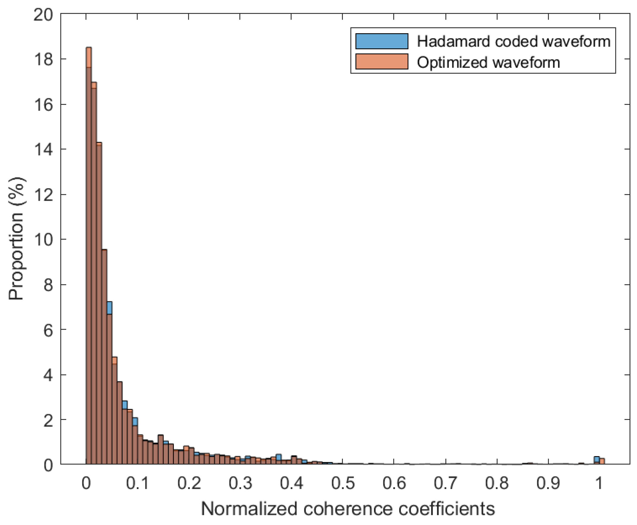
| ACSM/ | ACSM/ | ACSM/ | |
|---|---|---|---|
| Hadamard coded waveform | 0.1933 | 0.1795 | 0.1814 |
| Optimized waveform | 0.1836 | 0.1717 | 0.1755 |
Disclaimer/Publisher’s Note: The statements, opinions and data contained in all publications are solely those of the individual author(s) and contributor(s) and not of MDPI and/or the editor(s). MDPI and/or the editor(s) disclaim responsibility for any injury to people or property resulting from any ideas, methods, instructions or products referred to in the content. |
© 2023 by the authors. Licensee MDPI, Basel, Switzerland. This article is an open access article distributed under the terms and conditions of the Creative Commons Attribution (CC BY) license (https://creativecommons.org/licenses/by/4.0/).
Share and Cite
Liu, Y.; Pan, C.; Liu, X.; Zhu, Y.; Liu, Y. A Waveform Design for MIMO Sensing on Two-Dimensional Arrays with Sparse Estimation. Electronics 2023, 12, 3906. https://doi.org/10.3390/electronics12183906
Liu Y, Pan C, Liu X, Zhu Y, Liu Y. A Waveform Design for MIMO Sensing on Two-Dimensional Arrays with Sparse Estimation. Electronics. 2023; 12(18):3906. https://doi.org/10.3390/electronics12183906
Chicago/Turabian StyleLiu, Yiwen, Chong Pan, Xiaolong Liu, Ying Zhu, and Yifu Liu. 2023. "A Waveform Design for MIMO Sensing on Two-Dimensional Arrays with Sparse Estimation" Electronics 12, no. 18: 3906. https://doi.org/10.3390/electronics12183906
APA StyleLiu, Y., Pan, C., Liu, X., Zhu, Y., & Liu, Y. (2023). A Waveform Design for MIMO Sensing on Two-Dimensional Arrays with Sparse Estimation. Electronics, 12(18), 3906. https://doi.org/10.3390/electronics12183906