1. Introduction
Permanent magnet synchronous motors (PMSM) are applied in many areas, such as aerospace, industrial production and electric vehicles [
1,
2,
3]. Compared to other kinds of motors, PMSM have a high-torque density and power efficiency. In some special areas, the reliability of the drive system is very important, and the stable operation of the motor and its fault tolerant operation ability after faults have occurred require additional attention. Due to the requirements of a practical application, the fault tolerant control of PMSM has attracted much interest [
4,
5,
6].
Due to a series of reasons, such as excessive electromagnetic impact and physical connection failure, the motor system may experience open phase faults. According to [
7], open phase faults account for 38% among drive system faults. Once the open phase fault occurs, the output torque, efficiency and the reliability of drive system will be affected. In some more serious situations, the open phase fault will damage the drive system [
8,
9]. Hence, the fault-tolerant control is important for PMSM drive systems to cope with the open phase fault.
Usually, the Y connected PMSM driving structure is applied in many cases. This type of driving structure has the advantages of a simple structure. However, it has a weak fault tolerant ability when dealing with the open phase fault. The open winding topology provides more control degrees, and can be applied for the PMSM drive system with the open phase fault [
10,
11,
12,
13,
14]. In [
10], a novel fault-tolerant control strategy was proposed for the open winding drive system (OWDS) with open phase fault. The third harmonic flux linkage was taken into consideration to suppress the torque ripple after the open phase fault. In [
11], a fault tolerant predictive controller was designed for the OWDS with open phase fault. The proposed strategy can achieve effective control in pre-fault and post-fault conditions. In [
12], a novel strategy was proposed for the five-phase OWDS with open phase fault. The strategy develops a four-dimensional FOC transformation for the fault condition. In [
13], a fault tolerant strategy is firstly proposed for the OWDS with the second time open phase fault. The design idea is based on the bridge arm sharing. Besides the topology, the torque optimization strategy is designed to reduce the system torque ripple by injecting harmonic current. In [
14], an optimal strategy was proposed for the OWDS with open phase fault. In the strategy, the minimization of system copper loss and the maximization of system torque are the design objective. However, the open winding topology will bring some disadvantages, including expensive hardware cost and a high failure rate. Compared with the open winding topology, the PMSM drive system with four legs has fewer switching device requirements, and also has the merit of strong fault tolerant performance.
The PMSM drive system with four legs has attracted much attention [
15,
16,
17,
18,
19,
20,
21,
22,
23]. In [
15], a fault tolerant strategy is proposed for the three-phase four legs drive system with open phase fault. The strategy uses voltage compensation to compensate for the offset of the A-phase voltage to the dq axis voltage. In [
16], a feedforward element is designed to compensate the unbalance voltage, which result from the open phase fault in interior PMSM. In [
17], the resonant controller is designed applied to track the dq axis referenced current for the three-phase four legs drive system with open phase fault, and the voltage demand can be compensated adaptively by applying these control methods. In [
18], a new PMSM model was established based on the new reference frame transformation for fault tolerance. The proposed strategy can keep the current controller unchanged before and after fault, and the voltage feedforward does not need additional compensation. In [
19], a harmonic current injection strategy was applied in the fault tolerant method to suppress the harmonic torque. By injecting harmonic current into the phase current, the torque ripple can be suppressed. In [
20], the fault tolerant method was designed based on the principle of copper loss minimization. In the proposed method, d axis current is not zero and calculated based on the q axis current. In [
21], a common model predictive control strategy was applied in the healthy operation and fault operation. The suitability for different operations is verified by theoretical analysis. In [
22], a novel reference frame transformation including positive and inverse transformations was proposed for the fault tolerant of open phase fault. Then, a similar performance can be acquired under pre-fault and post-fault conditions. In [
23], a fault tolerant strategy was designed for the PMSM drive system, which modifies the control performance of the closed loop field weakening controller.
In this paper, a fault tolerant control method is proposed to further suppress the torque ripple. The proposed control method takes the third harmonic flux into consideration and the remaining phase voltages are determined based on the line voltages. The proposed method includes three parts: the torque-producing current calculator, phase voltage determination and voltage distributor. The torque-producing current calculator is designed by taking the third harmonic flux into consideration to calculate the torque-producing current. In the phase voltage determination, it was proved that the third harmonic flux has no influence on the line voltage equation. For healthy operation and fault operation, the voltage requirements in remaining healthy phases are determined based on the line voltages. Finally, two voltage distributors are designed to distribute the phase voltages into the remaining inverter leg.
The paper is organized as follows. In
Section 2, the studied drive system is introduced. In
Section 3, the proposed control method is presented, including torque-producing current calculator, phase voltage determination and voltage distributor. In
Section 4 and
Section 5, the proposed method is verified by simulation and experiment. Finally,
Section 6 concludes this paper.
2. The Studied Drive System
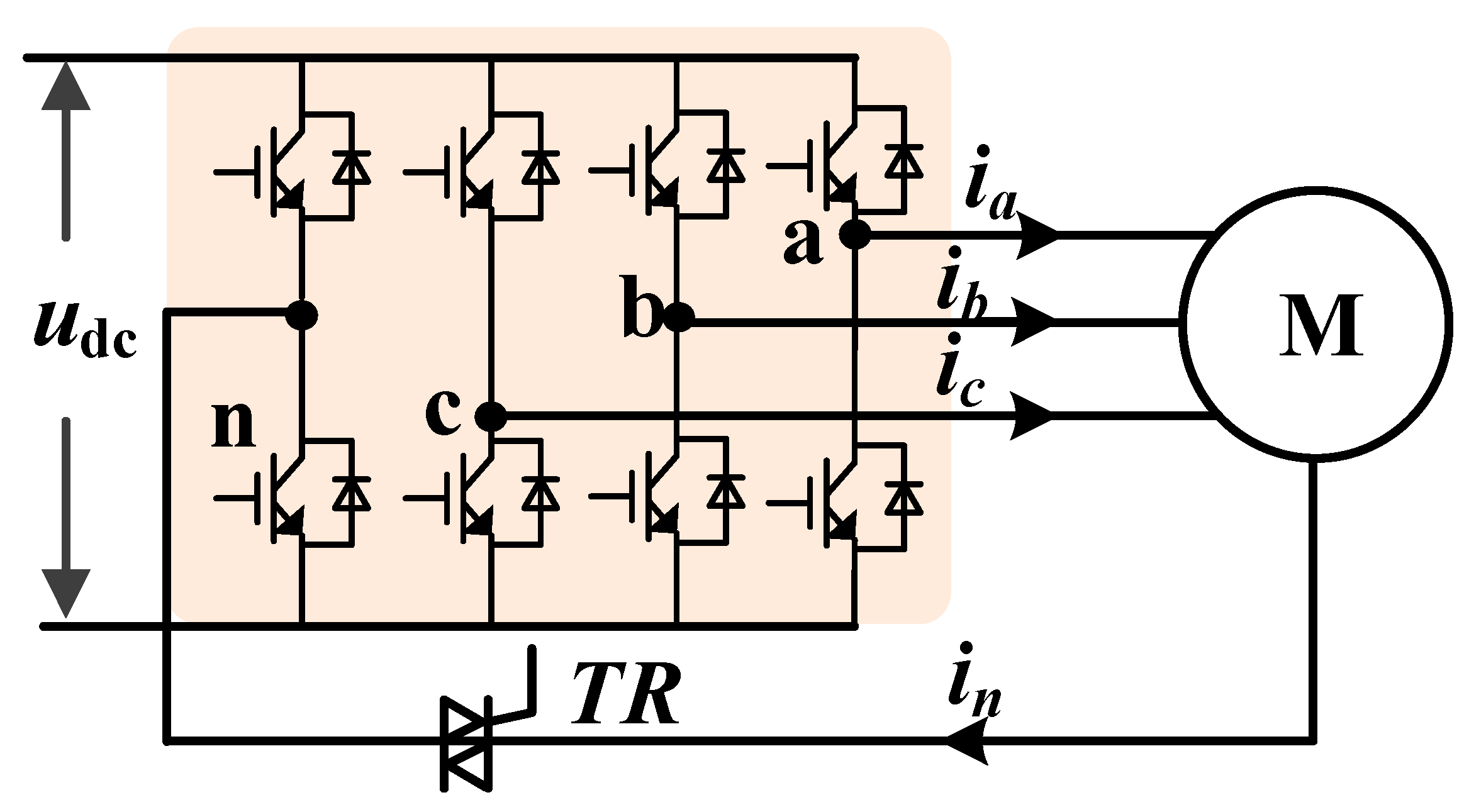
In this section, the studied drive system is introduced and the mathematical model of the drive system is established. The studied drive system is shown in
Figure 1. The drive system includes four legs (leg a, leg b, leg c and leg n). The leg and the neutral point are connected by the trunk relay (TR). In a healthy condition, the TR is turned off and the leg n will be disconnected. The PMSM operates with leg a, leg b and leg c. In the fault condition, the TR is turned on and the leg n will be connected to the neutral point. The PMSM with open phase fault operates with the two remaining legs and leg n.
For the PMSM in the healthy state, the voltage equations in the abc coordinate system are described as follows:
where
ua is the A phase voltage;
ub is the B phase voltage;
uc is the C phase voltage;
ia is the A phase current;
ib is the B phase current;
ic is the C phase currents;
R is the stator resistance;
L is the synchronous inductance;
ωe is the electrical angular velocity;
ψf is the fundamental harmonic flux linkage;
ψ3f is the third harmonic flux linkage; and
θ is the electrical rotor angle. The voltage equation can be transferred to the dq0 coordinate system by PARK transformation.
The PARK transformation is described as follows:
where
ka is the phase voltages or current of A;
kb is the phase voltages or current of B;
kc is the phase voltages or current of C;
kd is the
d-axis current or voltage;
kq is the
q-axis current or voltage; and
k0 is the 0-axis current or voltage.
The voltage equations in the dq0 coordinate system can be deduced as follows:
where
ud is the
d-axis voltage;
uq is the
q-axis voltage;
u0 is the 0-axis voltage;
id is the
d-axis current;
iq is the
q-axis current;
i0 is the 0-axis current;
Ld is the
d-axis inductance;
Lq is the
q-axis inductance; and
L0 is the 0-axis inductance. For the surface-mounted PMSM, the
d-axis inductance
Ld is equal to the
q-axis inductance
Lq, which are both equal to
L.
The torque equation can be calculated as follows:
where
Te is electromagnetic torque; and
np is the pole pairs.
The motion equation can be described as follows:
where
TL is load torque;
J is moment of inertia;
ωr is mechanical angular velocity; and
B is frictional coefficient.
For the healthy condition, the voltage can be supplied by leg
a, leg
b and leg
c:
where
uba is line voltage of phase
a and
b;
uca is line voltage of phase
a and
c;
Sa is the switch state of leg
a;
Sb is the switch state of leg
b; and
Sc is the switch state of leg
c.
When the open phase fault occurs in Phase A, the voltage is supplied by leg
b leg
c and leg n:
where
Sn is switch status of leg
n.
3. Proposed Control Method
In this section, the proposed control is presented, which includes the torque-producing current calculator, phase voltage determination and voltage distributor. The proposed fault tolerant control method is shown in
Figure 2. In
Figure 2, the torque-producing current calculator is different from that in the healthy condition. The torque-producing current calculator is designed based on the fundamental flux linkage and third harmonic flux linkage. Then, the output of torque can be more stable at the cost of fluctuating
q-axis current. The phase voltage determination and voltage distributor convert
d-and
q-axis reference voltage into a three-phase reference voltage, and the conversion is suitable for both healthy and fault condition. Other parts of the control structure are the same as that in the healthy condition. In the healthy condition, the inverse PARK transformation is applied for the conversion. In the open phase fault condition with the conventional method, additional coordinate transformation is designed for the conversion.
In the proposed method, the proportional integral (PI) controller is applied to regulate the speed and
dq axis current. According to (3), the
dq axis voltage contains cross coupling. To eliminate the effect of cross coupling, the cross decoupling of voltage needs to be implemented after the calculation of the
dq axis voltage, as shown in
Figure 2.
The transfer function of PI controller G
PI(s) can be described as follows:
where
Kp_PI is the proportional of PI controller and
Ki_PI is the integral coefficient of PI controller. Equation (8) is suitable for the speed regulator,
d axis current regulator and
q axis current regulator, and the coefficient will be different. The original
dq axis voltage reference
u*d1 and
u*q1 can be calculated by the PI controllers. After calculating the original
dq axis voltage reference, the cross decoupling is designed based on (3) to eliminate the coupling between the
dq axis voltages. The cross decoupling of
dq axis voltage is described as follows:
For the healthy condition and fault condition, the PI controller and the cross decoupling part of the
dq axis voltage have the same forms. The modulation strategy adopts the sinusoidal pulse width modulation (SPWM), as shown in
Figure 2. Compared with the space vector pulse width modulation (SVPWM) strategy, the SPWM strategy will not actively inject a zero sequence voltage into the system. In the healthy condition, there is no zero sequence current path in the drive system. The zero sequence voltage injection from the SVPWM can improve the voltage utilization. However, when the open phase fault occurs in the PMSM, the zero sequence current path appears in the asymmetric-remaining healthy windings. Then, the zero sequence voltage injection from the SVPWM will add the zero sequence current of the drive system. The zero sequence current will generate additional electromagnetic torque ripple. The additional torque ripple will worsen the control performance. In order to achieve better torque output capability of the PMSM with open phase fault, the SPWM strategy must be applied for the control method.
3.1. Torque-Producing Current Calculator
The torque-producing current calculator calculates the
q axis current based on the torque reference. The third harmonic flux linkage is taken into consideration for the design of the torque-producing current calculator. Hence, the drive system can output constant torque. When the open phase fault occurs in Phase A, the current of Phase A is always zero. According to inverse PARK transformation, the current of Phase A can be obtained by dq0 axis current and the current restraint can be described as follows:
According to (4), if the conventional method is applied and
iq is kept constant, the harmonic torque is related with the zero sequence current
i0. After open phase fault, the fault phase current is zero. This will lead to unremovable zero sequence current
i0. Hence, the torque ripple occurs in the torque when
iq is kept constant. To keep constant torque, the
q axis current must be inconstant. Then, the
q axis current can be calculated by transferring (4). When the
id = 0 strategy is adopted, the torque-producing current can be equal to
iq. Based on (4) and (10), the
q axis current reference
i*q can be deduced as follows:
It can be found from (11) that i*q can be calculated by the torque Te, pole pairs np, and flux ψf and ψ3f. In the healthy condition, the zero-sequence current has no path and the third harmonic flux linkage are not taken into consideration. Hence, the q axis current will be always constant. In the fault condition, (11) is applied to calculated q axis current reference.
3.2. Phase Voltage Determination
The phase voltage determination calculates the phase voltage in the healthy and fault condition. It can unify the voltage distribution for both healthy and fault condition and reduce the changes in control structure before and after fault. In (1), the third harmonic flux linkage will affect the phase voltage equations. Then, the line voltage equations can be deduced as follows:
where the line voltage
ux and
uy can be calculated by the Park transformation:
In line with voltage equations, the third harmonic flux can be eliminated. For the open phase fault, the zero-sequence voltage and current will be different from the healthy condition. According to (13), the influences of zero sequence voltage and current are eliminated. Then, the healthy and open phase fault condition can be unified in the process of determining ux and uy. The difference between healthy operation and fault operation is how to determine ua, ub and uc based on the ux and uy.
For the healthy operation, there is no zero sequence current path in the PMSM with Y winding. Then, the zero-sequence voltage can be injected into the phase voltage to improve voltage utilization. In this paper, the sum of three voltages is zero. The phase voltages are satisfied as follows:
The phase voltage can be deduced based on (14):
For the fault operation, the current of the faulty phase will be zero and the voltage of the faulty phase will be the back electromotive force with no load. Then, the phase voltages are satisfied as follows:
In the fault operation with A phase fault, the phase voltage can be deduced from (14):
Similarly, the phase voltage in the operation with B phase fault can be deduced as follows:
The phase voltage in the operation with C phase fault can be deduced as follows:
Based on (15) and (17)–(19), the voltage can be determined for the healthy operation and fault operation. The speed regulator and the current regulator will be unchanged in healthy and fault condition. The fault tolerant operation can be achieved by implementing the above equations into the control process, and thus, no additional matrix transformations are required.
3.3. Voltage Distributor
The voltage determination calculates the inverter voltage demand based on the maximum voltage utilization principle. After open phase fault, the remaining phase voltages have different relations. The inverter voltage demands are determined based on the relations of remaining phase voltages.
After the voltage determination, the phase voltage requirements need to be distributed to an inverter. For the healthy operation, the conventional strategy can be adopted. For fault operation, two remaining phase voltages are distributed to three legs. In theory, there are lots of distribution strategies. In the proposed method, the maximum voltage utilization principle is adopted. Let us take A phase fault as an example.
When the polarity of two remaining voltages is the same, the distribution voltage
uk can be determined as follows:
When the polarity of two remaining voltages is different, the distribution voltage
uk can be determined as follows:
Then, the voltage of each leg can be deduced:
where
unv is the voltage of leg n;
ubv is the voltage of leg b;
ucv is the voltage of leg c. For the B phase fault and C phase fault, the voltage can also be calculated in a similar way.
4. Simulation Verification
To evaluate the performance of the proposed method, a simulated model is established in MATLAB/Simulink. The parameters of PMSM are listed in
Table 1.
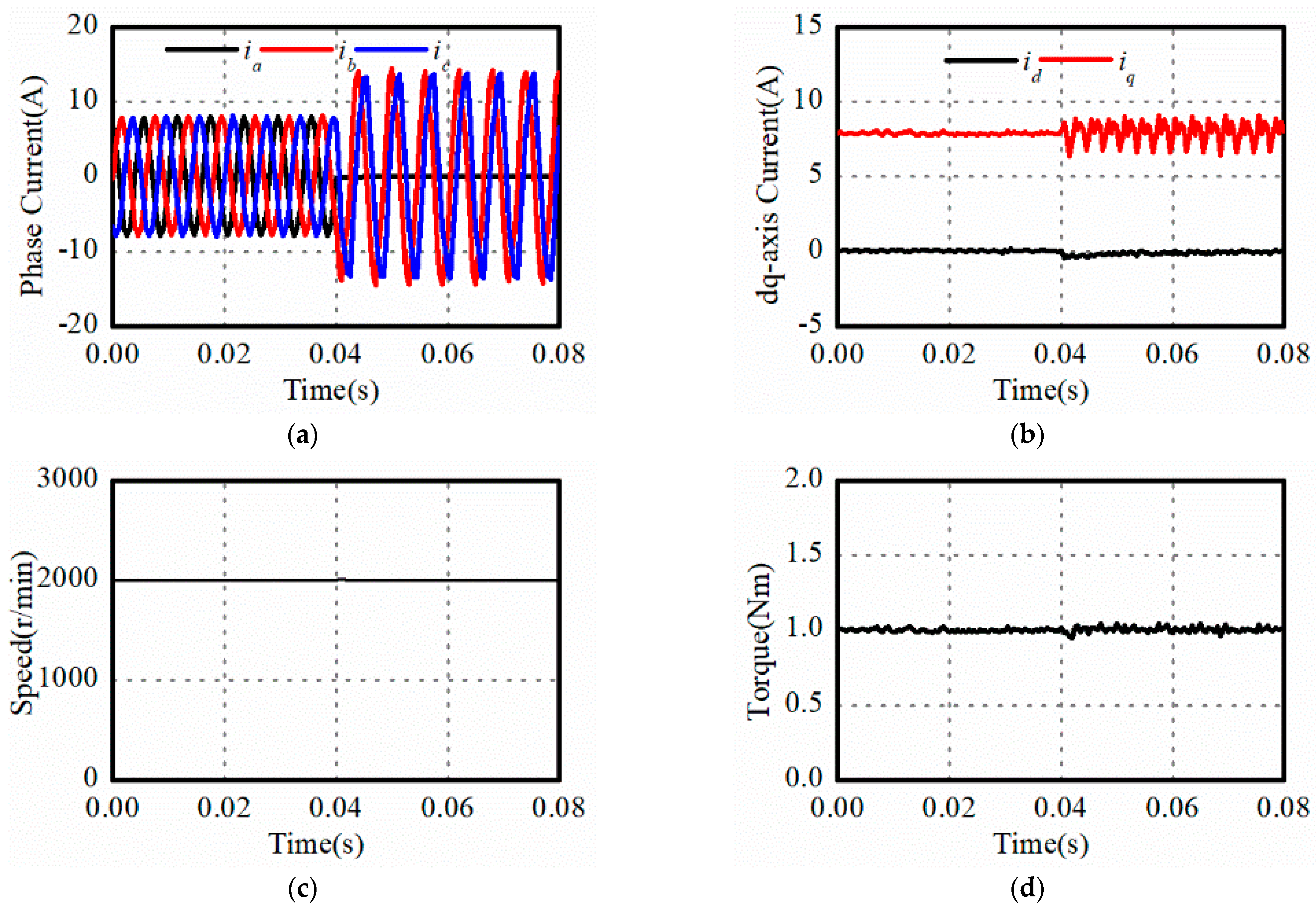
The simulated results of the proposed method before and after fault are shown in
Figure 3. The A phase open phase fault occurs in the drive system as 0.04 s, and then the control strategy switches from the normal operation strategy to the proposed fault tolerant control strategy. The load torque is 1 Nm. The effectiveness of the proposed control method is verified in
Figure 3. It can be found that the remaining current amplitude will increase to
times of the value under healthy conditions when the fault tolerant method is applied. In
Figure 3b, there are fluctuations in the
q axis current. Compared with healthy conditions, the
q axis current will be not constant. In addition, the
d axis current is always zero. Though the speed and torque both have little ripples after fault, the ripple has less influence on the drive system. Hence, the proposed method can realize the fault tolerant control operation of the drive system.
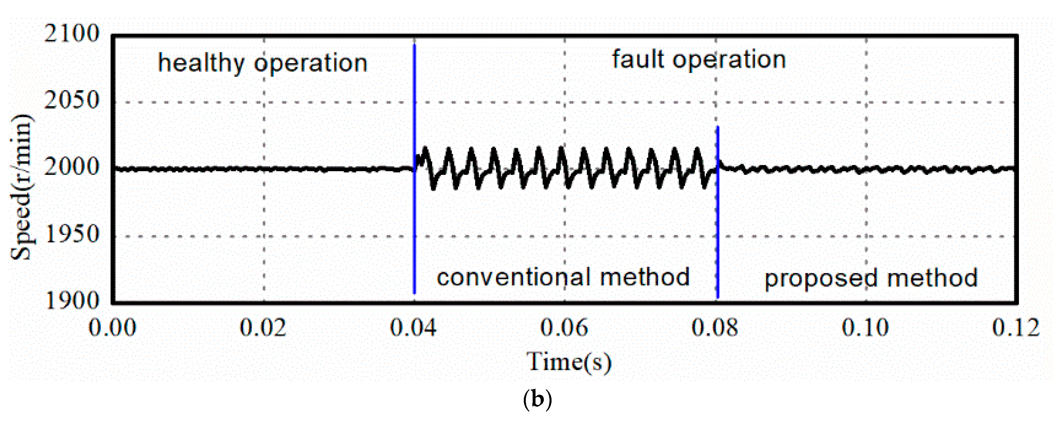
To demonstrate the superiority of the proposed method, the conventional method in [
18] is compared in this paper. The comparisons between the proposed method and the conventional method are shown in
Figure 4. In
Figure 4a, the torque ripple of the conventional method is 12% and that of the proposed method is 2%. The reduction of the torque ripple can reduce the speed ripple. In
Figure 4b, the speed ripple of the conventional method is ±15 r/min and that of the proposed method is ±1 r/min. By applying the proposed fault tolerant method, the torque ripple can be reduced effectively and the speed can be output more smoothly. According to
Figure 3 and
Figure 4, the proposed method can be verified effectively.
5. Experiment Verification
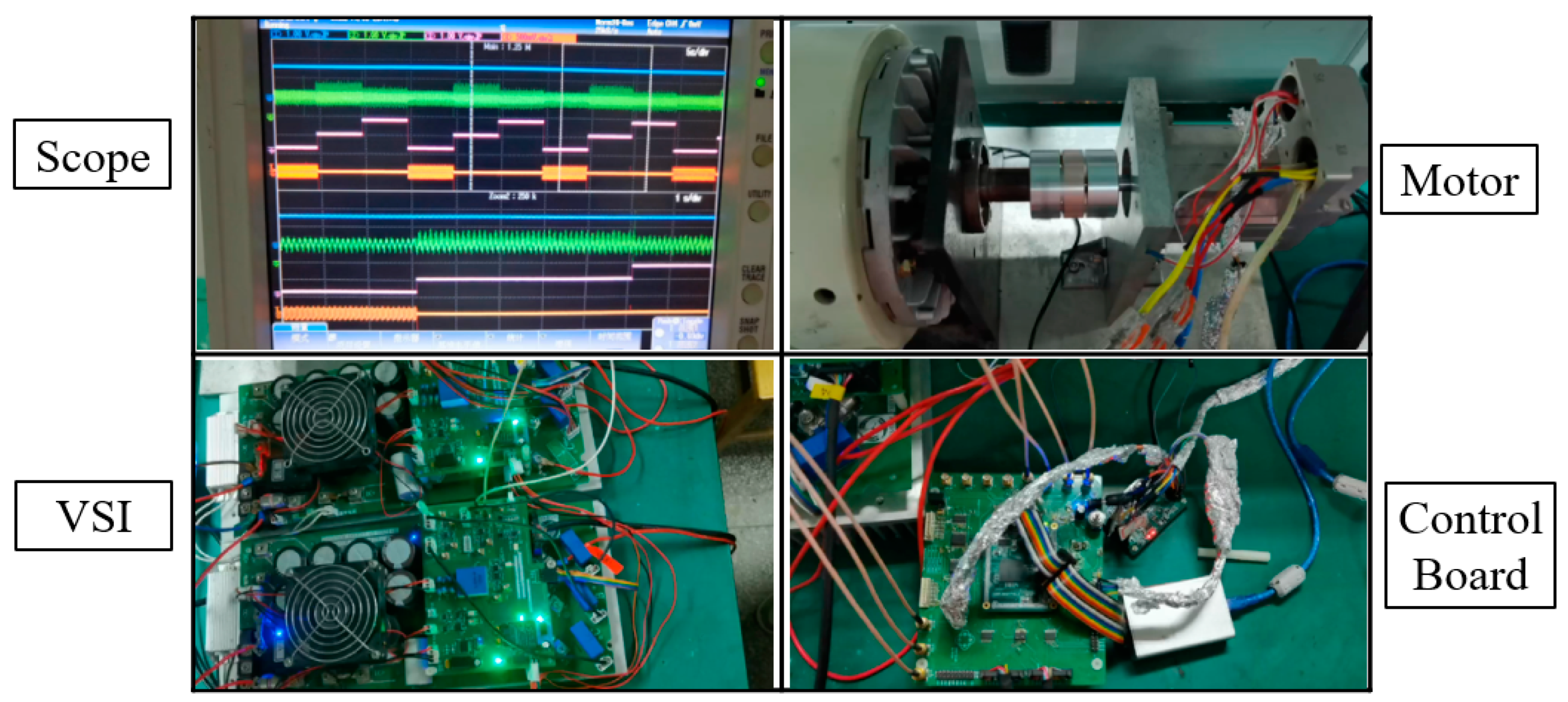
In this paper, an experimental setup is developed, as shown in
Figure 5. This experimental setup includes a scope, a motor, a voltage source inverter (VSI), a direct current (DC) power and a digital signal processor (DSP) control board. The motor parameters are listed in
Table 1. The switching frequency is 10 kHz. The motor operates at 500 r/min. Three operation conditions are compared in these experiments, including healthy condition, fault condition with conventional method and fault condition with our proposed method. For fault condition, the open phase fault of phase A is taken in the experiments.
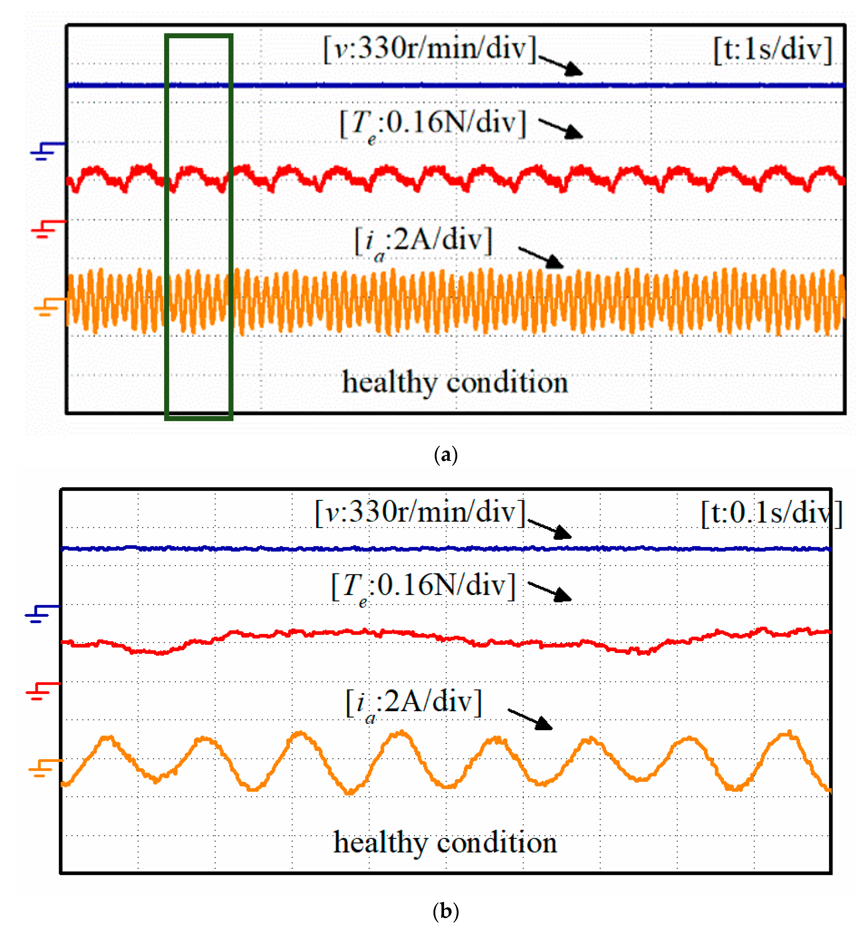
In experiment 1, the drive system operates at the healthy condition, as shown in
Figure 6. It can be found that there are some ripples in the torque. The electrical frequency is 41.67 Hz and the mechanical frequency is 8.33 Hz. The spectrum of the torque ripple is shown in
Table 2. The fundamental frequency is 8.33 Hz. It is shown that the main harmonic frequency of torque ripple is equal to the mechanical frequency. In each mechanical period, the low precision mechanical assembly and system friction will cause ripples in load. To maintain constant speed, the torque output of the system needs to match the load ripple. Hence, the low order harmonic’s ripple is a result from low precision mechanical assembly and system friction.
The ripples are mainly low order harmonics, which result from low precision mechanical assembly and system friction. Though there are some ripples in the torque, the speed is constant due to large moment of inertia from the end connected devices. Hence, only torque ripples are compared in these experiments.
In experiment 2, the drive system operates at the fault condition with the conventional method, as shown in
Figure 7. Compared with the healthy condition, the conventional method can realize the fault tolerance of the open phase fault. However, the torque ripple will be worse than the healthy condition. It can be found that high order harmonic torque ripples increase, which mainly result from the third harmonic flux.
In experiment 3, the drive system operates at the fault condition with the proposed method, as shown in
Figure 8. The torque ripple is slightly larger than that in the healthy condition. Compared the conventional method, the proposed method can reduce the torque ripple effectively. The high order harmonic torque ripple obviously decreases because the third harmonic flux is taken into consideration. The torque ripple can be reduced by 22%.
The spectrums of the torque ripples are shown in
Figure 9; the fundamental frequency is 41.67 Hz. It can be found that the proposed method can reduce the second and fourth harmonic ripple. By comparing these experiments, the effectiveness of the proposed method is verified.
6. Conclusions
In this paper, a fault-tolerant control method is proposed to cope with the open phase faults, which can significantly suppress the torque ripple after fault. The proposed control method mainly includes three parts: a torque-producing current calculator, phase voltage determination and voltage distributor. The torque-producing current calculator takes the third harmonic flux into consideration and calculates the q axis current based on the fundamental and third harmonic flux. The phase voltage determination calculates the phase voltage in the healthy and fault condition. It can unify the voltage distribution for both the healthy and fault condition, and reduce the changes in the control structure before and after fault. The voltage determination calculates the inverter voltage demand based on the maximum voltage utilization principle. The PI controller is applied for the regulation of the speed, d axis current and q axis current. After the regulation of the dq axis current, the cross decoupling part of the dq axis voltage is applied to calculate the dq axis voltage reference. In addition, the SPWM strategy is applied in the drive system. Finally, the proposed method is verified by simulated results and experimental results, in which three operation conditions are compared, including the healthy condition, fault condition with conventional method and fault condition with our proposed method. For further research, additional harmonic flux and friction disturbance will be taken into consideration.


