1. Introduction
In the 1960s, Berry et al. firstly proposed the concept of the reflectarray antenna [
1]. However, due to the large volume and heavy weight, the reflectarray antenna at that time was not highly valued. This was until the 1970s, with the development of printed circuit board (PCB) technology, when scholars began to use printed microstrip elements produced by PCB technology to design reflectarray antennas. In 1978, C.S. Malagisi firstly proposed the use of microstrip patch elements as phase modulation units for reflectarray antennas, which have advantages such as light weight, low profile, and easy conformability [
2]. In 1987, R.E. Munson applied for a US patent for a microstrip reflectarray antenna, which gave rise to the concept of the microstrip reflectarray antenna (RA) [
3].
RAs, as substitutes for traditional reflectors, have received widespread attention in recent years. Many studies have investigated the design of circularly polarized reflectarrays [
4,
5,
6,
7,
8,
9,
10,
11,
12,
13,
14,
15,
16,
17,
18,
19]. The advantages of circularly polarized electromagnetic waves include the ability to overcome multipath effects and the interference of rain and fog and to solve polarization matching problems. Therefore, circularly polarized antennas are widely used in deep space exploration, remote sensing and telemetry, satellite communication, and other fields.
According to the type of feed, circularly polarized reflectarray antennas (CPRAs) can be divided into two categories: CPRAs with circularly polarized (CP) feeds or with linearly polarized (LP) feeds. CPRAs with CP feeds are mostly based on rotating elements [
4,
5,
6,
7,
8], and the required phase compensation is obtained by changing the rotation angle of the rotating elements. However, as the frequency of electromagnetic waves increases, especially when working in the millimeter wave, terahertz, or higher bands, the difficulty in designing and processing CP feeds increases sharply. Therefore, scholars have begun to study CPRAs with LP feeds. Multiple types of elements have been reported for CPRAs with LP feeds, including square patch and cross slot dual-layer elements [
9], dual-layer rectangular patch elements [
10], dual-layer T-shaped elements [
11], split square ring elements [
12], dual-layer Jerusalem-shaped elements [
13], and double-layered elliptical microstrip patch elements [
14].
The state of the art on CPRAs has made significant steps in recent years, such as dual-band CPRAs [
15,
16,
17], circularly polarized reflect-transmit-array antennas [
18], and beam-scanning CPRAs [
19]. However, due to the high machining accuracy required for W-band RAs, there are only a few studies on W-band CPRAs, and most of them remain in the simulation stage without fabrication and measurement. Therefore, the study of W-band CPRAs is of great significance.
In our study, a W-band single-layer broadband circularly polarized reflectarray antenna was proposed, which contains a low-profile reflectarray and a linearly polarized horn antenna. Firstly, we designed and analyzed a single-layer multi-resonant element for our proposed CPRA, including a Rogers RT5880 substrate with copper patches printed on both its surfaces. The simulation results showed that elements can independently control the reflected wave phase in two orthogonal directions by changing the corresponding parameters and can achieve a smooth phase shift range of over 360° in both orthogonal directions. Then, we designed and manufactured a planar circular reflectarray consisting of 437 elements and further verified of our proposed element.
2. The Design of the Reflectarray Element
The reflectarray of CPRAs with an LP feed needs the ability to convert LP incident waves into CP reflected waves. Based on electromagnetic theory, CP waves are composed of two spatially orthogonal LP waves with equal amplitudes and phase differences of π/2. Therefore, the designed reflectarray should be able to generate different reflective phases for LP incident waves in two orthogonal directions to obtain a 90° phase difference between the two orthogonal parts of the reflected wave to obtain CP waves. Meanwhile, each reflectarray element is necessary to bring the appropriate reflective phase to compensate the spatial phase delay, so as to imitate the ability of the traditional reflector.
Among the basic structures of reflectarray elements, the dipole has the ability to change the reflective phase of the LP incident wave in the corresponding direction by adjusting the length, while almost having no effect on the reflective phase of the LP incident wave in its orthogonal direction. Meanwhile, the structure of the dipole is simple, small, and easy to integrate into multi-resonant structures. Thus, the dipole has advantages in the high-precision processing of W-band antennas. The combination of dipoles can be used to design W-band circularly polarized reflectarray elements.
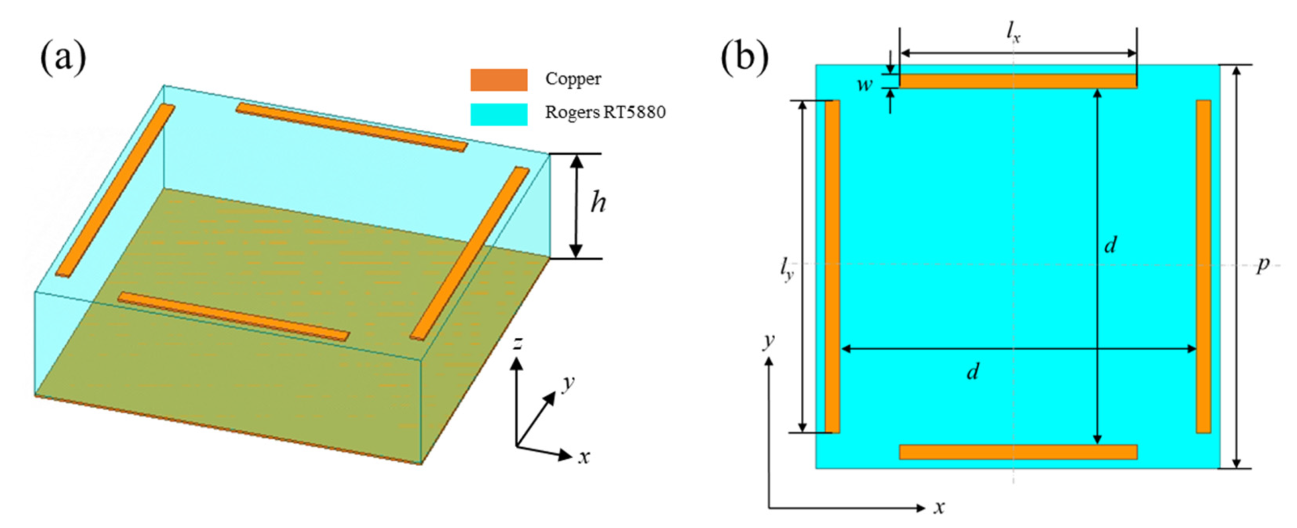
As shown in
Figure 1, a reflectarray element is formed by four dipoles. The
lx and
ly can be independently changed, so the element is not a completely symmetrical structure. The substrate material is Rogers RT5880, with a thickness of 0.508 mm.
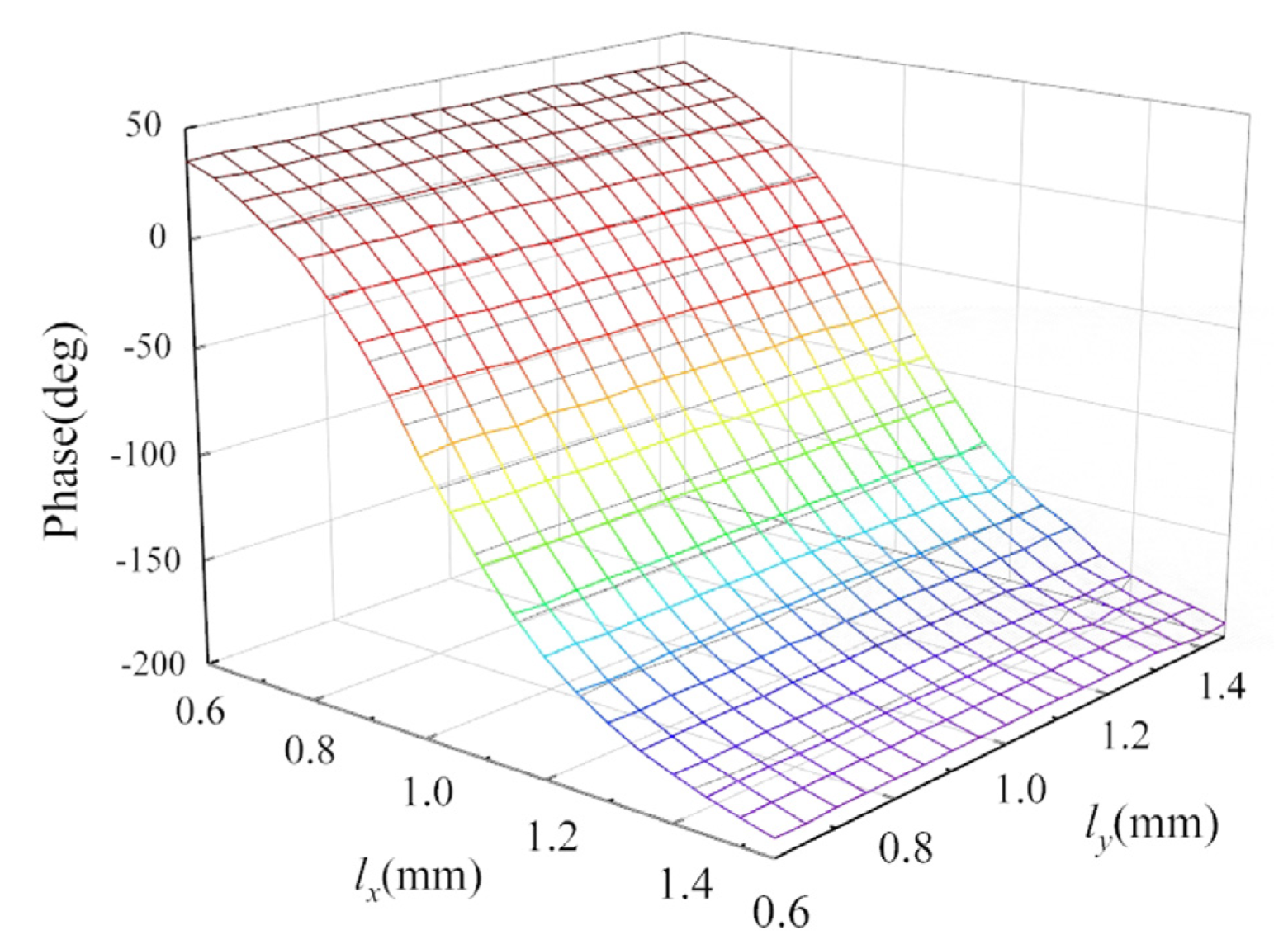
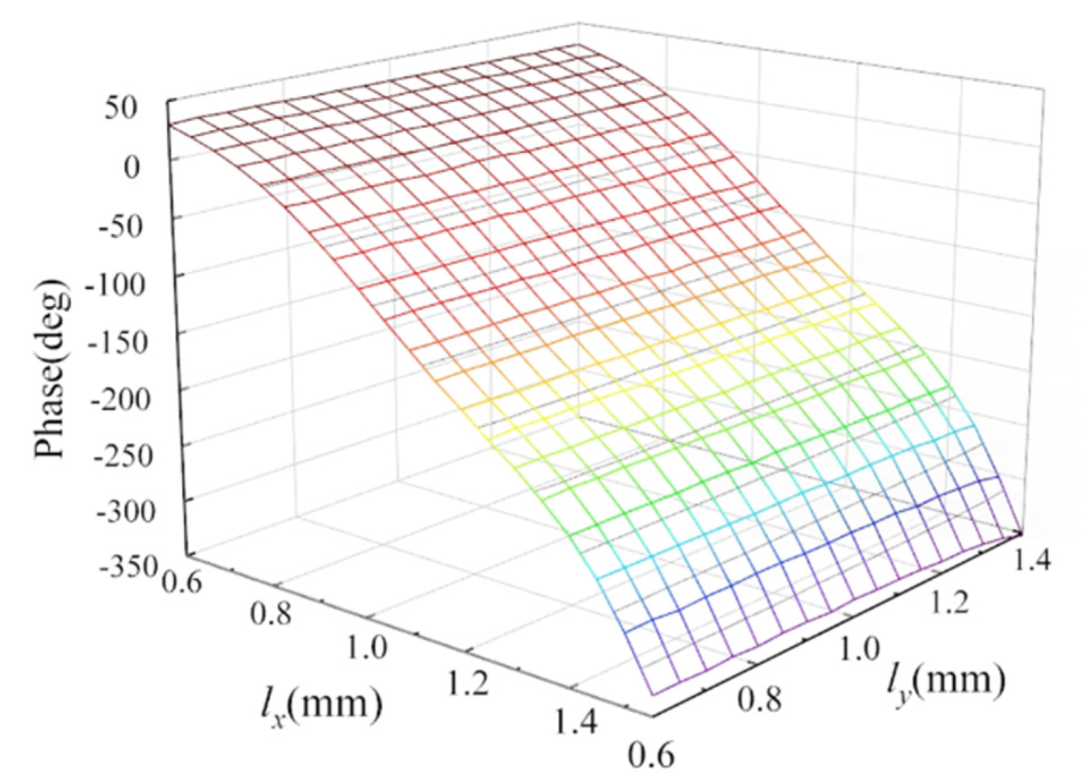
The simulation results of this element, where the incident wave is an LP wave in the X direction, are shown in
Figure 2. It can be seen that for an LP incident wave paralleled to the X axis, the phase shift of the reflected wave is more sensitive to the changes in the parameter
lx, while the change in the parameter
ly has little effect on its reflective phase. We can assume that the reflective phase of the LP incident wave paralleled to the X axis is only determined by
lx. Similarly, the reflective phase of the LP incident wave paralleled to the Y axis is only determined by
ly. Therefore, the reflective phases of the LP incident waves paralleled to the X axis or Y axis can be independently obtained by changing the values of
lx or
ly.
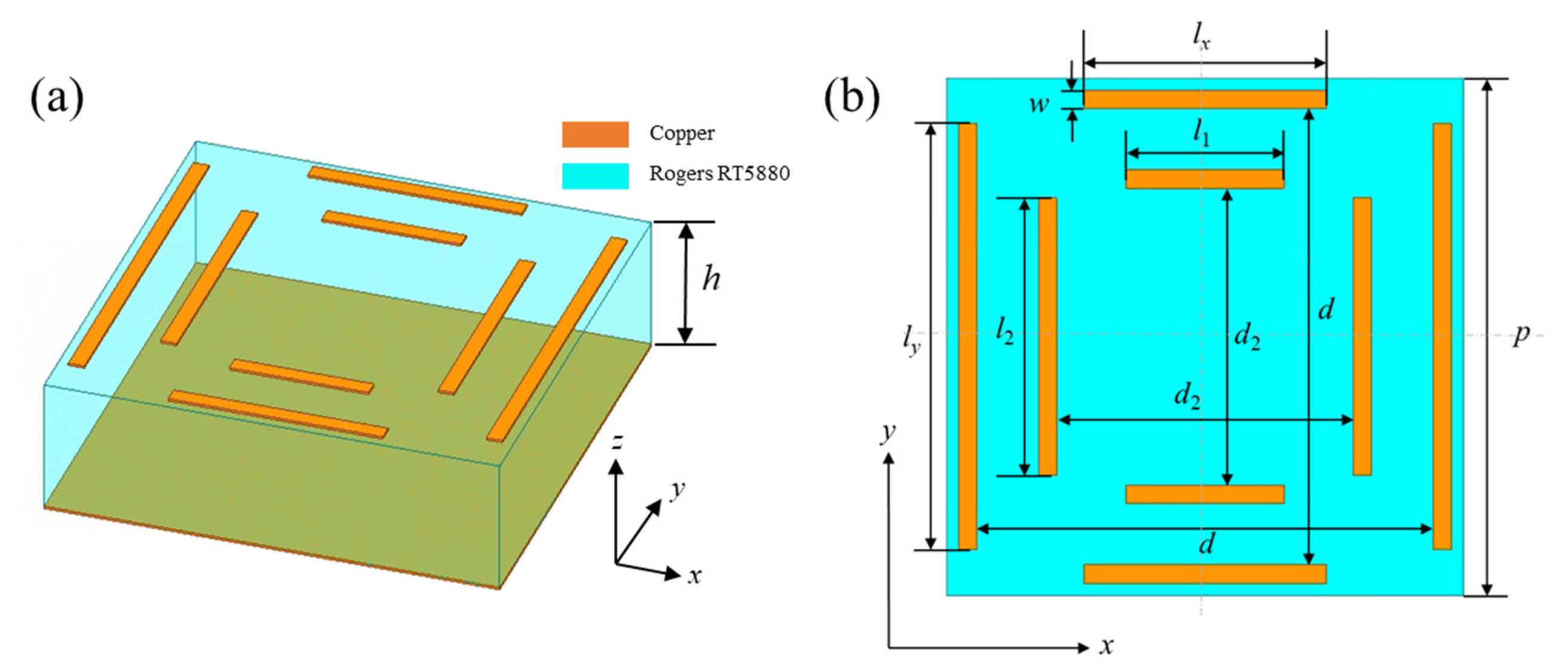
However, this single-resonant element cannot meet the demands of designing RAs because its reflective phase shift range is only about 250°. To change the resonance characteristic of the element, four additional dipoles were added into our proposed element to obtain a single-layer multi-resonant element.
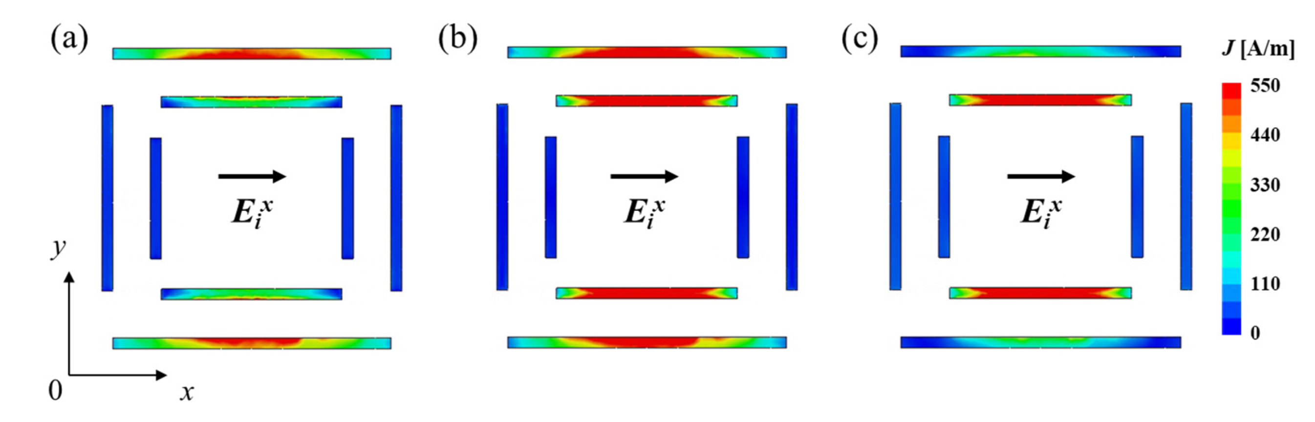
Figure 3 shows the structure of our proposed single-layer multi-resonant element. It contains a dielectric substrate (Rogers RT5880, blue part) with metal patches (copper, orange parts) printed on its both surfaces. To show three typical resonant forms of the element more intuitively, the simulated surface current distributions of the multi-resonant element with E
ix at three different frequency points are shown in
Figure 4. When the frequency is 84 GHz, the surface current of the outer dipole is strong, while the inner dipole is weak. When the frequency is 94 GHz, the surface current distribution intensity of the inner and outer dipoles is equivalent. When the frequency is 104 GHz, the surface current of the outer dipole is weak, while the inner dipole is strong. We can see the variation in surface current distributions with different frequencies. As the frequency increases, the surface current of the outer dipole gradually decreases, while the surface current of the inner dipole gradually increases.
In the realization of reflectarrays, element spacing is an important factor. Too large element spacing will lead to the generation of grid lobes in the antenna pattern. We can use Equation (1) to calculate the proper element spacing
p so as to avoid this problem [
20]:
where
λ0 is the electromagnetic wave length at the center frequency and
θ is the maximum angle of incidence from the feed.
With the center frequency of 94 GHz, considering the limitation in the range of phase shift and practical manufacture, we chose an element spacing of 0.53 λ0. Therefore, the parameter p is 1.7 mm.
Microstrip reflectarrays are fabricated by PCB technology. The minimum line spacing is an important limiting factor in the process of PCB technology. In addition, the thicknesses of the boards used in the fabrication process have some fixed standards. We chose a substrate with a thickness of 0.508 mm. Then, we proposed a coefficient
k, where
d2 is equal to
k ×
d,
l1 is equal to
k ×
lx, and
l2 is equal to
k ×
ly, and further optimized the structure parameters by using simulation software. To design the reflectarray elements, two requirements should be met. Firstly, the phase shift range of the element needs to exceed 360°. Moreover, the phase shift curve needs to be flat and have good linearity, which can effectively expand the bandwidth of the antenna. In our proposed element, the parameter
k is a significant structure parameter because it can affect the coupling between the outer and inner dipoles. The parameter
k could affect the distance and strength of the resonance points of the proposed element. With a decrease in parameter
k, the distance between the inner and outer dipoles increases, so that the coupling effect weakens. It also leads to the increase in the spacing between resonance points and the decrease in intensity of the resonance points. The parameter
w is the width of each dipole and it also has a significant impact on the reflection performance of the element. With a decrease in parameter
w, the dipoles become thinner, so that the position of each resonance point moves towards the right in the coordinate axis. Meanwhile, the strength of resonance points increases, but the distance between the resonance points does not change much. The parameter
d has little effect on the position of the resonance point, it only slightly affects the strength of the resonance point. However, if the parameter
d is too small, it will affect the allowable size range of
lx or
ly. If the parameter
d is too large, it will exacerbate the coupling between the adjacent elements, resulting in a change in the actual reflection phase shift of the element and further causing the decreased gain of the antenna. Therefore, in the design of multi-resonant broadband reflectarray elements, the selection of the parameter
d should be moderate. We can see the optimized parameters of the single-layer multi-resonant element in
Table 1.
The master–slave boundary method with Floquet port excitations is a commonly used method to build and simulate the reflectarray element.
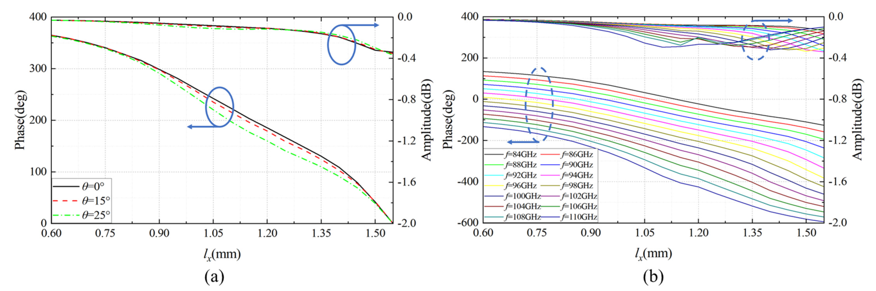
Figure 5 shows the reflective phase shift performance of the proposed reflectarray element with E
ix. It can be seen that for incident waves paralleled to the X axis, the phase shift of the reflected wave is more sensitive to the changes in the parameter
lx, while the change in the parameter
ly has little effect on its reflective phase. As shown in
Figure 6a, when
ly is 1 mm and
lx varies from 0.600 to 1.532 mm, at the center frequency of 94 GHz, the phase shift range of the reflected wave is larger than 360° and the amplitude is larger than −0.34 dB. The frequency sweep results ranging from 84 to 110 GHz are shown in
Figure 6b. We can see that when the frequency changes, the reflection characteristics of the element also change. The reflection phase shift range of the element is positively correlated with the frequency. As the frequency decreases, the reflection phase shift curve tends to be flat and the reflection phase shift range decreases. Conversely, the reflection phase shift range increases. However, the whole change is not significant and the reflection phase shift curves are approximately parallel. It means that, within a relatively wide frequency band, the element can provide a reflection phase shift that is not significantly different from that required. Our proposed element has good broadband performance due to its approximately identical phase compensation characteristic at different frequencies.
3. The Design and Realization of RA
Choosing optimum phase distribution in the reflectarray aperture is the key to obtaining an RA with high gain and aperture efficiency. We can use Equation (2) to obtain the optimum value of required phase
of each element in the coordinate plane across the reflectarray:
where
k is the wavenumber,
Ri is the distance between the phase center and the
ith element,
is the position vector of the
ith element,
is the unit vector in the main beam direction, and
is the relative phase [
21].
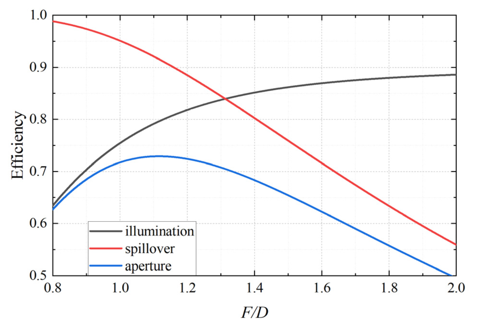
To design the aperture phase distribution, firstly, we should choose the proper focal distance
F and aperture size
D. The focus-to-diameter ratio (
F/D) is a key factor to obtain a higher aperture efficiency of the RA. In our research, the feed we chose is a horn antenna with a 17 dBi gain at the center frequency of 94 GHz. Based on reflectarray theory, spillover efficiency
ηs and illumination efficiency
ηi are the most important factors affecting the value of aperture efficiency
ηa. And the increased
F/D value leads to lower spillover efficiency
ηs and higher illumination efficiency
ηi [
22]. Therefore, the proper
F/D value can be chosen as 1.116, which means that the maximum angle of incidence from the feed is about 24.13°, as shown in
Figure 7. To ensure a sufficiently high gain of the antenna, we chose the planar circular reflectarray containing 437 elements; thus, the aperture diameter
D is 12.25
λ0 (39.1 mm) and the focal distance
F is 47.43 mm.
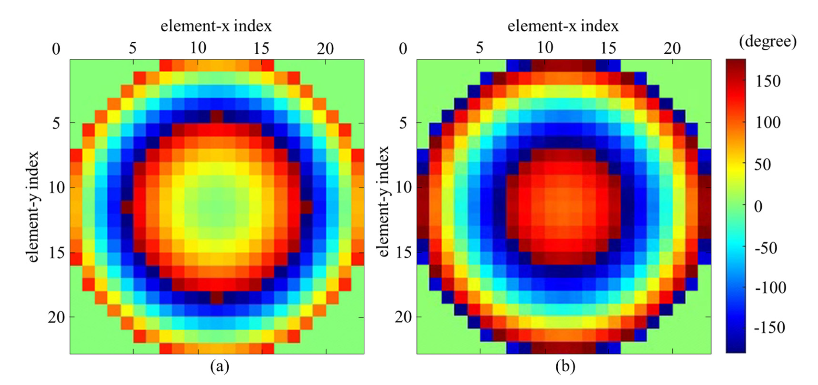
After determining the
F/
D value, the optimum required phases of each element in the coordinate plane across the reflectarray can be calculated by Equation (2). The required compensation phases of the X-direction incident wave differ by 90° from the Y-direction incident wave, as shown in
Figure 8, because the reflectarray needs the ability to convert LP incident waves into CP reflected waves.
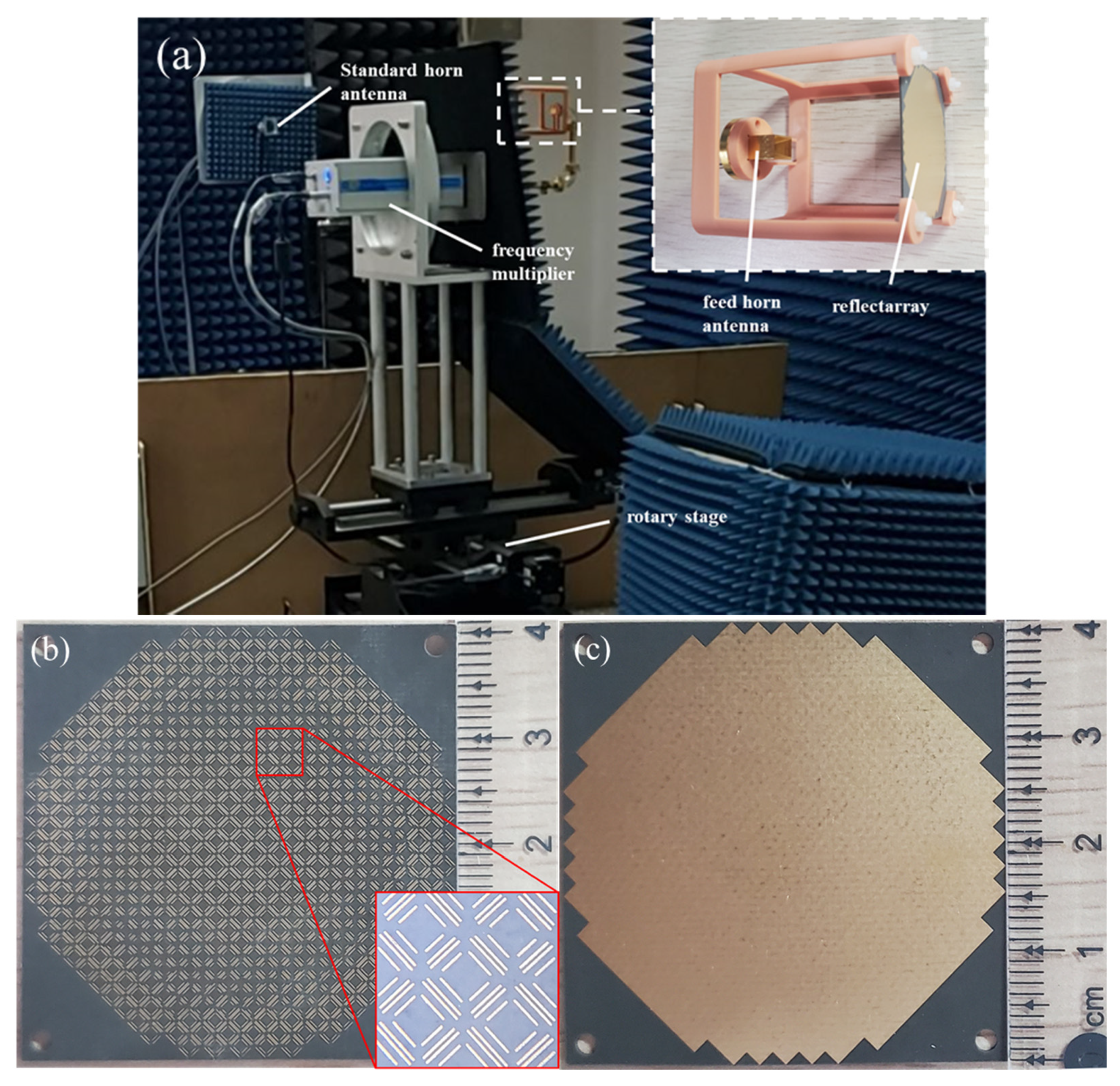
Then, we simulated, fabricated, and tested our proposed RA. To test the gain performance of RAs, a far-field measurement system with a 1 GHz frequency resolution was used. As shown in
Figure 9a, the reflectarray and the feed horn are fixed by the plastic bracket and then connected to the frequency multiplier and the vector network analyzer.
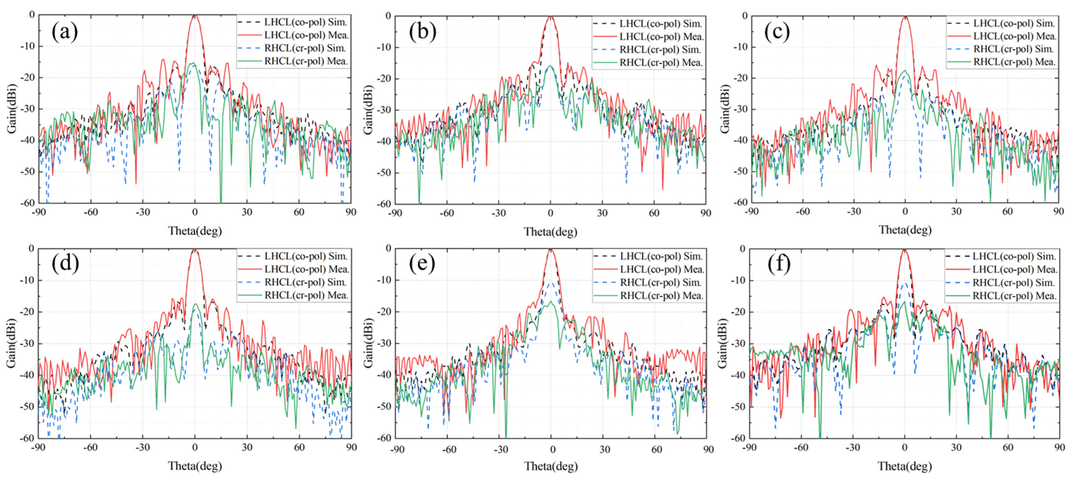
Figure 10 shows a good consistency between the simulated and measured results at the three different frequency points. We can see that, at the center frequency of 94 GHz, the value of the measured side-lobe in the E plane is as low as −16.2 dB and in the H plane it is −15.7 dB, and the value of measured cross-polarization is as low as −17.4 dB. Moreover, the maximum measured side-lobe is −14.5 dB in the H plane at 89 GHz. The larger connecting flange and the occlusion by metal waveguides are significant reasons leading to the differences between the radiation patterns of simulated and fabricated RAs.
Moreover,
Figure 11 shows the result of the axial ratio and antenna gain of our proposed RA. At 94 GHz, the measured gain reached 29.1 dBi and the corresponding aperture efficiency reached 52.0%. The 1 dB gain bandwidths and 2 dB gain bandwidths of the designed RA are 19.1% and 27.6%, respectively. The 3 dB axial ratio bandwidth is 13.8%, ranging from 89 GHz to 102 GHz. We found that the small differences between the antenna gain and axial ratio of our proposed RA may be caused by the feed blocking and the discrepancies between the fabricated and simulated reflectarrays. The PCB process used in our proposed reflectarray has a fabrication tolerance of −0.006~0 mm. Under the condition of a manufacturing error of −0.006 mm, the average phase compensation error of the element is 2.30° and the max error is about 5.04°. Due to the phase compensation errors, the gain of the RA will decrease and the axial ratio will also change.
A comparison between our work and related RAs in the W-band or higher bands is shown in
Table 2. Our proposed CPRA converts the LP wave emitted by the feed into the CP wave. The incident of our feed is at a 45° angle to the coordinate axis. The incident wave is divided into two orthogonal components and then converted into a CP wave by changing the phase difference between the two components. Therefore, this type of CPRA has a gain 1.5 dBi lower than the LPRA with same aperture and feed, and the aperture efficiency is correspondingly much lower. Moreover, due to the high machining accuracy required for W-band RAs, there are a few studies about W-band CPRAs, and most of them remain in the simulation stage without fabrication and measurement. Considering this characteristic, our proposed CPRA has undergone processing and measuring. It has advantages in the comprehensive performance of the polarization mode, aperture efficiency, and bandwidth.


 ,
, 

