Abstract
As the penetration of renewable energy increases year by year, the risk of high-frequency oscillation instability increases when a three-phase, four-wire split capacitor inverter (TFSCI) is connected to the grid with complementary capacitors in weak grids. Compared to the three-phase, three-wire inverter, the TFSCI has an additional zero-sequence current loop. To improve the accuracy of the modeling and stability analysis, the effect of the zero-sequence loop needs to be considered in the impedance-based stability analysis. Therefore, a correlation model considering multi-perturbation variables is first established, based on which the inverter positive, negative, and zero sequence admittance models are derived, solving the difficult problem of impedance modeling under small perturbations. Secondly, an admittance remodeling strategy based on a negative third-order differential element and a second-order generalized integrator (SOGI) damping controller is proposed, which can improve the stability of positive, negative, and zero-sequence systems simultaneously. Finally, the effectiveness of the oscillation suppression strategy is verified by simulation and experiment.
1. Introduction
In order to achieve the goals of energy conservation and carbon reduction, the penetration rate of renewable energy generation systems represented by solar energy and wind energy has increased every year, and grid-connected inverters have been widely used in power systems as energy conversion bridges between new energy power generation systems and power grids [1,2,3,4,5]. In the distribution network and microgrid, the three-phase, four-wire inverter has a zero-sequence current loop, which is suitable for both symmetrical and asymmetrical operating conditions and has a high DC utilization rate. Therefore, the system has been widely used in engineering [6]. On the one hand, renewable energy power generation systems are usually connected to the grid through transformers or long-distance transmission lines, making the grid gradually exhibit weak grid characteristics. The influence of grid equivalent impedance on system stability cannot be ignored [7,8]. On the other hand, new energy power generation systems often use parallel compensation capacitors to improve grid-connected power quality and reduce line losses [9]. The stability margin of the three-phase, four-wire inverter, when connected to a weak electric grid with parallel compensating capacitors, is relatively low for positive, negative, and zero-sequence conditions. The interaction between the grid-tied inverter and the public power grid results in high-frequency oscillations in the system, posing a serious threat to the stable operation of the power system [10,11].
In order to suppress the oscillation phenomenon of grid-connected inverter systems, domestic and foreign scholars have carried out a lot of research on its instability mechanism and high-frequency oscillation suppression strategy. References [12,13,14] compared the power electronic system to the traditional power system, and tried to use the second-order differential equation similar to the power angle motion to explain the dynamic instability mechanism of the inverter. Reference [15] analyzed the mechanism of interaction instability between the grid impedance and grid-tied inverters from a damping perspective using a small-signal model for the grid-tied inverter system. The above reference studies the oscillation mechanism of a grid-connected inverter system from different angles. Based on the related research of system oscillation mechanism, reference [16] improves the amplitude and phase of the inverter by parallel virtual impedance and series virtual inductance, thereby improving the output impedance characteristics of the inverter at the oscillation frequency. Reference [17] realized active damping by shaping the current loop and voltage loop of the inverter to improve the stability of the grid-connected inverter system. Reference [18] proposed adding source PWM inverter impedance reconstruction control to the double-loop control strategy to improve the inverter output impedance phase and increase the system’s high-frequency damping. In [19], the resonant damping control of the inverter is realized by feeding back the quadratic differential term of the grid-connected current. This method is easy to implement without additional sensors. References [20,21] constructed a small-signal impedance model for inverter direct power control without a phase-locked loop and proposed a phase-locked loop-free control scheme. This scheme improves the phase margin in the phase-locked loop frequency band of the system by reducing the negative resistance frequency band of the system, thereby reducing the risk of system oscillation instability caused by traditional phase-locked loops. In [22], a band-pass filter is introduced into the phase-locked loop, and an adaptive control method of grid voltage feedforward with proportional and differential feedforward is proposed. The scheme reduces the risk of system instability by adjusting the control parameters in real-time. However, most of the existing research on oscillation suppression in grid-tied inverters focuses on three-phase, three-wire systems and does not consider the influence of zero-sequence circuits during modeling. In contrast, three-phase four-wire inverters introduce an additional path for zero-sequence current compared to three-phase three-wire inverters. In order to enhance the accuracy of the stability analysis for three-phase, four-wire inverters and improve their stability, it is necessary to consider the influence of both positive, negative, and zero-sequence circuits when applying impedance stability theory for stability analysis. This comprehensive approach ensures a more accurate assessment of the inverter’s stability. At present, there are few studies on small signal impedance modeling of a three-phase, four-wire inverter, and high-frequency oscillation suppression methods considering the zero-sequence component. Therefore, the instability mechanism and oscillation suppression strategy of a three-phase, four-wire inverter system need to be further studied.
Therefore, this paper takes the three-phase, four-wire split capacitor inverter (TFSCI) system as the research object, establishes the small signal correlation model of the inverter considering the disturbance of grid voltage, inverter current, and duty cycle variables, and deduces its positive, negative, and zero sequence admittance model, which solves the small disturbance impedance modeling problem considering the dynamic characteristics of the phase-locked loop. Subsequently, the risk of positive, negative, and zero-sequence instability of the inverter connected to the grid with a shunt capacitor is analyzed. An admittance-reshaping oscillation suppression strategy based on a second-order generalized integrator (SOGI) and a negative third-order differential element is proposed to improve the stability of positive, negative, and zero-sequence systems of TFSCI. The influence of the main control parameters on the stability of the system is analyzed. Simulation and experiment verify the effectiveness of the three-phase, four-wire inverter oscillation suppression strategy under a weak grid. The flowchart of the research methodology is shown in Figure 1.
Figure 1.
The flowchart of research methodology.
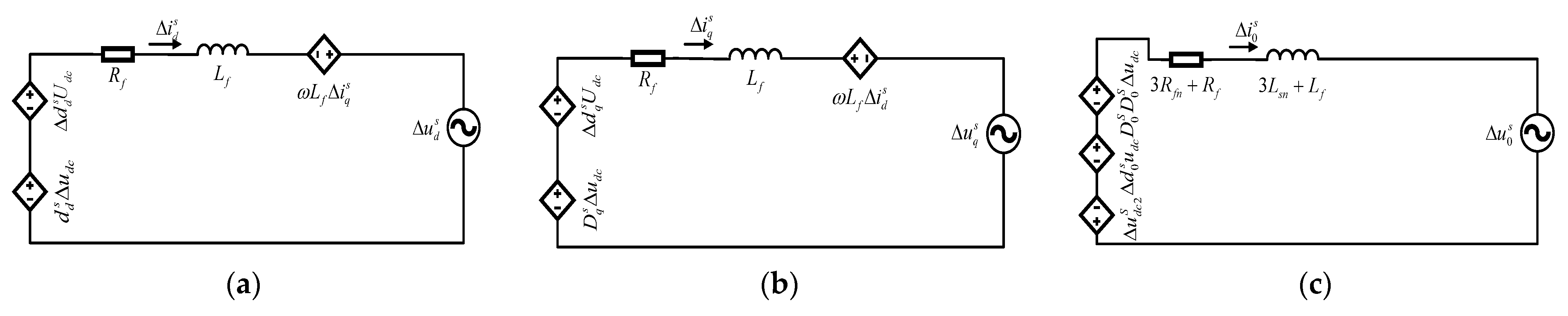
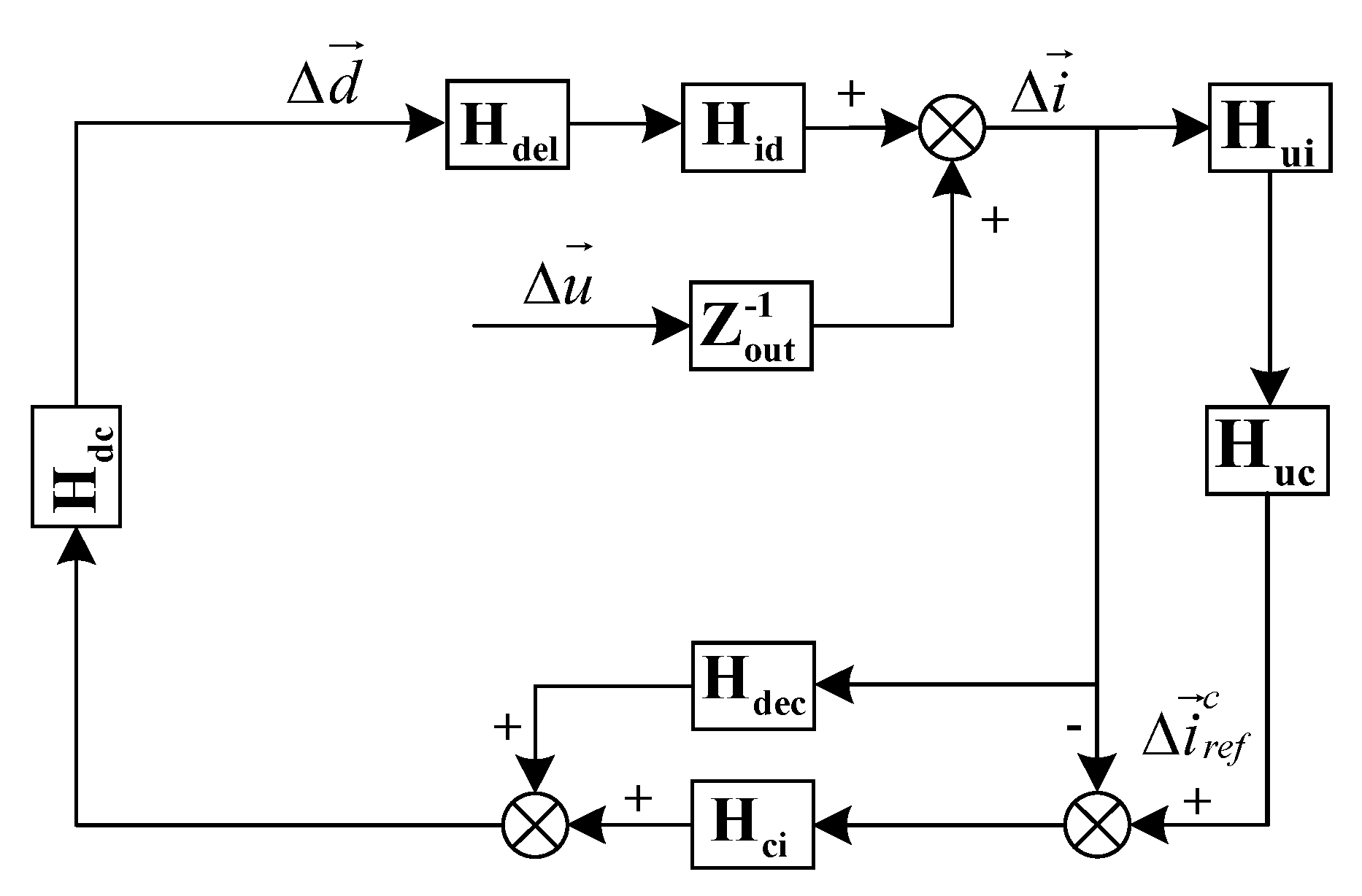
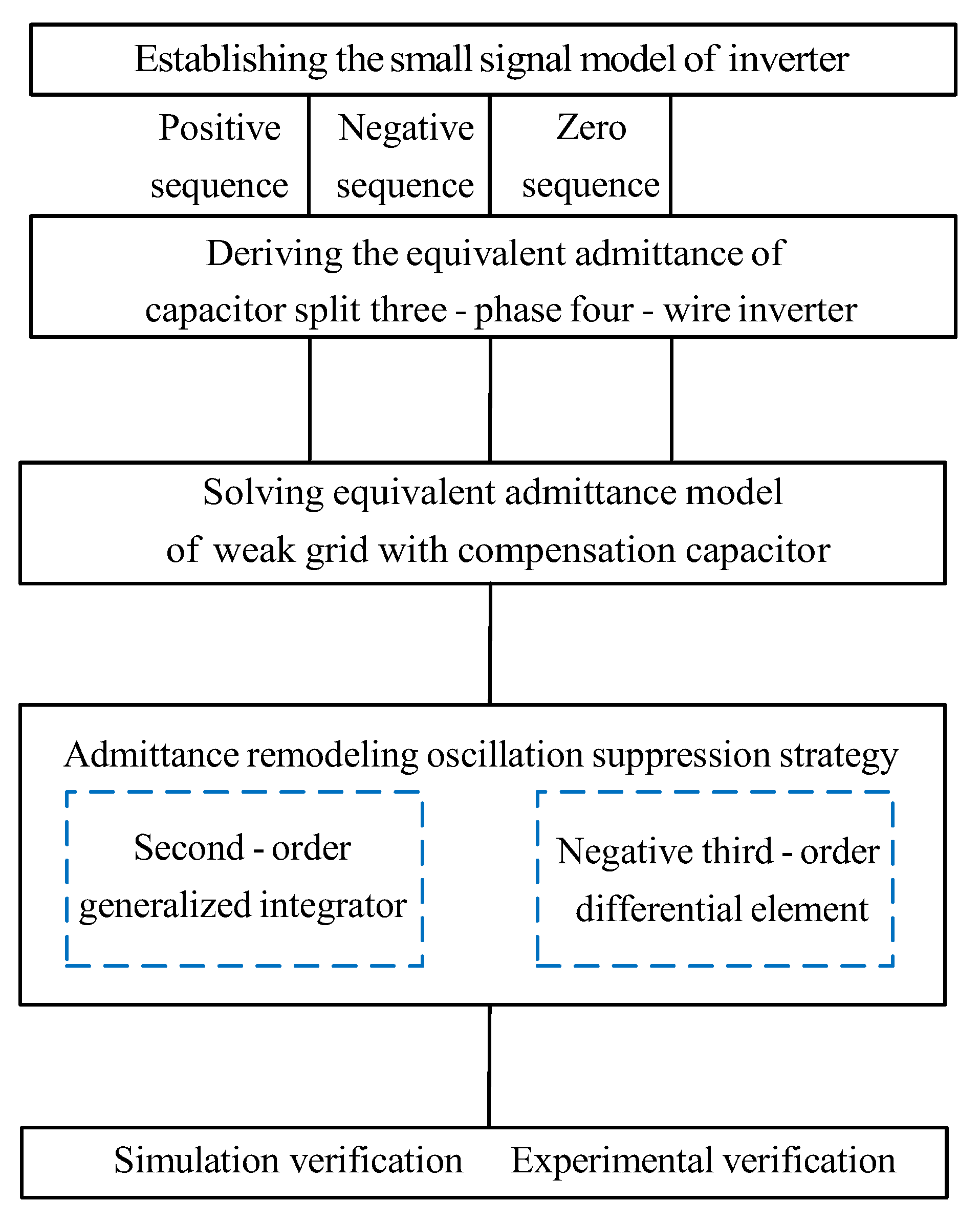
2. Research on the Admittance Model of Three-Phase Four-Wire Grid-Connected Inverter
In order to analyze the admittance characteristics and stability of the typical three-phase four-wire inverter system, this section will focus on the derivation of the admittance model of the TFSCI. Due to the main focus of this article being the admittance characteristics of inverters in the high-frequency range within a weak power grid, the influence of the phase-locked loop (PLL) on the output characteristics in this frequency range is considered to be minimal. Therefore, when modeling the system, the impact of the PLL is neglected. Figure 2 shows the equivalent control block diagram of the TFSCI connected to the grid. In Figure 2, and is the DC side capacitor of the inverter, and n is the midpoint of the DC side capacitor.
Figure 2.
Equivalent control block diagram of TFSCI connected to power grid.
In order to derive the equivalent admittance of the TFSCI, the small signal model of the inverter is established below. Firstly, assuming the DC-side capacitor voltage , due to the DC-side voltage fluctuation , the zero-sequence current of the inverter can be derived as:
In the formula, and is the DC side capacitor and the voltage on both sides.
In theoretical analysis, it is common to transform the three-phase circuit model of the inverter into the d-q-0 coordinate system in order to achieve decoupled control of active and reactive currents. For this reason, assuming that the filter inductance and the filter inductance parasitic resistance in Figure 2, the Kirchhoff voltage equation is written for the inverter control loop and the Park transformation is performed. The small signal model of the inverter in the d-q-0 coordinate system can be obtained:
In the formula, is the DC side voltage of the inverter. , , are the control signals used to control the switching state of the inverter. , , are the three-phase current output by the inverter in the d-q-0 coordinate system. , and are the three-phase voltage output by the inverter in the d-q-0 coordinate system with the g point as the reference, p represents the differential operator d/dt.
The expressions for the positive, negative, and zero sequence admittance of the TFSCI, as derived in Appendix A based on Equation (2) combined with the small-signal control block diagram of the inverter, are as follows:
3. Stability Analysis of Three-Phase Four-Wire Grid-Connected Inverter with Shunt Capacitor in Weak Grid
In order to analyze the stability of TFSCI in a weak grid, it is necessary to solve the positive, negative, and zero-sequence equivalent admittance models of a weak grid with a shunt capacitor. Due to transformer leakage inductance, long-distance transmission lines, and other reasons, a weak grid usually presents the significant characteristics of high inductive impedance and a low short-circuit ratio. At this time, the inductive impedance of the grid-side grid cannot be ignored. Figure 3 shows the circuit model of the TFSCI connected to the weak grid with a shunt capacitor. In Figure 3, and respectively represent the grid equivalent inductance and the inverter midline equivalent inductance, and respectively represent the parasitic resistance corresponding to the grid equivalent inductance and the parasitic resistance corresponding to the inverter midline equivalent inductance, and respectively represent the grid parallel compensation capacitance and its parasitic resistance. According to the circuit theorem, the positive, negative and zero sequence admittance of the power grid with shunt capacitor are:
Figure 3.
Circuit model of TFSCI connected to weak grid with parallel compensation capacitors.
According to the admittance stability theory, the phase margin of the inverter-grid interconnected system is:
In the formula, represents the equivalent impedance of the grid in the d-q-0 coordinate system, represents the equivalent impedance of the inverter under the d-q-0 axis, and fc represents the intersection frequency of the inverter and the grid admittance.
In order to verify the correctness of the established admittance model and clarify the stability of the TFSCI when it is connected to the grid with a shunt capacitor under a weak grid, Figure 4 and Figure 5 show the frequency sweep diagram of the admittance model of the TFSCI and the admittance Bode diagram of the TFSCI and the grid with a shunt capacitor. In order to simulate the weak grid environment, the equivalent inductance Lg of the grid under the weak grid is set to 2 mH. Comparing Figure 4 and Figure 5, it can be seen that the frequency sweep results of the TFSCI are consistent with the admittance curve of its admittance model, which verifies the correctness of the model built in this paper. Further observation of Figure 5 shows that the intersection of the positive, negative, and zero sequence admittance of the inverter and the grid admittance amplitude is at 2000 Hz, 2000 Hz, and 239 Hz, respectively. Based on admittance stability theory and practical engineering experience, the positive, negative and zero sequence stability margins of the inverter system are , and . In summary, there is a risk of oscillation instability when the TFSCI is connected to the grid with shunt capacitors.

Figure 4.
Frequency scanning plot bode diagram of TFSCI admittance model. (a) positive sequence. (b) negative sequence. (c) zero sequence.

Figure 5.
Admittance bode diagram of TFSCI and power grid with parallel compensation capacitors. (a) positive sequence. (b) negative sequence. (c) zero sequence.
4. Research on High Frequency Oscillation Suppression Strategy of Three-Phase Four-Wire Grid-Connected Inverter
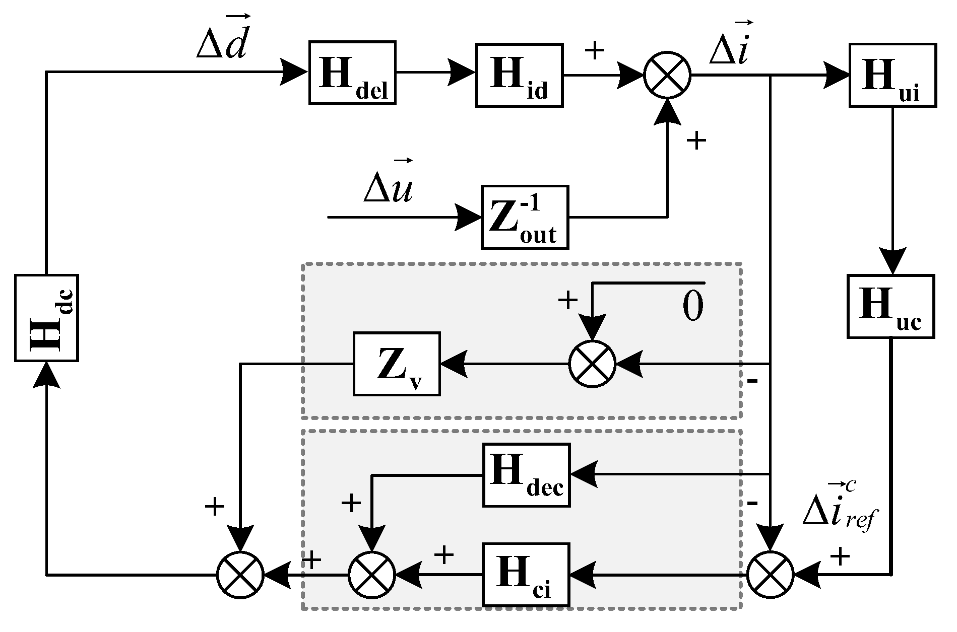
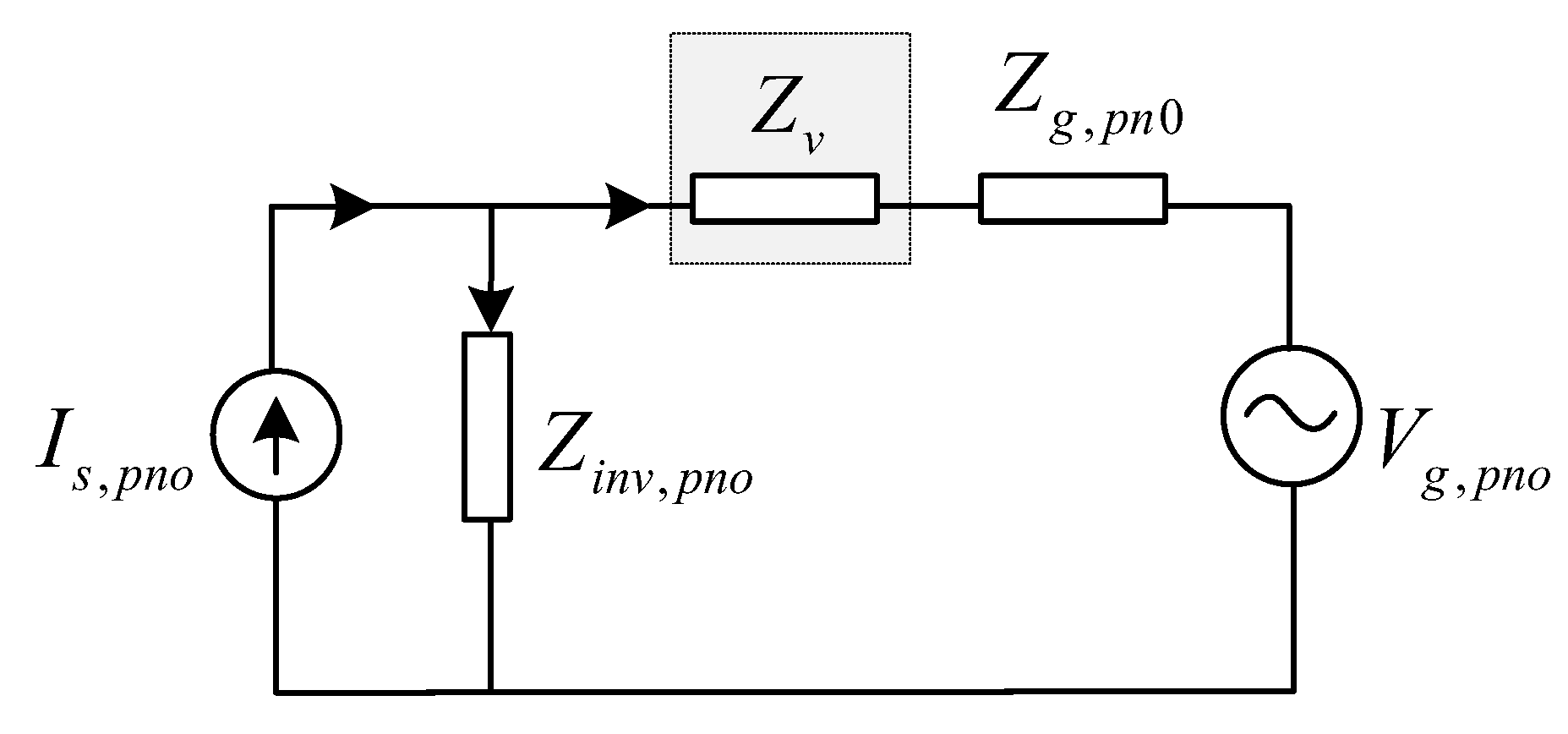
4.1. Research on Impedance Remodeling Strategy Based on Improved Damping Controller
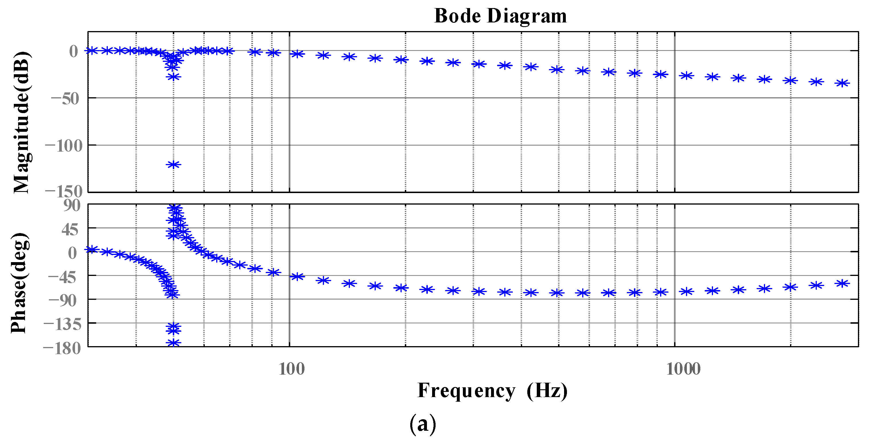
In the three-phase three-wire inverter system, references [23,24] used the grid voltage feedforward strategy to improve the harmonic suppression ability of the inverter. This method is equivalent to an additional parallel admittance on the output admittance of the original inverter. At this time, the equivalent admittance of the inverter output becomes . The blue vector in Figure 6 shows the grid voltage feedforward admittance remodeling process. It can be seen that after the introduction of voltage feedforward, the output admittance amplitude and phase of the three-phase three-wire inverter are reduced, the harmonic suppression ability of the inverter is enhanced, and the resonant damping effect of the control loop is improved.
Figure 6.
Remolded admittance vector diagram of three-phase three-wire and three-phase four-wire inverters after introducing voltage feedforward control.
When the voltage feedforward strategy is adopted in the three-phase four-phase inverter, the remodeling process is shown as the green vector in Figure 6, which is the output admittance of the inverter before remodeling and the output admittance of the inverter after remodeling. It can be seen that the output admittance amplitude and phase of the three-phase four-wire inverter increase after the introduction of voltage feedforward, and the harmonic suppression ability of the inverter is greatly reduced. According to the above analysis, the grid voltage feedforward strategy commonly used in the three-phase three-wire inverter system is not suitable for the three-phase four-wire grid-connected inverter.
According to the correlation analysis in Section 2, there are two main reasons for the high-frequency instability of the TFSCI system:
- (1)
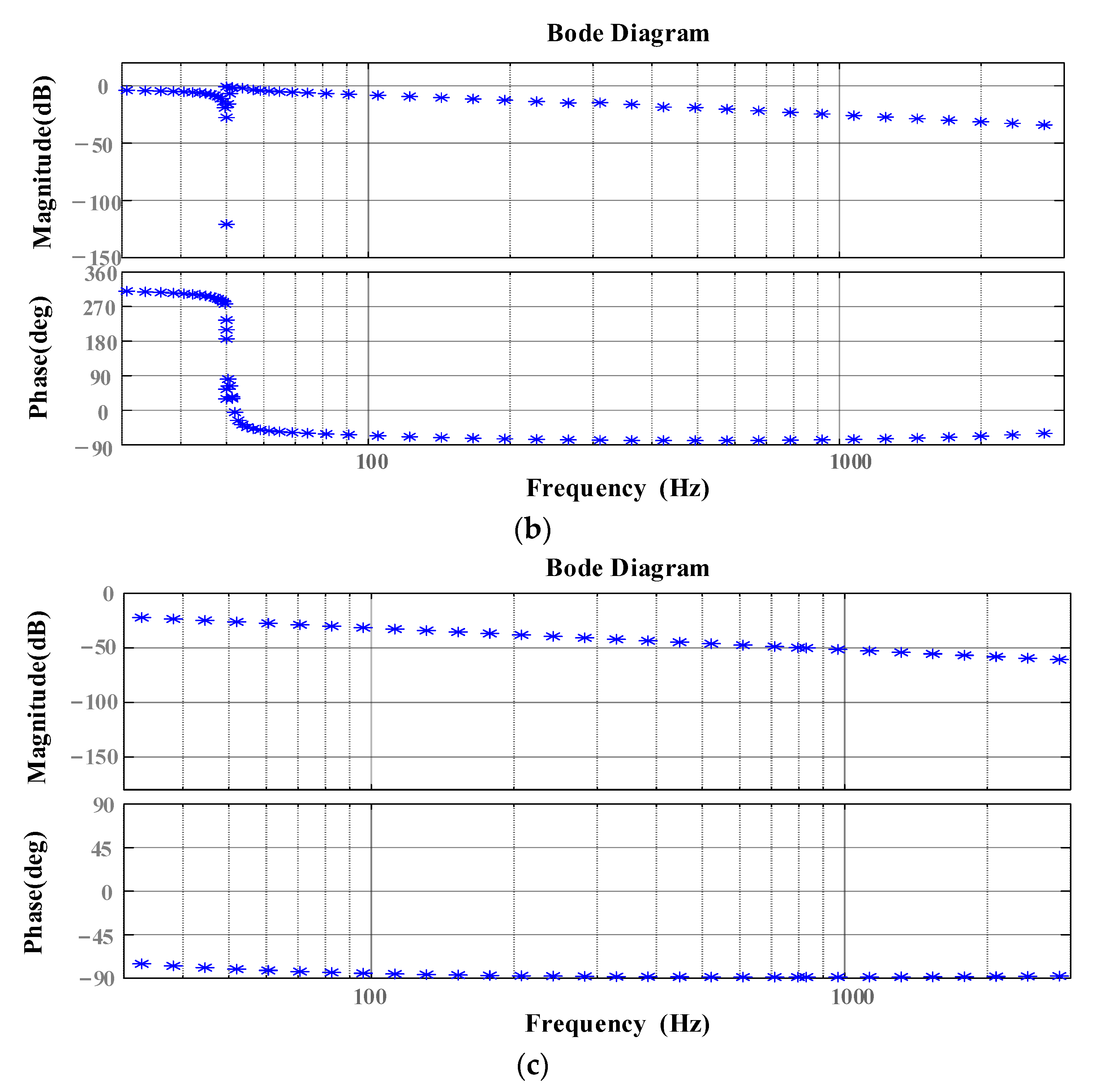
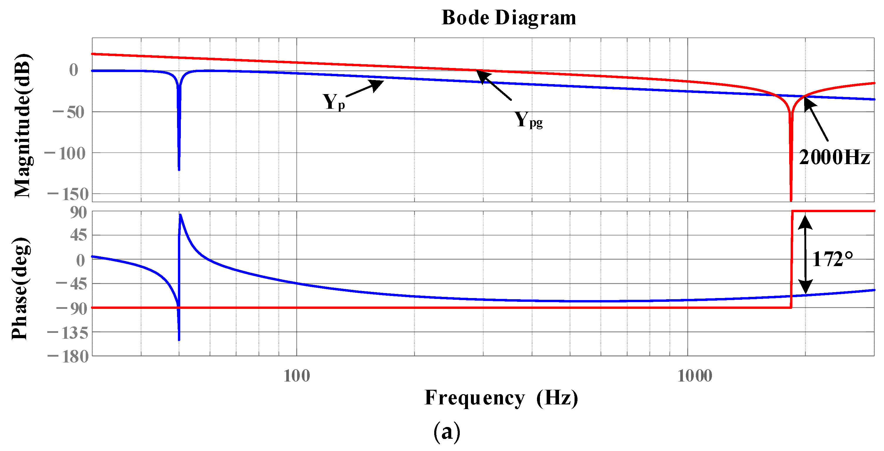
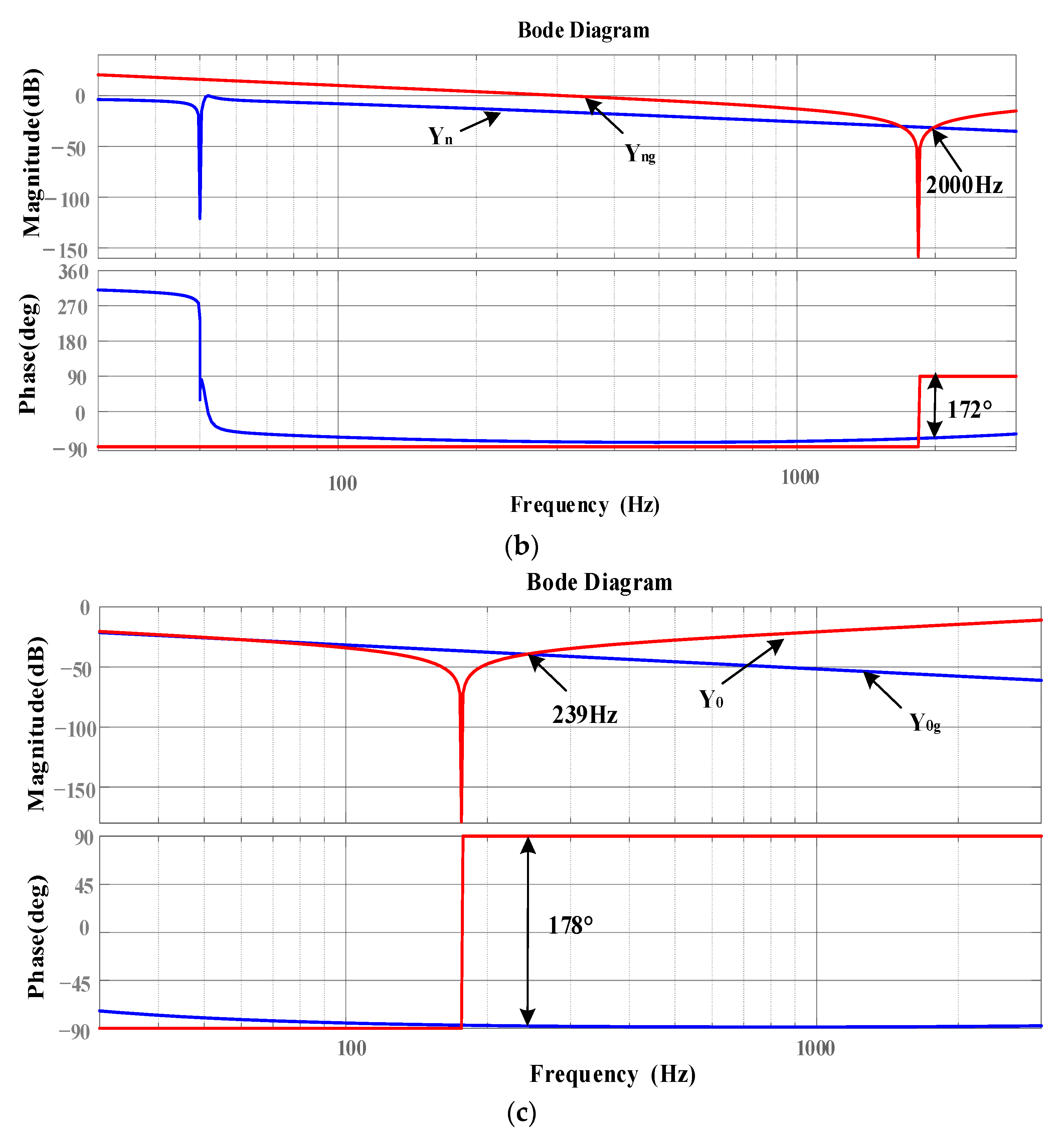
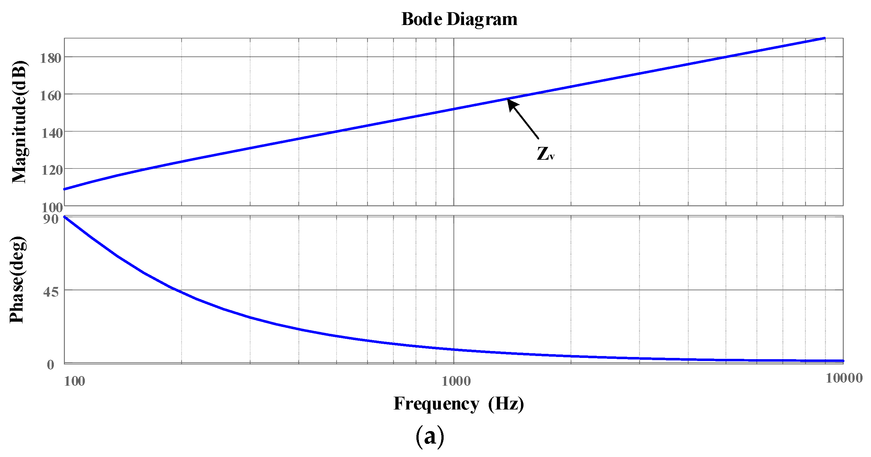
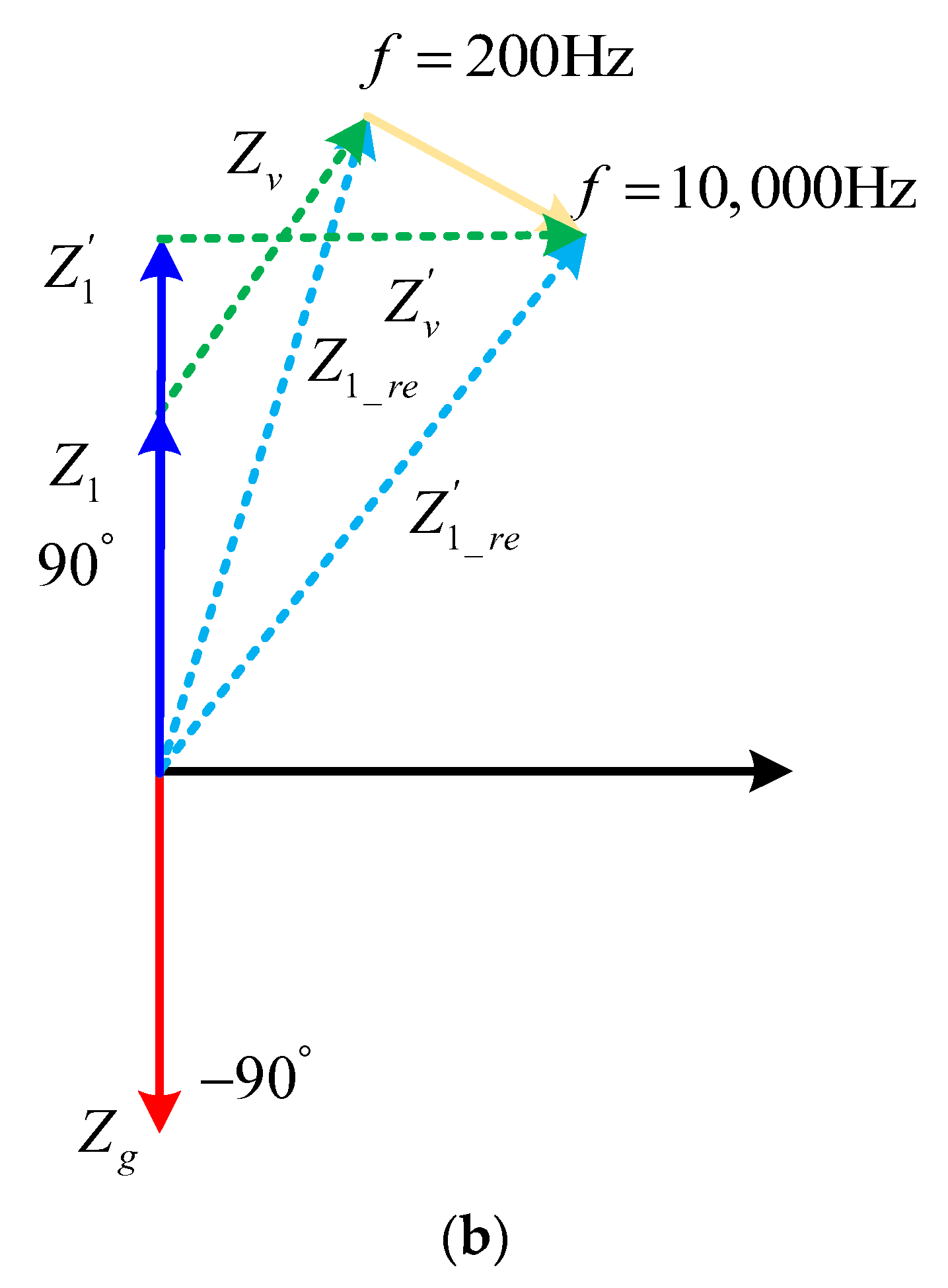
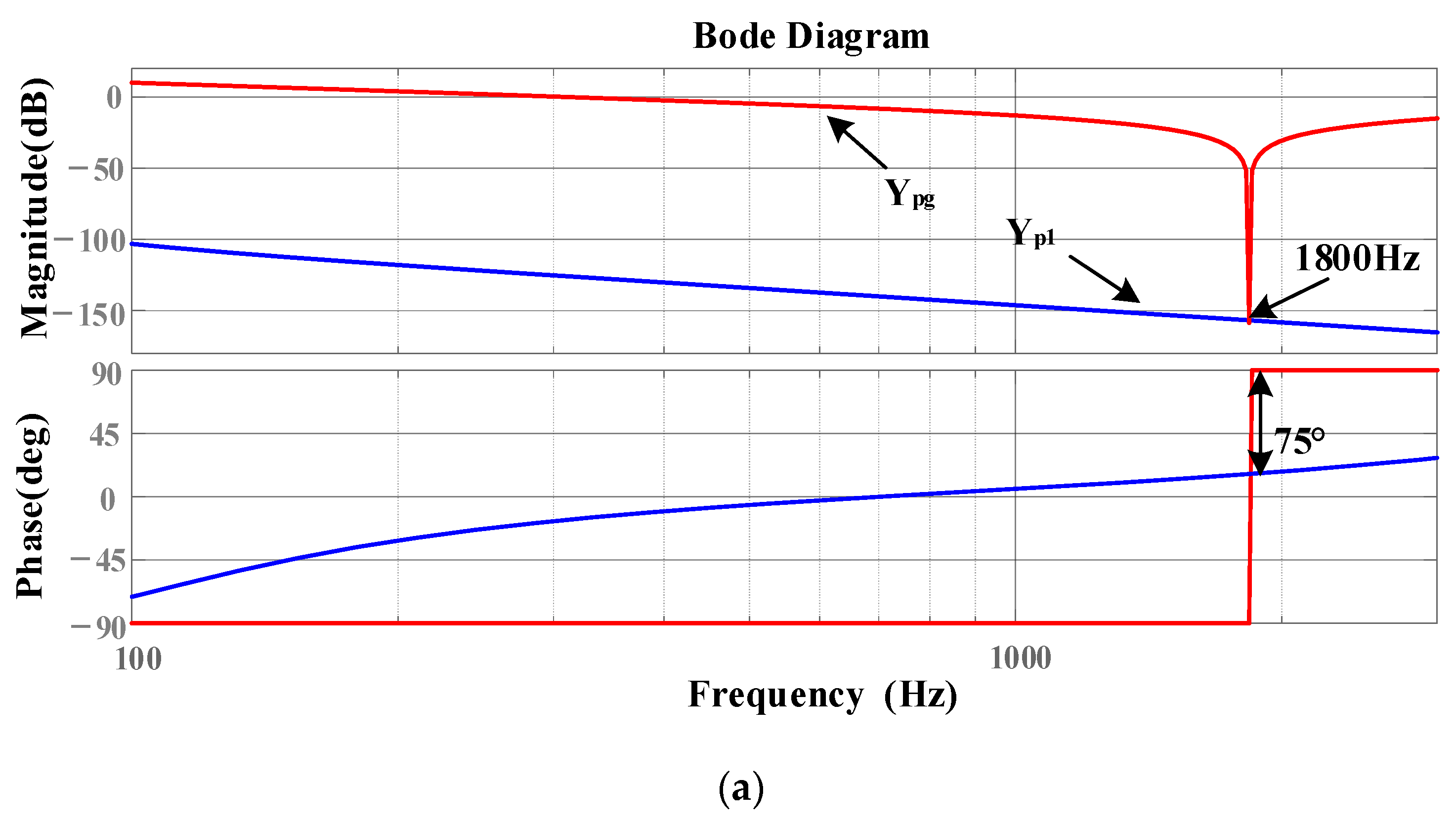
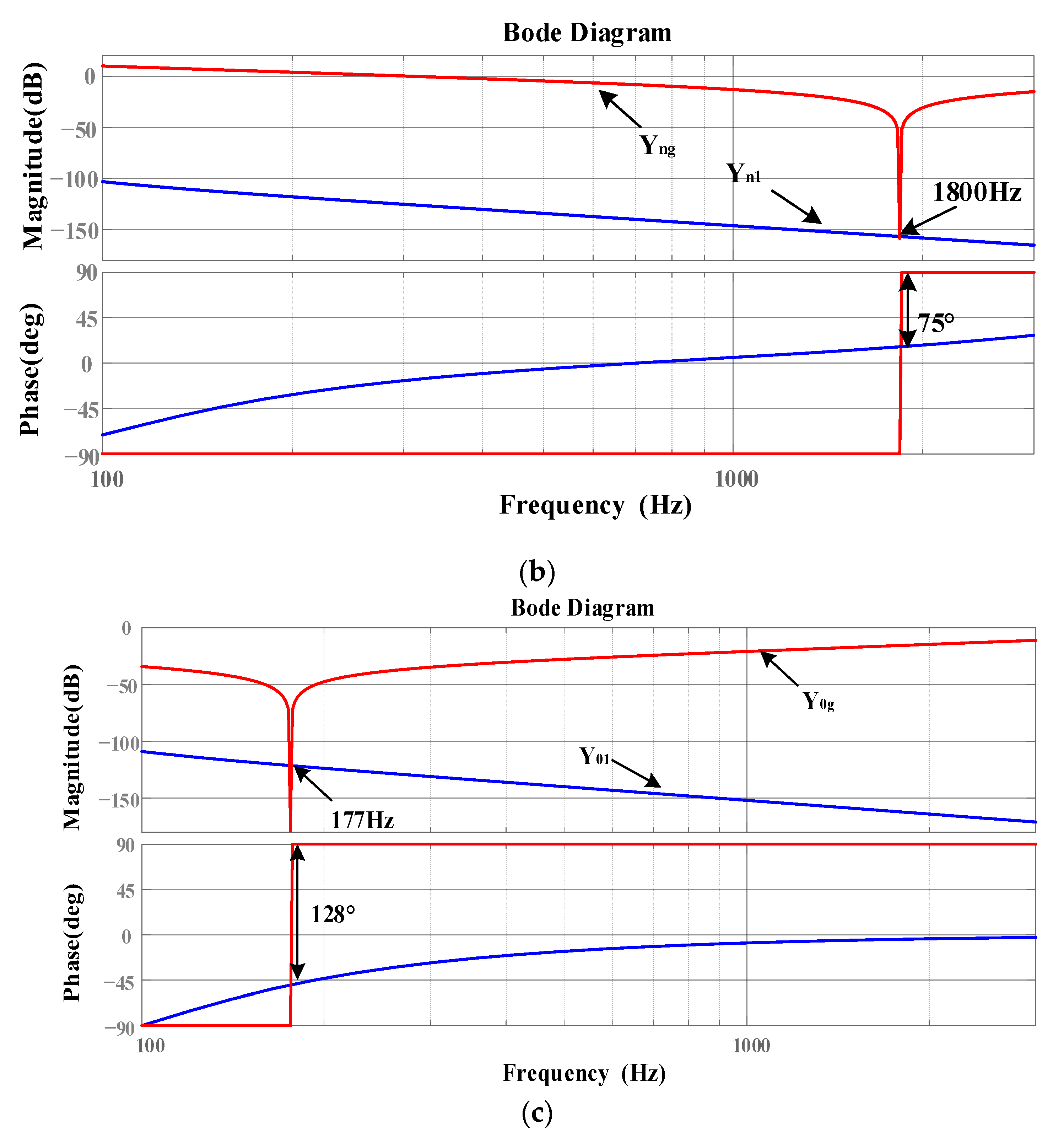
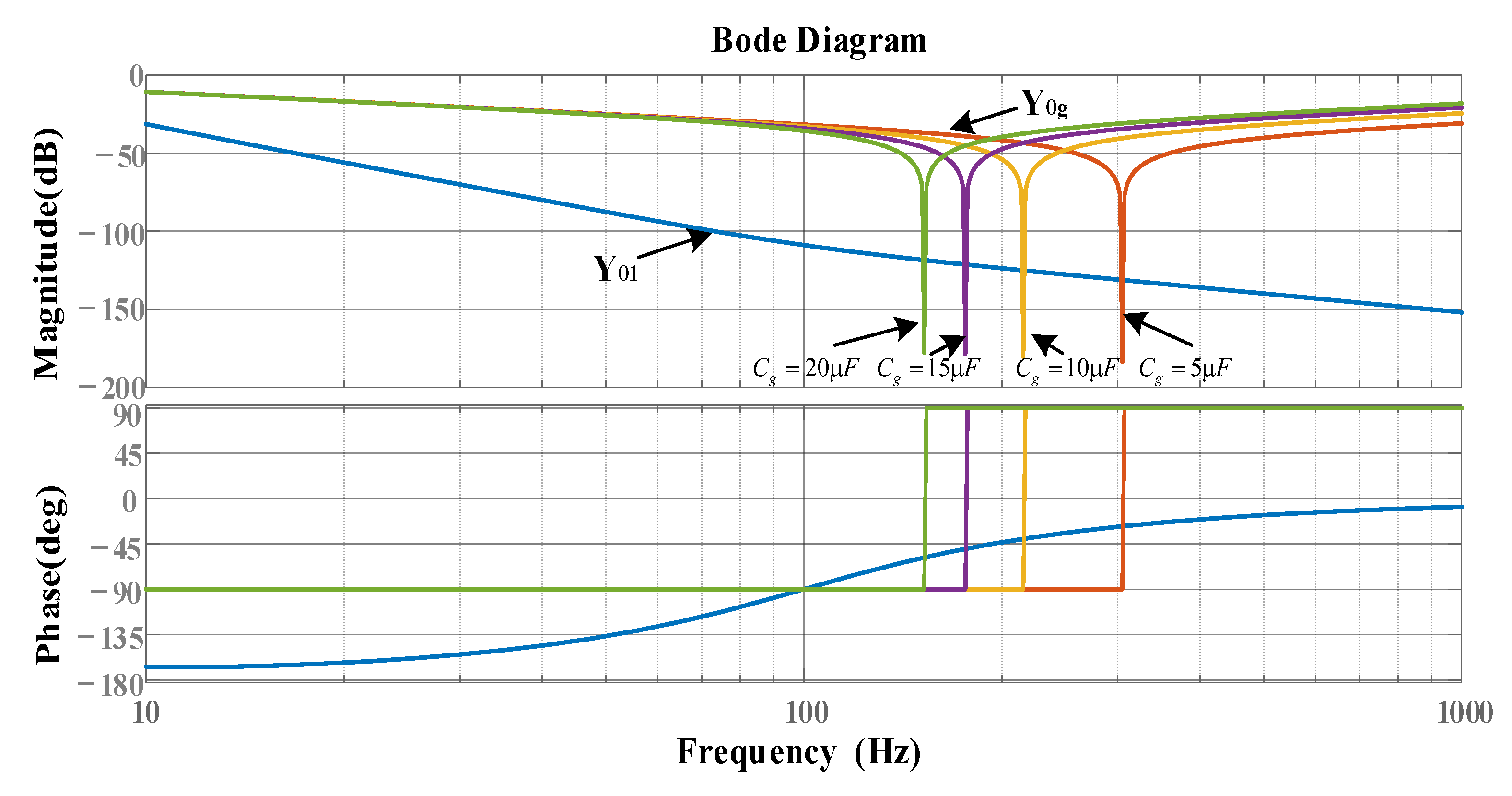
- The amplitude of the inverter system at high frequency is high, so that the intersection frequency of the amplitude-frequency characteristics of the inverter and the grid admittance with shunt capacitor is located on the right side of the grid admittance phase 180° jump, thus introducing high-frequency instability frequency points into the system.
- (2)
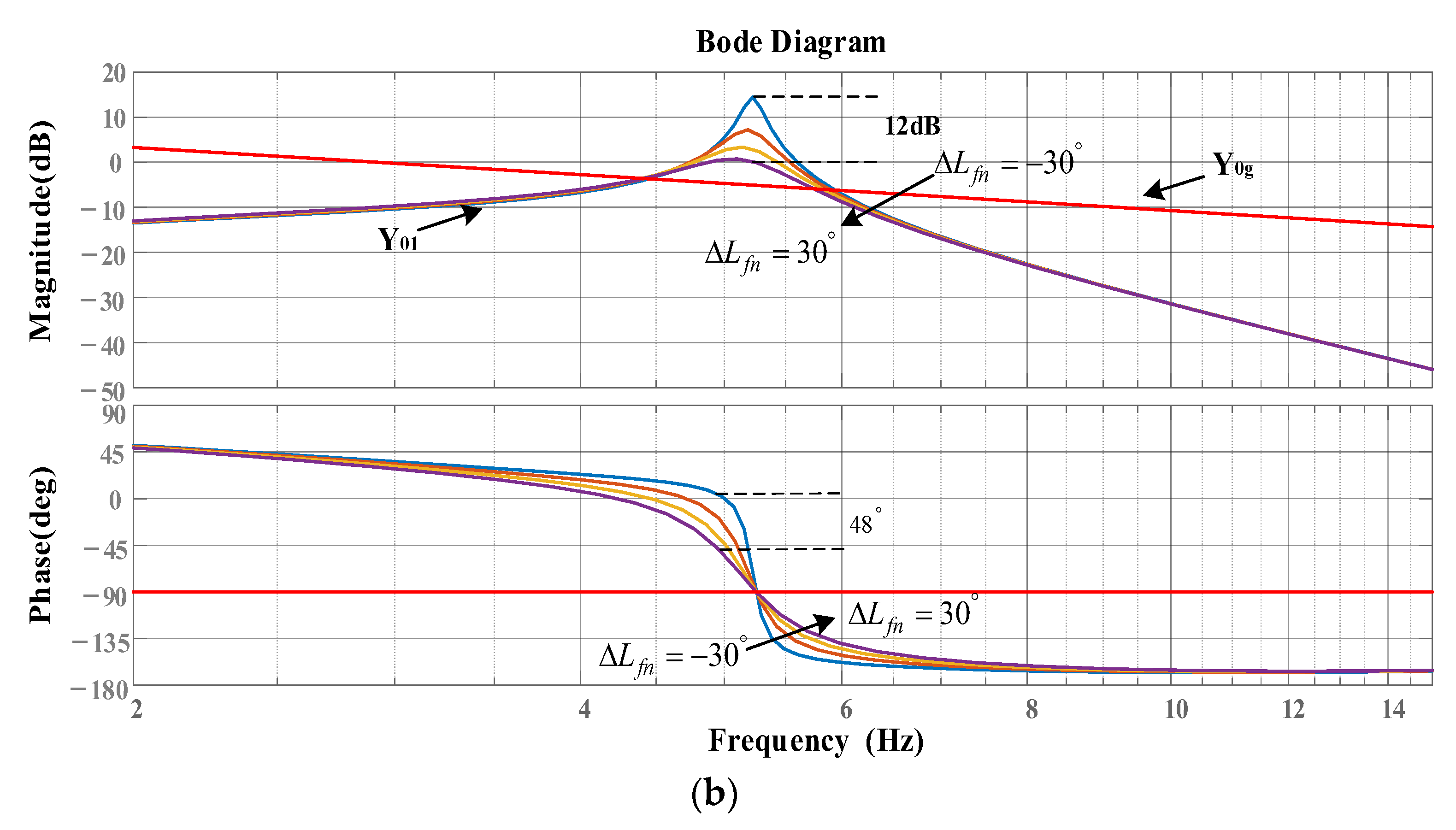
- The admittance phase of the inverter at the frequency band near the intersection of the admittance amplitude-frequency characteristics of the inverter at high frequency and the grid with a shunt capacitor is low. Based on the admittance stability theory, the stability region of the system at high frequency is small.
In order to reduce the risk of high-frequency instability in the TFSCI system, it is necessary to reduce the output admittance amplitude of the inverter system or increase the system phase through the admittance remodeling strategy so as to improve the phase margin of the system in the high-frequency band. Therefore, this paper proposes an oscillation suppression method based on SOGI and a negative third-order differential element for a three-phase, four-wire grid-connected inverter. This method uses the high-frequency phase attenuation characteristics of the SOGI to adjust the output phase of the inverter system in the high-frequency band and uses the negative differential element to increase the order of the inverter system and improve its high-frequency band amplitude frequency characteristics. At the same time, the selection of the SOGI can increase the impedance amplitude difference between the fundamental frequency and the high frequency, thereby reducing the influence of the damping controller on the fundamental frequency control effect of the system. In the damping controller, the order of the negative differentiator component can be flexibly designed. A higher order provides better separation between the system’s fundamental frequency control and high-frequency damping control. However, a higher order also increases the difficulty of system control. Therefore, in this article, a compromise is made by selecting a negative third-order differentiator component. Figure 7 is the small signal model analysis block diagram of the TFSCI after admission remodeling. The improved frequency oscillation damping controller is added to the system’s current controller. The expression is:
where k represents the controller gain, represents the SOGI, the cutoff frequency , , . Among them, can be regarded as variable frequency resistance.
Figure 7.
Block diagram of analysis of admittance model of TFSCI after impedance remodeling.
When the proposed oscillation suppression method based on SOGI and negative third-order differential element is adopted, the closed-loop control block diagram of TFSCI is shown in Figure 8, where Gc(s) represents the transfer function of the PI current controller and kPWM represents the gain of inverter bridge.
Figure 8.
Closed loop control block diagram of TFSCI.
It can be seen from Figure 7 that the output d-q-0 axis reference voltage of the system control link can be expressed as:
The proposed impedance remodeling strategy is equivalent to introducing additional positive, negative and zero sequence additional impedances into the inverter output impedance model. The equivalent model of the three-phase four-wire inverter and the grid interaction system after impedance remodeling is shown in Figure 9.
Figure 9.
Circuit diagram of TFSCI and power grid interaction system after impedance remodeling.
After adopting the proposed control strategy, the positive, negative and zero sequence admittance of the inverter can be expressed as follows:
Figure 10a is the Bode diagram of . It is observed that in the frequency range of 100 Hz~10,000 Hz, the amplitude of increases linearly with the frequency and the phase tends to 0, that is, gradually shows resistance characteristics with the increase of frequency. Figure 10b shows the impedance vector diagram of the inverter after remodeling. It can be seen that when the frequency increases, the impedance phase of the inverter system gradually decreases and the amplitude increases from to . It can be seen that the introduction of a high-frequency oscillation controller improves the system’s harmonic suppression ability and phase margin, and the proposed control strategy can effectively reduce the high-frequency instability risk of TFSCI.

Figure 10.
Admittance remodeling process of TFSCI. (a) The Bode diagram of . (b) Impedance vector diagram after remodeling.
Figure 11 is the Bode diagram of the reshaped TFSCI and the positive, negative, and zero-sequence admittances of the power grid. It can be seen from the figure that the grid admittance and the positive, negative, and zero sequence admittance amplitudes of the inverter are at 1800 Hz, 1800 Hz, and 177 Hz, respectively. Based on the admittance stability theory, the positive, negative, and zero-sequence stability margins of the inverter system are 105°, 105°, and 52°, respectively. Through the above analysis, it can be seen that the admittance amplitude of the reshaped TFSCI decreases and the phase increases, which verifies the effectiveness of the proposed three-phase, four-wire inverter high-frequency oscillation suppression strategy.

Figure 11.
The admittance bode diagram of TFSCI and power grid with parallel compensation capacitors after remodeling. (a) positive sequence. (b) negative sequence. (c) zero sequence.
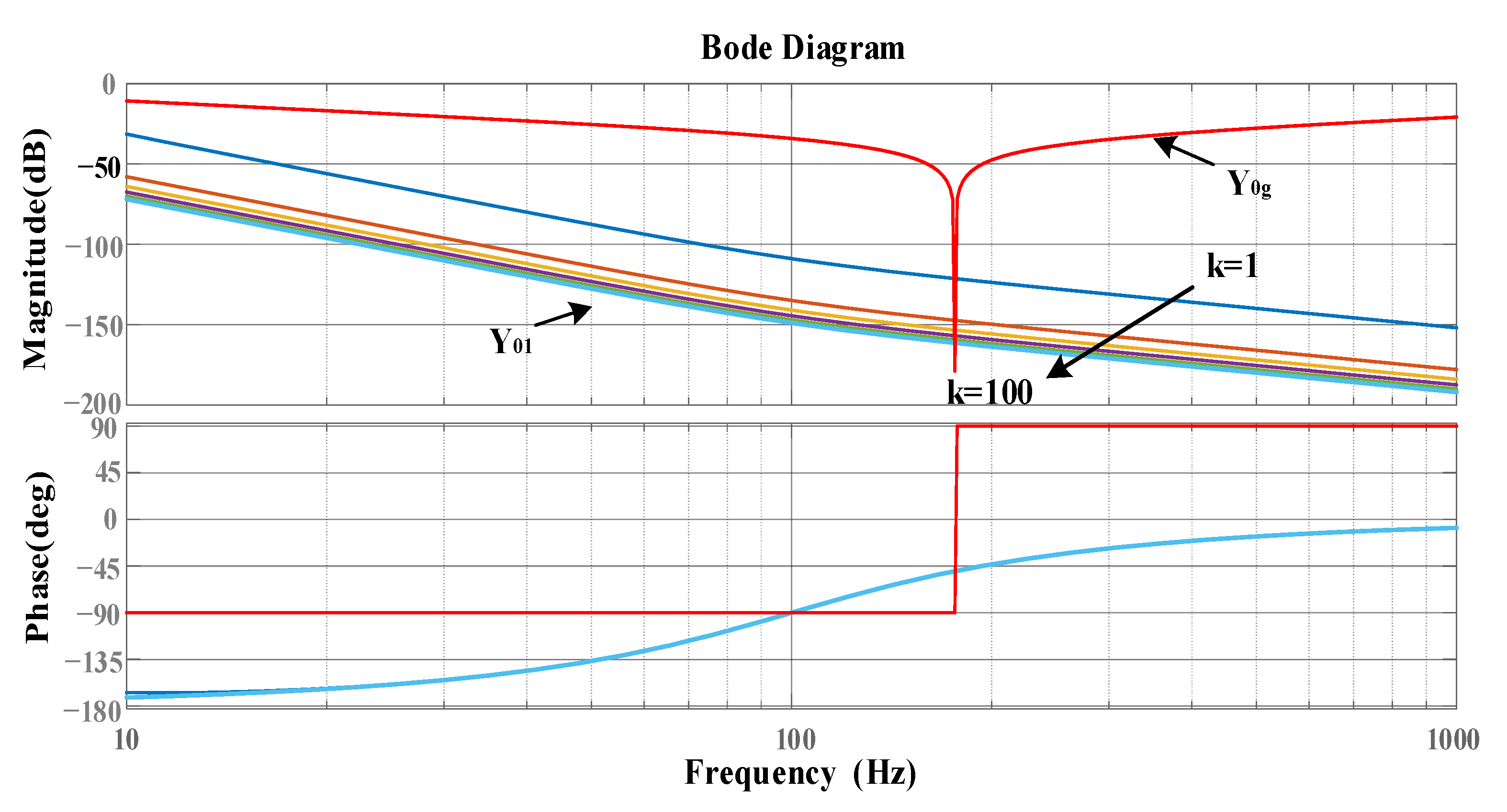
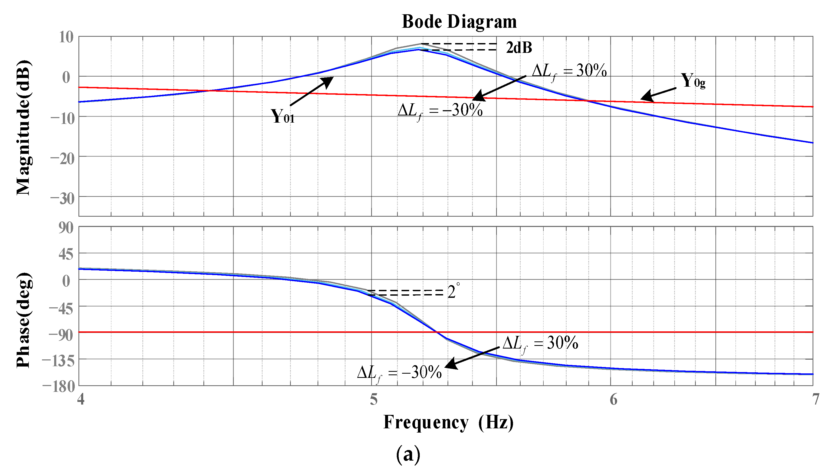
4.2. Parameter Analysis of High Frequency Oscillation Controller
In order to verify the adaptability of the proposed control strategy when the parameters change and determine the range of relevant control parameters, this section will take the zero-sequence inverter system as an example to discuss the inverter admittance remodeling effect under different control parameters.
Firstly, the influence of high-frequency controller gain k on the effect of inverter impedance remodeling is discussed. Figure 12 shows the zero-sequence admittance and grid admittance Bode diagram of the TFSCI when k changes from 1 to 100. It can be seen that the amplitude of the zero-sequence admittance of the inverter output will decrease with the increase of the gain k after using the proposed control strategy. The phase is basically unchanged, and the system has a large stability margin when k changes. In order to ensure the fundamental frequency control performance and sufficient phase margin of the system, the high-frequency controller gain k = 5 is selected in this paper.
Figure 12.
Bode diagram of zero sequence admittance and grid admittance of TFSCI when k changes from 1 to 100.
Secondly, the influence of filter inductance deviation on the effect of inverter impedance remodeling is discussed. Figure 13 shows the inverter output admittance Bode diagram when the filter inductance deviation and the midline inductance deviation change in the interval. It can be seen from the observation that the filter inductance deviation and the midline inductance deviation only affect the output admittance characteristics of the inverter at low frequencies and have no effect on the inverter admittance remodeling effect at high frequencies, which proves that the proposed oscillation suppression strategy still has strong adaptability when the inductance parameters change.

Figure 13.
Bode diagram of inverter zero-sequence remodeling admittance when filter inductance deviation and midline inductance deviation change in range. (a) filter inductance. (b) neutral inductor.
Finally, the influence of capacitor offset on the impedance remodeling effect of the inverter is discussed. Figure 14 shows the inverter output admittance Bode diagram when the shunt capacitor changes. It can be seen that the proposed admittance reshaping strategy can still ensure that the three-phase four-wire inverter system has a high phase margin when the shunt capacitor changes, and the risk of high-frequency instability of the system is greatly reduced, which proves that the improved frequency oscillation suppression strategy still has strong adaptability when the shunt capacitor changes.
Figure 14.
Bode diagram of inverter zero-sequence remodeling admittance when parallel compensation capacitors change.
5. Simulation and Experimental
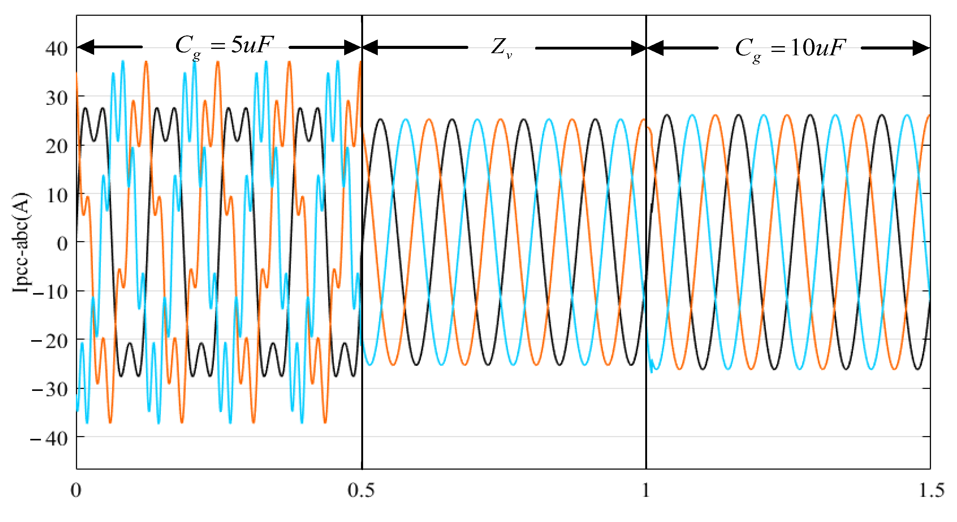
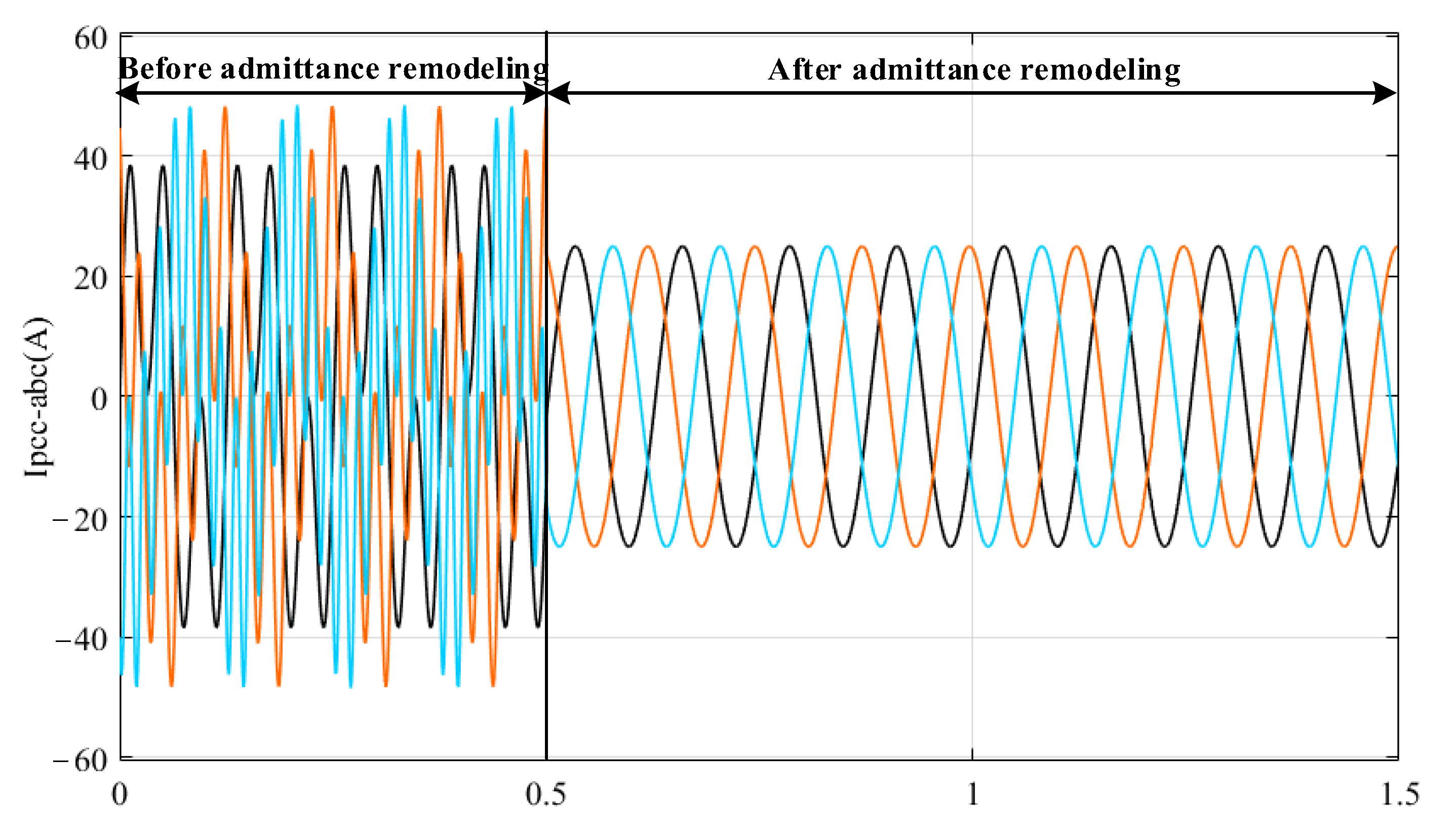
5.1. Simulation Verification
In this paper, MATLAB/SIMULINK simulation software is used to build the interaction model between the TFSCI and the grid with shunt capacitor. Table 1 gives the relevant parameters of the TFSCI.
Table 1.
Relevant parameters of TFSCI.
Figure 15a shows the output current waveform of the inverter without a shunt capacitor under a weak grid. It can be seen that the inverter can operate stably. Figure 15b shows the output current waveform of the inverter after adding the shunt capacitor to the grid. At this time, the inverter system is unstable, which verifies that the addition of the shunt capacitor to the three-phase, four-wire inverter under the weak grid will cause the system to oscillate.

Figure 15.
Simulation waveform of inverter grid-connected current with or without parallel compensation capacitors. (a) No shunt capacitor. (b) Adding the shunt capacitor.
Figure 16 is the output current waveform of the system when the shunt capacitor of the TFSCI changes. Before 0.5 s, the parallel capacitor of the grid is 5 μF, and the THD of the current at the PCC point is 17.14 %, and the power quality of the system output current is poor. The proposed admittance remodeling strategy is added at 0.5 s. It is observed that the high-frequency oscillation phenomenon in the inverter system is suppressed within 0.004 s, and the system can operate stably. At this time, the current THD at the PCC point is 1.71 %. In order to verify the adaptability of the proposed oscillation suppression strategy when the shunt capacitor changes, the shunt capacitor is increased to 10 μF at 1 s. The observation shows that the inverter system can still operate stably, which verifies that the proposed control strategy has strong adaptability to the change of capacitor compensation degree.
Figure 16.
Simulation waveform of inverter grid-connected current when the parallel compensation capacitors change.
Figure 17 shows the output grid-connected current waveform of the TFSCI after the parallel capacitor is added and the 5th and 7th harmonic voltages of 0.1 pu are injected into the grid voltage. At 0.5 s, after adopting the proposed admittance remodeling strategy, it is observed that the output current power quality of the system is better at this time, and the system can operate stably. The simulation results show that the proposed oscillation suppression strategy still has strong adaptability under harmonic grid.
Figure 17.
Simulation waveform of inverter grid-connected current before and after admittance remodeling when harmonics are injected into the grid.
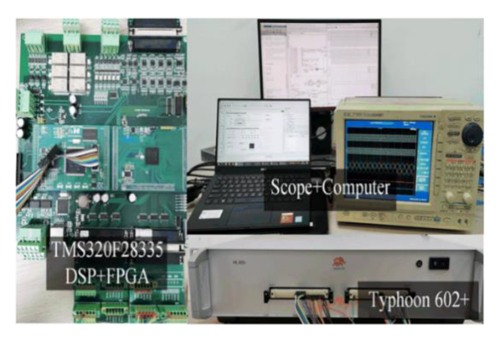
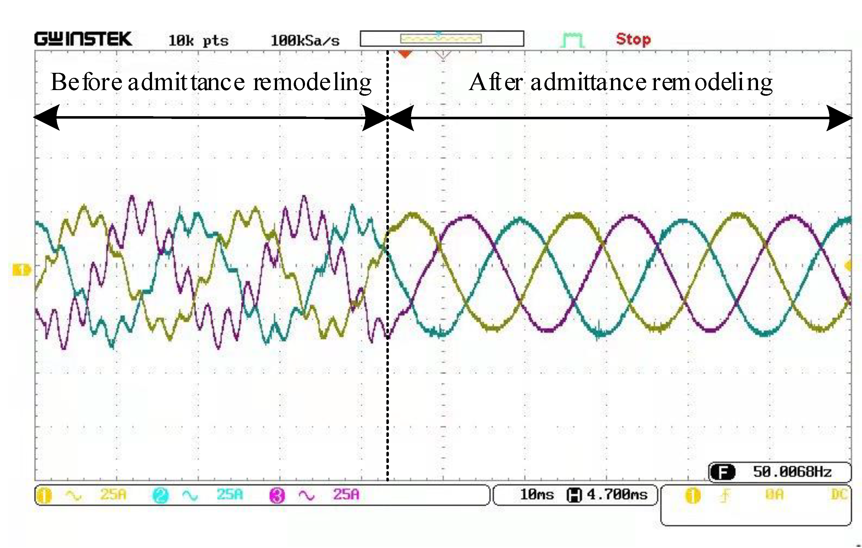
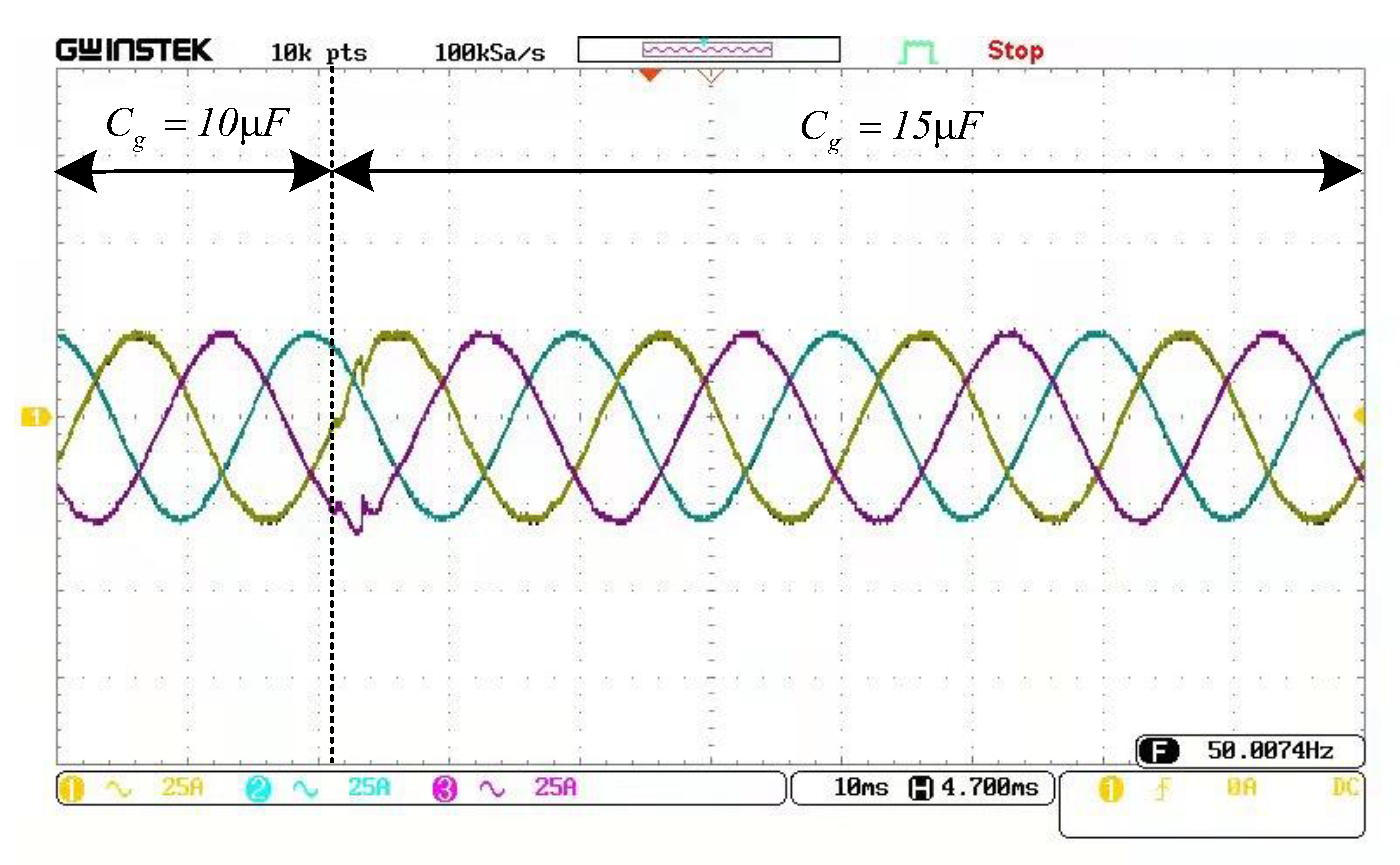
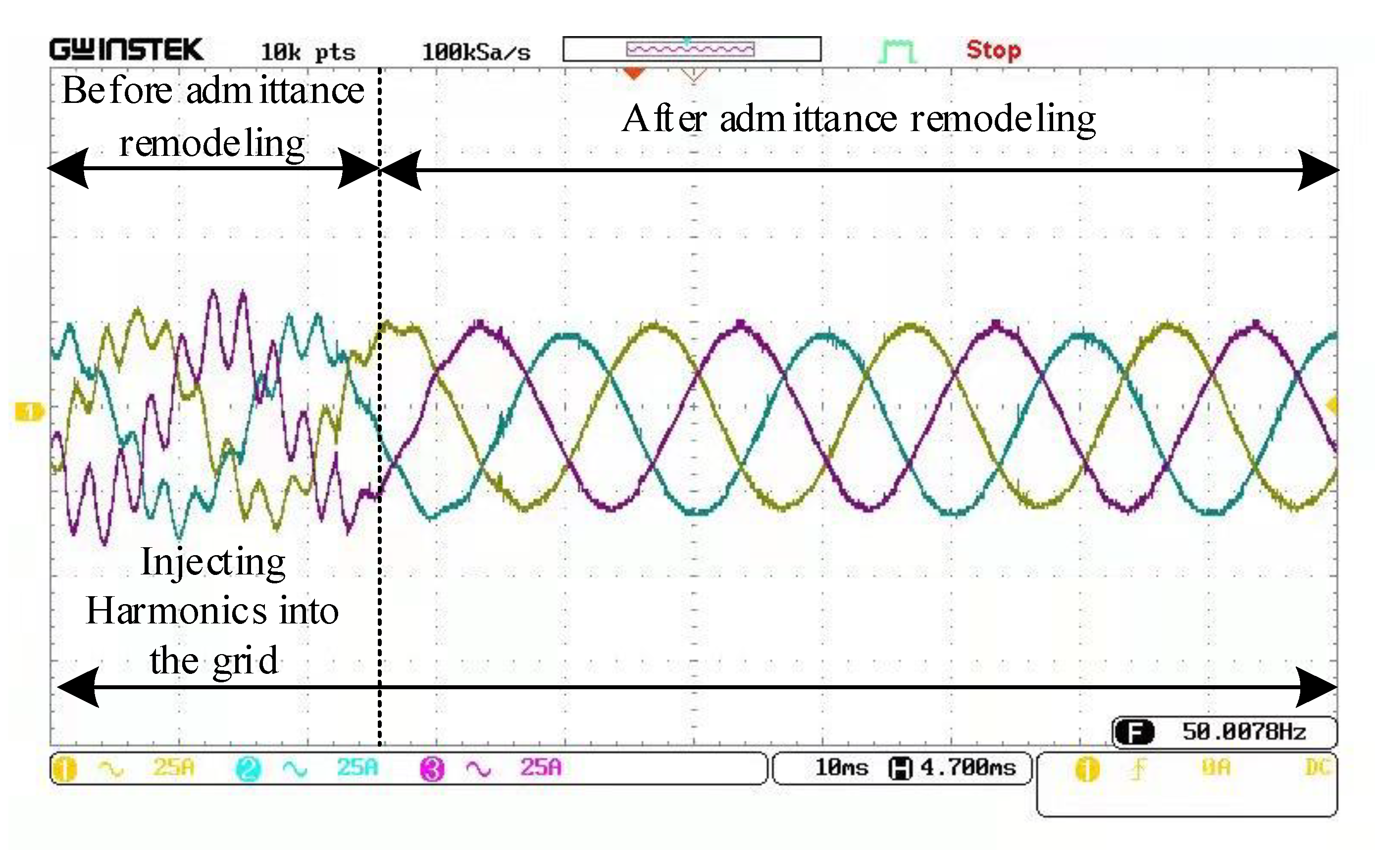
5.2. Experimental Verification
In order to verify the effectiveness of the oscillation suppression strategy proposed in this paper, a TFSCI experimental platform based on in-loop control (CHIL) is built as shown in Figure 18, and the time step is set to 1 μs.
Figure 18.
Experimental platform of TFSCI based on in-loop control (CHIL).
Figure 19 is the experimental waveform of the grid-connected current of the inverter before and after adding a parallel compensation capacitor. From the diagram, it can be seen that the inverter can operate stably when the grid-side equivalent inductance Lg = 1 mH in the weak grid. When a 5 μF parallel compensation capacitor is added to the grid side, the system gradually loses stability, and the power quality of the inverter output current continues to deteriorate. The results show that the addition of the grid-side parallel compensation capacitor destroys the original stable state of the inverter.
Figure 19.
Experimental waveform of inverter grid-connected current before and after adding parallel compensation capacitors.
Figure 20 is the experimental waveform of grid-connected current before and after impedance remodeling. It can be seen from the figure that the system is unstable when the inverter is connected to the grid with a shunt capacitor. When the impedance reshaping strategy designed in this paper is adopted, the system can quickly restore stability, showing good dynamic response and steady-state operation performance. The experimental results verify that the impedance reshaping strategy designed in this paper can effectively suppress the oscillation phenomenon of the TFSCI.
Figure 20.
Experimental waveform of inverter grid-connected current before and after admittance remodeling.
Figure 21 is the experimental waveform of the grid-connected current of the inverter when the capacitance changes after the impedance remodeling strategy is adopted. From the diagram, it can be seen that the system can still maintain stable operation when the grid-side shunt capacitor changes from 10 μF to 15 μF, and the inverter system can complete the transition within 0.005 s after capacitor switching, which verifies that the impedance remodeling strategy designed in this paper has strong adaptability to the change of shunt capacitor.
Figure 21.
Experimental waveform of inverter grid-connected current when parallel compensation capacitors are changed after admittance remodeling.
Figure 22 is the grid-connected current experimental waveform of the inverter before and after the impedance remodeling after the grid is injected with harmonics, in which the grid side is set to inject 5 and 7 harmonics of 0.1 pu respectively. It can be seen from the figure that when the harmonic content of the grid is high, the proposed impedance reshaping strategy can still make the inverter operate stably, and the power quality of the inverter output current is high, which verifies that the impedance reshaping strategy designed in this paper can still effectively suppress the inverter oscillation phenomenon under the harmonic grid.
Figure 22.
Experimental waveform of inverter grid-connected current before and after admittance remodeling when harmonics are injected into the grid.
6. Conclusions
In this paper, the admittance model of TFSCI was derived based on the small signal correlation model of grid voltage, inverter current, and duty cycle variable disturbance. The positive, negative, and zero-sequence stability of the inverter system under a weak grid and its high-frequency oscillation suppression strategy are studied. When the grid contains shunt capacitors, the stability margin of the three-phase, four-wire grid-connected inverter is low in the high-frequency band, and the system has the risk of high-frequency oscillation instability. The admittance remodeling strategy based on a negative third-order differential element and SOGI can correct the output admittance amplitude and phase of a high-frequency three-phase four-wire inverter so as to ensure that the inverter system still has sufficient stability margin at high frequency. The proposed control strategy can effectively suppress the high-frequency oscillation of the system when the main parameters of the system change, which greatly improves the stability control parameter domain of the three-phase, four-wire inverter. The experimental results verify that the proposed inverter oscillation suppression strategy is correct and feasible. Finally, it is worth noting that the adaptive quantitative design method of controller parameters considering the stability of the inverter and the adaptability of grid-side parameters under weak grids will be the future research direction.
Author Contributions
Conceptualization, G.F. and Y.X.; methodology, Z.Y.; software, G.F.; validation, Y.X., Z.Y. and H.N.; formal analysis, G.F.; investigation, G.F.; resources, Z.Y.; data curation, Y.X.; writing—original draft preparation, G.F.; writing—review and editing, Y.X.; visualization, Z.Y.; supervision, H.N.; project administration, G.F.; funding acquisition, Y.J. All authors have read and agreed to the published version of the manuscript.
Funding
This research was funded by the National Natural Science Foundation of China (Grant No. 51507183 and No. 51877212).
Data Availability Statement
The data that support the findings of this study are available from the corresponding author upon reasonable request.
Conflicts of Interest
The authors declare no conflict of interest.
Appendix A
In this appendix, the positive, negative and zero sequence admittance models of TFSCI are derived from model (2). From Equation (2), the small signal model of the inverter system in the d-q-0 coordinate system is shown in Figure A1, which is based on the static operating point of the inverter. where X represents the steady-state value of x, and represents the small signal perturbation corresponding to x.
Figure A1.
Small signal model of inverter system in d-q-0 coordinate system. (a) d-axis small signal equivalent model. (b) q-axis small signal equivalent model. (c) 0 axis small signal equivalent model.
It can be seen from Figure A1 that, assuming , , the transfer function matrix from the disturbance current to the voltage response in the system model can be expressed as:
Similarly, assuming in Figure A1, the transfer function matrix from the duty cycle to the corresponding current response in the system model can be expressed as:
Based on the above analysis, the small signal model block diagram of the TFSCI is shown in Figure A2. Among them, the transfer matrix represents the inverter control delay link, and its expression is:
In the formula, the delay time is represented.
Figure A2.
Block diagram of small signal model of TFSCI.
The transfer matrix represents the d-q axis decoupling link transfer matrix in the current controller, and its expression is:
The transfer matrix represents the PI regulator in the current controller, and its expressions are:
In the formula, and denotes the proportional coefficient and integral coefficient of d-q axis current controller respectively, and denotes the proportional coefficient and integral coefficient of 0 axis current controller respectively.
The expression of the DC voltage transfer matrix is:
According to Equation (5), the transfer matrix of current disturbance to DC voltage disturbance in d-q-0 coordinate system can be expressed as:
It can be seen from Figure 1 that in the DC voltage balance PI controller, the transfer matrix expression from the DC side disturbance voltage to the reference disturbance current can be expressed as:
In the formula, and represent the proportional coefficient and integral coefficient of the PI controller that balances the DC voltage, respectively.
According to the analysis of Figure A2, the admittance of TFSCI from to can be expressed as:
In the case of three-phase symmetry, the admittance matrix in the d-q-0 coordinate system can be equivalently converted into positive, negative and zero sequence admittance matrices . The conversion relationship is:
In the formula, the expression of the transformation matrix is:
Because the instability excitation frequency is high when the inverter oscillates at high frequency, |s| much larger than 1, that is, 1/s can be approximated as 0. The expressions of positive, negative and zero sequence admittance of TFSCI can be obtained by sorting out Equation (A10):
References
- Tu, C.; Gao, J.; Zhao, J.; Guo, Q. Analysis and design of grid-connected inverter impedance remodeling with fixed stability margin in weak grid. Trans. China Electrotech. Soc. 2020, 35, 1327–1335. [Google Scholar]
- Zhou, X.; Chen, S.; Lu, Z.; Huang, Y.; Ma, S.; Zhao, Q. Technology features of the new generation power system in China. Proc. CSEE 2018, 38, 1893–1904. [Google Scholar]
- Zhou, L.; Luo, A.; Chen, Y.; Chen, Z.Y. A single-phase grid-connected power control and active damping optimization strategy with LCL filter. Trans. China Electrotech. Soc. 2016, 31, 144–154. [Google Scholar]
- Xie, Z.; Wu, W.; Chen, Y.; Cao, S.; Xu, Y. Sequence-Admittance Measurement Method of Grid-Connected Inverter With Its Control System Disturbance. IEEE Trans. Ind. Electron. 2023, 70, 8598–8602. [Google Scholar] [CrossRef]
- Sun, H.; Zhai, H.; Wu, X. Research and application of multi-energy coordinated control of generation, network, load and storage. Trans. China Electrotech. Soc. 2021, 36, 3264–3271. [Google Scholar]
- Wu, X.; Wang, J.; Liu, J.; Zhao, Y.; Liu, F.; Zhao, Z.; Zhang, X. Three-phase four-wire power supply method for three-phase three-leg inverter using low-voltage neutral point regulator. Power Syst. Technol. 2019, 43, 4209–4217. [Google Scholar] [CrossRef]
- Zhang, Y.; Chen, X.; Wang, Y.; Gong, C. Impedance-phased dynamic control method of grid-connected inverters under weak grid condition. Trans. China Electrotech. Soc. 2017, 32, 97–106. [Google Scholar]
- Xu, H.; Wu, H.; Li, Z. Several key issues on stability study of DFIG-based wind turbines with negative sequence control during low short-circuit ratio power grids. Trans. China Electrotech. Soc. 2021, 36, 4688–4702. [Google Scholar]
- Nian, H.; Pang, B.; Xu, G. Reshaping strategy of wide frequency impedance for DFIG system to suppress high frequency resonance under parallel compensation grid. Autom. Electr. Power Syst. 2018, 42, 48–56. [Google Scholar]
- Muhammad, T.; Khan, A.U.; Abid, Y.; Khan, M.H.; Ullah, N.; Blazek, V.; Prokop, L.; Misák, S. An Adaptive Hybrid Control of Reduced Switch Multilevel Grid Connected Inverter for Weak Grid Applications. IEEE Access 2023, 11, 28103–28118. [Google Scholar] [CrossRef]
- Xie, Z.; Chen, Y.; Wu, W. A global high-frequency oscillation suppression method for multi-inverter grid-connected system in weak grid. Trans. China Electrotech. Soc. 2020, 35, 885–895. [Google Scholar]
- Huang, Y.; Yuan, X.; Hu, J.; Zhou, P.; Wang, D. DC-Bus voltage control stability affected by AC-bus voltage control in VSCs connected to weak AC grids. IEEE J. Emerg. Sel. Top. Power Electron. 2016, 4, 445–457. [Google Scholar] [CrossRef]
- Xiong, L.; Zhou, F.; Wang, F.; Liu, X.; Chen, Y.; Zhu, M.; Yi, H. Static synchronous generator model: A new perspective to investigate dynamic characteristics and stability issues of grid-tied PWM inverter. IEEE Trans. Power Electron. 2016, 31, 6264–6280. [Google Scholar] [CrossRef]
- Huang, Y.; Yuan, X.; Hu, J.; Zhou, P. Modeling of VSC connected to weak grid for stability analysis of DC-link voltage control. IEEE J. Emerg. Sel. Top. Power Electron. 2015, 3, 1193–1204. [Google Scholar] [CrossRef]
- Wang, C.; Sun, J.; Gong, J.; Zha, X. Mechanism and damping strategy of interactive instability between grid-connected inverter and grid impedance. Trans. China Electrotech. Soc. 2020, 35, 503–511. [Google Scholar]
- Yang, D.; Ruan, X.; Wu, H. Impedance shaping of the grid-connected inverter with LCL filter to improve its adaptability to the weak grid condition. IEEE Trans. Power Electron. 2014, 29, 5795–5805. [Google Scholar] [CrossRef]
- Ji, Y.; Wang, D.; Wu, H. The active damping method for improving the stability of DC microgrid. Trans. China Electrotech. Soc. 2018, 33, 370–379. [Google Scholar]
- Liu, J.; Chen, Y.; Wu, W. Sequence impedance modeling and high-frequency oscillation suppression method for Island microgrid. Trans. China Electrotech. Soc. 2020, 35, 1538–1552. [Google Scholar]
- Liu, H.; Xie, X.; Li, Y.; Liu, H.; Hu, Y. Mitigation of SSR by embedding subsynchronous notch filters into DFIG converter controllers. IET Gener. Transm. Distrib. 2017, 11, 2888–2896. [Google Scholar] [CrossRef]
- Nian, H.; Hu, B.; Chen, L.; Xu, Y. Impedance modeling and stability analysis of direct power controlled doubly fed induction generator system without phase-locked loop. Proc. CSEE 2020, 40, 951–962. [Google Scholar]
- Hu, B.; Nian, H.; Li, M.; Xu, Y. Impedance characteristic analysis and reshaping method of DFIG system based on DPC without PLL. IEEE Trans. Ind. Electron. 2021, 68, 9767–9777. [Google Scholar] [CrossRef]
- Du, Y.; Zhang, M.; Yang, X.; Yan, M.; Sun, Q.; Sun, J. Grid-connected inverter stabilization method based on adaptive composite admittance correction. High Volt. Eng. 2022, 48, 2088–2097. [Google Scholar]
- Wang, X.; Qin, K.; Ruan, X.; Pan, D.; He, Y.; Liu, F. A robust grid-voltage feedforward scheme to improve adaptability of grid-connected inverter to weak grid condition. IEEE Trans. Power Electron. 2021, 36, 2384–2395. [Google Scholar] [CrossRef]
- Li, W.; Ruan, X.; Pan, D.; Wang, X. Full-feedforward schemes of grid voltages for a three-phase LCL-type grid-connected inverter. IEEE Trans. Ind. Electron. 2013, 60, 2237–2250. [Google Scholar] [CrossRef]
Disclaimer/Publisher’s Note: The statements, opinions and data contained in all publications are solely those of the individual author(s) and contributor(s) and not of MDPI and/or the editor(s). MDPI and/or the editor(s) disclaim responsibility for any injury to people or property resulting from any ideas, methods, instructions or products referred to in the content. |
© 2023 by the authors. Licensee MDPI, Basel, Switzerland. This article is an open access article distributed under the terms and conditions of the Creative Commons Attribution (CC BY) license (https://creativecommons.org/licenses/by/4.0/).