Article

Autonomous Drone Electronics Amplified with Pontryagin-Based Optimization

1
Sibley School of Mechanical and Aerospace Engineering, Cornell University, Ithaca, NY 14853, USA
2
Department of Mechanical Engineering (SCPD), Stanford University, Stanford, CA 94305, USA
*
Author to whom correspondence should be addressed.
Electronics 2023, 12(11), 2541; https://doi.org/10.3390/electronics12112541
Submission received: 2 April 2023 / Revised: 19 May 2023 / Accepted: 20 May 2023 / Published: 5 June 2023
(This article belongs to the Special Issue Feature Papers in Computer Science & Engineering)

Abstract

:
In the era of electrification and artificial intelligence, direct current motors are widely utilized with numerous innovative adaptive and learning methods. Traditional methods utilize model-based algebraic techniques with system identification, such as recursive least squares, extended least squares, and autoregressive moving averages. The new method known as deterministic artificial intelligence employs physical-based process dynamics to achieve target trajectory tracking. There are two common autonomous trajectory-generation algorithms: sinusoidal function- and Pontryagin-based generation algorithms. The Pontryagin-based optimal trajectory with deterministic artificial intelligence for DC motors is proposed and its performance compared for the first time in this paper. This paper aims to simulate model following and deterministic artificial intelligence methods using the sinusoidal and Pontryagin methods and to compare the differences in their performance when following the challenging step function slew maneuver.

1. Introduction

1.1. Motivation

As electrification, control theory, and advanced manufacturing technology continue to evolve, the National Aeronautics and Space Administration (NASA) has identified unmanned aerial vehicle (UAV) technology as being a critical area for future development, as illustrated in Figure 1. Adaptive and learning systems have significantly broadened the operational designed domain (ODD) of UAVs, enabling them to function with minimal human intervention and rapidly self-tune during unpredictable weather, extreme working conditions, or even under conditions of partial damage [1].
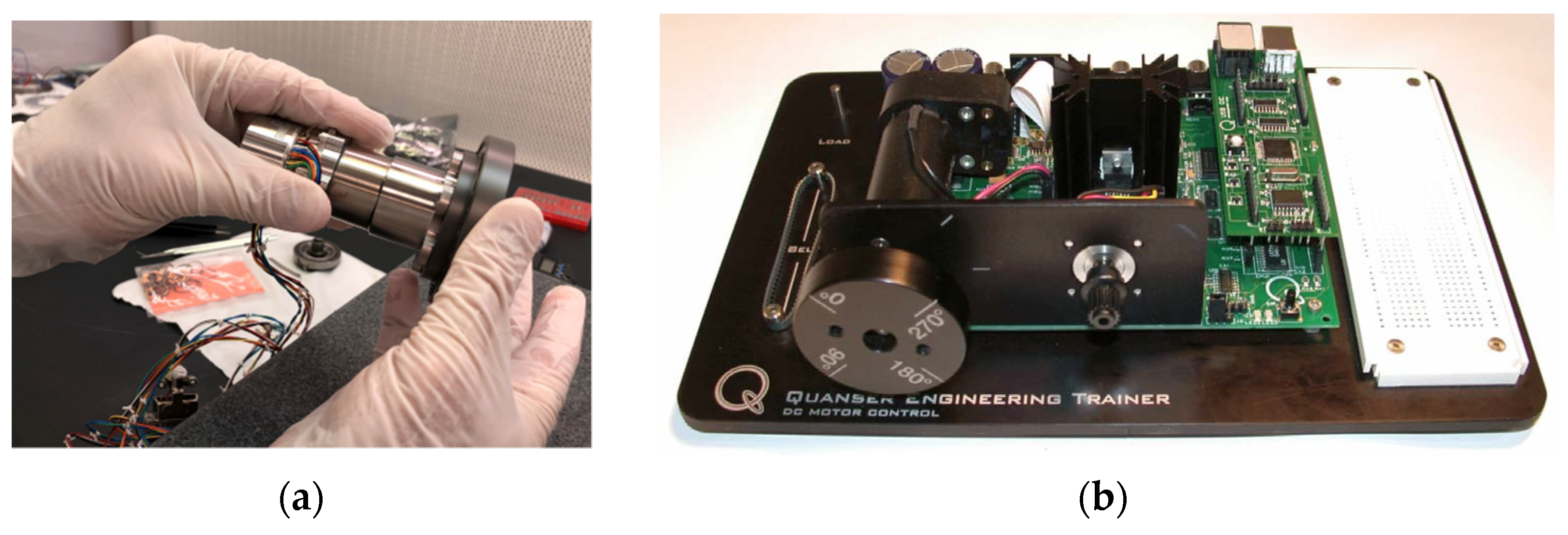
Direct current (DC) motors, illustrated in Figure 2, are a type of rotary electrical motor that converts direct current electrical energy into mechanical energy. DC motors were the first type of motor to receive widespread usage due to their ability to be powered by existing direct-current lighting power distribution systems. As a result, they are widely used as the driving mechanism for UAV propellers.
Control of DC motors is a classic topic, with recent novel methods such as deterministic artificial intelligence (DAI), as presented here, neural networks [7,8,9,10,11,12], and reinforcement learning [13], as well as other instantiations of neural network-based, stochastic artificial intelligence [14,15,16] being employed.
Khomenko et al. [9] sought optimal control of motor positioning using a combination of artificial neural network and state space methods with variable gain yielding a transient process close to optimal without overshoot. The approach proposed in this manuscript has a similar efficacy. Gesh et al. [10] investigated a dual implementation: a neural estimator used to estimate the motor speed and a neural controller used to generate a control signal for a converter, illustrating the effectiveness and advantages of the method in comparison with conventional control schemes. Naung et al. [11] demonstrated the improved speed and torque dynamic responses of DC motors by using a neural network parameter tuner with a classical proportional, integral controller. Yang et al. [12] proposed neural networks with output feedback to deal with DC motor measurement noise and unknown dynamics, including friction, parametric uncertainties, external disturbances, and unmodeled dynamics. Ćirić et al. [13] applied an adequate classifier based on a deep neural network, achieving accuracy of about 87% using only 668 data samples. Nizami et al. [14] proposed a single-functional-layer Legendre neural network integrated adaptive backstepping control technique and favorably compared the performance to the response obtained from proportional–integral–derivative controller. Lei et al. [15] proposed self-tuning and approximation via RBF neural networks, validating control system accuracy owing to its robustness and adaptability. Seeking to avoid corrective maintenance to reduce costs, Scalabrini et al. [16] used an artificial neural network for the prediction of motor failure time.
Just this year, Zhang et al. [17] appended a virtual DC motor control to the converter to effectively suppress the fluctuation of the DC bus reducing the rate to 9%, and the voltage recovery time was only 0.18 s. Tufenkci et al. [18] proposed reinforcement learning of PI control dynamics for optimal speed control of DC motors by using the Twin Delay Deep Deterministic Policy Gradient Algorithm. Munagala et al. [19] proposed controlling DC motor speed using a technique for identifying the system dynamics for neural network-based fractional-order proportional-integral derivative controller. With respect to computer numerical control machines, DC motors are still affected by transmission torque ripple, which mostly depends on the speed and the transient line current at the transmission interval, Prakash et al. [20] utilized a combination of so-called golden eagle optimization and a radial basis function neural network to reduce ripple to 1.26%. Ghany et al. [21] illustrated that an efficient interval type-2 fuzzy-based, single-neuron proportional–integral–derivative controller can improve dynamic motor response while accommodating system uncertainty. Baidya et al. [22] utilized a sensor feedback-supported controller based on a novel dandelion optimization PID controller, achieving integral square errors, integral absolute errors, integral errors, integral time square errors, and integral time absolute errors on the order of 10 2 . Sorfina et al. [23] illustrated that the deleterious impact on the performance of DC motors when utilized for photovoltaic cleaning system automation resulted in 14% failure rate. Mohanraj et al. [24] illustrated many advantages, including independent variable speed and variable torque operation along with regeneration capability when using DC motor-based electric drive systems by considering road friction, aerodynamic forces and transmission in the calculation of the motor shaft torque using model predictive control and proportional integral control, while only being able to assert the scheme makes significant energy capture possible. Thus, improvements that can be validated are continually being developed. Yang et al. [25] reported that efficiency as much as 15–20% higher was possible with a sliding-mode-based PID control, while merely asserting effectiveness. Tripathi et al. [26] proposed a quite novel fractional order adaptive Kalman filter for sensor-less motor speed control, but only achieved robustness and accuracy improvements in state estimation in comparison with extended Kalman filter instantiations. Saini et al. [27] claimed better performance using an enhanced hybrid stochastic fractal search controller. Rahman et al. [28] also tried a fractional transformation, but implemented it on an H-infinity controller. The results of that 2023 study should be considered a benchmark for the comparison of the results presented In this manuscript (noting the undershoot and overshoot characteristics).
Highlighting the vulnerability of conventional direct torque control to ripple, Kumar et al. [29] sought to achieve minimization and regulation of speed, where their novel instantiation of space vector pulse width modulation reduced the torque ripple by 63.1% when compared to conventional PI and 58.5% when compared to a second benchmark, a PSO-PI controller.
Mérida-Calvo et al. [30] also focused on commanded trajectory tracking seeking to address both time delays (tracking lag) and overshoots. They asserted that PID controllers did not yield a good tracking performance owing to friction nonlinearity, and proposed adding a prefilter combined with a Smith predictor, an anti-windup scheme, and a Coulomb friction compensator.
Vered et al. [31] used digital twins to remotely update feedback controllers, and the results produced very accurate trajectory tracking of square wave commands (while the overshoots and settling (also called “ringing”) remain a residual concern. The results recently achieved by Vered in 2023 make available a high-performance benchmark for comparing the results presented in this manuscript, where such tight target-tracking is sought without the “ringing”.
Improved performance was achieved by Gurumoorthy et al. [32], and the results modestly mimic the results presented in this manuscript, although the deleterious effects of noise remain prevalent.
Perhaps the proposals closest to those presented in this manuscript come from Stanford’s Moehle and Boyd [33], whose methods most closely mimic the proposed work, following the Cornell University line of research, where comparisons are made for sinusoidal versus optimal instantiations akin to the deterministic artificial intelligence methods to be proposed in this manuscript. Figures 6 and 8 in [33] illustrate the difficulty overcoming back electromagnetic force while attempting to follow a square wave. Very similar results were presented by Stanford’s Niemeyer et al. [34,35], and later by their colleague Diolaiti [36], illustrating the temporal longevity of the challenge identifying cancellation-replacement approaches experience performance limits due to sensor quantization, discretization, and amplifier bandwidths, where virtual stiffness was introduced to address these limitations.
On the other hand, the deterministic artificial intelligence method proposed in this manuscript utilizes self-awareness statements that are deterministic in nature to establish governing differential equations based on either the underlying physical properties of the problem or system identification methods [37,38,39,40,41,42,43,44,45,46,47]. This characteristic distinguishes it from the commonly used stochastic approaches in artificial intelligence, as it primarily employs first principles whenever feasible. Utilizing deterministic artificial intelligence principles instead of commonly used methods has the advantage of a simpler approach once re-parameterization has been derived. Despite being deterministic, its optimality in terms of self-awareness and learning can be readily understood by researchers who possess basic knowledge of linear regression.
Bernat et al. [37] proposed model-reference adaptive control, while Gowri et al. [38] proposed direct-induction motor torque control using a discontinuous pulse width modulation algorithm, seeking to reduce current ripples. Rathaiah et al. [39] optimized the adaptive control method, while Haghi et al. [40] made similar proposals using extremum-seeking methods. These approaches were in parallel with one of the predominant lines of physics-based work, that of the research group of Lorenz at the University of Wisconsin [41], and their efforts continue [42,43,44,45,46]. Zhang et al. [42] used an analogous three-phase motor illustrating efficacies applied to direct torque control of five phase motors. Apoorva et al. [43] extended Lorenz’s physics-based techniques to variable flux motors. Flieh et al. [44] illustrated loss minimization for various servo motors, in permanent magnet motor systems [45], and self-sensing via flux injection [46] with parallel application by Vidlak et al., illustrating ripple control [47]. The deterministic artificial intelligence proposed here adopts the physics-based feedforward approaches of Lorenz’s group, and that adoption necessitates prescribed trajectories.
When applying deterministic artificial intelligence, autonomous trajectory generation techniques are needed to approximate non-differentiable transient changes using a smooth curve. Two of the most widely used techniques for this purpose are the sinusoidal and Pontryagin methods. The latter involves utilizing boundary conditions to compute optimal trajectories based on control cost and will be compared to the sinusoidal method, which is a simpler technique for trajectory generation.
This manuscript expands on the analysis of deterministic artificial intelligence as presented in the following literature review, with the main purpose being to advocate for the commercial use of deterministic artificial intelligence in unmanned vehicles. The primary content of this manuscript consists of a detailed comparison of both discrete deterministic artificial intelligence and a selected state-of-the-art benchmark approach, with a specific focus on their trajectory-tracking capabilities when combined with different trajectory-generation methods. The comparison aims to provide a comprehensive evaluation of the strengths and weaknesses of each approach in the context of trajectory tracking, thereby aiding in a more informed decision-making process when selecting a suitable methodology for unmanned aerial vehicle applications.

1.2. State-of-the-Art Benchmarks

The following list highlights the current state-of-the-art developments in deterministic artificial intelligence:
  • In 2021, ref [48] revealed that deterministic artificial intelligence yielded a 4.8% lower mean and a 211% lower standard deviation for tracking errors compared to the best modeling method investigated (indirect self-tuner without zero cancellation process and minimum phase plant).
  • That same year, seeking to duplicate the results, Shah [49] found that deterministic artificial intelligence outperformed the model-following approach by a percent range of approximately 2–70% in terms of minimal peak transient value, but model-following achieved at least 29% less error in input tracking than deterministic artificial intelligence. This result was reported to be surprising, and not in accordance with the recently published literature, and the explanation for this difference was theorized to be the efficacy of discretized implementations.
  • The following year, in 2022, Koo et al. [50], in response to Shah’s recommended future research, investigated the impacts of discretization (timestep) and numerical propagation on the deterministic artificial intelligence approach.
  • In 2023, Menezes et al. [51] investigated the residual features of discretization methods, complementing the work of Koo, where the first-order hold method of discretization with a surprisingly large sample time of seven-tenths of a second yielded a greater than sixty percent improvement over the results presented in the previous literature. Deterministic artificial intelligence might seemingly be less susceptible to larger step sizes when using first-order hold discretization.
  • Subsequently in 2023, Wang et al. [52] investigated the step sizes necessary for discrete applications to approach the performance of the continuous application of deterministic artificial intelligence. The revealed error means were roughly approximate when the step size was reduced to 0.2 s.

1.3. Novelties Presented

The main contribution of this paper is the proposal of the Pontryagin-based method with deterministic artificial intelligence and the demonstration of its overall better performance. The following list presents the novelties presented in this manuscript towards the development of deterministic artificial intelligence.
  • The model-following self-tuner with five different parameter estimation methods is proposed and the performances compared; the best-performing one will serve as the state of the art.
  • Different from previous research using only sinusoidal trajectory generation, Pontryagin-based autonomous trajectory generation is proposed and combined with deterministic artificial intelligence for DC motors.
  • Comparisons are offered between deterministic artificial intelligence and the state-of-the-art model-following methodmethods using different trajectory-generation methods and the incomparable performance of discrete deterministic artificial intelligence augmented with the Pontryagin method when the step size is small is demonstrated.
  • A comparison is offered between continuous deterministic artificial intelligence using different trajectory-generation methods, and a possible breaking point in engineering applications (smallest error but high input value, which may exceed the maximum input for the DC motor) is revealed.

2. Materials and Methods

DC motors have been well studied using many methods, providing good comparative benchmarks. Section 2.1 elaborates on motor modeling. The canonical motor model from [53] with bump-test current regulation is integrated for voltage display, where the bump-test reasonably resembles each discontinuous jump of the square wave. The canonical model is available for purchase by readers seeking to repeat the work in this manuscript, with a designation of Quanser USB QICii, while the canonical motor is presented as Equation (2.6) in the laboratory workbook DC Motor Control Trainer (DCMCT), in Section 2.6.1.1 [53]. The description of the modules in the workbook elaborates the modeling methods for rate output. The author of the workbook is the same as for ref. [54], where the same motor model is assumed, providing the benchmark methods in this manuscript, serving as the starting point. This is important, as it allows researchers to duplicate these results.

2.1. Motor Modeling

In order to accurately describe the transfer function of a DC motor, it is necessary to use a continuous-time process and a normalized model to determine the voltage for the equivalent circuit model. This voltage is dependent on the current change at the operating point, which is in turn determined by the state of charge. By using Equation (1), the transfer function can be expressed in a clear and concise manner.
G s = B s A s = 1 s s + 1
The frequency domain depiction of the discrete time signal is shown in Equation (2). To obtain this, the signal was discretized using the zero-pole matching method with an initial continuous-time process of 0.35 s, implemented using the MATLAB® function c2d. The control signal and output in discrete time are denoted by U(z) and Y(z), respectively, using the z-transform. Equation (3) presents the resulting differential equation, along with the relevant variables and nomenclature defined in Table 1.
G z = Y z U z = 0.0517 z + 0.0517 z 2 1.7047 z + 0.7047
0.0517 u t + 0.0517 u t 1 = y t + 1 1.7047 y t + 0.7047 y t 1
To achieve stability, the model-following method can be applied to relocate the unstable pole present in the transfer function of the process to stable positions. However, this technique differs from deterministic artificial intelligence modeling, which does not emphasize pole relocation. Rather, it employs a proportional plus derivative (PD) feedback adaptation of unknown parameters to achieve autonomous tracking of the desired trajectory.

2.2. Model-Following Self-Tuner

A control system was established in this study, which employed a dynamic feedforward for the input u c and dynamic feedback for the output y. These were then combined to generate the process input u, as shown in Figure 3.3 in [54]. The model-following topology adopted in this study can be compared to the deterministic artificial intelligence topology depicted in Figure 3 in [52]. The system’s response can be described using Equations (4) and (5), where U(z) and Y(z) correspond to the z-transform of the control signal and control output, respectively.
Y z = B A T R U z S R Y z
G z = Y z U z = BT AR + BS
To obtain the desired transfer function of the system, cancellations are built into Equation (6), resulting in the numerator and denominator being factorized into several parts. The canceled zeros are represented by B + , while the uncancelled zeros are represented by B . B m represents a scalar multiple of the system, and A 0 represents pole-zero cancellations. The factorization of the numerator and denominator into these parts enables us to obtain the desired transfer function of the system.
Y z U z = B + B A 0 B m A 0 A m B + = BT AR + BS = B m A m
In order to ensure that the causality conditions are met, the polynomials R, S, and T are constrained to the first order, and B + is set to 1, since there will be no zero cancellation process. The coefficients of the polynomials R′, S, and T can be determined by manipulating Equation (6), while Equations (7)–(9) from [54] provide a way to express these coefficients in terms of the desired process parameters and their estimated values.
r 1 = b 1 b 0 + b 1 2 a m 1 b 0 b 1 + a m 2 b 0 2 b 1 + a 0 b 0 b 0 b 1 2 a 1 b 0 b 1 + a 2 b 0 2
s 0 = b 1 a 0 a m 1 a 2 a m 1 a 1 + a 1 2 + a m 2 a 1 a 0 b 1 2 a 1 b 0 b 1 + a 2 b 0 2 + b 0 a m 1 a 2 a 1 a 2 a 0 a m 2 + a 0 a 2 b 1 2 a 1 b 0 b 1 + a 2 b 0 2
s 1 = b 1 a 1 a 2 a m 1 a 2 + a 0 a m 2 a 0 a 2 b 1 2 a 1 b 0 b 1 + a 2 b 0 2 + b 0 a 2 a m 2 a 2 2 a 0 a m 2 a 1 + a 0 a 2 a m 1 b 1 2 a 1 b 0 b 1 + a 2 b 0 2
In order to combine feedforward and feedback, Equations (10) and (11) are used to express the control signal input to the process. Reference [54] emphasizes the importance of the parameter β in driving the system to unity gain, which is a crucial step in achieving zero asymptotic tracking error.
RU z = TU c z + SY z
u t = β U c t + β a 0 U c t 1 + s 0 Y t + s 1 Y t 1 r 1 U t 1
In this article, different parameter estimation methods will be presented and compared to estimate the unknown parameters. The methods that will be discussed are recursive least square (RLS), recursive least square with exponential forgetting (RLSwEF), auto regressive moving average (ARMA), extended least square (ELS), and extended least square with posterior residuals (ELSwPR).
Recursive least square is a widely used method for self-tuning model following, which recursively estimates the unknown parameters of a system by minimizing the squared error between predicted and actual output. Recursive least square with exponential forgetting is an extension that employs a forgetting factor to give more weight to recent data and prevent the algorithm from being overly influenced by past data. Auto regressive moving average is a method that models the process output as a combination of autoregressive and moving average components. Extended least square is another self-tuning method that extends the least square algorithm to estimate the parameters of a system using both input and output data. Extended least square with posterior residuals is a further extension that uses the residuals of the posterior mean estimate as a measure of the quality of the estimate and adaptively adjusts the forgetting factor to achieve better tracking performance. In this article, we present and compare these different parameter estimation methods.

2.3. Deterministic Artificial Intelligence

In order to establish the concept of self-awareness in the context of deterministic artificial intelligence, it is necessary to rearrange Equation (3) to isolate u t on the left-hand side. Through mathematical manipulation, as shown in Equation (12), u ( t ) can be represented as the product of a vector of knowns ϕ d and a vector of unknowns θ ˆ . The vector of knowns corresponds to the desired trajectory, while the vector of unknowns represents the learned parameters obtained from proportional plus derivative feedback used to generate the process input. Therefore, the regression form of the process input u(t) is expressed as u * t in Equations (13) and (14) whose variables are defined in Table 2.
u t = 1 0.0517 y t + 1 1.7047 0.0517 y t + 0.7047 0.0517 y t 1 u t 1
u * t = a ˆ 1 y d t + 1 a ˆ 2 y d t + a ˆ 3 y d t 1 b ˆ 1 u d t 1
u * t = ϕ d θ ˆ = y d t + 1 y d t + y d t 1 u d t 1 a ˆ 1 a ˆ 2 a ˆ 3 b ˆ 1
By utilizing feedforward control and transforming the state form y t to y t + 1   in Equation (12), it becomes possible to calculate the desired trajectory. The feedback parameters θ ˆ are updated through a recursive least squares process, which requires initial rough estimates of the feedback parameters, the output y, and the regression u * ( t ), all described in ref. [50]. Additionally, Equation (1)’s transfer function is converted back into an ordinary differential equation, which is reparametrized as shown in Equation (13).
Conversely, in continuous deterministic artificial intelligence, converting the transfer function in Equation (1) to an ordinary differential equation (ODE) and re-parametrizing it based on Equation (13) is necessary. Another approach is to apply Equation (14) and utilize optimal feedback adjustment for learning feedback parameters in a discrete manure, as proposed by Smeresky [55].
u ϕ d ϕ d T ϕ d 1 ϕ d T δ u

2.4. Autonomous Trajectory Generation

The purpose of autonomous trajectory generation for the DC motor or any other autonomous system is to generate the entire maneuver trajectory independently, based on a desired end state, without any external human assistance. While instantaneous maneuvering is possible in theory, the resulting trajectory would be a step function, lacking smoothness and containing discontinuities, making it impossible to differentiate. Therefore, an ideal trajectory should consist of three parts: the initial state, a smooth, continuously differentiable curve, and the desired end state.

2.4.1. Sinusoidal Trajectories

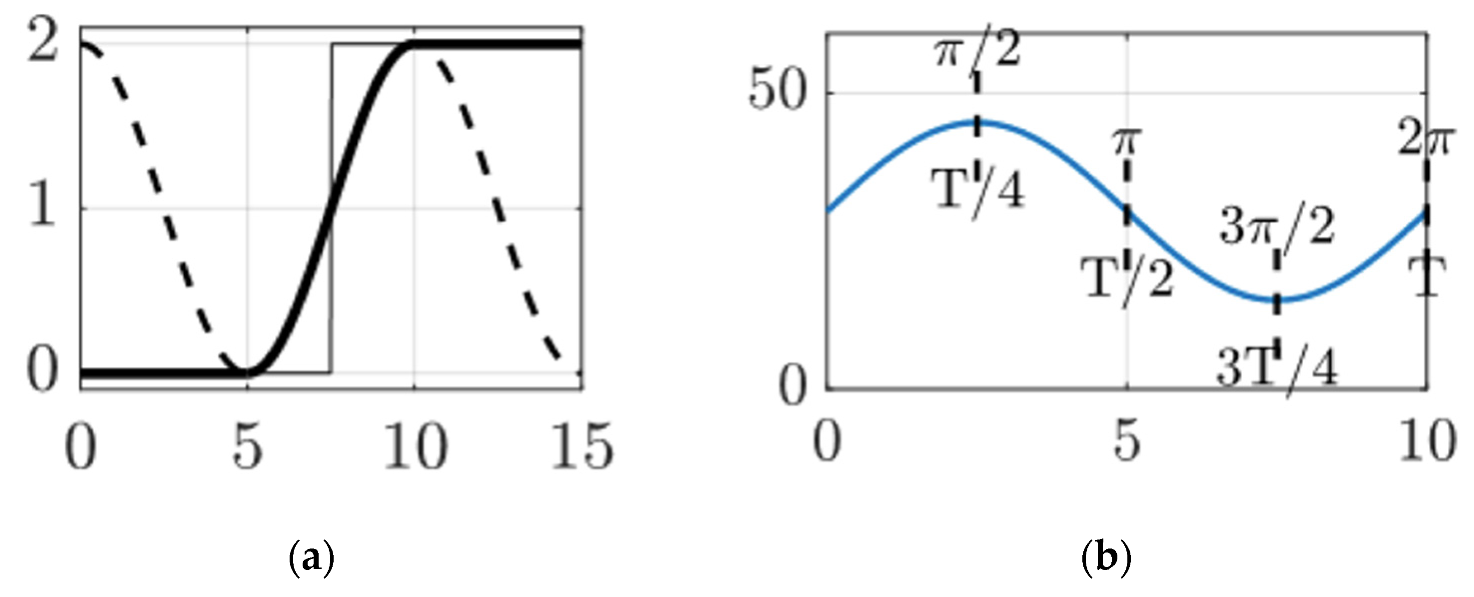
In most cases, system dynamics can be simplified or approximated to a basic ordinary differential equation of the form z ˙ = Az , which can be solved using z = Aexp λ t . This solution can then be transformed into a sinusoidal function of the form z = Asin ω t , as depicted in Figure 3. Therefore, one method of achieving autonomous trajectory generation is by computing a sinusoidal function based on the desired maneuver. The advantage of using a sinusoidal structure is that it can be easily differentiated and requires less computation compared to the Pontryagin method.
To achieve a smooth maneuver, the ideal derivative of the initial and terminal points of the generated trajectory should be zero. In Figure 3b, at time t = 3 T 4 , a smooth ascent is observed, indicating a derivative of zero that gradually increases, which represents an ideal starting point. The duration of the maneuver, represented by the hyperparameter Δ t , determines how long the entire slew will take. Equation (16) shows that to complete a full cycle from the valley (lowest value) to the peak (highest value) and result in a sinusoidal wave, the period required should be twice the slew time.
ω = 2 π T = 2 π 2 Δ t = π Δ t
To ensure that our sinusoidal function matches the desired initial and terminal states, it is necessary to calculate the phase shift and manipulate the amplitude. The resulting output can be represented by Equation (17), where A 0 and A f are the original and target states, respectively.
z = A f A 0 1 + sin ω t + ϕ
By joining the initial and the final state of the DC motor, the final state of the sinusoidal-based trajectory can be obtained, as shown in Equation (18).
for   { t < tstart θ = A 0 tstart <   t < tfinal θ = A f A 0 1 + sin ω t + ϕ t > tfinal θ = A f

2.4.2. Pontryagin-Based Trajectories

The Pontryagin method is a theory of optimal control that is a special case of the Euler–Lagrange equation in calculus. It can calculate the optimal control signal that enables a dynamic system to transition from one state to another while accounting for boundary conditions on the state or input control. This theory was proposed in 1956 by the Soviet mathematician Lev Pontryagin and his students.
Considering the dynamic function of the DC motor described by Equation (1), we can transform it using Equation (19) and obtain its dynamic equation as shown in Equation (20). This transformation allows us to model the behavior of the motor and analyze its response to various input signals more effectively.
Bs 2 + Bs   =   u , B ¨ + B ˙ = u
x ˙ = 0 1 0 1 x + 0 u
The Pontryagin-based trajectory-generation method is a comprehensive process that involves several steps. It all begins by formulating a target quadratic function that needs to be minimized, with boundary requirements. This quadratic function is represented in Equation (21).
Minimize   J x · , u · = 1 2 t 0 t f u 2 dt Subject   to   θ ¨ + θ ˙ = u t 0 = α t f = β θ 0 = A 0 θ f = A f ω ˙ 0 = 0 ω ˙ f = 0
The state of the DC motor is described by a two-dimensional vector [θ, ω], which represents motor’s angle and its angular velocity. The initial and final timestamps, t 0 and t f , are manually selected prior to the calculation. The initial and final states correspond to the motor angle and angular velocity, both of which are zero.
The Pontryagin principle consists of the following steps for solving a boundary value problem: (1) Formulate a Hamiltonian function based on the given cost function and dynamics; (2) Minimize the Hamiltonian with respect to the state variable; (3) Calculate the costate variable by taking the derivative of the Hamiltonian with respect to the state variable; (4) Generate appropriate boundary conditions to solve the boundary value problem.
The Hamilton function, denoted as H, is a combination of the target quadratic function and its boundary requirements, as shown in Equation (22). F represents the Lagrangian, λ is the costate or the adjoint variable, f(x,u) represents the system dynamics, x is the state variable, and u is the control variable.
Hamilton   function   H = F + λ T f x , u H = 1 2 u 2 + λ 1 x ˙ + λ 1 x ¨ H = 1 2 u 2 + λ 1 x ˙ + λ 2 x ˙ + u
The Pontryagin principle asserts that the optimal solution to an optimal control problem can be obtained by setting the derivative of the Hamiltonian with respect to the control variable to zero.
dH du = 2 u + λ 2 = 0 u = λ 2 2
Afterwards, the next step involves equating the derivative of the Hamiltonian with respect to the system’s states to the negative derivative of the costates.
dH d x ˙ = λ 1 ˙ = 0 λ 1 = a dH d x ¨ = λ 2 ˙ = λ 1 λ 2 = a λ 2
Thus, the boundary value problem is now transformed as
θ ¨ + θ ˙ = u t 0 = α t f = β θ 0 = A 0 θ f = A f ω ˙ 0 = 0 ω ˙ f = 0 u = λ 2 2 λ 1 = a λ 2 ˙ = a λ 2
Solving the differential equation yields the function for the input value u:
λ 2 = e t c 1 + a u = 1 2 e t c 1 1 2 a
After that, the optimal trajectory can be calculated by taking advantage of Equation (18).   c 2 ,   c 1 , c and a are all unknown parameters that can be calculated by the boundary equation.
ω = e t c 1 e t + t 2 e c + at 2 e t e t 1 2 e c + c 1 e t + a 2 e t + at 2 e t c 2 e t θ = c 2 e t e t c 1 e t + t 2 e c + at 2 e t
Finally, an optimal trajectory based on the Pontryagin principle was constructed using a piecewise continuous function. The trajectory consisted of a period of inactivity, followed by the exponential function generated in the previous steps, which lasted for a duration of Δ t . The trajectory then concluded with a period of constant final attitude.
for   { t < tstart θ = A 0 tstart <   t < tfinal θ = c 2 e t e t c 1 e t + t 2 e c + at 2 e t t > tfinal θ = A f
Regarding the time complexity of the proposed methods, the Pontryagin-based trajectory-generation method is more complex than the sinusoidal method, as it requires the calculation of two differential equations. However, these calculations are fixed once applied to the DC motor, and can be pre-computed and applied to an edge-computing platform, such as an embedded system for the DC motor controller. Both the continuous and discrete deterministic artificial intelligence methods share the same time complexity, as they use the same physics-based assertion. The time complexity of the PD-based adaptation for the deterministic artificial intelligence method is O(N), due to its simple feed-forward nature, while the optimal learning-based deterministic artificial intelligence method has a time complexity of O(N3) due its calculation of the reverse matrix, which is relatively time consuming. Additionally, it is necessary to point out that when the time step is smaller, its frequency will be increased, which results in higher computational demands.

3. Results

The purpose of this section is to provide a comprehensive comparison of several widely used model-following self-tuning techniques, including recursive least square, recursive least square with exponential forgetting, auto regressive moving average, extended least square, and extended least square with posterior residuals, when applied to DC motors. The focus is on their performance. In this regard, after identifying the state-of-the-art methods in the previous section, these will then be compared with the discrete deterministic artificial intelligence approach presented in Equation (14). This comparison will be carried out using both sinusoidal and Pontryagin-based trajectory-generation methods. Moreover, the comparison between continuous and discrete deterministic artificial intelligence will be analyzed in terms of trajectory-following accuracy and input value range. It is expected that the results of this comparison will demonstrate the superiority of the discrete deterministic artificial intelligence method augmented with Pontryagin-based trajectory-generation method.
MATLAB® R2021b is the software required to run the code, and other MATLAB® versions may cause unexpected errors. The MATLAB code used in this paper is available open source at JiahaoXU9/DC_Motor_DAI Public. Available online: https://github.com/JiahaoXU9/DC_Motor_DAI.git (accessed 1 April 2023).

3.1. Different Model-Following Self-Tuner Control Benchmarks

As explained in Section 2 of this paper, the model-following self-tuner is an estimation approach based on the model, which is used to generate control input to follow a desired trajectory. To implement Equation (14), various estimation techniques are used to adaptively calculate the unknown parameters. This section presents a comparison of the methods employed for an assumed model, followed by a comparison with the DC motor model in Equation (29) to identify the state-of-the-art methods for comparison with deterministic artificial intelligence.
y t = 9 20 y t 1 + 3 40 y t 2 + 1 40 y t 3 + 3 u t 1 + 2 3 u t 2 1 9 u t 3 ) 1 10 ε t
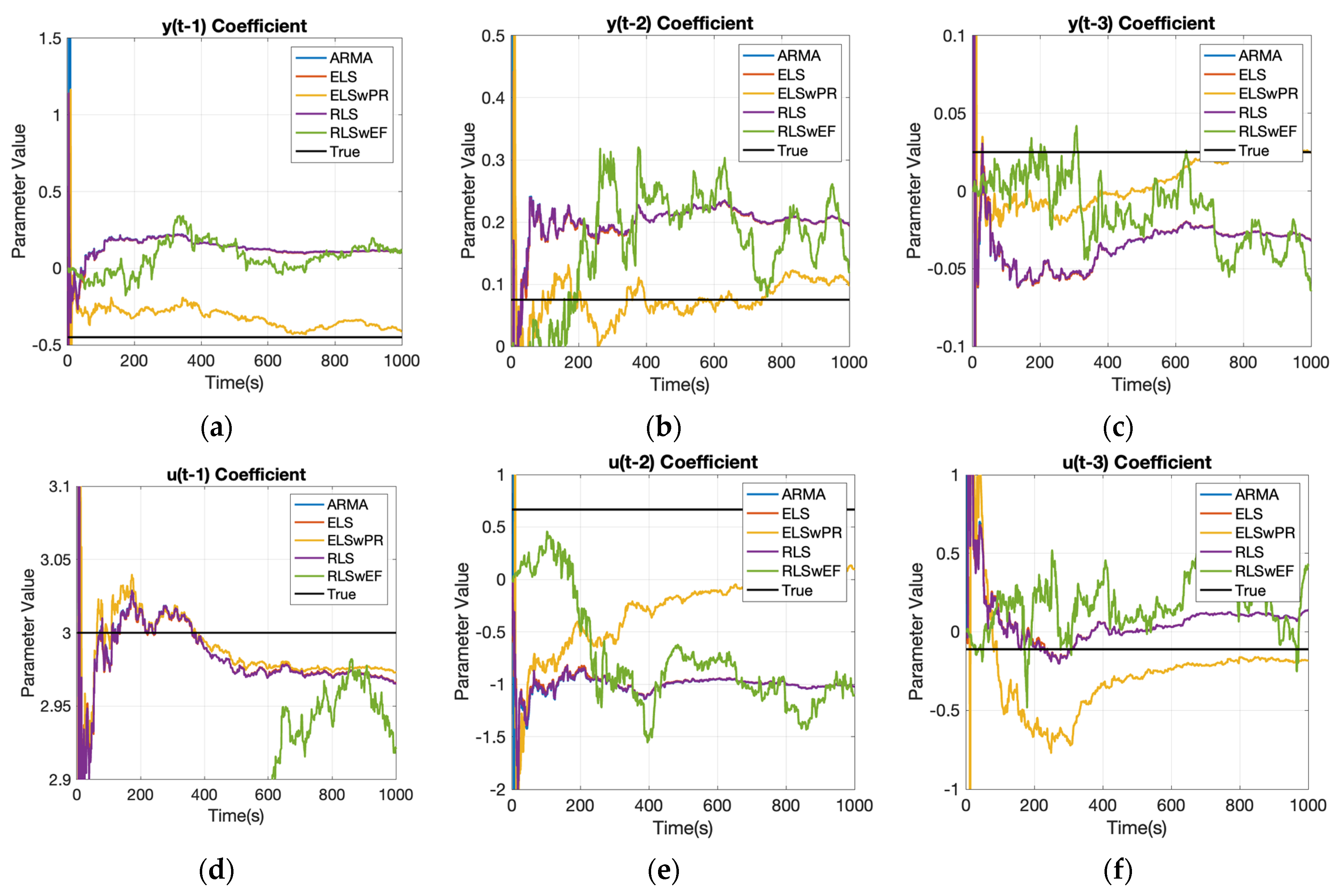
Assuming a truth model with an uncorrelated output noise term ε(t) = N (0,1), history data for 1000 time samples are generated according to Equation (28). Figure 4 displays the estimation changes with increasing timestamp, while Table 3 provides detailed values regarding the differences between each method.
Figure 4 and the data in the table indicate that extended least square with posterior residuals provides the most accurate estimates for the parameter y(t − 1) and u(t − 1), recursive least square with exponential forgetting is best for estimating y(t − 2) and u(t − 2), recursive least square yields the most accurate estimates for y(t − 3), and auto regressive moving average is most effective for estimating u(t − 3). This suggests that different methods have varying levels of efficacy for estimating different parameters. Determining the optimal method for a given task requires a comprehensive understanding of the employed model and the specific parameters being estimated. Consequently, the subsequent phase of this study involves implementing these methods on the DC motor to evaluate and compare their respective performances.
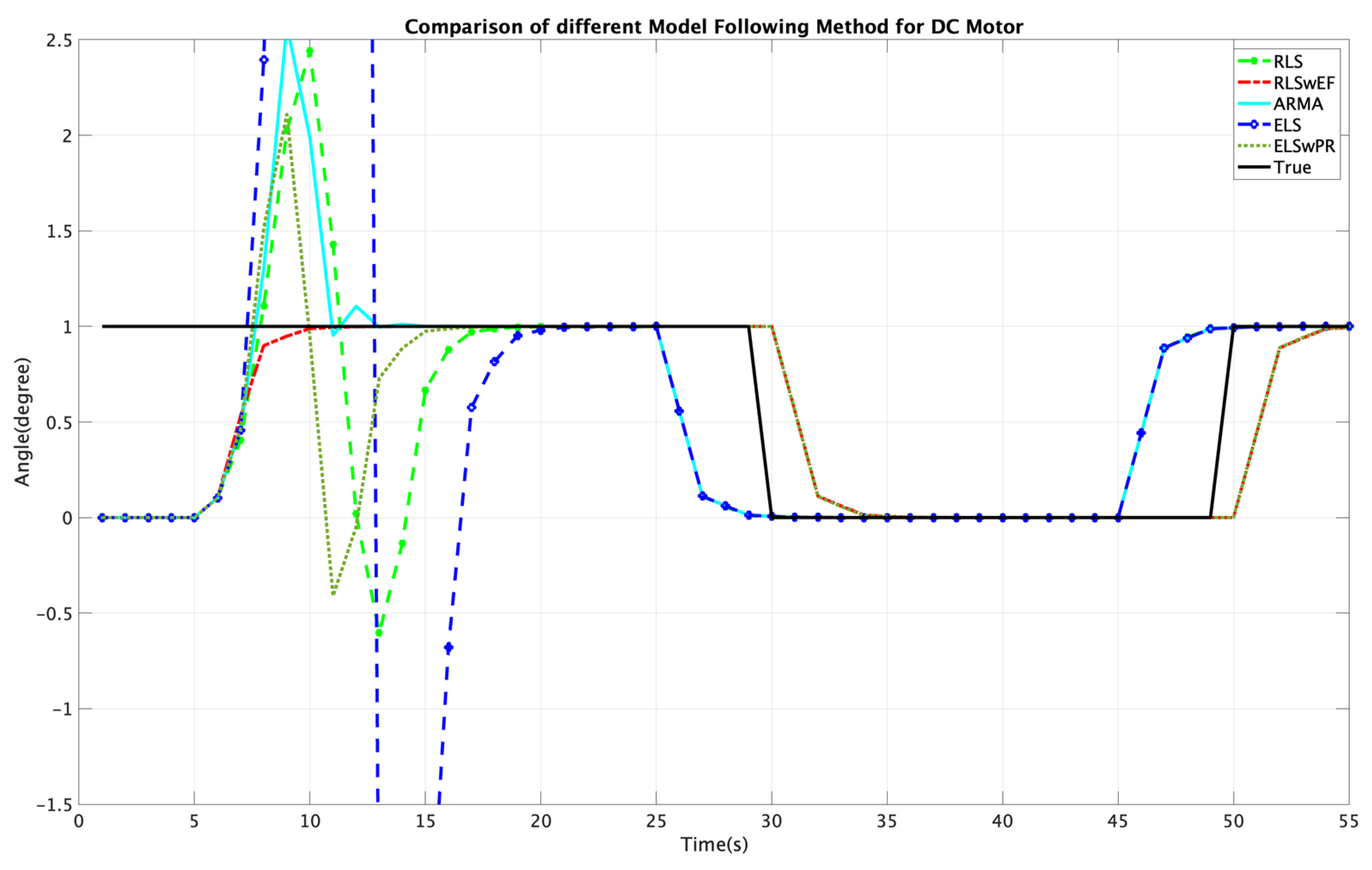
To achieve the effective self-tuning of a system, it is crucial to design a control system that can convert unstable system responses into stable ones. This ensures that the output does not diverge, and that the inputs can be tracked asymptotically. The step size of the system discretization is a critical factor that significantly impacts the overall tracking performance of the system. To evaluate the effectiveness of different parameter estimation methods for the DC motor system, we utilize three evaluation metrics: absolute mean error, absolute standard deviation, and total input value. These metrics consider both accuracy and system efficiency, enabling objective comparison among the estimation methods.
The evaluation results presented in Figure 5 and Table 4 demonstrate that the recursive least square with exponential forgetting method outperforms the other methods in terms of both mean error and error standard deviation for step sizes of t = 0.35 and t = 0.5. The extended least square with posterior residuals method ranks second in performance, with an increase in mean error of 41.9% and 31.6%, and an increase in error standard deviation of 42.0% and 25.4%, respectively. Although the total input value evaluation indicates that the recursive least square with exponential forgetting method does not perform as well as the extended least square method, this factor is of relatively lower priority. Therefore, based on the comprehensive evaluation metrics, the recursive least square with exponential forgetting method is considered to be the state-of-the-art model-following approach, and will be used as the benchmark for evaluating deterministic artificial intelligence with different trajectory-generation methods.

3.2. Discrete Deterministic Artificial Intelligence with Different Trajectory-Generation Methods

This section aims to apply the discrete deterministic artificial intelligence approach to the DC motor system with two different trajectory-generation methods, namely, the sinusoidal and Pontryagin methods. The purpose of this is to compare the results obtained from these methods with the state-of-the-art recursive least square with exponential forgetting method discussed in Section 3.1. The performance is evaluated on the basis of the mean error, standard deviation, and mean input value, which is consistent with the evaluation metrics used in the previous sections.
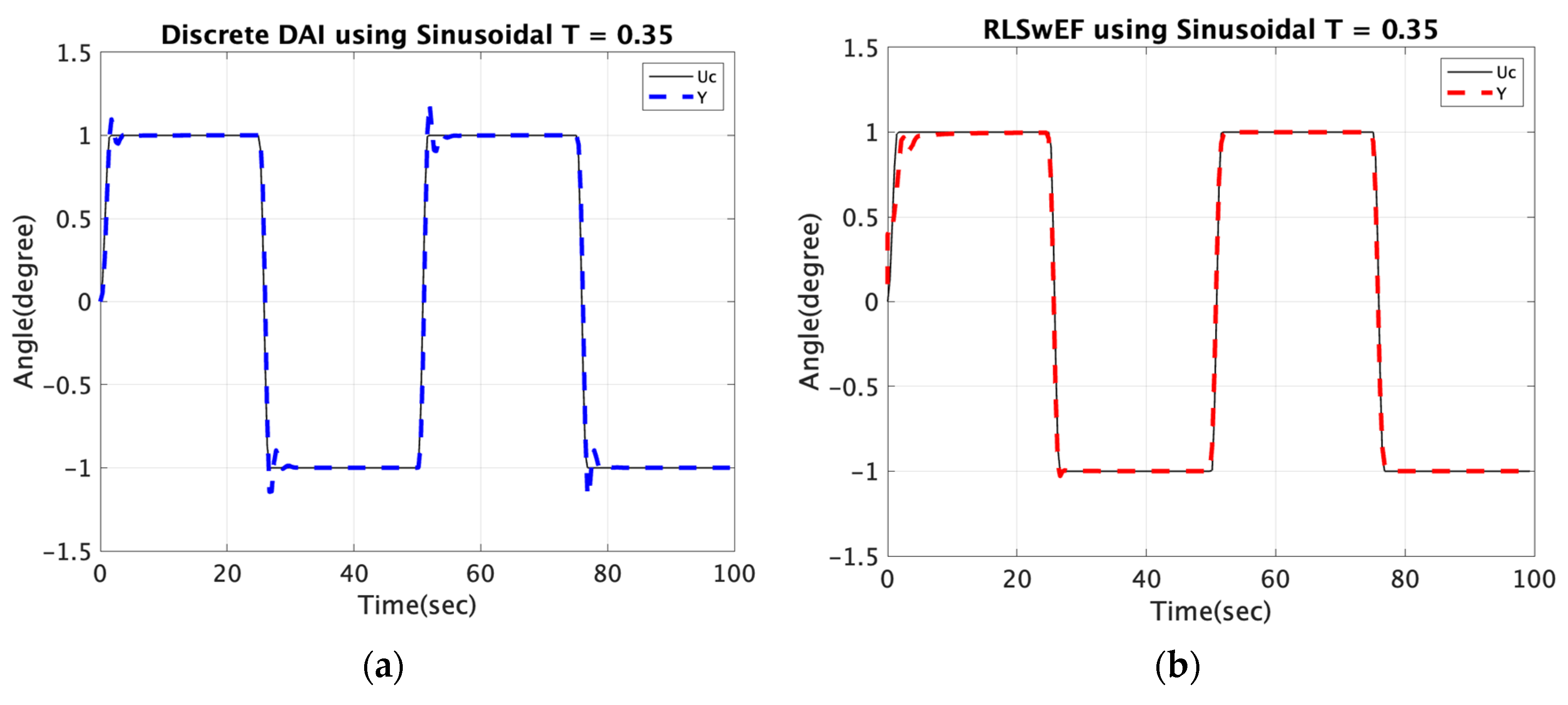
Upon examining the data presented in Table 5, it becomes apparent that the recursive least square with exponential forgetting method yields superior results compared to the deterministic artificial intelligence technique when the step size is set to 0.5. Nevertheless, it is crucial to recognize that a step size of this magnitude may not be suitable for real-world scenarios, as it could fail to capture the slew transfer accurately and in a timely fashion. Consequently, it is the outcomes in Table 5 and Figure 6 obtained using smaller step sizes that bear greater significance and practicality for implementation purposes. Therefore, it is vital to consider the performance of the methods under smaller step sizes when evaluating and selecting a model-following approach.
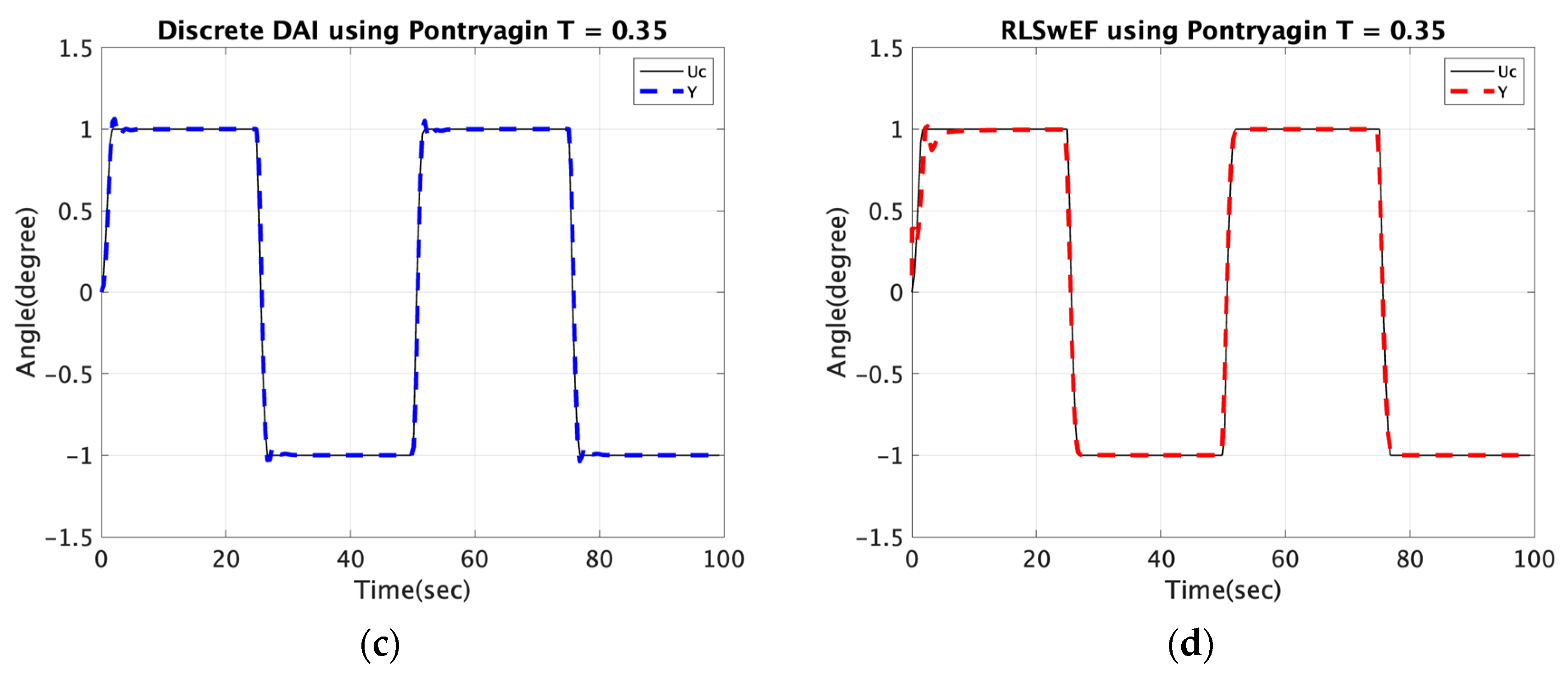
With decreasing time step, the performance of the evaluated methods becomes more reliable. Specifically, for a time step of 0.4, both the deterministic artificial intelligence and recursive least square with exponential forgetting methods exhibit the same mean error. However, the deterministic artificial intelligence approach shows a slightly smaller standard deviation but a larger input value. This suggests that while both methods have similar accuracy, the deterministic artificial intelligence approach may be more efficient in terms of resource usage. However, when the time step is decreased to 0.35, the deterministic artificial intelligence approach outperforms the recursive least square with exponential forgetting method in both mean error and standard deviation, thereby validating the effectiveness of the former approach. It is worth noting that the output of deterministic artificial intelligence exhibits an overshoot at discontinuities and tracks the input signal with a small tracking error, which is consistent with the observations made by Koo [9]. Moreover, it is worth highlighting that the increase in output observed upon decreasing the step size from 0.4 to 0.35 is not indicative of a decrease in performance, but rather reflects the fact that more time steps are required to output larger values.
After conducting our analysis, we can also conclude that the Pontryagin-based trajectory-generation method consistently outperforms the sinusoidal method across all three evaluation metrics when the same method and step size are employed. This finding provides strong evidence for the effectiveness of the Pontryagin method. Moreover, this observation is consistent with the underlying mathematical principle, as the Pontryagin method seeks an optimal trajectory directly from the functional, resulting in a non-approximate solution. In contrast, the sinusoidal trajectory is an approximate solution, and therefore, it is expected to be less effective.

3.3. Continous Deterministic Artificial Intelligence with Different Trajectory-Generation Methods

Compared to discrete deterministic artificial intelligence, continuous deterministic artificial intelligence utilizes ordinary differential equations to simulate system dynamics. Table 6 and Figure 7 present a comparative analysis between the two approaches, considering both sinusoidal and Pontryagin-based methodologies.
Table 6 demonstrates that continuous deterministic artificial intelligence outperforms the discrete alternative with a time step size of 0.5, but discrete deterministic artificial intelligence using the Pontryagin-based methodology achieves superior performance when the time step size decreases to 0.35. The robustness of continuous deterministic artificial intelligence across varying time step sizes further confirms its reliability. Moreover, the Pontryagin method consistently outperforms the sinusoidal method in terms of mean error and standard deviation, indicating its effectiveness. However, it is worth noting that the Pontryagin method may sometimes require larger input values than the sinusoidal method, potentially due to errors in solving ordinary differential equations. This issue could be explored further in future work.

4. Discussion

Table 7 and Table 8 demonstrates the improvement in performance achieved for different algorithms when utilizing different trajectory-generation methods. Our findings validate the effectiveness of the deterministic artificial intelligence approach, particularly when combined with the Pontryagin-based trajectory-generation method, for accurately tracking discontinuous command square waves compared to alternative techniques. Additionally, it should be noted that continuous deterministic artificial intelligence requires large input values, which may represent a potential limitation when applying this approach to real-world problems.
Our manuscript presents a comprehensive analysis of the control effects of various control algorithms and compares their performance at different step sizes. We observe that, with decreasing step size, the discrepancy between the output signals generated by different algorithms gradually decreases, and eventually becomes negligible. Additionally, our findings indicate that the Pontryagin-based trajectory-generation method consistently outperforms the sinusoidal method due to its superior mathematical properties. In terms of overall performance, discrete deterministic artificial intelligence appears to be the most effective with small step sizes, followed by continuous deterministic artificial intelligence. However, since continuous deterministic artificial intelligence offers superior performance compared to other approaches across various computation rates, it may represent the most feasible and reliable option for future applications on unmanned vehicles, provided its input value does not exceed the input limit.

5. Conclusions and Future Research

5.1. Conclusions

Our manuscript presents a simulation-based comparison of the performance of continuous and discrete deterministic artificial intelligence models, along with a model-following benchmark, using both Pontryagin and sinusoidal trajectory-generation methods for the DC motor. The Pontryagin-based optimal trajectory with deterministic artificial intelligence for DC motors was proposed, and its performance compared, for the first time in this paper. Our findings reveal the superiority of discrete deterministic artificial intelligence augmented with the Pontryagin method, particularly at small step sizes.
However, although continuous deterministic artificial intelligence demonstrates robustness across different time steps, our study also highlights a potential limitation in real-world applications. Specifically, we found that large input values may be required that may exceed the maximum input capacity of the DC motor. This observation suggests that careful consideration must be given to input values when using continuous deterministic artificial intelligence models for practical applications.
Overall, our study provides valuable insights into the performance of different artificial intelligence models and trajectory-generation methods in the context of a DC motor. Our results can serve to inform the development of more effective and practical control systems for similar unmanned vehicle applications.

5.2. Future Research

This paper presents several novel discoveries, but there are also several areas for future exploration. One such area is the need for further research into the reason for the larger input values required when combining continuous deterministic artificial intelligence with the Pontryagin method. Additionally, developing an effective method to eliminate overshot and errors in the initial part of continuous deterministic artificial intelligence and the transient part of discrete deterministic artificial intelligence would enhance their appeal for real-world applications.

Author Contributions

Conceptualization, J.X. and T.S.; methodology, J.X. and T.S.; software, J.X. and T.S.; validation, T.S.; formal analysis, J.X. and T.S.; investigation, J.X. and T.S.; resources, T.S.; writing—original draft preparation, J.X.; writing—review and editing, J.X. and T.S.; supervision, T.S.; funding acquisition, T.S. All authors have read and agreed to the published version of the manuscript.

Funding

This research received no external funding.

Data Availability Statement

Data supporting reported results can be obtained by contacting the corresponding author.

Conflicts of Interest

The authors declare no conflict of interest.

References

  1. Gómez-Peñate, S.; López-Estrada, F.-R.; Valencia-Palomo, G.; Rotondo, D.; Guerrero-Sánchez, M.-E. Actuator and sensor fault estimation based on a proportional multiple-integral sliding mode observer for linear parameter varying systems with inexact scheduling parameters. Int. J. Robust Nonlinear Control 2021, 31, 8420–8441. [Google Scholar] [CrossRef]
  2. Blake, T. What is Unmanned Aircraft Systems Traffic Management? 27 May 2021. Available online: https://www.nasa.gov/ames/utm (accessed on 3 March 2023).
  3. Tabor, A. New Era Begins as Drone Traffic Management Project Wraps Up. 22 June 2021. Available online: https://www.nasa.gov/feature/ames/new-era-begins-as-drone-traffic-management-project-wraps-up (accessed on 3 March 2023).
  4. NASA Image Use Policy. Available online: https://gpm.nasa.gov/image-use-policy (accessed on 3 March 2023).
  5. Guerges, M. NASA Integrates Gear Motors for Robotic Arm on Future Lunar Missions. Available online: https://www.nasa.gov/feature/nasa-integrates-gear-motors-for-robotic-arm-on-future-lunar-missions (accessed on 19 February 2023).
  6. Apkarian, J.; Åström, J. A laptop servo for control education. IEEE Contr. Syst. Mag. 2004, 24, 70–73. [Google Scholar]
  7. Hoque, M.A.; Zaman, M.R.; Rahman, M.A. Artificial neural network based permanent magnet DC motor drives. In Proceedings of the IAS’95. Conference Record of the 1995 IEEE Industry Applications Conference Thirtieth IAS Annual Meeting, Orlando, FL, USA, 8–12 October 1995; pp. 98–103. [Google Scholar] [CrossRef]
  8. Hoque, M.A.; Zaman, M.R.; Rahman, M.A. Artificial neural network based controller for permanent magnet dc motor drives. In Proceedings of the IAS’95. Conference Record of the 1995 IEEE Industry Applications Conference Thirtieth IAS Annual Meeting, Orlando, FL, USA, 8–12 October 1995; Volume 2, pp. 1775–1780. [Google Scholar] [CrossRef]
  9. Khomenko, M.; Voytenko, V.; Vagapov, Y. Neural network-based optimal control of a DC motor positioning system. Int. J. Autom. Control 2013, 7, 83–104. [Google Scholar] [CrossRef]
  10. Yogesh, S.; Gupta, M.; Garg, M. DC Motor Speed Control using Artificial Neural Network. Int. J. Mod. Commun. Technol. Res. 2014, 2, 19–24. [Google Scholar]
  11. Naung, Y.; Anatolii, S.; Lin, Y. Speed Control of DC Motor by Using Neural Network Parameter Tuner for PI-controller. In Proceedings of the IEEE Conference of Russian Young Researchers in Electrical and Electronic Engineering (EIConRus), Saint Petersburg and Moscow, Russia, 28–31 January 2019; pp. 2152–2156. [Google Scholar]
  12. Yang, X.; Deng, W.; Yao, J. Neural network based output feedback control for DC motors with asymptotic stability. Mech. Syst. Signal Process. 2022, 164, 108288. [Google Scholar] [CrossRef]
  13. Ćirić, D.; Janković, M.; Miletić, M. Sound Based DC Motor Classification by a Convolution Neural Network. In Proceedings of the 57th International Scientific Conference on Information, Communication and Energy Systems and Technologies (ICEST), Ohrid, North Macedonia, 16–18 June 2022; pp. 1–4. [Google Scholar] [CrossRef]
  14. Nizami, T.; Gangula, S.; Reddy, R.; Dhiman, H. Legendre Neural Network based Intelligent Control of DC-DC Step Down Converter-PMDC Motor Combination. IFAC-Pap. 2022, 55, 162–167. [Google Scholar] [CrossRef]
  15. Lei, G.; Xie, L.; Ni, W.; Zheng, S. Self-tuning and approximation via RBF neural networks. In Proceedings of the 7th International Conference on Control Engineering and Artificial Intelligence CCEAI ’23, Sanya, China, 28–30 January 2023; pp. 72–78. [Google Scholar] [CrossRef]
  16. Scalabrini Sampaio, G.; Vallim Filho, A.R.d.A.; Santos da Silva, L.; Augusto da Silva, L. Prediction of Motor Failure Time Using an Artificial Neural Network. Sensors 2019, 19, 4342. [Google Scholar] [CrossRef] [Green Version]
  17. Zhang, L.; Wang, Y.; Cheng, L.; Kang, W. A Three-Parameter Adaptive Virtual DC Motor Control Strategy for a Dual Active Bridge DC–DC Converter. Electronics 2023, 12, 1412. [Google Scholar] [CrossRef]
  18. Tufenkci, S.; Alagoz, B.; Kavuran, G.; Yeroglu, C.; Herencsar, N.; Mahata, S. A theoretical demonstration for reinforcement learning of PI control dynamics for optimal speed control of DC motors by using Twin Delay Deep Deterministic Policy Gradient Algorithm. Expert Syst. Appl. 2023, 213, 119192. [Google Scholar] [CrossRef]
  19. Munagala, V.K.; Jatoth, R.K. A novel approach for controlling DC motor speed using NARXnet based FOPID controller. Evol. Syst. 2023, 14, 101–116. [Google Scholar] [CrossRef]
  20. Prakash, A.; Naveen, C. Combined strategy for tuning sensor-less brushless DC motor using SEPIC converter to reduce torque ripple. ISA Trans. 2023, 133, 328–344. [Google Scholar] [CrossRef] [PubMed]
  21. Ghany, M.; Shamseldin, M. Fuzzy type two self-tuning technique of single neuron PID controller for brushless DC motor based on a COVID-19 optimization. Int. J. Pow. Elec. Dr. Sys. 2023, 14, 562. [Google Scholar] [CrossRef]
  22. Baidya, D.; Dhopte, S.; Bhattacharjee, M. Sensing System Assisted Novel PID Controller for Efficient Speed Control of DC Motors in Electric Vehicles. IEEE Sens. Lett. 2023, 7, 1–4. [Google Scholar] [CrossRef]
  23. Sorfina, U.; Islam, S.; Ching, K.; Soomro, D.; Yahaya, J. Adaptive position control of DC motor for brush-based photovoltaic cleaning system automation. Bulletin Electr. Eng. Info. 2023, 12, 1293–1301. [Google Scholar]
  24. Mohanraj, N.; Kathirvelu, P.; Balasubramanian, R.; Sankaran, R.; Amirtharajan, R. Design of Permanent Magnet Brushless DC Motor Drive System for Energy Recouping in an Electric Automobile. Arab. J. Sci. Eng. 2023, 48. [Google Scholar] [CrossRef]
  25. Yang, W.; Zhu, Y.; Wang, C.; Li, P.; Liu, Y. Research on Simulation Model Control Strategy of Brushless DC Motor Based on MATLAB. In Proceedings of the World Conference on Intelligent and 3-D Technologies (WCI3DT 2022). Smart Innovation, Systems and Technologies; Kountchev, R., Nakamatsu, K., Wang, W., Kountcheva, R., Eds.; Springer: Singapore, 2023; Volume 323. [Google Scholar]
  26. Tripathi, R.; Singh, A.; Gangwar, P. Fractional order adaptive Kalman filter for sensorless speed control of DC motor. Int. J. Electron. 2023, 110, 373–390. [Google Scholar] [CrossRef]
  27. Saini, R.; Parmar, G.; Gupta, R. Chapter 4—An enhanced hybrid stochastic fractal search FOPID for speed control of DC motor. In Fractional Order Systems and Applications in Engineering; Academic Press: Cambridge, MA, USA, 2023; pp. 51–67. ISBN 9780323909532. [Google Scholar]
  28. Rahman, M.Z.U.; Leiva, V.; Martin-Barreiro, C.; Mahmood, I.; Usman, M.; Rizwan, M. Fractional Transformation-Based Intelligent H-Infinity Controller of a Direct Current Servo Motor. Fractal Fract. 2023, 7, 29. [Google Scholar] [CrossRef]
  29. Kumar, M.; Satheesh, G.; Peddakotla, S. Design of optimal PI controller for torque ripple minimization of SVPWM-DTC of BLDC motor. Int. J. Pow. Elect. Dr. Sys. 2023, 14, 283–293. [Google Scholar] [CrossRef]
  30. Mérida-Calvo, L.; Rodríguez, A.S.-M.; Ramos, F.; Feliu-Batlle, V. Advanced Motor Control for Improving the Trajectory Tracking Accuracy of a Low-Cost Mobile Robot. Machines 2023, 11, 14. [Google Scholar] [CrossRef]
  31. Vered, Y.; Elliott, S. The use of digital twins to remotely update feedback controllers for the motion control of nonlinear dynamic systems. Mech. Syst. Signal Process. 2023, 185, 109770. [Google Scholar] [CrossRef]
  32. Gurumoorthy, K.; Balaraman, S. Controlling the Speed of renewable-sourced DC drives with a series compensated DC to DC converter and sliding mode controller. Automatika 2023, 64, 114–126. [Google Scholar] [CrossRef]
  33. Moehle, N.; Stephen Boyd, S. Optimal current waveforms for brushless permanent magnet motors. Int. J. Control 2015, 88, 1389–1399. [Google Scholar] [CrossRef]
  34. Günter, N.; Nicola, D.; Neal, T. Wave Haptics: Encoderless. Virtual Stiffnesses 2005, 28, 22–33. [Google Scholar] [CrossRef]
  35. Niemeyer, G.; Diolaiti, N.; Tanner, N. Wave Haptics: Encoderless Virtual Stiffnesses. In Robotics Research; Thrun, S., Brooks, R., Durrant-Whyte, H., Eds.; Springer Tracts in Advanced Robotics; Springer: Berlin/Heidelberg, Germany, 2007; Volume 28. [Google Scholar]
  36. Diolaiti, N.; Niemeyer, G.; Tanner, N.A. Wave Haptics: Building Stiff Controllers from the Natural Motor Dynamics. Int. J. Robot. Res. 2007, 26, 5–21. [Google Scholar] [CrossRef]
  37. Bernat, J.; Stepien, S. The adaptive speed controller for the BLDC motor using MRAC technique. IFAC Proc. Vol. 2011, 44, 4143–4148. [Google Scholar] [CrossRef] [Green Version]
  38. Gowri, K.; Reddy, T.; Babu, C. Direct torque control of induction motor based on advanced discontinuous PWM algorithm for reduced current ripple. Electr. Eng. 2010, 92, 245–255. [Google Scholar] [CrossRef]
  39. Rathaiah, M.; Reddy, R.; Anjaneyulu, K. Design of Optimum Adaptive Control for DC Motor. Int. J. Electr. Eng. 2014, 7, 353–366. [Google Scholar]
  40. Haghi, P.; Ariyur, K. Adaptive First Order Nonlinear Systems Using Extremum Seeking. In Proceedings of the 50th Annual Allerton Conference on Communication Control, Monticello, IL, USA, 1–5 October 2012; pp. 1510–1516. [Google Scholar]
  41. Available online: https://site.ieee.org/ias-idc/2019/01/29/prof-bob-lorenz-passed-away/ (accessed on 12 December 2022).
  42. Zhang, L.; Fan, Y.; Cui, R.; Lorenz, R.; Cheng, M. Fault-Tolerant Direct Torque Control of Five-Phase FTFSCW-IPM Motor Based on Analogous Three-phase SVPWM for Electric Vehicle Applications. IEEE Trans. Veh. Technol. 2018, 67, 910–919. [Google Scholar] [CrossRef]
  43. Apoorva, A.; Erato, D.; Lorenz, R. Enabling Driving Cycle Loss Reduction in Variable Flux PMSMs Via Closed-LoopMagnetization State Control. IEEE Trans. Ind. Appl. 2018, 54, 3350–3359. [Google Scholar]
  44. Flieh, H.; Lorenz, R.; Totoki, E.; Yamaguchi, S.; Nakamura, Y. Investigation of Different Servo Motor Designs for Servo Cycle Operations and Loss Minimizing Control Performance. IEEE Trans. Ind. Appl. 2018, 54, 5791–5801. [Google Scholar] [CrossRef]
  45. Flieh, H.; Lorenz, R.; Totoki, E.; Yamaguchi, S.; Nakamura, Y. Dynamic Loss Minimizing Control of a Permanent Magnet Servomotor Operating Even at the Voltage Limit When Using Deadbeat-Direct Torque and Flux Control. IEEE Trans. Ind. Appl. 2019, 3, 2710–2720. [Google Scholar] [CrossRef]
  46. Flieh, H.; Slininger, T.; Lorenz, R.; Totoki, E. Self-Sensing via Flux Injection with Rapid Servo Dynamics Including a Smooth Transition to Back-EMF Tracking Self-Sensing. IEEE Trans. Ind. Appl. 2020, 56, 2673–2684. [Google Scholar] [CrossRef]
  47. Vidlak, M.; Gorel, L.; Makys, P.; Stano, M. Sensorless Speed Control of Brushed DC Motor Based at New Current Ripple Component Signal Processing. Energies 2021, 14, 5359. [Google Scholar] [CrossRef]
  48. Sands, T. Control of DC Motors to Guide Unmanned Underwater Vehicles. Appl. Sci. 2021, 11, 2144. [Google Scholar] [CrossRef]
  49. Shah, R.; Sands, T. Comparing Methods of DC Motor Control for UUVs. Appl. Sci. 2021, 11, 4972. [Google Scholar] [CrossRef]
  50. Koo, S.M.; Travis, H.; Sands, T. Impacts of Discretization and Numerical Propagation on the Ability to Follow Challenging Square Wave Commands. J. Mar. Sci. Eng. 2022, 10, 419. [Google Scholar] [CrossRef]
  51. Menezes, J.; Sands, T. Discerning Discretization for Unmanned Underwater Vehicles DC Motor Control. J. Mar. Sci. Eng. 2023, 11, 436. [Google Scholar] [CrossRef]
  52. Wang, Z.; Sands, T. Artificial Intelligence-Enhanced UUV Actuator Control. AI 2023, 4, 270–288. [Google Scholar] [CrossRef]
  53. Åström, K.; Apkarian, J.; Lacheray, H. Quanser Engineering Trainer (QET) Series: USB QICii Laboratory Workbook, DC Motor Control Trainer (DCMCT) Student Workbook. Available online: http://class.ece.iastate.edu/ee476/motion/Main_manual.pdf (accessed on 13 February 2023).
  54. Åström, K.; Wittenmark, B. Adaptive Control; Addison-Wesley: Boston, FL, USA, 1995. [Google Scholar]
  55. Smeresky, B.; Rizzo, A.; Sands, T. Optimal Learning and Self-Awareness Versus PDI. Algorithms 2020, 13, 23. [Google Scholar] [CrossRef] [Green Version]
Figure 1. (a) Drones in flight in downtown Reno, Nevada, during shakedown tests for NASA’s Unmanned Aircraft Systems Traffic Management project [2]. (b) A drone flies above Lake Street in downtown Reno, Nevada, for UTM’s street-level testing during the so-called “technical capability level event #4”, on 20 May 2019 [3]. Image credits: NASA/Ames Research Center/Dominic Hart used in compliance with image use policy [4].
Electronics 12 02541 g001
Figure 2. (a) DC motor prior to integration [5]; image credit Motiv Space Systems, Inc. Images used in compliance with image use policy [4]. (b) Quanser DC motor control [6].
Electronics 12 02541 g002
Figure 3. (a) A step maneuver (slender, solid black line) together with an approximated sinusoidal trajectory (thick solid black line) as a piecewise continuous function (dashed line). (b) An ordinary sinusoidal trajectory.
Electronics 12 02541 g003
Figure 4. The results of different parameter estimation methods for an assumed truth model with respect to time on each respective abscissa, where ordinants display parameter estimates. (a) The y t 1 coefficient; (b) the y t 2 coefficient; (c) the y t 3 coefficient; (d) the u t 1 coefficient; (e) the u t 2 coefficient; (f) the u t 3 coefficient.
Electronics 12 02541 g004
Figure 5. Comparison of different model-following methods for DC motors: input tracking of DC motors with model following and parameter estimation with a step size t = 0.35 with output y(t) on the ordinant versus time (seconds) on the abscissa.
Electronics 12 02541 g005
Figure 6. The output signal for the control approaches with a 0.35 seconds step size. The black line represents the command signal. (a) Output signal obtained from deterministic artificial intelligence with discrete DAI with sinusoidal trajectory; (b) output signal obtained from RLS EF-based MF method with sinusoidal trajectory; (c) output signal obtained from deterministic artificial intelligence with Pontryagin-based trajectory; (d) output signal obtained from RLS EF-based MF method with Pontryagin-based trajectory.
Electronics 12 02541 g006aElectronics 12 02541 g006b
Figure 7. The black line represents the command signal. (a) Output signal obtained from continuous DAI with sinusoidal trajectory with step size = 0.35 seconds; (b) output signal obtained from continuous DAI with sinusoidal trajectory with step size = 0.5 seconds; (c) output signal obtained from continuous DAI with Pontryagin-based trajectory with step size = 0.35 seconds; (d) output signal obtained from continuous DAI with Pontryagin-based trajectory with step size = 0.5 seconds.
Electronics 12 02541 g007
Table 1. Table of proximal variables and nomenclature 1.
Variable/AcronymDefinitionVariable/AcronymDefinition
G Transfer function s Differential variable
Y Output z Difference variable
U Input t Discrete time variable
1 Such tables are offered throughout the manuscript to aid readability.
Table 2. Table of proximal variables and nomenclature 1.
Variable/AcronymDefinitionVariable/AcronymDefinition
u * Control input Φ d Regressor matrix
y d Desired output θ ˆ Parameter vector
a ˆ 1 , a ˆ 2 , a ˆ 3 , b ˆ 1 Estimates a 1 , a 2 , a 3 , b 1 True values
1 Such tables are offered throughout the manuscript to aid readability.
Table 3. Differences in performance between different estimation methods.
ParameterTrue ValueARMAELSELS PRRLSRLS EF
y(t − 1)−0.450.07880.0746−0.29040.07860.0545
y(t − 2)0.0750.19530.19260.24810.19520.3280
y(t − 3)0.025−0.0265−0.02640.04780.02650.0020
u(t − 1)32.96582.96632.97412.96583.0333
u(t − 2)0.667−0.9241−0.91110.15620.92350.8295
u(t − 3)−0.111−0.1108−0.1054−0.54090.11080.5473
Table 4. Error distribution of different model-following methods with different step sizes.
MethodsStep Size(s)Error Mean (Degree)Error Standard DeviationMean Input Value (V)
RLS0.350.21060.44011.1083
RLS EF0.350.10880.29601.2042
ARMA0.350.18950.41424.7312
ELS0.350.51922.05390.7548
ELS PR0.350.13040.33230.7920
RLS0.50.19710.41740.5073
RLS EF0.50.10630.29380.6853
ARMA0.50.21180.50361.4553
ELS0.50.36211.19670.9825
ELS PR0.50.13990.36860.3731
Table 5. Error distribution of DAI intelligence and RLSwEF with different step sizes.
MethodsStep Size (s)Error Mean (Degree)Error Standard DeviationMean Input Value (V)
DAI (Sinusoidal)0.350.01740.05730.2395
DAI (Pontryagin)0.350.01280.04930.1771
RLS EF (Sinusoidal)0.350.01850.05700.1756
RLS EF (Pontryagin)0.350.01730.05510.1473
DAI (Sinusoidal)0.40.02110.05710.3559
DAI (Pontryagin)0.40.01540.04570.2346
RLS EF (Sinusoidal)0.40.02110.06390.1588
RLS EF (Pontryagin)0.40.01970.06120.1447
DAI (Sinusoidal)0.50.07110.11750.8794
DAI (Pontryagin)0.50.06120.11040.7861
RLS EF (Sinusoidal)0.50.02610.08070.1414
RLS EF (Pontryagin)0.50.02420.08050.1365
Table 6. Comparison of error distribution between discrete deterministic artificial intelligence and continuous deterministic artificial intelligence with different step sizes.
DAI TypeStep Size (s)Error Mean (Degree)Error Standard DeviationMean Input Value (V)
Discrete (Sinusoidal)0.350.01740.05730.2395
Discrete (Pontryagin)0.350.01280.04930.1771
Continuous (Sinusoidal)0.350.01410.10242.3332
Continuous (Pontryagin)0.350.01370.102614.3891
Discrete (Sinusoidal)0.50.07110.11750.8794
Discrete (Pontryagin)0.50.06120.11040.7861
Continuous (Sinusoidal)0.50.02030.13204.3319
Continuous (Pontryagin)0.50.01770.11665.9983
Table 7. Differences in performance for deterministic artificial intelligence and MF benchmark with different step sizes.
MethodsStep Size (s)Error MeanError Standard DeviationInput Value Mean
DAI (Sinusoidal)0.35−17.5%0.35%−32.70%
DAI (Pontryagin)0.35−39.33%−13.66%−50.23%
RLS EF (Sinusoidal)0.35−12.32%−0.17%−50.66%
RLS EF (Pontryagin)0.35−18.00%−3.50%−58.61%
DAI (Sinusoidal)0.40%0%0%
DAI (Pontryagin)0.4−27.0%−19.96%−34.08%
RLS EF (Sinusoidal)0.40%7.18%−55.38%
RLS EF (Pontryagin)0.4−6.63%7.18%−59.34%
DAI (Sinusoidal)0.5236.96%105.77%147.09%
DAI (Pontryagin)0.5190.04%93.34%120.87%
RLS EF (Sinusoidal)0.523.69%41.33%−60.26%
RLS EF (Pontryagin)0.514.69%40.98%−61.64%
Table 8. Differences in performance for discrete and continuous deterministic artificial intelligence with different step sizes.
DAI TypeStep Size (s)Error MeanError Standard DeviationInput Value Mean
Discrete (Sinusoidal)0.35−14.28%−56.59%−94.47%
Discrete (Pontryagin)0.35−36.94%−62.65%−95.91%
Continuous (Sinusoidal)0.35−30.54%−22.42%−46.13%
Continuous (Pontryagin)0.35−32.51%−22.27%232.16%
Discrete (Sinusoidal)0.5250.24%−10.98%−79.64%
Discrete (Pontryagin)0.5201.47%−16.36%−81.85%
Continuous (Sinusoidal)0.50%0%0%
Continuous (Pontryagin)0.5−12.8%0.16.21%38.46%
Disclaimer/Publisher’s Note: The statements, opinions and data contained in all publications are solely those of the individual author(s) and contributor(s) and not of MDPI and/or the editor(s). MDPI and/or the editor(s) disclaim responsibility for any injury to people or property resulting from any ideas, methods, instructions or products referred to in the content.