Article

Fibre Wireless Distributed Antenna Systems for 5G and 6G Services

by
Muhammad Usman Hadi
1,* and
Ghulam Murtaza
2
1
Nanotechnology and Integrated Bioengineering Centre (NIBEC), School of Engineering, Ulster University, 2-24 York Street, Belfast BT15 1AP, UK
2
Department of Electronic Engineering, University of Bologna, 40132 Bologna, Italy
*
Author to whom correspondence should be addressed.
Electronics 2023, 12(1), 64; https://doi.org/10.3390/electronics12010064
Submission received: 20 November 2022 / Revised: 19 December 2022 / Accepted: 21 December 2022 / Published: 23 December 2022
(This article belongs to the Special Issue Smart Antenna Optimization Techniques for Wireless Applications)

Abstract

:
The terahertz (THz) frequency bands are being explored as a potential means of enabling an ultra-high transmission capacity in sixth-generation (6G) radio-access networks (RAN) because higher frequencies offer broader bandwidths. When utilized in wireless communications, high-frequency electromagnetic waves impose several physical restrictions. To overcome these difficulties and to expand the service coverage, the radio-over-fibre (RoF)-based distributed antenna system (DAS), in particular, can improve the usability of future mobile networks with advantages such as seamless media conversion between wireless and optical signal, flexible multichannel aggregations, and efficiency. RoF technology’s inherent advantages are that it improves the DAS network’s usability and transmission performance by allowing it to provide both 5G and 6G THz services at the same time over a single optical fibre connection. We experimentally broadcast a single carrier-modulated 6G signal using a 256 quadrature amplitude modulation and a 5G new radio signal across a 10 km single mode fibre optic link. Additionally, the 6G signal is received through a 3 m wireless medium providing, proof of concept for fibre wireless integration. The experimental trials are assessed in terms of error vector magnitude and carrier suppression ratio. The dynamic range of the allowed RF input power for a 6G signal is 10 dB, while the dynamic range for a 5G waveform signal is 18 dB, which meets the 3GPP standardization criteria. Moreover, the bit error rate performance significantly improved as the carrier suppression ratio was increased from 0 to 20 dB.

1. Introduction

The goal of fifth-generation (5G) wireless networks is to increase bandwidth, end-to-end latency, and energy efficiency. The radio access network, centralized as base stations (BS), have expanded exponentially [1]. As it improves scalability and requires less network maintenance, a centralized radio access network (C-RAN) minimizes capital expenses. Optical Fronthaul (OFH) links baseband units (BBU) and remote radio heads (RRH) are required to support C-RAN. For advanced 5G and beyond applications, the fronthaul link must have characteristics such as high speed, ultra-low latency, traffic protection, and safe data privacy. Optical Fronthaul is a critical component of radio access network (RAN) operations for macro and small cells, distributed antenna systems with RAN sharing, and the trend toward RAN openness and virtualization.
Numerous approaches based on cutting-edge and upcoming technology, including intelligent surfaces, drones, and satellites, have been proposed to address mm-Wave and THz coverage concerns [2,3]. These innovative plans will most likely coexist with the established fibre-optic-based signal distribution systems. To fully utilize the potential of the upcoming mobile telecommunication technologies, the mobile network will become extensively integrated with the fibre-optic network [4,5,6,7]. Numerous studies have been conducted on the fibre-assisted mobile network using high-frequency bands. It has been shown that 5G mm-Wave services with analog-optic transmission are capable of massive throughput [8,9]. Notably, 6G is the next generation of wireless networks, following the current 5G networks. While 5G technology is just starting to be deployed, research and development into 6G are already underway; 6G aims to build on the capabilities of 5G and provide even faster speeds, lower latencies, and a greater capacity for a growing number of connected devices. Furthermore, 6G is also expected to support new technologies and use cases, such as ultra-high definition video, virtual and augmented reality, and the Internet of Things. It is too early to say exactly what 6G will entail, but it is expected to be a major step forward in wireless technology. To investigate the viability of a 6G network, the mobile data transmission in an orthogonal frequency division multiplexing (OFDM) across a terahertz range was shown in [10]. In [11], the utilization of a terahertz amplifier-aided Kramers-Kronig receiver was realized, which was the longest feasible attained link [11]. A THz system using multiple antennas, such as a 2 × 2 MIMO configuration, was proposed in [12]. This system was later improved in terms of its data rate, reaching 2 × 300 Gb/s, through the use of coherent 64 QAM-OFDM transmission and probabilistic shaping [13].
The fibre-wireless convergence network may be implemented using a distributed antenna system (DAS), depending on the design [14,15]. To increase the mobile service coverage, the DAS uses optical transport networks to distribute broadband mobile data over a defined geometric region. The fundamental benefit of DAS is that it is simple to design and deploy, making it extremely scalable and adaptable [13]. The standard protocol for the evolved common public radio interface (eCPRI) is used in the digitization and sampling of the analogue waveforms for the optical transport of mobile data [14]. However, a broadband digital optical link is necessary for this protocol. For instance, a 4 × 4 MIMO requires 120 Gb/s to convey an 800 MHz bandwidth [15].
When developing indoor DAS networks that handle mm-Wave and THz services, radio over fibre (RoF) innovation is a noteworthy substitute for digital transmission in the optical domain. As shown in Figure 1, optical fronthaul (OFH) links, such as Radio over Fiber links, constitute the mainstay in OFH. The RRH is wirelessly connected with the donor antenna, which is further connected to the main hub unit. The main hub unit is then connected to the wireless connectivity, thus creating remote antenna units. Due to its cost-effective and easy paradigm, which improves the network’s range, this transport approach is a significant option for high-capacity wireless transmission. Due to its straightforward and economical paradigm that increases the network’s coverage, this transport strategy represents a substantial advancement for exceptionally high-capacity wireless transmission [16].
RoF links undergo nonlinear severities caused by the link components, which can be alleviated using linearization procedures [17,18,19]. Several types of RoF implementations include analog RoF (A-RoF) [20,21,22,23,24], digital RoF (D-RoF) [25,26,27], and sigma-delta RoF (δRoF) links [28,29,30]. Signal degradation affects A-RoF for tens of kilometres. To overcome these issues, the network’s reach for D-RoF is cost-effective for longer links [25]; however, the system’s cost rises, owing to the superior bandwidth resolution of the analog digital converter (ADC) and the need for extra signal processing. In fronthaul networks, the low efficiency and elevated data traffic demand are also problematic [28]. δRoF avoids the common public radio interface (CPRI) bottleneck with a 1-bit ADC. A 1-bit operation causes substantial quantization noise, necessitating the inclusion of a passband filter (BPF) on the receiver side, leading to increased complications of the techniques. Consequently, the A-RoF is a better alternative than digital and sigma-delta RoF [29,30] as it is simple, reasonably economical and already has a widespread structure.
Additionally, multichannel aggregations enable the RoF to support many signals from the same or separate providers at once [31]. More specifically, utilizing RF circuits or digital signal processing (DSP), various mobile data are converted onto an intermediate frequency (IF) carrier; as a result, many signals are transported simultaneously on a single optical carrier. Therefore, the RoF transmission link makes it possible for the DAS network, which may have different architectural configurations, to distribute these multiple signals flexibly.
Future access scenarios in which many airways, including mm-Wave and THz bands, coexist would greatly benefit from these features. As fewer optical transceivers (TRx), which make up most of the indoor DAS network’s CAPEX and OPEX, are needed, the total ownership cost referred to as TCO is decreased by improving the efficiency of the optical transport network. However, the effects of coexisting mm-Wave and THz services within an indoor environment have not been thoroughly studied.
The 5G networks use sub-7 GHz bands, but these are congested and have limited bandwidth. To meet the growing demand for mobile data, it will be necessary to move to higher frequency bands, such as the millimetre-wave range. The 3rd Generation Partnership Project (3GPP) has defined two frequency ranges for 5G networks: FR1 (0.41–7.125 GHz) and FR2 (24.25–52.6 GHz) [32]. For example, the FR1 frequency range might be used for cellular, machine-type communication (MTC), ultra-reliable low-latency communication (URLLC), and enhanced machine-type communication (eMTC) applications. Meanwhile, the FR2 range has a lot of unused spectrum that can be used for high-speed broadband transmission for indoor applications, such as gigabit-per-second enhanced mobile broadband (eMBB).
This study aims to provide the following:
(1)
A RoF-based DAS network that is capable of supporting both 5G mm-Wave and 6G THz services at the same time is proposed.
(2)
The suggested design and method of operation would remain effective and useful, even if the 6G THz wireless system is utilized for point-to-point communication. In this case, we experimentally broadcast the single-carrier modulation 6G signal using 256-QAM modulation and a 5G new radio signal across a single mode fibre optic link.
(3)
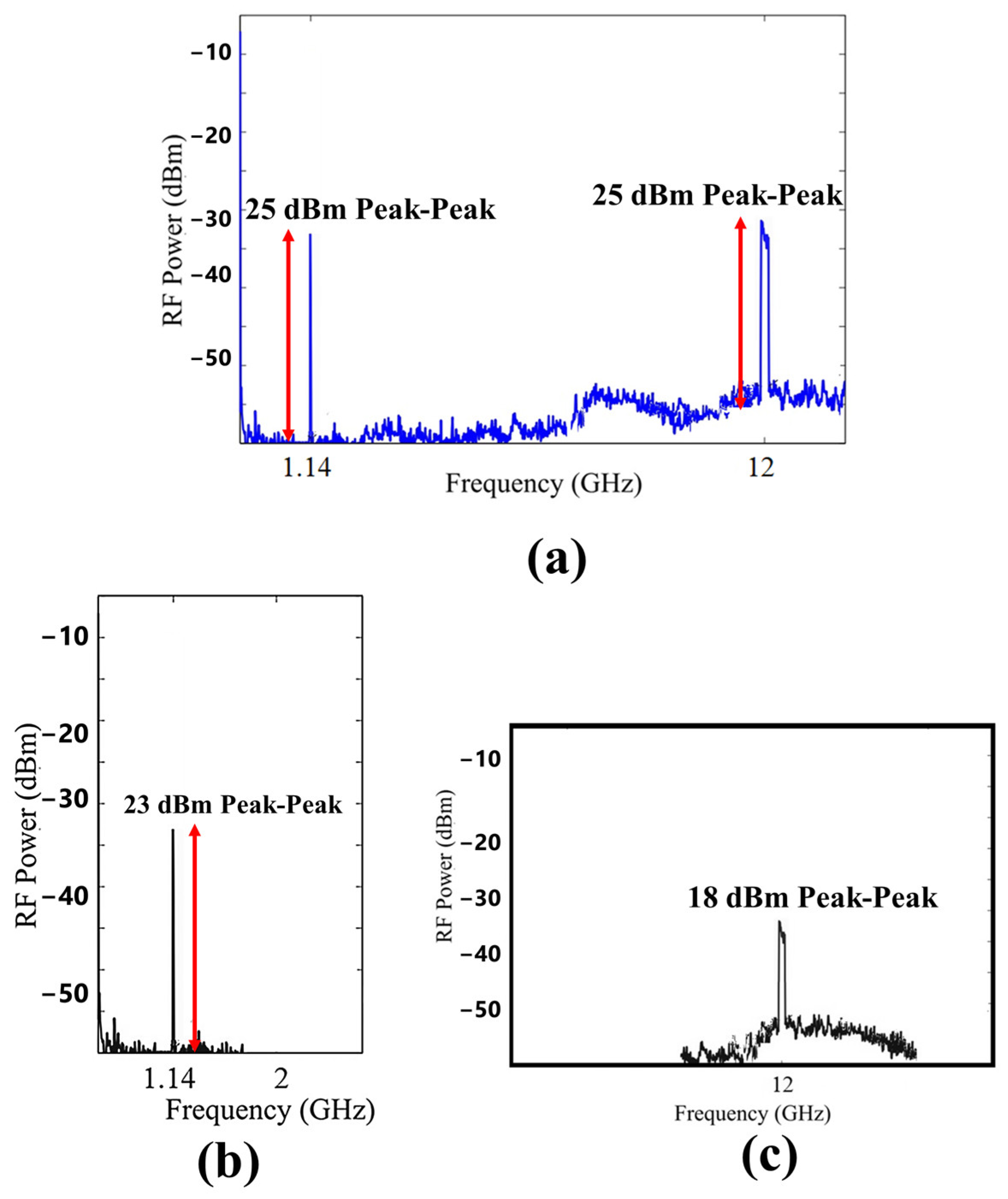
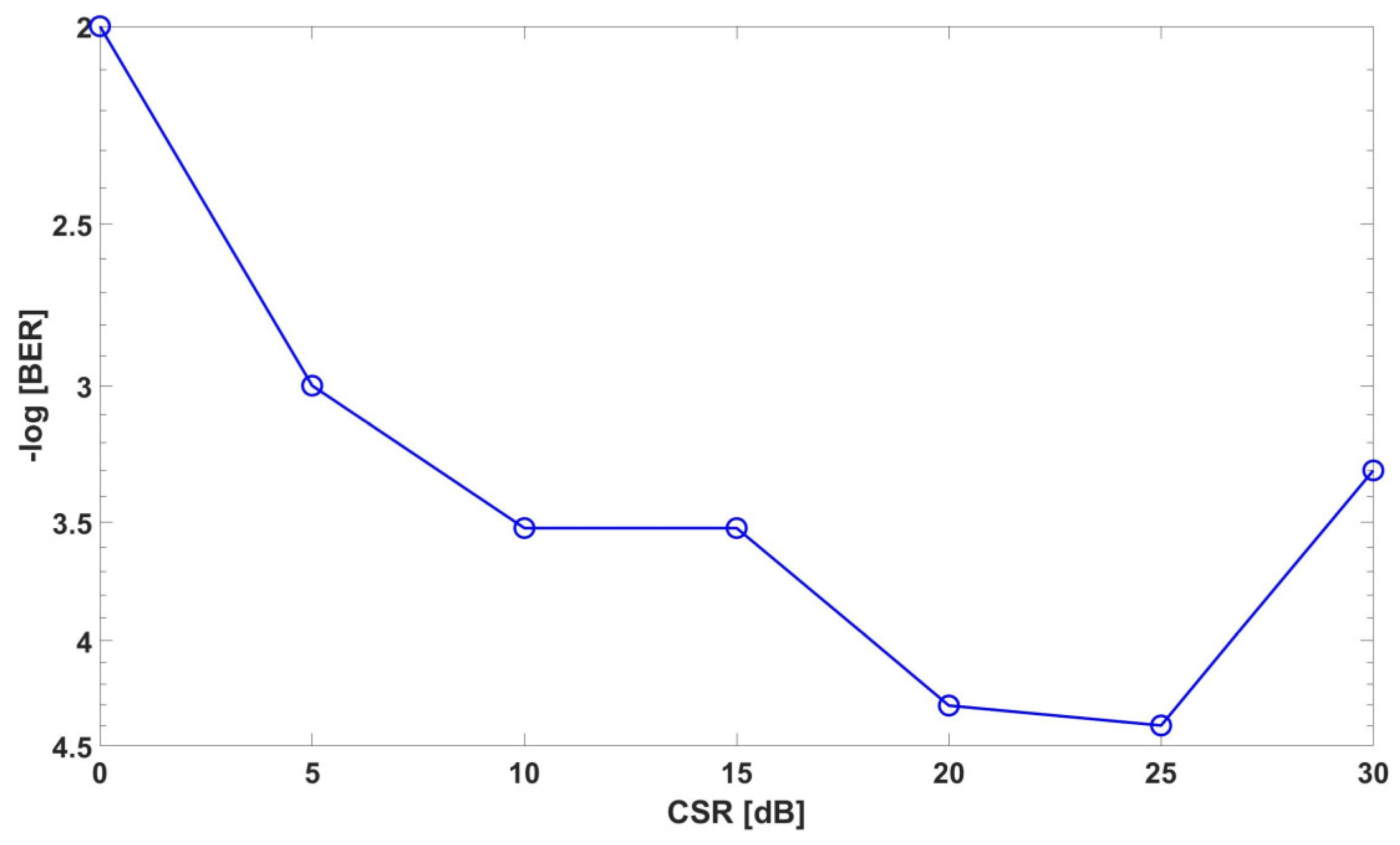
The experimental trial is assessed in terms of error vector magnitude (EVM) and Carrier Suppression Ratio (CSR).
The remainder of the paper is divided into the following sections. Section 2 discusses the Industrial Distributed Antenna System assisting 5G and 6G services followed by Section 3 which explains the experimental setup and realization. Section 4 will provide the results. Section 5 discusses the future prospects and challenges, while Section 6 concludes the paper.

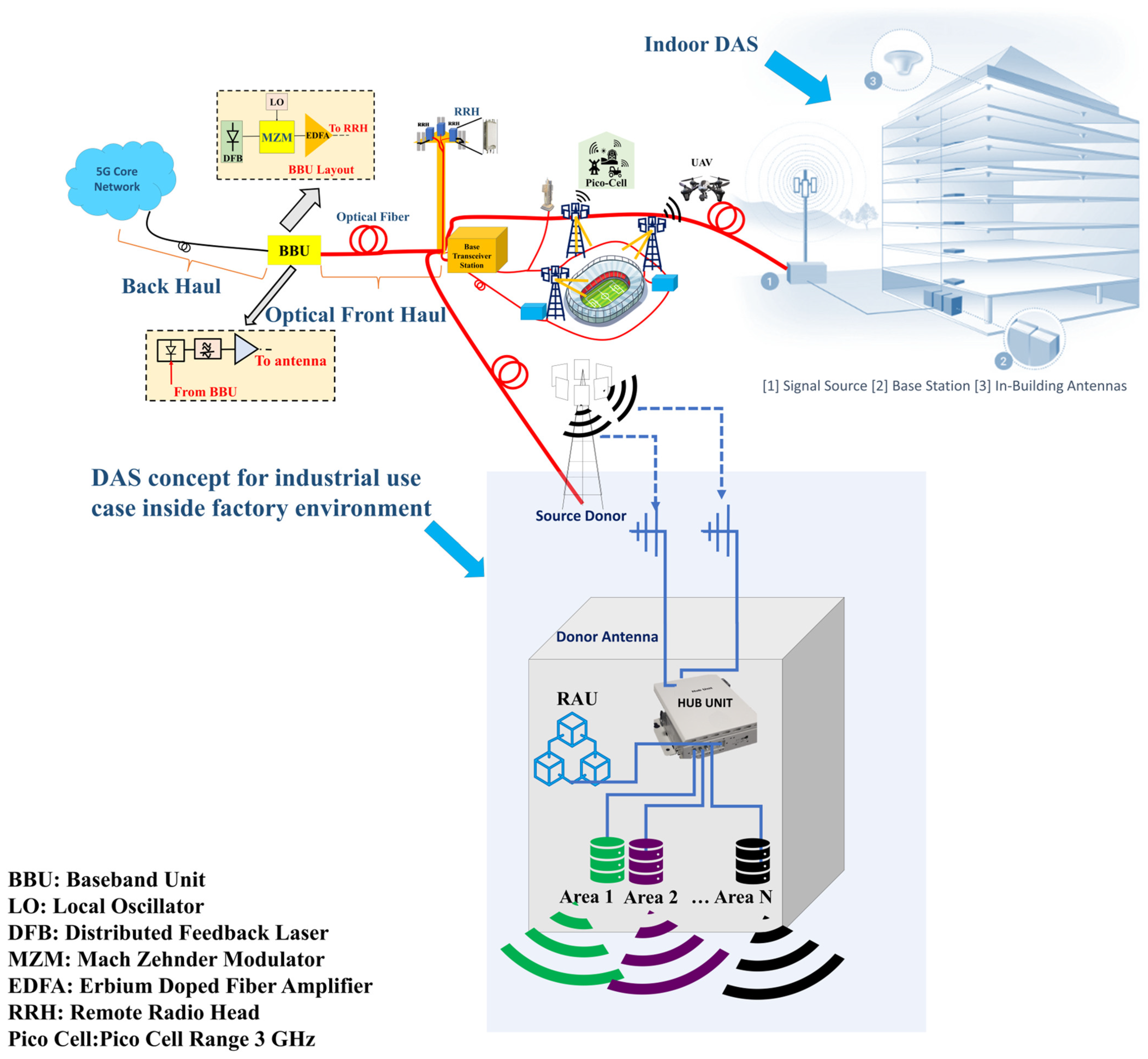
2. Industrial Distributed Antenna System Assisting 5G and 6G Services

The industrial distributed antenna system, also known as IDAS, includes a remote antenna unit (RAU), main hub unit (MHU) and over-the-air (OTA) interface for wireless links to provide a remote unit (RU) via mmWave and/or a THz-based bridge for mobile fronthaul [8]. The RoF-DAS network is depicted in Figure 2. First, the intermediate frequencies (IF), which include f I F 1 for mmWave and f I F 2 for THz processing, are injected into the Mach Zehnder modulator for optical transmission through a fibre. The optical coupler separates to the respective RAUs for mmWave and THz processing. At the 5G RAU, the 5G signal is photo-detected by the PIN photodiode and is then amplified by an in-built trans-impedance amplifier. The 5G-RAU signal detected by the optical transceiver is reshaped and retimed in the electrical-driven mixer-based phase-locked loop clock receiver equipment, and is further used to convert the IF signal to a 5G signal in the desired frequency band.
Both signals undergo filtering to be sure that the 5G RAU and 6G RAU signals go to their respective sections for post-processing. An electrical mixer driven by an RF local oscillator (LO) can be used for frequency up-conversion from the IF-to-mmWave band. At 6G-RAU, the optical signal is passed through an optical band-pass filter (OBPF), which is then combined with the output of the laser operating at λ 2 nm, and then the combined signal is detected by the uni-travelling carrier photodiode (UTC-PD). The 6G-RAU includes an optical LO operating at λ2 and a UTC-PD for optical heterodyne mixing. The photo-mixing generates various optical beat components, among which λ 2 and λ R S B are used, as it maximizes the throughput of the received signal.

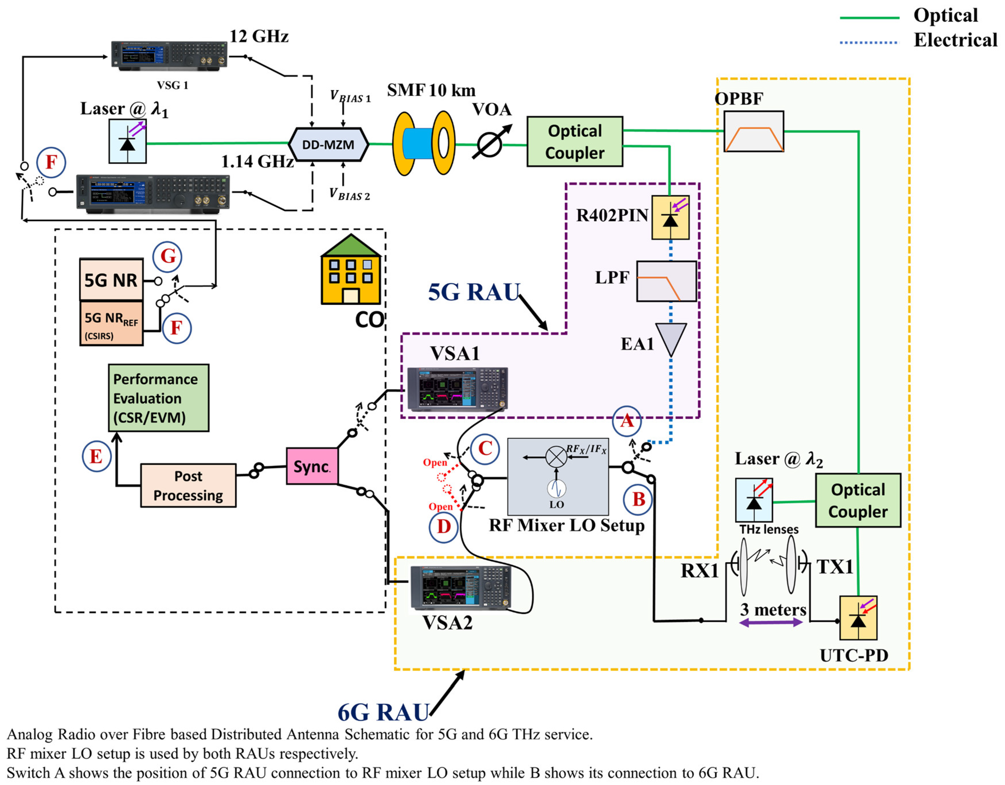
3. Experimental Setup of A-RoF Based DAS

To show the experimental realization of the A-RoF-based DAS methodology, Figure 3 shows the proposed system that has been explored utilizing an industrial use-case scenario. The experimental setup is divided into the following steps:

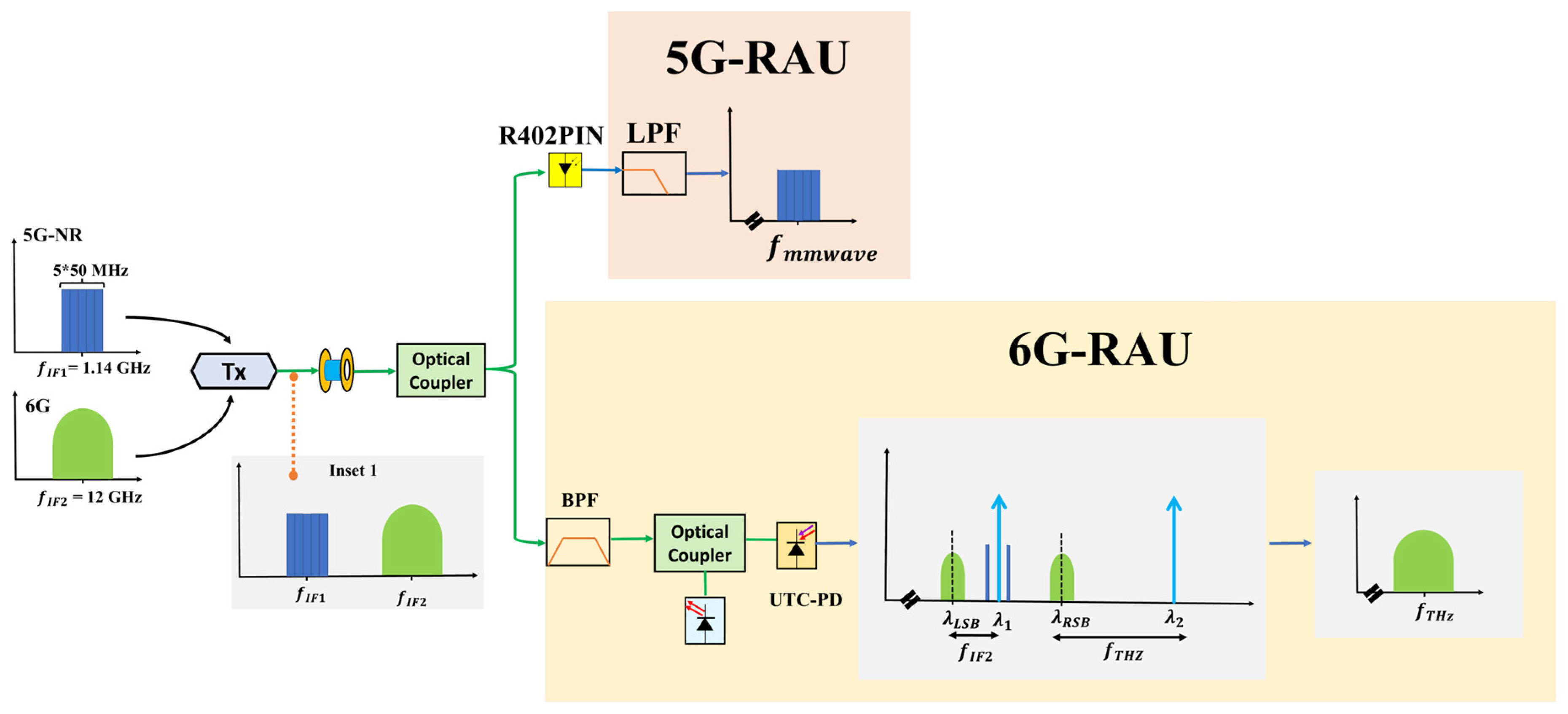
3.1. 5G and 6G Signals Generation

For signal synthesis, two vector signal generators were used consisting of Keysight M950/8194 series for the 5G and 6G signal, respectively. The 5G-new radio (NR) waveform with a frequency allocation (FA) of 50 MHz bandwidth was emulated using the 5G Toolbox available in MATLAB, followed by the uploading of this signal to Keysight M9502A. The generated signal was allocated five bands of equal FAs bandwidth, accounting for a total of 250 MHz, centred at an intermediate frequency f I F 1 of 1.14 GHz. We emulated a 256 QAM modulated signal to an intermediate frequency f I F 2 of 12 GHz for a 6G trial. The baud rate was initially set to 12 Gbaud to check the efficacy of the 6G communications.

3.2. Optical Link

The RF coupler mixed the two generated waves, which were then introduced into a dual-drive Mach-Zehnder modulator (Thor Labs LNP4216) operating at 1310 nm. The combined RF signal power was set at approximately 10 dBm. The optical link consists of a single-mode fibre (SMF) with a length of 10 km, followed by the variable optical attenuator (VOA) that incorporates the optical coupler to achieve the cascade architecture [33]. Instead of using an optical coupler, a Diplexer (DPX) could also be used as DPX has an additional advantage in that it is frequency selective and will divide the signals accordingly. The optical wave was then divided into two separate routes, one towards the 5G remote antenna unit and one towards the 6G-RAU.

3.3. 5G/6G RAUs and Postprocessing

At the 5G RAU, the 5G signal is photo detected by the PIN photodiode (R402PIN ~8 GHz) and then amplified by an in-built trans-impedance amplifier. A low-pass filter (LPF) is used to filter out the THz signal for the 5G RAU. The 5G-RAU signal detected by the optical transceiver is reshaped and retimed in the electrical-driven mixer-based phase-locked loop clock receiver equipment, being further used to convert the IF signal to a 5G signal in the desired frequency band.
At the 6G-RAU, the optical signal passes through an OBPF, which has the bandwidth and filter-edge roll-off equivalent to ∼1.5 nm and ∼12 dB/GHz. The output of the OBPF is combined with the output of the laser, i.e., LO operating at 1315 nm followed by its detection by the UTC-PD. The 6G-RAU includes an optical LO operating at λ2 and a UTC-PD for optical heterodyne mixing. An electrical mixer driven by LO can be used to frequency up-convert a signal from the IF to the required band. Note that the additional OBPF and LPF were used to filter any unwanted frequencies from the 5G and 6G RAUs.
In this proof of concept, IF-over-Fibre link experiments were conducted, where the 5G signal at the IF band was transported in an analog waveform.

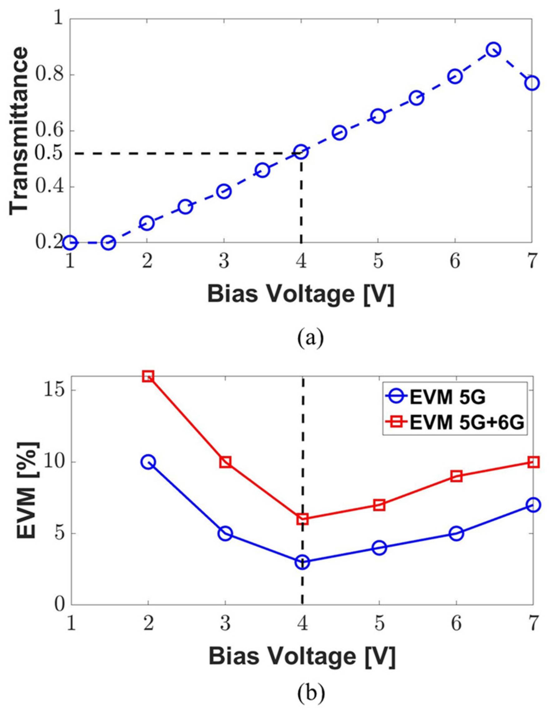
3.4. Peak Point Optimization

The following equation describes the transfer function of a MZM with driving voltages:
S M Z M = E o u t E I N = cos ( V ( t ) 2 ) cos ( ω L O t )
Here, E o u t and E I N represents the MZM output and input electromagnetic field, respectively, while V ( t ) represents the phase difference between the branches of MZM, which is given as:
V ( t ) = V ( t ) V π π
where V ( t ) represents the driven voltage and V π represents the half-wave voltage of the MZM. The biased voltage must be set to a value equal to 0.5 V π + n V π to function in the quadrature point of the MZM.
Figure 4 shows the MZM peak point optimization performance. The performance of the 5G and 6G signals varied significantly as the bias voltage moved through the interference cycle (from null to peak). To marginally increase the performance of the 6G signal at the expense of the 5G signal EVM, where we placed the MZM in the experiment at the quadrature point. The simultaneous transmission of both the 5G and 6G signal degrades the SNR of the 6G signal, which leads to an overall increase in the EVM of the system. The 6G RAU has a THz receiver that consists of a horn antenna constituting DAS. The ainfoinc horn antenna has a directional gain of approximately 20 dBi, allowing it to transmit the signal to the THz receiver through the 3 m long wireless channel. The emitted signal from the horn antenna is received from the other side of the horn antenna connected with the Vector Signal Analyzer through a frequency mixer chain which already has an inbuilt downconverter to bring the signal to its IF band for post-processing. This RF mixer LO setup can be switched between 5G RAU and 6G RAU as required. In post-processing, offset recompenses are then achieved, which includes synchronization in the time and frequency domain. To ensure tight time synchronization, a mechanism developed in [34] was employed that relies on fast detection via the first path of arrival in the channel impulse response. Table 1 summarises the values of the different components that were employed in this study.

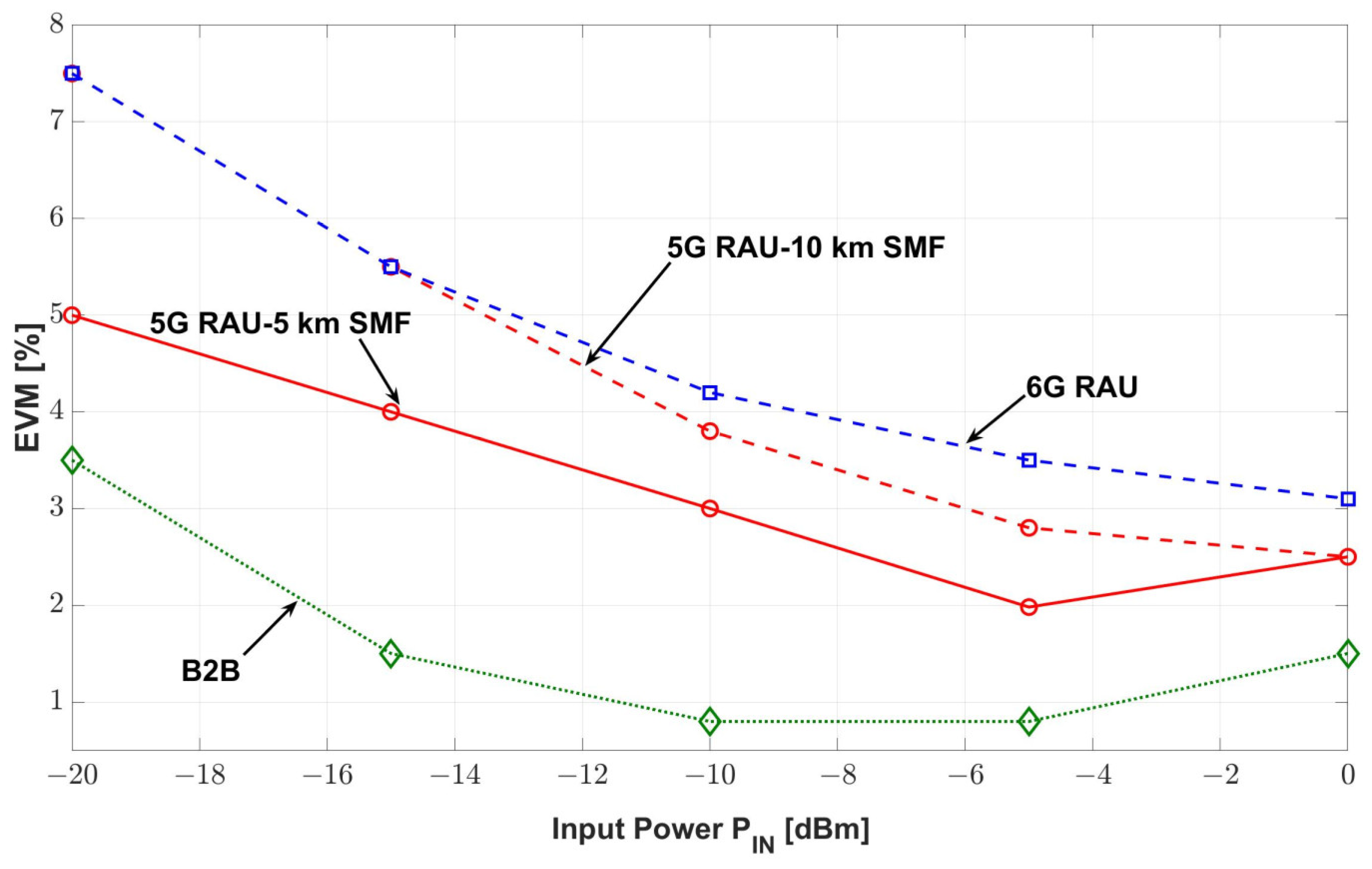
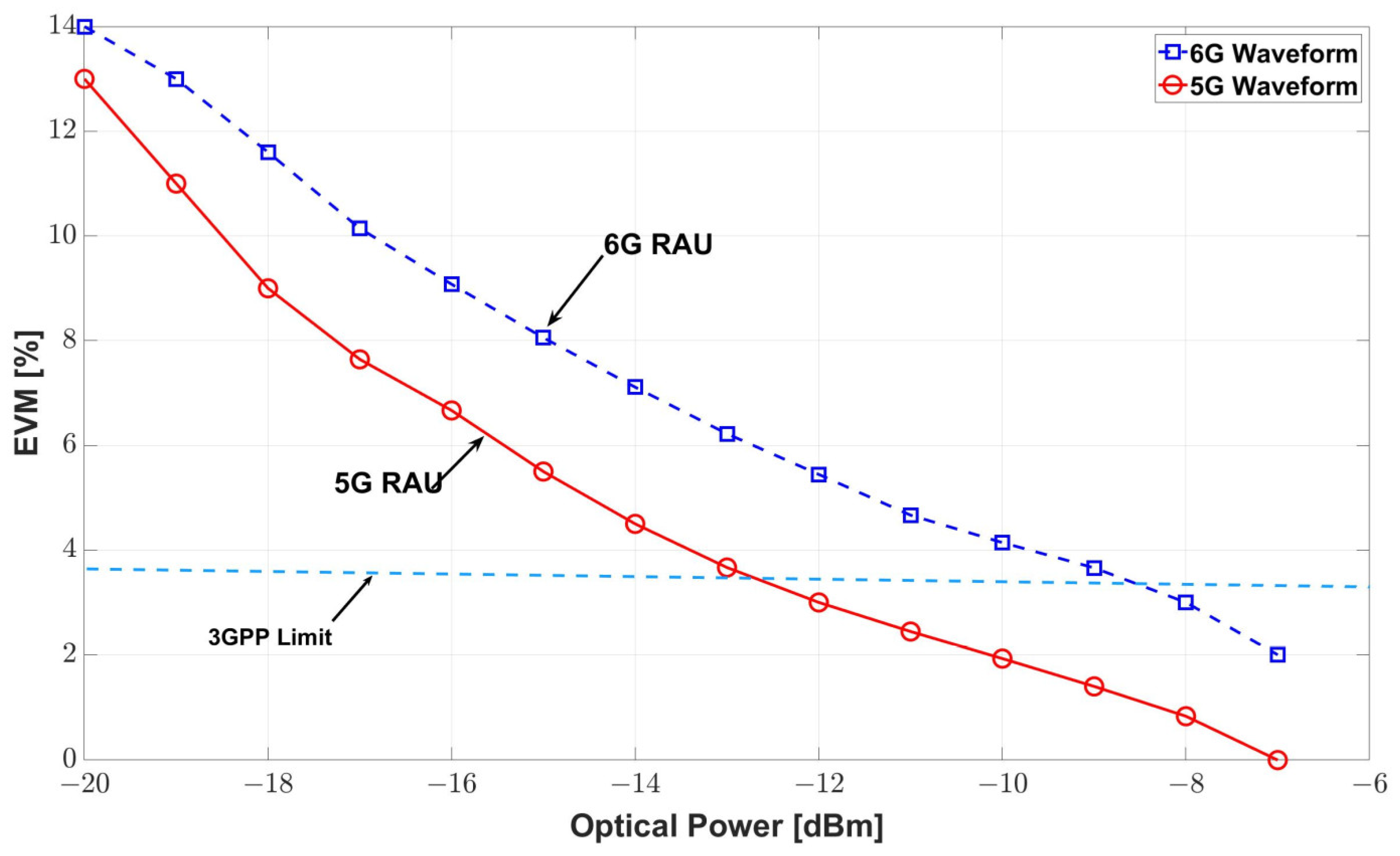
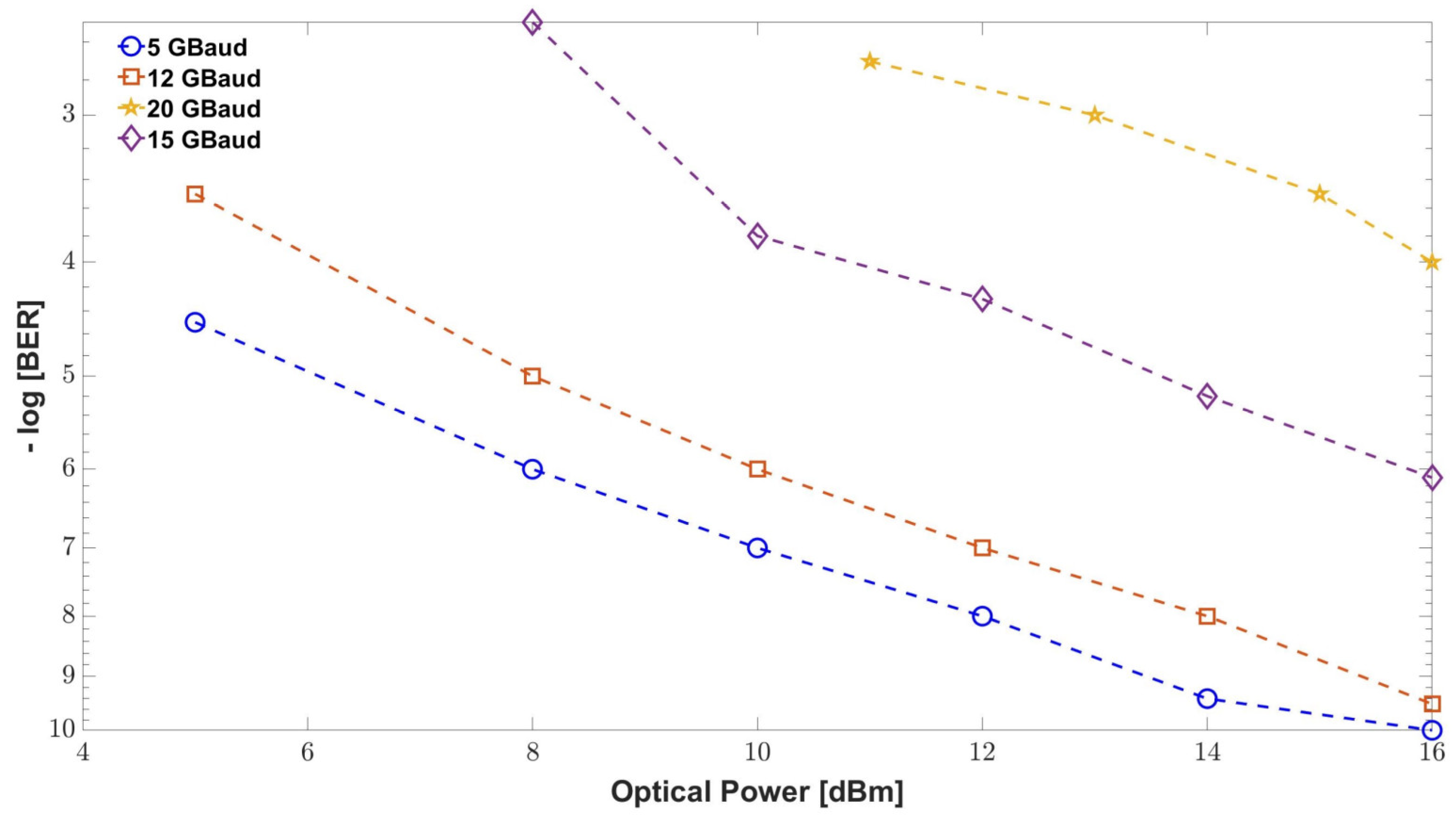
4. Experimental Results

The results of the experimental bench are discussed. The 3GPP has a standardized performance metric EVM and CSR. The EVM is defined as [35]:
E V M   ( % ) = 1 M m = 1 M | S m S 0 , m | 2 1 M m = 1 M | S m | 2
Here, M represents the constellation symbols, S m gives the constellation’s real symbol associated with the symbol “ m ” and S 0 , m denotes the real symbol linked with S m .
The other performance metric used is Carrier Suppression Ratio (CSR). It is the measure of the RF carrier leakage relative to the modulated output signal. It is defined as [36]:
C S R d B = 10   log 10 [ P C a r r i e r   L e a k a g e P R F   o u t p u t ] M e a s u r e d
where P C a r r i e r   L e a k a g e implies the measured carrier leakage power and P R F   o u t p u t represents the measured RF output power.
Figure 5 shows the spectra of the waveforms that are seen just after the 10 km fibre length. The 5G and 6G THz receiver, consisting of a frequency mixer chain, performs down-conversion, converting the signal to the IF band of f I F 1 and f I F 2 , respectively, for performance processing. Simplifying the system configuration and management of the IF bands is particularly advantageous when compared to coherent systems that require THz mixers and local oscillators to be frequency/phase-locked to the oscillator at the central unit [37]. Similarly, the 5G RAU and 6G RAU outputs are visualized to see the filtering process and, in the case of the 6G RAU, the wireless reception. It can be seen that the 5G RAU received at the VSA1 is received at 1.14 GHz and it is received with a slight degradation in the spectra. However, the 6G RAU signal received over a 3 m wireless distance with a 12 GHz carrier is received with a degradation of 18 dB, peak to peak, compared to 25 dB, peak to peak, at the photodiodes output.
Figure 6 shows the impact of the carrier suppression ratio (CSR) in dB after 10 km of SMF and a 3 m wireless distance. The BER performance was substantially boosted as the CSR increased from 0 to 20 dB. The BER started to degrade when the CSR was further increased to compensate for the EDFA issues such as noise. One of the reasons for this behavior is that higher input power can lead to nonlinearities in the transmission system, which can result in the generation of additional sidebands. Another reason is that higher input power can lead to increased noise in the system, which can also contribute to an increase in the CSR.
Figure 7 represents the error vector magnitude of the 5/6G waves received at the respective RAUs. To see the effect of the different components of the link on the EVM, we show a back-to-back (B2B) scenario in which there was no fibre length and the modulator was directly connected to the receiver via a patch cord fibre. The other comparison is between 5 km and 10 km in length, which clearly shows to what extent the fibre impacts the EVM degradation. It can be observed that, in general, the received 6G waveform has larger degradation, which is visible due to its higher EVM %. At a high RF input power range, the EVM goes below the threshold of 3.5% set by the 3GPP [38], while the 5G waveform undergoes less degradation. It can be seen that the dynamic range of allowed RF input power for a 6G signal is 10 dB, while the dynamic range for a 5G waveform signal is 18 dB. The higher degradation of the 6G signal is due to the losses that occur over the air interface. Similarly, the received optical power vs. EVM for the two waveforms is also shown in Figure 8. The results clarify that both of the waveforms can co-exist simultaneously, and the trial confirms that the dynamic range of operating the two waveforms is acceptable.

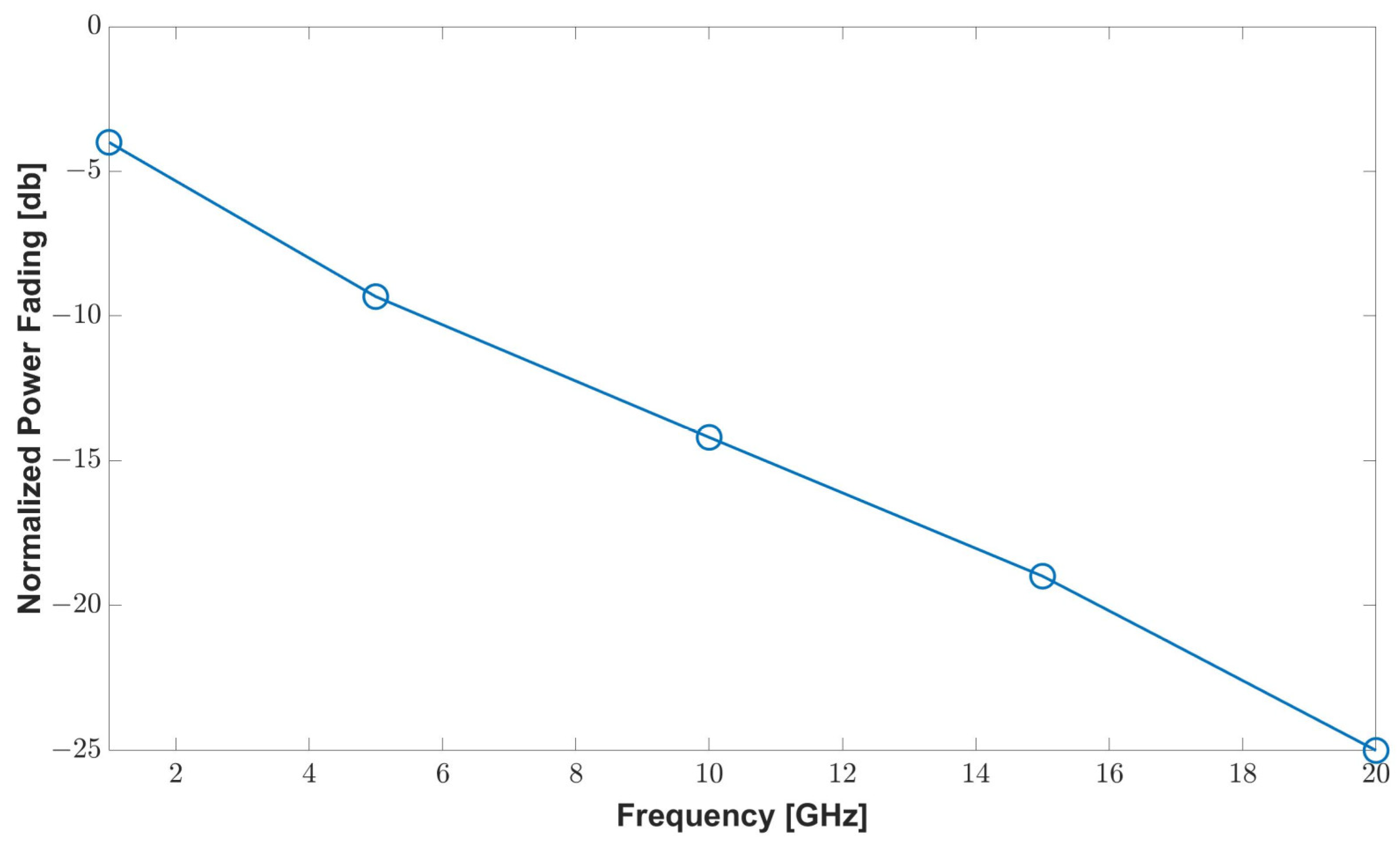
Effect of Chromatic Dispersion and Power Fading

One of the main effects of chromatic dispersion (CD) in RoF systems is that it can cause the modulated RF signal to spread out over a larger portion of the fiber, leading to a reduction in the signal strength and an increase in the bit error rate. This is because the different wavelengths of light that make up the modulated RF signal will travel at slightly different speeds through the fiber due to the changes in the refractive index of the fiber with wavelength. As a result, the different wavelengths will arrive at the destination at slightly different times, leading to a spreading out of the signal.
It is known that CD is the result of the combination of waveguide dispersion D w and material dispersion D M and is generally represented as [39,40]:
C D = β ω 2 2 π c
where β represents the part of the phase constant that is affected by the optical carrier frequency ω . In general, the value of chromatic dispersion for SMF at 1550 nm is 17 ps/(nm.km).
The optical signal created by the laser’s modulation of the RF signal travels via an optical fibre and, as a result, each band experiences a distinct phase rotation as a result of the optical fibre’s chromatic dispersion. The injected RF signal’s strength is amplified by a constant that relies on the phase mismatch of the two optical sidebands before the optical signal at the SSMF’s output beats in a PD and retrieves it by heterodyne detection. This condition that occurs due to chromatic dispersion is known as power fading.
The power constant K P F for power fading is represented as follows [41,42]:
K P F = cos 2 ( ϑ L S B ϑ R S B )
where ϑ L S B represents the rotation in the phase induced by the CD of the fibre in the left sideband, while ϑ R S B represents the one induced in the right sideband.
Both chromatic dispersion and power fading can have a significant impact on the performance of 5G and 6G fiber systems, including those using THz and distributed antenna systems (DAS). In order to ensure reliable and high-quality communication, it is important to carefully design and engineer the RoF-based DAS system. This may involve using specialized fibers with lower dispersion characteristics, or using techniques such as wavelength division multiplexing (WDM) to reduce the impact of dispersion on the signal. Other strategies to mitigate the effects of chromatic dispersion in RoF systems may include using repeaters or amplifiers to boost the signal strength, or using error-correction techniques to mitigate the impact of errors on the transmission. The utilization of Digital Predistortion (DPD) for counteracting these nonlinearities can be a good approach [21].
In the proposed system, the length of the SMF in the system being discussed is 10 km, which is a relatively smaller length, and the frequency of the intermediate frequency carrier was relatively low, i.e., 1.14 GHz. As a result, the effects of power fading were not noticeable. Additionally, the use of zero-chirp Mach-Zehnder modulators (MZM) eliminated inter-mixing and the generation of second-order intermodulation distortion (IMD2). This was also true for the sub-terahertz 6G system, where the use of only a single sideband in fibre-wireless transmission eliminated the effects of RF fading. Figure 9 shows below the power fading for the range of 1 GHz to 20 GHz.
Similarly, we characterized the 6G THz system performance by increasing the Gbaud rate test for the 6G signal by increasing its baud rate with respect to optical power and saw the behaviour in terms of BER, as shown in Figure 10. To prevent 5G and 6G bands from interfering with each other, the f I F 2 of the 6G signal was increased by 250 MHz for every 2 GB increment in the baud rate.
In addition, the performance of the proposed system is summarized and compared in Table 2 with the state-of-the-art relevant method of the 5G RoF system, which was evidenced in the previous work of the authors in [16] and others in [43], with the same link length and other settings. The wireless reception can be further enhanced by using wireless signal detection using the techniques discussed in [44].

5. Challenges and Future Prospects

The proposed fibre wireless distributed antenna system would have some higher complexity for RAU because it contains more photonic components than the MHU, including a laser source, DPX, amplifiers, filters and photodiode. The limitations of the experimental setting forced the 6G THz link’s wireless transmission distance to be 3 m with a clear deficit of 7 dB. THz amplifiers could be used to make up for the additional losses brought on by the longer wireless range [11]. For instance, a 20 dB amplifier gain will provide a 10× increase in distance (i.e., 30 m).
Additionally, the linearization mechanism will be required at some point to further improve the performance of this system. This means that receiving feedback signals from the BS to the RAU is crucial. This is because the feedback link may be nonlinear; in fact, it may be just as nonlinear as the Fi-Wi-DAS link. The present solutions available only take into account the non-idealities of the RoF link, which is first compensated for by utilising a post distorter and known training signal from the RAU. Following that, the downlink RoF link that has already been compensated may be used as a feedback connection for the compensation. However, a plausible solution can be achieved by moving the complex signal processing at the Central Office/Base Transmit Station as a potential feedback situation (CO-BTS).
Similarly, in the coming years, the 6G era will face a massive surge of applications requiring extremely low latency, ultra-high reliability, high capacity, hyper-connectivity, scalable, ubiquitous, and distributed communication paradigms. A good number of research articles are readily available in the literature detailing the envisioned 6G architecture and the possible disruptive technologies. To meet the stringent requirements of the 6G mobile technology and for provisioning the 6G transport over the access network, the passive optical network (PON) has been considered as a cost-effective solution. In such cases, PON-based DAS systems should be evaluated.
For high-speed computing, we also need to fulfil the low latency requirement. Although multilevel pulse amplitude modulation (PAM) can be used to expand the capacity of components with limited bandwidth, it has strict criteria for driving electronics and photonics in terms of linearity and noise tolerance. For this kind of short-reach application, on-off keying (OOK) merits further investigation. In this study, 222 Gbaud OOK transmission over a 120-m single-mode fibre (SMF) was accomplished using a plasmonic modulator with a high-speed 2:1 selection; however, the configuration also included two erbium-doped fibre amplifiers (EDFA) [45]. Additionally, the power split ratio of the analog optical link to realize the shared infrastructure, leading to further cost/energy reduction, should be addressed.

6. Conclusions

In this article, we experimentally demonstrated an industrial-use case of a DAS network based on RoF that can accommodate both a fifth-generation millimetre wave and sixth-generation terahertz services. The single-carrier modulated 6G signal using 256-QAM and a 5G new radio signal is experimentally broadcasted across a single mode fibre optic link of 10 km. Additionally, the 6G signal is received through a 3 m wireless medium at the 6G RAU. The limitations of the experimental setting forced the 6G THz link’s wireless transmission distance to be 3 m with a net loss of 7 dBm in power. The performance is evaluated in terms of EVM and CSR. The dynamic range of the allowed RF input power for a 6G signal is 10 dB, while the dynamic range for a 5G waveform signal is 18 dB. Similarly, the enhancement of CSR resulted in a significant improvement in the BER. Additionally, as there are many photonic components used in this experiment, photonic integration is a crucial tool for the coexistence of the 5G and 6G services, which can be realized using silicon photonics. Although silicon photonics are an expensive solution, real-time digital signal processing-based solutions can be used to simplify some of the integration issues.

Author Contributions

Conceptualization, M.U.H.; methodology, M.U.H.; software, M.U.H.; validation, M.U.H. and G.M.; formal analysis, M.U.H.; investigation, M.U.H. and G.M.; resources, M.U.H.; data curation, writing—original draft preparation, M.U.H. and G.M.; supervision, M.U.H. All authors have read and agreed to the published version of the manuscript.

Funding

This research received no external funding.

Institutional Review Board Statement

Not applicable.

Data Availability Statement

The data presented in this study are available on request from the corresponding author.

Acknowledgments

Authors would like to thank School of Engineering, Ulster University for the provision of financial support in realizing the experimental testbed.

Conflicts of Interest

The authors declare no conflict of interest.

References

  1. Nanni, J.; Polleux, J.-L.; Algani, C.; Rusticelli, S.; Perini, F.; Tartarini, G. VCSEL-based radio-over-G652 fibre system for short-/medium-range MFH solutions. J. Light. Technol. 2018, 36, 4430–4437. [Google Scholar] [CrossRef]
  2. Samon, B. Setting the Scene for 5G: Opportunities and Challenges; Report D-PREF-BB.5G; International Telecommunications Union: Geneva, Switzerland, 2018. [Google Scholar]
  3. Littmann, D.; Wilson, P.; Wigginton, C.; Hann, B.; Fritz, J. 5G: The Chance to Lead for a Decade; Deloitte Develop. LLC: Oakland, CA, USA, 2018. [Google Scholar]
  4. Tian, Y.; Lee, K.-L.; Lim, C.; Nirmalathas, A. 60 GHz Analog Radio-Over-Fiber Fronthaul Investigations. J. Light. Technol. 2017, 35, 4304–4310. [Google Scholar] [CrossRef]
  5. Tariq, F.; Khandaker, M.R.A.; Wong, K.-K.; Imran, M.A.; Bennis, M.; Debbah, M. A Speculative Study on 6G. IEEE Wirel. Commun. 2020, 27, 118–125. [Google Scholar] [CrossRef]
  6. Tataria, H.; Shafi, M.; Molisch, A.F.; Dohler, M.; Sjoland, H.; Tufvesson, F. 6G Wireless Systems: Vision, Requirements, Challenges, Insights, and Opportunities. Proc. IEEE 2021, 109, 1166–1199. [Google Scholar] [CrossRef]
  7. International Telecommunications Union. IMT Traffic Estimates for the Years 2020 to 2030; Report ITU-R M.2370-0; International Telecommunications Union: Geneva, Switzerland, 2015. [Google Scholar]
  8. Kim, J.; Sung, M.; Cho, S.-H.; Won, Y.-J.; Lim, B.-C.; Pyun, S.-Y.; Lee, J.-K.; Lee, J.H. MIMO-supporting Radio-Over-Fiber system and its application in mmWave-based indoor 5G mobile network. J. Light. Technol. 2020, 38, 101–111. [Google Scholar] [CrossRef]
  9. Sung, M.; Kim, J.; Kim, E.-S.; Cho, S.-H.; Won, Y.-J.; Lim, B.-C.; Pyun, S.-Y.; Lee, H.; Lee, J.K.; Lee, J.H. RoF-based radio access network for 5G mobile communication systems in 28-GHz millimeter-wave. J. Light. Technol. 2020, 38, 409–420. [Google Scholar] [CrossRef]
  10. Hermelo, M.F.; Shih, P.-T.; Steeg, M.; Ng’Oma, A.; Stöhr, A. Spectral efficient 64-QAM-OFDM terahertz communication link. Opt. Express 2017, 25, 19360–19370. [Google Scholar] [CrossRef]
  11. Harter, T.; Füllner, C.; Kemal, J.N.; Ummethala, S.; Steinmann, J.L.; Brosi, M.; Hesler, J.L.; Bründermann, E.; Müller, A.-S.; Freude, W.; et al. Generalized Kramers–Kronig receiver for coherent terahertz communications. Nat. Photonics 2020, 14, 601–606. [Google Scholar] [CrossRef]
  12. Li, X.; Yu, J.; Wang, K.; Zhou, W.; Zhang, J. Photonics-aided 2 × 2 MIMO wireless terahertz-wave signal transmission system with optical polarization multiplexing. Opt. Express 2017, 25, 33236–33242. [Google Scholar] [CrossRef]
  13. Jia, S.; Zhang, L.; Wang, S.; Li, W.; Qiao, M.; Lu, Z.; Idrees, N.M.; Pang, X.; Hu, H.; Zhang, X.; et al. 2 × 300 Gbit/s Line Rate PS-64QAM-OFDM THz Photonic-Wireless Transmission. J. Light. Technol. 2020, 38, 4715–4721. [Google Scholar] [CrossRef]
  14. Beas, J.; Castanon, G.; Aldaya, I.; Aragon-Zavala, A.; Campuzano, G. Millimeter-Wave Frequency Radio over Fiber Systems: A Survey. IEEE Commun. Surv. Tutor. 2013, 15, 1593–1619. [Google Scholar] [CrossRef]
  15. Perez, G.O.; Lopez, D.L.; Hernandez, J.A. 5G new radio fronthaul network design for eCPRI-IEEE 802.1CM and extreme latency percentiles. IEEE Access 2019, 7, 82218–82230. [Google Scholar] [CrossRef]
  16. Hadi, M.U.; Song, J.; Soman, S.K.O.; Rahimian, A.; Cheema, A.A. Experimental Evaluation of Hybrid Fibre–Wireless System for 5G Networks. Telecom 2022, 3, 218–233. [Google Scholar] [CrossRef]
  17. Zhang, X.; Zhu, R.; Shen, D.; Liu, T. Linearization Technologies for Broadband Radio-Over-Fiber Transmission Systems. Photonics 2014, 1, 455–472. [Google Scholar] [CrossRef]
  18. Vieira, L.; Gomes, N.J.; Nkansah, A.; van Dijk, F. Behavioral Modeling of Radio-Overfibre Links Using Memory Polynomials. In Proceedings of the 2010 IEEE Topical Meeting on Microwave Photonics (MWP), Montreal, QC, Canada, 5–9 October 2010; pp. 85–88. [Google Scholar]
  19. Hadi, M.U.; Awais, M.; Raza, M.; Ashraf, M.I.; Song, J. Experimental Demonstration and Performance Enhancement of 5G NR Multiband Radio over Fiber System Using Optimized Digital Predistortion. Appl. Sci. 2021, 11, 11624. [Google Scholar] [CrossRef]
  20. Nanni, J.; Giovannini, A.; Hadi, M.U.; Lenzi, E.; Rusticelli, S.; Wayth, R.; Perini, F.; Monari, J.; Tartarini, G. Controlling Rayleigh-Backscattering-Induced Distortion in Radio Over Fibre Systems for Radioastronomic Applications. J. Light. Technol. 2020, 38, 5393–5405. [Google Scholar] [CrossRef]
  21. Hadi, M.; Awais, M.; Raza, M.; Khurshid, K.; Jung, H. Neural Network DPD for Aggrandizing SM-VCSEL-SSMF-Based Radio over Fiber Link Performance. Photonics 2021, 8, 19. [Google Scholar] [CrossRef]
  22. Liu, S.; Alfadhli, Y.M.; Shen, S.; Tian, H.; Chang, G.K. Mitigation of Multi-User Access Impairments in 5G A-RoF-Based mobile-Fronthaul Utilizing Machine Learning for an Artificial Neural Network Nonlinear Equalizer. In Proceedings of the Optical Fibre Communication Conference, San Diego, CA, USA, 11–15 March 2018. [Google Scholar]
  23. Pereira, L.; Lopes, C.; Borges, R.; Lima, E.; Ferreira, A.; Abreu, M.; Mendes, L.; Arismar Cerqueira, S., Jr. Implementation of a multiband 5G NR fiber-wireless system using analog radio over fiber technology. Opt. Commun. 2020, 474, 126112. [Google Scholar] [CrossRef]
  24. Nanni, J.; Fernandez, L.; Hadi, M.U.; Viana, C.; Tegegne, Z.G.; Polleux, J.L.; Tartarini, G. Effect of system dynamics in multi-channel 850 nm VCSEL-based radio-over-G.652 fibre. Electron. Lett. 2020, 56, 385–388. [Google Scholar] [CrossRef]
  25. Hadi, M.U.; Jung, H.; Ghaffar, S.; Traverso, P.A.; Tartarini, G. Optimized digital radio over fiber system for medium range communication. Opt. Commun. 2019, 443, 177–185. [Google Scholar] [CrossRef]
  26. Xu, M.; Lu, F.; Wang, J.; Cheng, L.; Guidotti, D.; Chang, G.-K. Key technologies for next-generation digital RoF mobile fron-thaul with statistical data compression and multiband modulation. J. Light. Technol. 2017, 35, 3671–3679. [Google Scholar] [CrossRef]
  27. Yang, Y.; Lim, C.; Nirmalathas, A. Experimental Demonstration of Multi-Service Hybrid Fiber-Radio System Using Digitized RF-Over-Fiber Technique. J. Light. Technol. 2011, 29, 2131–2137. [Google Scholar] [CrossRef]
  28. Hadi, M.U. Mitigation of nonlinearities in analog radio over fiber links using machine learning approach. ICT Express 2021, 7, 253–258. [Google Scholar] [CrossRef]
  29. Wu, C.-Y.; Li, H.; Van Kerrebrouck, J.; Breyne, L.; Bogaert, L.; Demeester, P.; Torfs, G. Real-Time $4\times 3.5$ Gbps Sigma Delta Radio-over-Fiber for a Low-Cost 5G C-RAN Downlink. In Proceedings of the European Conference on Optical Communication (ECOC), Roma, Italy, 23–27 September 2018; pp. 1–3. [Google Scholar] [CrossRef]
  30. Li, H.; Bauwelinck, J.; Demeester, P.; Torfs, G.; Verplaetse, M.; Verbist, J.; Van Kerrebrouck, J.; Breyne, L.; Wu, C.-Y.; Bogaert, L.; et al. Real-Time 100-GS/s Sigma-Delta Modulator for All-Digital Radio-Over-Fiber Transmission. J. Light. Technol. 2020, 38, 386–393. [Google Scholar] [CrossRef] [Green Version]
  31. Liu, X.; Zeng, H.; Chand, N.; Effenberger, F. Efficient Mobile Fronthaul via DSP-Based Channel Aggregation. J. Light. Technol. 2015, 34, 1556–1564. [Google Scholar] [CrossRef]
  32. GPP TS 38.101-2; User Equipment (UE) Radio Transmission and Reception; Part 2: Range 2 Standalone. Version 17.4.0; ETSI: Sophia Antipolis, France, December 2021.
  33. Kim, E.-S.; Sung, M.; Lee, J.H.; Lee, J.K.; Cho, S.-H.; Kim, J. Coverage extension of indoor 5G network using RoF-based dis-tributed antenna system. IEEE Access 2020, 8, 194992–194999. [Google Scholar] [CrossRef]
  34. Hadi, M.U.; Jacobsen, T.; Abreu, R.; Kolding, T. Performance Analysis and Enhancements for Multipath Scenarios. In Proceedings of the 2021 IEEE Lat-in-American Conference on Communications (LATINCOM), Santo Domingo, Dominican Republic, 17–19 November 2021; pp. 1–5. [Google Scholar]
  35. Hadi, M.U.; Nanni, J.; Polleux, J.-L.; Traverso, P.A.; Tartarini, G. Direct digital predistortion technique for the compensation of laser chirp and fiber dispersion in long haul radio over fiber links. Opt. Quantum Electron. 2019, 51, 205. [Google Scholar] [CrossRef]
  36. Moon, S.-R.; Sung, M.; Kim, E.-S.; Lee, J.K.; Cho, S.-H.; Kim, J. RoF-based indoor distributed antenna system that can simul-taneously support 5G mmWave and 6G terahertz services. Opt. Express 2022, 30, 1521–1533. [Google Scholar] [CrossRef]
  37. Moon, S.-R.; Han, S.; Yoo, S.; Park, H.; Lee, W.-K.; Lee, J.K.; Park, J.; Yu, K.; Cho, S.-H.; Kim, J. Demonstration of photon-ics-aided terahertz wireless transmission system with using silicon photonics circuit. Opt. Express 2020, 28, 23397–23408. [Google Scholar] [CrossRef]
  38. 3GPP TR 38.901; Study on Channel Model for Frequencies from 0.5 to 100 GHz. Version 16.1.0; ETSI: Sophia Antipolis, France, 2019.
  39. Agrawal, G.P. Fiber-Optic Communication Systems. In Fiber-Optic Communication Systems, 4th ed.; Wiley: Hoboken, NJ, USA, 2012. [Google Scholar] [CrossRef]
  40. Bogatyrev, V.; Bubnov, M.; Dianov, E.; Kurkov, A.; Mamyshev, P.; Prokhorov, A.; Rumyantsev, S.; Semenov, V.; Semenov, S.; Sysoliatin, A.; et al. A single-mode fiber with chromatic dispersion varying along the length. J. Light. Technol. 1991, 9, 561–566. [Google Scholar] [CrossRef] [Green Version]
  41. Meslener, G. Chromatic dispersion induced distortion of modulated monochromatic light employing direct detection. IEEE J. Quantum Electron. 1984, 20, 1208–1216. [Google Scholar] [CrossRef]
  42. Havstad, S.; Sahin, A.; Adamczyk, O.; Xie, Y.; Willner, A. Distance-independent microwave and millimeter-wave power fading compensation using a phase diversity configuration. IEEE Photonics Technol. Lett. 2000, 12, 1052–1054. [Google Scholar] [CrossRef]
  43. Borges, R.M.; Pereira, L.A.M.; Ferreira, A.C.; Mendes, L.L.; Spadoti, D.H.; Cerqueira Sodre, A., Jr. Fifth-generation new radio fiber-wireless system for long-reach and enhanced mobile broadband scenarios. Microw. Opt. Technol. Lett. 2021, 63, 662–669. [Google Scholar] [CrossRef]
  44. Khurshid, K.; Khan, A.A.; Siddiqui, M.H.; Hadi, M.U.; Rashid, I.; Imran, M. Optimality of Linear MIMO Detection for 5G Systems via 1-Opt Local Search. J. Electr. Eng. Technol. 2021, 16, 1099–1108. [Google Scholar] [CrossRef]
  45. Heni, W.; Baeuerle, B.; Mardoyan, H.; Jorge, F.; Estaran, J.M.; Konczykowska, A.; Riet, M.; Duval, B.; Nodjiadjim, V.; Goix, M.; et al. Ultra-High-Speed 2:1 Digital Selector and Plasmonic Modulator IM/DD Transmitter Operating at 222 GBaud for Intra-Datacenter Applications. J. Light. Technol. 2020, 38, 2734–2739. [Google Scholar] [CrossRef]
Figure 1. Block diagram showing a backhaul, the baseband unit (BBU) connected to an optical front haul (OFH). The base station connects the remote radio heads (RRHs), the distributed antenna system for industrial and indoor factory use case is also shown where RoF as an OFH is connected to the RRH and then DAS via source donor and receive antennas is integrated with hub unit for wireless connectivity.
Electronics 12 00064 g001
Figure 2. Block diagram explaining the operation principle of RoF-based optical transport system of DAS network capable of supporting 5G and 6G services.
Electronics 12 00064 g002
Figure 3. RoF OFH integration system with DAS for IF carriers. A Mach-Zehnder as an external modulator is used with a single mode fibre of 10 km deployed.
Electronics 12 00064 g003
Figure 4. (a) MZM measured transmission power in the optical domain concerning bias voltage and (b) EVM with and without 6G signal for varying bias voltages.
Electronics 12 00064 g004
Figure 5. RF power vs. frequency showing (a) multiband signal of 5G after down conversion back to IF of 1.14 GHz and 6G signal at 12 GHz. (b) 5G signal at 5G RAU showing the received signal after 10 km of fibre length. (c) 6G signal at 6G RAU showing the received signal after 10 km of fibre length and 3 m wireless distance.
Electronics 12 00064 g005
Figure 6. Bit error ratio (BER) for 10 km SMF with 3 m wireless distance for CSRs.
Electronics 12 00064 g006
Figure 7. EVM vs. RF input power for 5G (B2B, 5 km and 10 km SMF length) and 6G signals at respective RAUs.
Electronics 12 00064 g007
Figure 8. EVM vs. optical power for 5G and 6G signals at respective RAUs.
Electronics 12 00064 g008
Figure 9. Power fading w.r.t frequency range covering the two intermediate frequencies.
Electronics 12 00064 g009
Figure 10. Profile of increasing baud rate for varying optical power in terms of BER.
Electronics 12 00064 g010
Table 1. Testbed link component parameters.
ParametersValues
Signal f I F 1 = 1.14 × 10 9 Hz
f I F 2 = 12 × 10 9 Hz
F/G/O—FDM signal
Modulation Data Rate = 256 QAM
Laser Type Wavelength λ 1 = 1310 nm, λ 2 = 1315 nm
Mach Zehnder Modulator
FibreSMF
Link length = 10 km
Fiber Dispersion = 16 ps ( nm . km ) 1
Attenuation = 0.32 dB ( km ) 1
PhotoreceiverR402 PIN: ,   R e s p o n s i v i t y = 0.84 A/W
FilterBandpass Filter (∼1.5 nm and ∼12 dB/GHz)
Lowpass Filter (1.14 GHz)
AntennaDirectional Gain = 20 dBi
3dB Beamwidth = 23.71 deg
Cross Pol. Isolation = 35 dB
Table 2. Summary and comparison with the relevant state of the art at RF input power of 0 dBm.
TypeEVM [%]
Proposed 5G RAU (only)2.5
Proposed 5G RAU with 6G 3.1
Fi-Wi RoF (5G only) [16]7
Fi-Wi RoF [40]4.2
Disclaimer/Publisher’s Note: The statements, opinions and data contained in all publications are solely those of the individual author(s) and contributor(s) and not of MDPI and/or the editor(s). MDPI and/or the editor(s) disclaim responsibility for any injury to people or property resulting from any ideas, methods, instructions or products referred to in the content.

