Abstract
A voltage balance control strategy based on the fuzzy adaptive PI (Proportional Integral control) is proposed to address the problem of unbalanced capacitor voltage on the DC side of cascaded H-bridge static var generators (SVG). In the control strategy, fuzzy control is introduced based on PI control. A duty ratio correction is added to all levels’ public active power duty ratios, thereby realizing the balance of DC-side voltages at all levels. A test was conducted by building a single-phase three-H-bridge unit cascaded SVG simulation platform. The results show that the DC-side voltage balance can be controlled by the voltage balance control strategy at all levels effectively. It has the advantages of a simple control structure, double closed-loop control with decoupling of the system’s current DQ, no coupling effect, a fast response speed, and high precision. The voltage balance control strategy can exert a good control effect when the system experiences a sudden voltage imbalance.
1. Introduction
Static var generators have become the focus of research in reactive power compensation at home and abroad because of their advantages of fast response speed and high reliability. With the continuous expansion of the power system scale, the cascaded H-bridge structure is widely used in the primary circuit structure of SVG because of its easy modularization, low harmonics, and fewer switching devices when the output level is the same.
The DC side capacitors of the cascaded H-bridge SVG are independent. Ideally, the DC side voltages are balanced and stable at all levels. However, under the actual operating conditions, due to the influence of the series loss, hybrid loss, and the parallel loss of the H-bridge module itself, the DC side voltage cannot reach a balanced state. Voltage imbalance will lead to the distortion output voltage waveform, increase the device’s failure, and even damage the device in severe cases. Therefore, ensuring the DC side voltage balance is the key to the reliable operation of the cascaded H-bridge SVG. In recent years, many papers have proposed the control method for the DC side voltage of the cascaded H-bridge SVG; it can be roughly divided into the hardware voltage equalizing method and the software voltage equalizing method [1,2,3,4]. In [1], a method is proposed to improve the operating range of low capacitance SVG devices under inductive conditions by using the optimal third harmonic current injection, but it does not give the derivation process of zero sequence voltage that can be used in star cascaded H-bridge SVG devices. A variable DC link algorithm based on flexible third-order harmonic injection is proposed in [2], which can give the minimum value of the DC side peak voltage under the compensation capacitive condition, and improve the utilization of the DC side voltage by increasing the modulation rate by injecting flexible third-order harmonic, but it does not give the minimum value of the DC side peak voltage under inductive working conditions. In [3], a low capacitance SVG with modular filter inductance is proposed. The thyristor controlled reactor is used to replace the fixed value reactor. By reducing the voltage drop on the reactor, the system voltage is further reduced, but it requires additional thyristor, which reduces the reliability of the system and increases the complexity of the system. In [4], under the condition of unbalanced power grid, in order to prevent excessive voltage fluctuation from triggering overvoltage protection sub harmonic, reduce the peak voltage of capacitor, and improve the reliability of system operation.
However, the most commonly used method is the additional hardware circuit method [5,6,7,8,9,10,11,12,13,14,15]. The relationship between the modulation ratio increment of the rectifier and the output voltage is proposed in [5]. On this basis, the modulation ratio is reconfigured by the fed DC voltage to adjust the DC voltage to balance. A new voltage-balancing controller is introduced in [6] for single-phase cascaded multilevel converters in a DQ coordinate. In [7], the power input from the H-bridge AC side to the DC side of the H-bridge is redistributed. Through a voltage balance controller, a duty cycle adjustment amount is added in the public duty cycle to achieve the purpose of the DC side voltage balance. Due to the inappropriate setting of duty cycle adjustment in [5,6,7], these methods can keep the DC side voltage constant. The coupling effect of the additional voltage balance controller and the double closed-loop control system is not conducive to the overall stability of system. A DC-side voltage balance control method is expounded in [8], in which neither the voltage balance controller nor the dual closed-loop control of the system has a coupling effect. Although the purpose of voltage balance is achieved, this method is realized by using n duty cycle corrections generated by n DC-side voltage balance feedback loops, which increase the voltage balance controller’s size and the equipment’s cost. In [9,10], the method in [8] is improved, in which the error between the actual value of the DC-side voltage of each H-bridge and the voltage reference value is made to pass through the PI controller, and n−1 DC-side voltage balance feedback loops are used to generate n duty cycle corrections. In [11], on the basis of the cascaded H-bridge inverter, the mathematical model of the star chain SVG is established, and a double closed-loop control system is constructed, in which the current inner loop adopts PI decoupling control and the voltage outer loop adopts hierarchical control, which solves the balance problem of capacitor voltage on the DC side. Although the structure has been simplified in [9,10,11], due to the simple design of the PI controller, it is easily affected by harsh environmental conditions such as power grid fluctuations and noise, and the model structure and parameters may change. It is difficult to obtain an ideal tracking effect by using fixed parameters to adapt to many control systems, such as control parameter changes and system disturbances. A voltage balance modular control strategy based on the combination of analog control is proposed in [12]. However, this method has the problems of weak anti-interference ability, current and voltage ripple, and needs to be transmitted through an intermediate medium.
Combined with [13,14,15], an adaptive DC link voltage balance control strategy is proposed based on fuzzy PI proposed in this paper. The current DQ decoupling of the entire system controls the output of the common active-duty cycle and reactive duty cycle, and the voltage balance controller increases the duty cycle correction of the common active-duty cycle component to achieve the effect of voltage balance. The duty cycle reconstruction mechanism is to use the n−1 DC side voltage balance feedback loop to generate n active-duty cycle corrections. Through this control strategy, the coupling effect between the voltage balance controller and the double closed loop control of the system is eliminated, the control structure is simplified, the DC side voltage is balanced, and the response speed and accuracy of the voltage balance are improved.
In this paper, the SVG is mathematically modeled; the active and reactive components of the overall duty cycle output of the system are obtained by using DQ decomposition. Then, the reasons for the voltage imbalance of the capacitor on the DC side are analyzed, and the control method in this paper is given according to the reasons, and fuzzy control is introduced on this basis, so that the accuracy and speed of the voltage balance are further improved. Finally, the reliability of the proposed method is proved by simulation experiments, and compared with the method in the previous paper, the advantages of the control method are highlighted in this paper.
2. SVG Mathematical Model
Cascaded SVG Primary Circuit Topology
This paper’s cascaded H-bridge SVG structure is shown in Figure 1, which is a three-phase three-wire system [16]. The connections of the phases are star-connected, and each step is composed of n H-bridge units in series. Udc is the DC side voltage of each H-bridge unit, which can output three different voltage values: 0, Udc, and -Udc. Usa, Usb, and Usc are, respectively, the three-phase voltages of the power grid, Isa, Isb, and Isc are, respectively, its three-phase currents, three-phase currents respectively Isa, Isb, and Isc, the three-phase voltages on the AC side of the SVG are: Uca, Ucb, and Ucc, L is the filter reactor and the equivalent inductance of the line, R is the equivalent resistance of the line.

Figure 1.
Main circuit topology.
Ideally, the mathematical expression [17] for the three-phase cascaded H-bridge SVG in the DQ coordinate system is as follows:
where Usd and Usq are the active and reactive components of the grid-side voltage, respectively; Isd and Isq are the active and reactive components of the grid current, respectively; Ucd and Ucq are the active and reactive components of the voltage on the AC side of the SVG, respectively. Equation (1) shows that through the transformation based on the DQ coordinate system, the active and reactive voltages and currents can be decoupled and controlled, and the DQ decoupling dual closed-loop control of the overall system current can be realized.
As shown in Figure 2, according to the mathematical model in the DQ coordinate system [13,18], the system achieves a constant output of public active and reactive duty cycle through the current DQ decoupling dual closed-loop control. PI controllers are used to attaining their functions in both the voltage outer loop and the current inner loop. The reference value Id* of the active current is generated by comparing the given DC side voltage reference value Uref with the average value Udca of the actual total DC side voltage through the PI controller, which is used as the input of the active component of the current inner loop. Iq* is the reactive power reference, whose value is given externally. By the control circuit shown in the figure, the active component dd and reactive component dq of the typical duty cycle can be obtained, the common duty cycle dα can be obtained through DQ inverse transformation, and finally, the drive signal of each H-bridge switch transistor can be obtained through the carrier phase-shift PWM modulation.
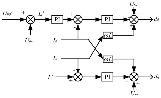
Figure 2.
Current DQ decoupled double closed-loop control.
3. SVG Control Strategy Based on the DQ Coordinate System
3.1. Cascaded SVG Primary Circuit Topology
As shown in Figure 3, the control strategy is divided into two parts: current DQ decoupling dual closed-loop control and fuzzy PI-based adaptive DC side voltage balance control.

Figure 3.
Block diagram of system control strategy.
In the DC-side voltage balance control strategy, the error between the actual voltage Udci of each H-bridge module and the command value Udca is controlled by Fuzzy-PI to obtain the modulation ratio Mi of each H-bridge module. The relationship between the modulation ratio and the duty cycle correction amount Δdi is theoretically derived. The active component dd of the typical duty cycle is superimposed to generate a new active duty cycle di′, which controls the DC-side voltage balance. In the DC side capacitor voltage control section, n active-duty cycle corrections are generated by n−1 DC-side voltage balance feedback loops, and the control structure is simplified. On the basis of PI control, fuzzy control is introduced to greatly improve the speed and accuracy of voltage balancing.
3.2. DC Side Voltage Balance Control Mechanism
When the SVG, as shown in Figure 4, is running in a stable state to explore the method of controlling the voltage balance of the DC-side, the loss of each H-bridge is represented by the equivalent resistance Ri.
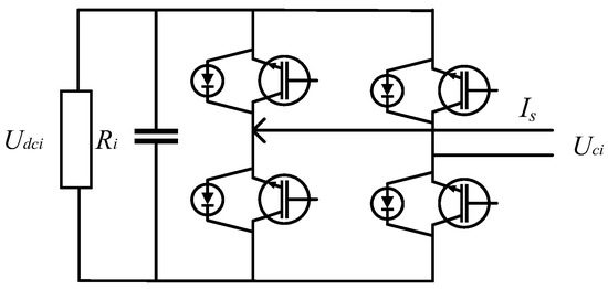
Figure 4.
Steady-state H-bridge module.
The active power input from the grid to the ith H-bridge module is:
The active power output by the ith H-bridge module on the DC-side is:
According to the linear relationship between the AC side and the DC-side voltage of the H-bridge module [19], the duty cycle di of the ith H-bridge module can be defined as:
Ignoring other system losses, the active power of the ith H-bridge module input and output is equal. By combining (2), (3), and (4), it can be deduced:
It can be seen from (5) that the current Is on the grid’s AC side remains unchanged for SVG’s cascaded structure. In the entire system, the current DQ decoupling dual closed-loop control is adopted, the output duty ratio dd of each H-bridge module is constant, and the DC side voltage is proportional to the equivalent resistance:
It can be seen from (6) that when the equivalent losses of each H-bridge are inconsistent, the DC side voltage cannot be balanced, as shown in Figure 5.

Figure 5.
Steady-steady state H-bridge module.
Where Udc1, Udc2, and Udc3 represent the output voltages of the three H-bridges respectively, the corresponding resistances are R1, R2, R3, and the resistance values are R1 > R2 > R3, and d is the public duty cycle [20]. It can be known from (4) that the vector relationship in Figure 5, can be represented by Udc1, Udc2, and Udc3. Ucd and Ucq are the active and reactive components of the AC side voltage, respectively, which can be written as follows:
Therefore, a DC voltage balance duty cycle reconstruction algorithm proposed in this paper can be shown in Figure 6.

Figure 6.
Duty cycle vector diagram.
The current DQ decoupling dual closed-loop control ensures that each H-bridge module’s output standard duty ratio di is constant and can decompose the two quantities of standard active-duty ratio and reactive power duty ratio. The DC-side voltage balance control only increases the duty cycle correction to the active-duty cycle component, while the reactive component keeps the double closed-loop constant.
According to Figure 6, the duty cycle vector relationship can be theoretically deduced:
When the system is in an unbalanced state of DC-side voltage, Δdi is the duty cycle correction amount.
According to Figure 7, the PI controller obtains the modulation ratio Mi from the error between the average value Ucda of the total DC-side voltage and the actual value Udci of the DC-side voltage of each H-bridge. KP and KI are the parameters of the PI controller, respectively, and their expressions are as follows:
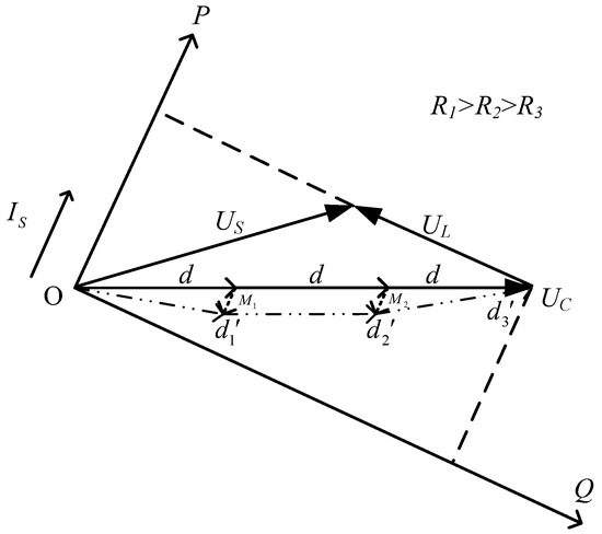
Figure 7.
Modulation ratio vector diagram.
In this paper, the SVG is composed of three H-bridge modules cascaded. The duty cycle correction amount and modulation ratio of each H-bridge module satisfy the following relationship:
It can be known from (10) n−1 DC side voltage balance feedback loops generate that n−1 duty cycle corrections. When n H-bridge modules are cascaded, all duty cycle compensations satisfy the following relationship:
As can be seen from (11), the sum of the duty cycle corrections is 0. The double closed-loop control system based on the current DQ decoupling has no coupling effect with the introduced voltage balance controller and can realize the voltage balance on the DC side of the H-bridge.
3.3. Fuzzy-PI Controller
3.3.1. Fuzzy-PI Controller
The accuracy and response speed of the traditional PI controller is challenging to meet the requirements of the voltage balance controller, so based on the PI controller, fuzzy control is used to optimize and adjust the PI parameters to make the voltage balance control more stable and effective [21,22]. The block diagram of the Fuzzy- PI controller in this paper is shown in Figure 8. Among them, E is the error value between the average value of DC- side voltage Ucda and the actual value Udci, EC is the rate of change of the error value, the quantization factors of the fuzzy controller are KE and KEC. The scale factors are Kup and Kui. Different values of the quantization factor and scale factor will affect the dynamic performance of the fuzzy controller.
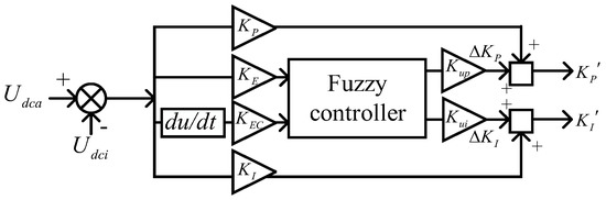
Figure 8.
Schematic diagram of a fuzzy PI controller.
KP and KI are the parameters of the PI controller, ΔKP and ΔKI are the adjustment quantities generated by the fuzzy control, and KP’ and KI’ are the adjusted PI parameters.
3.3.2. Domain of Discourse and Membership Function
The input and output fuzzy sets of the fuzzy controller are both (−6, 6), and the vague language variables are set to {NB, NM, NS, ZE, PS, PM, PB}, representing negative large, negative medium, and negative, respectively. Small, zero, positive small, positive middle, and cheerful giant, as shown in Figure 9. The quantization factors E, EC, and the scale factors Kup and Kui all obey the distribution of the triangular membership function curve.
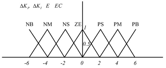
Figure 9.
Triangle membership function diagram.
3.3.3. Establishment of the Fuzzy Rule Base
The key to realizing reasonable fuzzy control is to establish proper fuzzy rules. In this paper, the fuzzy controller adjusts the PI parameters of the DC side voltage balance control system in real time, and the adjustment directions of KP and KI are different. When designing fuzzy rules, KP and KI should follow the following principles:
- (1)
- When the error E is too large, the response speed of the system will be slow, and KP should take a more significant value; at the same time, to ensure that the system does not have integral saturation and limit the necessary action, KI should take a smaller value.
- (2)
- When the error E is around medium size, KP should take a small value, and KI should take a significant discount to ensure the system response speed and control overshoot.
- (3)
- When the error E is too small, to avoid excessive error in the steady-state operation of the system and affect the control effect, KP and KI should take larger values.
According to the above principles, ΔKP and ΔKI fuzzy rules are designed as shown in Table 1 and Table 2.

Table 1.
ΔKP Fuzzy rules table.
Table 2.
ΔKI Fuzzy rules table.
3.3.4. Fuzzy Inference and Defuzzification
Fuzzy reasoning is a fuzzy control rule composed of unclear conditional statements specified according to expert experience and summary, and fuzzy logic reasoning is carried out according to the rules. The Mamdani Fuzzy Model used in this paper and its inference rules can be expressed in the following sentence:
If E is Ai and EC is Bi
then ΔKP is Ci and ΔKI is Di
Ai, Bi, Ci, and Di are the vague language sets corresponding to the universe of E, EC, ΔKP, and ΔKI, respectively. Because the actual control quantity must be an exact value, the result obtained by fuzzy inference is still an undefined quantity, which needs to be de-fuzzified. In fuzzy control, defuzzification usually adopts the area centroid method, and its reasoning formula is as follows:
Xi is the discrete elements of the fuzzy output set; A(Xi) is the membership degree corresponding to Xi, and the membership function is shown in Figure 9. μ is the exact value after defuzzification, multiplied by the scale factors Kup and Kui to obtain the values of ΔKP and ΔKI; only the same value can be accepted and recognized by the system to achieve the control effect. Therefore, the PI parameters adjusted by the fuzzy controller can be expressed as:
4. Simulation and Analysis
In this paper, a single-phase three H-bridge cascade SVG DC-side voltage control strategy simulation model is built on MATLAB/Simulink R2021b, and the feasibility and correctness of the control strategy are simulated and verified. The specific parameters are shown in Table 3.
Table 3.
MATLAB/Simulink simulation parameters.
The system simulation model is built according to the parameters presented in Table 3. The simulation conditions are set as follows: ① When the equivalent resistance of the DC-side is unbalanced, whether the DC-side voltage can be maintained in balance only based on the current DQ decoupling dual closed-loop control; ② When the current DQ decoupling dual closed-loop control based on the closed-loop power, an additional PI-based DC link voltage balance control strategy is added; ③ based on the current DQ decoupling dual closed-loop control, a different DC link voltage balance control strategy based on the fuzzy PI is added; ④ based on the fuzzy PI-based DC link voltage balance control When the voltage changes abruptly at 1 s, and it is observed whether the adaptive DC voltage balance control based on fuzzy PI can maintain the voltage constant.
Simulation conditions ①, ②, ③ set the reference voltage value to 500 V and the equivalent resistances of the three H-bridge DC sides are 150 Ω, 100 Ω, and 50 Ω, respectively. Simulation conditions ④ set the reference voltage value to 500 V, and the equivalent resistance of the DC side of the three H bridges is all 100 Ω.
Simulation conditions ① as shown in Figure 10a, when the equivalent load on the DC-side is unbalanced, the DC-side voltage balance cannot be maintained only based on the DQ decoupling dual closed-loop control. Moreover, it can be seen from the Figure 10a that the ratio of the DC side voltage of the three H-bridge modules is proportional to the resistance, which is consistent with the results of the theoretical analysis of Equation (6), so an external voltage balance controller is required to balance the DC side voltage.
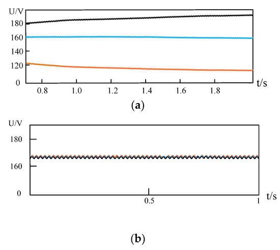
Figure 10.
Current DQ decoupled double closed-loop control. (a) When the equivalent resistance on the DC side is inconsistent, the voltage cannot be balanced. (b) When the equivalent resistance on the DC side is consistent, the voltage can be balanced.
The simulation condition is changed in Figure 10b to 100 Ω for all three H-bridge modules. The simulation results at this time are shown in Figure 10b, and the voltages of the three H-bridge modules can be maintained at a stable value, which proves that the DQ current de coupling dual closed-loop control can maintain a constant output duty cycle.
Simulation condition ② is shown in Figure 11. This paper is based on the DC-side voltage balance control strategy under PI control. It starts to act at 0 s. It can be seen from the figure that the voltage has a tendency to balance at 0.4 s, and the voltage is not entirely stable and balanced until 0.6 s. Compared with the voltage control methods of Figure 12 in [8] and Figure 13 in [9], the trend of voltage balance is shown from the DC-side voltage balance control method of [11,12] in 0.7 s. The speed and accuracy of voltage balancing are improved in this paper. However, based on the DC side voltage balance strategy under PI control, adjusting the voltage balance is long, and the effect is poor.
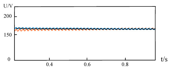
Figure 11.
Voltage value based on voltage balance strategy under PI control.
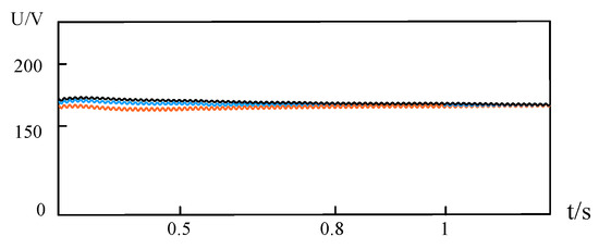
Figure 12.
Reference 8 voltage balance control strategy.
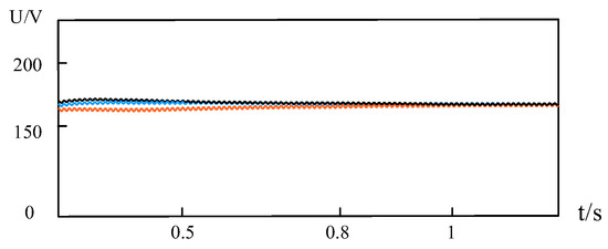
Figure 13.
Reference 9 voltage balance control strategy.
Simulation condition ③ is shown in Figure 14, based on the DC side voltage balance strategy under fuzzy PI control. It can be seen that under the control of this strategy, the DC side voltage appears to voltage balance at 0.1 s and reaches a stable state of voltage balance at 0.15 s, and can continue to maintain a stable state. The comparison and simulation experiments show that introducing fuzzy control based on PI control can quickly and effectively realize the DC side voltage balance.
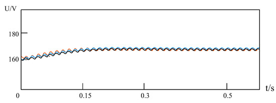
Figure 14.
Voltage balance strategy under fuzzy PI control.
To test whether the system can maintain the system voltage balance under the condition of sudden voltage unbalance based on fuzzy PI control, we carried out the simulation experiment according to the simulation condition ④, as shown in Figure 15. The results show that when the value of R1 is changed from 100 Ω to 50 Ω at 1 s, the instantaneous voltage fluctuates violently. The adaptive voltage balance control strategy based on fuzzy PI begins to work. After a short voltage imbalance, the voltage recovers after 0.1 s to a state of equilibrium. This shows that the voltage balance control strategy can exert a good control effect when the system has a sudden voltage imbalance.
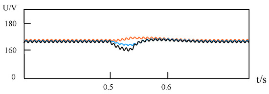
Figure 15.
Voltage mutation based on fuzzy PI control.
To test whether the voltage balance control strategy can track the new reference voltage on the DC side when the reference voltage changes, we conduct simulation experiments according to simulation condition ③, as shown in Figure 16. As can be seen from the figure, the value of the reference voltage is changed from 400 V to 500 V at 0.5 s, and the voltage fluctuates slightly, and after about 0.1 s, it stabilizes back to the set reference value. The voltage balance control strategy is proved that can effectively track the new reference voltage.
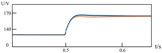
Figure 16.
Voltage balancing control strategy tracks the situation as the reference voltage changes.
5. Conclusions
In this paper, a fuzzy PI-based adaptive DC-side voltage balance control strategy is proposed, which adds an active duty-cycle correction to the public active-duty ratios of all levels to achieve the balance of the DC-side voltages at all levels. The conclusions are as follows:
- (1)
- Compared with the traditional PI control, this paper is based on the fuzzy PI control voltage balance strategy, which significantly improves the response speed and accuracy of the DC-side voltage balance controller.
- (2)
- The overall system current DQ decoupling controls the output of the public active-duty cycle and reactive duty cycle, and the voltage balance controller increases the duty cycle correction on the common active-duty cycle component to achieve the effect of voltage balance.
- (3)
- While ensuring the constant voltage of the DC side, the DC side voltage balance controller does not have a coupling effect with the dual closed-loop control of the system, and the control structure is simple and easy to implement.
Author Contributions
R.G. and Y.F. were involved in the simulation, measurement, writing and revising process of the present paper. All authors have read and agreed to the published version of the manuscript.
Funding
This research was funded by the National Natural Science Foundation of China under Grant 61561007, and in part by the Natural Science Foundation of Guangxi Province, China, under Grant 2017GXNSFAA198168.
Data Availability Statement
Not applicable.
Acknowledgments
We would like to thank the reviewers for their valuable suggestions.
Conflicts of Interest
The authors declare no conflict of interest.
References
- Rodriguez, E.; Leyva, R.; Qingxiang, L.; Townsend, C.D.; Farivar, G.G.; Ceballos, S.; Pou, J. Enhancing Inductive Operation of Low-Capacitance Cascaded H-Bridge StatComs Using Optimal Third-Harmonic Circulating Current. IEEE Trans. Power Electron. 2021, 36, 10788–10800. [Google Scholar] [CrossRef]
- Ge, X.; Gao, F. Flexible Third Harmonic Voltage Control of Low Capacitance Cascaded H-Bridge STATCOM. IEEE Trans. Power Electron. 2018, 33, 1884–1889. [Google Scholar] [CrossRef]
- Farivar, G.; Townsend, C.; Pou, J.; Hredzak, B. Low-Capacitance StatCom With Modular Inductive Filter. IEEE Trans. Power Electron. 2019, 34, 3192–3203. [Google Scholar] [CrossRef]
- Xia, L.; Ma, C.; Rong, D.; Lu, D. DC voltage control of small capacitance cascade STATCOM under imbalance. Power Electron. Technol. 2021, 55, 32–35. [Google Scholar]
- Tao, X.; Li, Y.; Sun, M. A novel voltage balance method for cascaded H-bridge rectifier. In Proceedings of the 2010 IEEE Vehicle Power and Propulsion Conference, Lille, France, 1–3 September 2010; pp. 1–5. [Google Scholar]
- She, X.; Huang, A.Q.; Wang, G.; Zhao, T.; Wang, F.; Yao, W. A new voltage-balancing controller in cascaded multilevel converters. In Proceedings of the 2011 IEEE Energy Conversion Congress and Exposition, Phoenix, AZ, USA, 17–22 September 2011; pp. 177–184. [Google Scholar]
- Tao, X.; Li, Y.; Sun, M. A new method for DC bus voltage balance control of H-bridge cascaded PWM rectifier. J. Electrotech. Technol. 2011, 26, 85–90, 105. [Google Scholar]
- Han, C.; Huang, A.Q.; Liu, Y.; Chen, B. A generalized control strategy of per-phase DC voltage balancing for cascaded multilevel converter-based STATCOM. In Proceedings of the 2007 IEEE Power Electronics Specialists Conference, Orlando, FL, USA, 17–21 June 2007; pp. 1746–1752. [Google Scholar]
- Zhao, T.; Wang, G.; Bhattacharya, S.; Huang, A.Q. Voltage and power balance control for a cascaded H-bridge converter-based solid-state transformer. IEEE Trans. Power Electron. 2013, 28, 1523–1532. [Google Scholar] [CrossRef]
- Yang, D.; Wu, N.; Yin, L.; Lu, Z. Natural Frame Control of Single-Phase Cascaded H-Bridge Multilevel Converter Based on Fictive-Phases Construction. IEEE Trans. Ind. Electron. 2018, 65, 3848–3857. [Google Scholar] [CrossRef]
- Liu, X.; Zhi, Z.; An, X.; Chen, Z. Research on control strategy of cascaded H-bridge SVG. Electr. Autom. 2019, 41, 4–7. [Google Scholar]
- Lu, Y.; Wu, C.; Zheng, Y.; Ju, Y. DC-side voltage balance control strategy of cascaded H-bridge rectifier. Electron. Des. Eng. 2022, 30, 75–81. [Google Scholar] [CrossRef]
- Zhu, H. Control Strategy for Voltage and Power Sharing of Cascaded H-Bridge Solid-State Transformers; Xiangtan University: Xiangtan, China, 2018. [Google Scholar]
- Bisht, N.; Das, A. A Circuit Topology of Cascaded H-Bridge STATCOM to Operate With Multiple Faulty Bypassed Cells. IEEE Trans. Ind. Appl. 2021, 57, 5345–5355. [Google Scholar] [CrossRef]
- Liu, B.; Song, W.; Li, Y.; Zhan, B. Performance Improvement of DC Capacitor Voltage Balancing Control for Cascaded H-Bridge Multilevel Converters. IEEE Trans. Power Electron. 2021, 36, 3354–3366. [Google Scholar] [CrossRef]
- Li, L.; Lu, X.; Ji, H.; Li, Z. Control method for DC side voltage balance of cascaded H-bridge SVG. J. Electrotech. Technol. 2016, 31, 1–7. [Google Scholar]
- Pan, H.; Zhu, H.; Xiao, Z.; Zhu, M.; Long, H.; Liu, Y. A novel DC voltage and reactive power balance control strategy for cascaded H-bridge rectifiers. Chin. J. Electr. Eng. 2017, 37, 3565–3573, +3685. [Google Scholar]
- Liu, D.; Li, W.; Hao, J.; Zhou, Z.; Zhang, L. Multi-level static var generator control based on feedforward decoupling. J. Beihua Univ. (Nat. Sci. Ed.) 2017, 18, 129–134. [Google Scholar]
- Xiang, L.; Jian, W.; Xiaojie, Y.; Kun, W. An improved proportional pulse compensation strategy for DC voltage balance of cascaded H-bridge rectifier. In Proceedings of the 2016 IEEE Energy Conversion Congress and Exposition (ECCE), Milwaukee, WI, USA, 18–22 September 2016; pp. 1–6. [Google Scholar]
- Allehyani, M.F.; Abuagreb, M.; Johnson, B.K. The Effect of Frequency Droop Damping on System Parameters and Battery Sizing During Load Change Condition. In Proceedings of the 2022 International Conference on Electrical, Computer and Energy Technologies (ICECET), Prague, Czech Republic, 20–22 July 2022; pp. 1–5. [Google Scholar] [CrossRef]
- Sain, C.; Banerjee, A.; Kumar Biswas, P.; Sudhakar Babu, T.; Dragicevic, T. Updated PSO optimized fuzzy-PI controlled buck type multi-phase inverter-based PMSM drive with an over-current protection scheme. IET Electr. Power Appl. 2020, 14, 2331–2339. [Google Scholar] [CrossRef]
- Yuan, Y.; Chen, X.; Lan, M. Fuzzy PI control strategy23 for output voltage balance of cascaded H-bridge rectifiers. J. Electr. Power Syst. Autom. 2020, 32, 116–122. [Google Scholar]
Disclaimer/Publisher’s Note: The statements, opinions and data contained in all publications are solely those of the individual author(s) and contributor(s) and not of MDPI and/or the editor(s). MDPI and/or the editor(s) disclaim responsibility for any injury to people or property resulting from any ideas, methods, instructions or products referred to in the content. |
© 2022 by the authors. Licensee MDPI, Basel, Switzerland. This article is an open access article distributed under the terms and conditions of the Creative Commons Attribution (CC BY) license (https://creativecommons.org/licenses/by/4.0/).