
Array Antenna for Wireless Access Points and Futuristic Healthcare Devices


Abstract
:1. Introduction
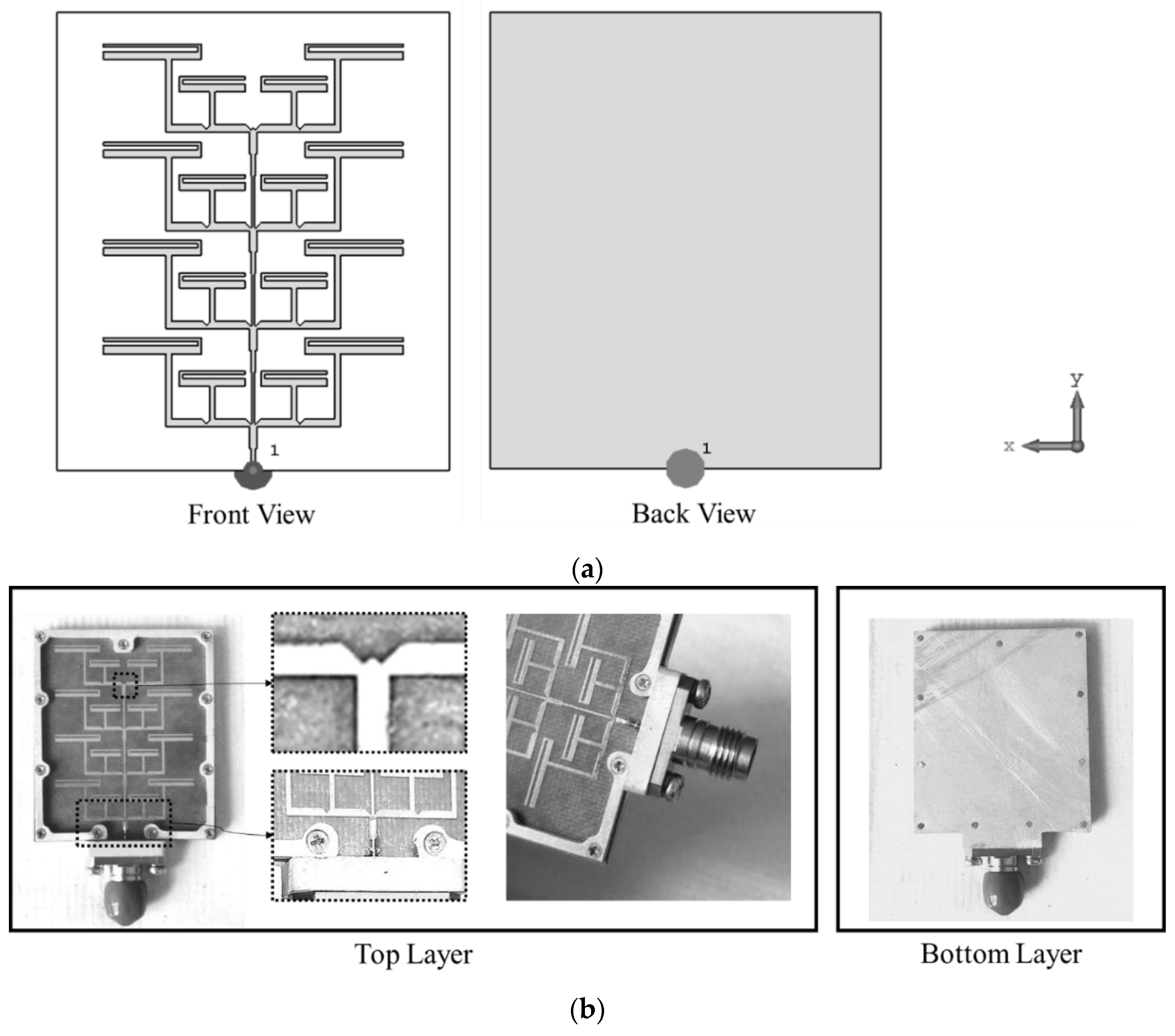
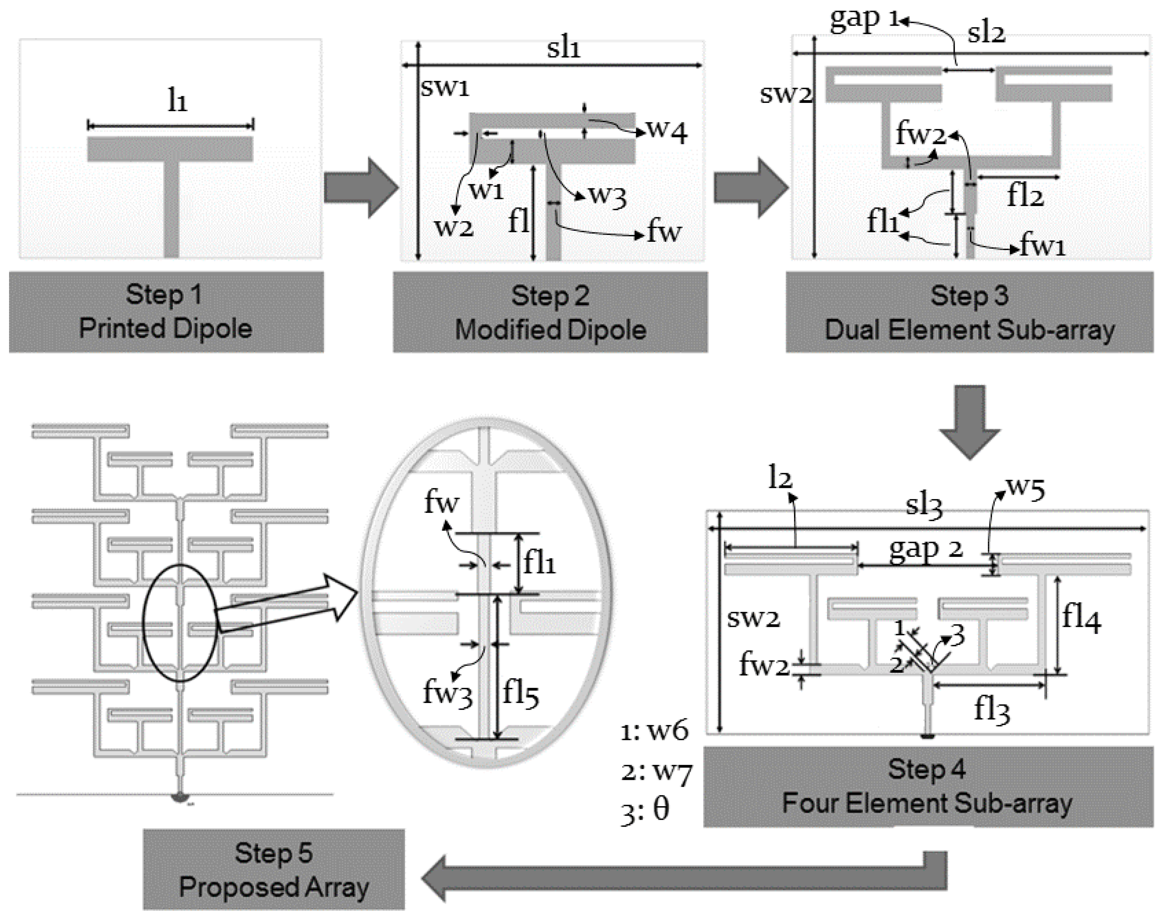
2. Antenna Design
3. Simulation and Experimental Results
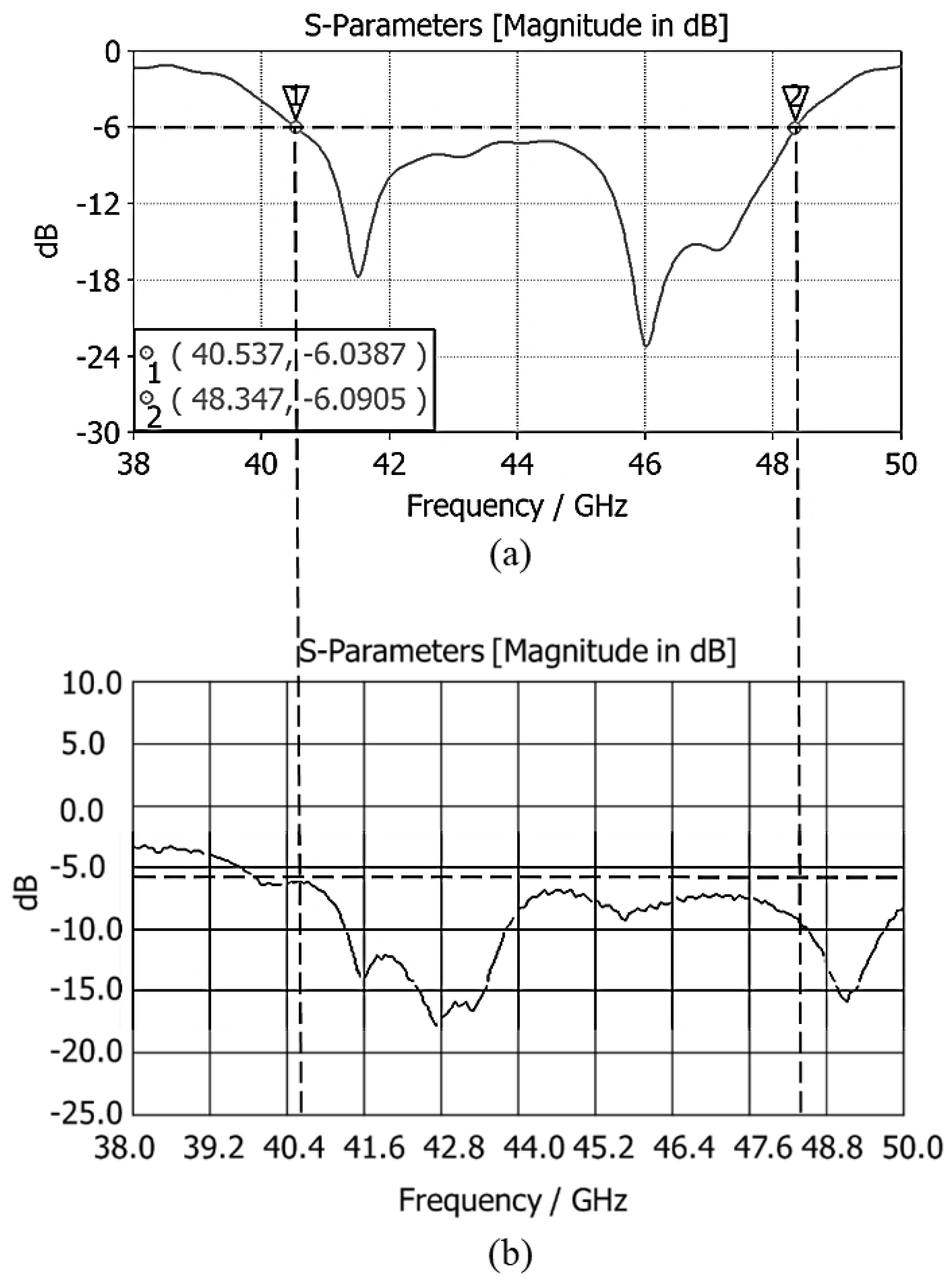
3.1. S-Parameters
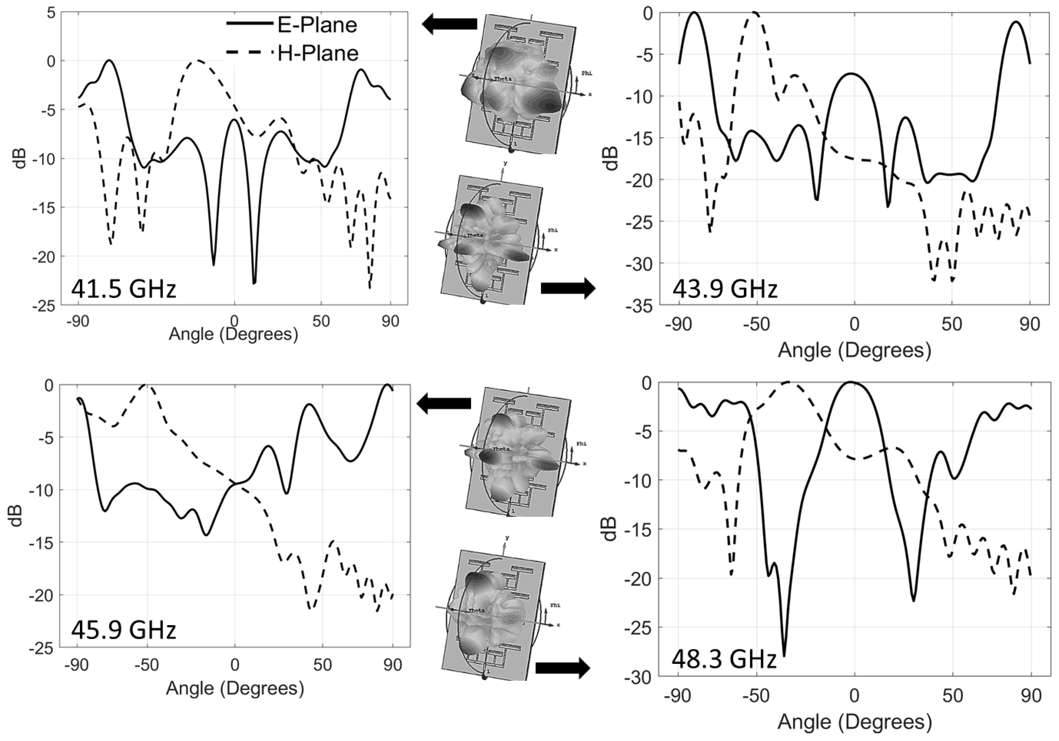
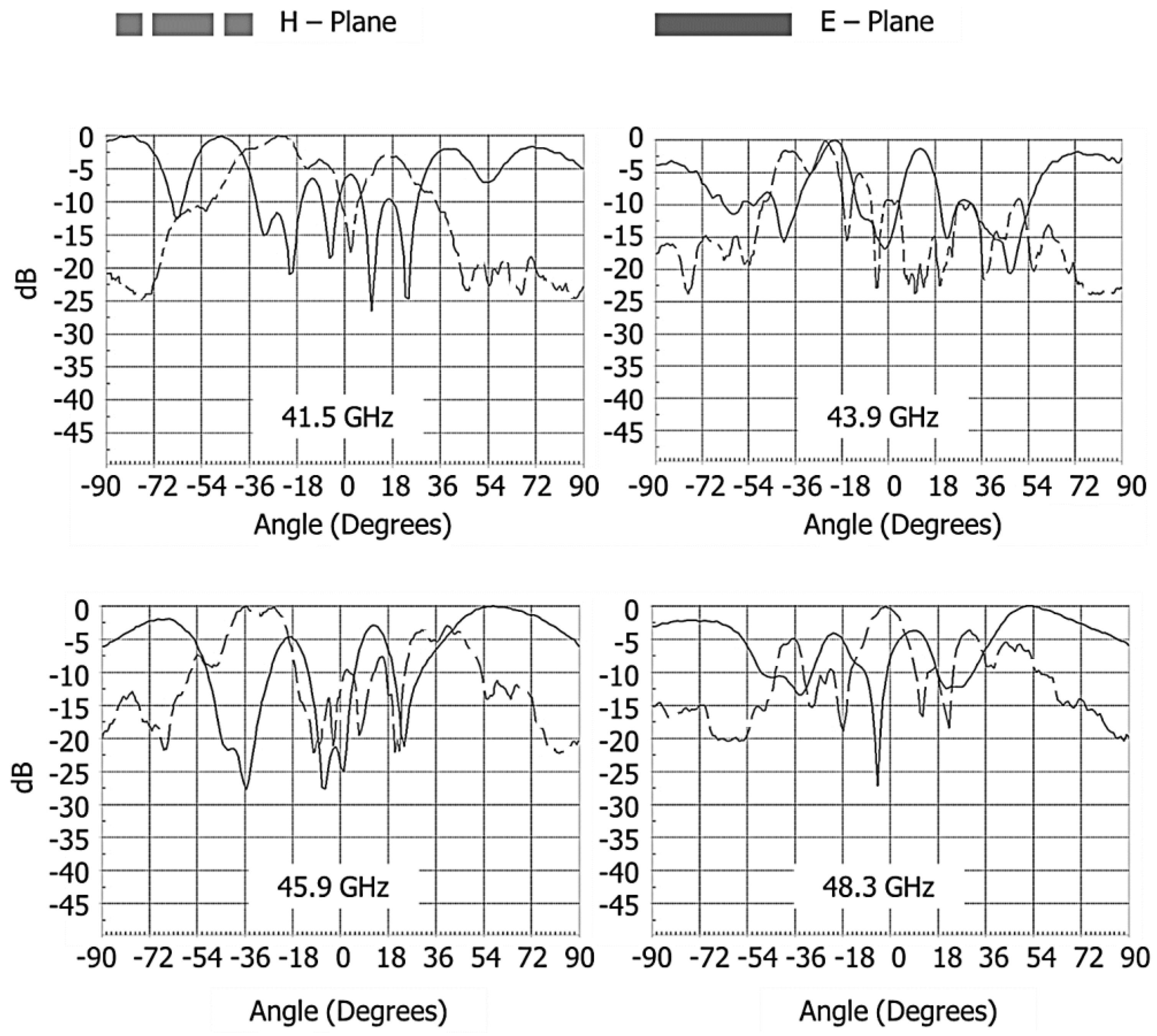
3.2. Radiation Performance
3.3. Antenna Gain
3.4. Antenna Efficiency
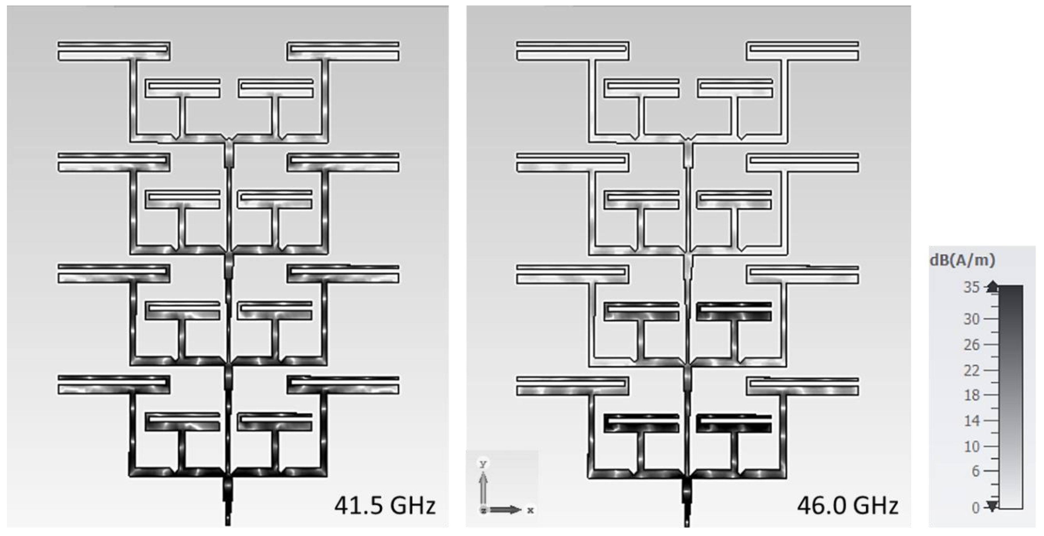
3.5. Surface Current Distribution
3.6. Effect of Notches and Cuts
3.7. Performance Comparison
4. Conclusions
Author Contributions
Funding
Institutional Review Board Statement
Informed Consent Statement
Data Availability Statement
Acknowledgments
Conflicts of Interest
References
- Mobile Phone History. Celebrating Mobile Life. Available online: http://www.mobilephonehistory.co.uk (accessed on 13 December 2021).
- GSM History. Inside the Mobile Revolution. Available online: http://www.gsmhistory.com/inside-the-mobile-revolution/ (accessed on 13 January 2022).
- Raychaudhuri, D.; Mandayam, N.B. Frontiers of Wireless and Mobile Communications. Proc. IEEE 2012, 100, 824–840. [Google Scholar] [CrossRef]
- Neog, P.; Bera, R. Multi-standard radio for 2G to 5G. In Proceedings of the 2017 2nd International Conference on Telecommunication and Networks (TEL-NET), Noida, India, 10–11 August 2017; pp. 1–5. [Google Scholar] [CrossRef]
- De Raeve, N.; Shahid, A.; de Schepper, M.; De Poorter, E.; Moerman, I.; Verhaevert, J.; Van Torre, P.; Rogier, H. Bluetooth-Low-Energy-Based Fall Detection and Warning System for Elderly People in Nursing Homes. J. Sens. 2022, 22, 9930681. [Google Scholar] [CrossRef]
- Loubet, G.; Takacs, A.; Dragomirescu, D. Implementation of a Battery-Free Wireless Sensor for Cyber-Physical Systems Dedicated to Structural Health Monitoring Applications. IEEE Access 2019, 7, 24679–24690. [Google Scholar] [CrossRef]
- Ashfaq, Z.; Mumtaz, R.; Rafay, A.; Zaidi, S.M.H.; Saleem, H.; Mumtaz, S.; Shahid, A.; De Poorter, E.; Moerman, I. Embedded AI-Based Digi-Healthcare. Appl. Sci. 2022, 12, 519. [Google Scholar] [CrossRef]
- Dai, M.; Zhan, K.; Peng, R.; Xu, J.; Luo, H.; Liu, Y.; Luo, L.; Wen, H.; Chen, S. A Novel Ultrasonic Doppler Fetal Heart Rate Detection System Using Windowed Digital Demodulation. IEEE Access 2021, 9, 79326–79342. [Google Scholar] [CrossRef]
- Moynihan, R.; Sanders, S.; Michaleff, Z.A.; Scott, A.M.; Clark, J.; To, E.J.; Jones, M.; Kitchener, E.; Fox, M.; Johansson, M.; et al. Impact of COVID-19 pandemic on utilisation of healthcare services: A systematic review. BMJ Open 2021, 11, e045343. [Google Scholar] [CrossRef]
- Hong, W.; Jiang, Z.H.; Yu, C.; Hou, D.; Wang, H.; Guo, C.; Hu, Y.; Kuai, L.; Yu, Y.; Jiang, Z.; et al. The Role of Millimeter-Wave Technologies in 5G/6G Wireless Communications. IEEE J. Microw. 2021, 1, 101–122. [Google Scholar] [CrossRef]
- Burr, A.G. The multipath problem: An overview. In Proceedings of the IEE Colloquium on Multipath Countermeasures, London, UK, 23 May 1996; pp. 1/1–1/7. [Google Scholar] [CrossRef]
- Global Mobile Suppliers Association. The Road to 5G: Drivers, Applications, Requirements and Technical Development. A GSA Executive Report from Ericsson, Huawei and Qualcomm. Available online: https://gsacom.com/paper/the-road-to-5g-drivers-applications-requirements-and-technical-development/ (accessed on 30 January 2022).
- Sharony, J. Introduction to Wireless MIMO—Theory and Applications. 15 November 2006. Available online: https://ieee.li/pdf/viewgr-aphs/introduction_to_wireless_mimo.pdf (accessed on 25 January 2022).
- Bevelacqua, P.J. Antenna Arrays: Performance Limits and Geometry Optimization. Ph.D. Thesis, Arizona State University, Tempe, Arizon, USA, May 2008. Available online: http://www.antenna-theory.com/Bevelacqua-Dissertation.pdf (accessed on 25 January 2022).
- Husbands, R.; Ahmed, Q.; Wang, J. Transmit antenna selection for massive MIMO: A knapsack problem formulation. In Proceedings of the 2017 IEEE International Conference on Communications (ICC), Paris, France, 21–25 May 2017; pp. 1–6. [Google Scholar] [CrossRef]
- Shen, X.; Liu, Y.; Zhao, L.; Huang, G.-L.; Shi, X.; Huang, Q. A Miniaturized Microstrip Antenna Array at 5G Millimeter-Wave Band. IEEE Antennas Wirel. Propag. Lett. 2019, 18, 1671–1675. [Google Scholar] [CrossRef]
- Hwang, I.-J.; Ahn, B.; Chae, S.-C.; Yu, J.-W.; Lee, W.-W. Quasi-Yagi Antenna Array with Modified Folded Dipole Driver for mmWave 5G Cellular Devices. IEEE Antennas Wirel. Propag. Lett. 2019, 18, 971–975. [Google Scholar] [CrossRef]
- Alluhaibi, O.; Ahmed, Q.Z.; Kampert, E.; Higgins, M.D.; Wang, J. Revisiting the Energy-Efficient Hybrid D-A Precoding and Combining Design for mm-Wave Systems. IEEE Trans. Green Commun. Netw. 2020, 4, 340–354. [Google Scholar] [CrossRef]
- Xu, Z.; Deng, C. High-Isolated MIMO Antenna Design Based on Pattern Diversity for 5G Mobile Terminals. IEEE Antennas Wirel. Propag. Lett. 2020, 19, 467–471. [Google Scholar] [CrossRef]
- Ta, S.X.; Choo, H.; Park, I. Broadband Printed-Dipole Antenna and Its Arrays for 5G Applications. IEEE Antennas Wirel. Propag. Lett. 2017, 16, 2183–2186. [Google Scholar] [CrossRef]
- Park, J.-S.; Ko, J.-B.; Kwon, H.-K.; Kang, B.-S.; Park, B.; Kim, D. A Tilted Combined Beam Antenna for 5G Communications Using a 28-GHz Band. IEEE Antennas Wirel. Propag. Lett. 2016, 15, 1685–1688. [Google Scholar] [CrossRef]
- Lin, Q.W.; Wong, H.; Zhang, X.Y.; Lai, H.W. Printed Meandering Probe-Fed Circularly Polarized Patch Antenna with Wide Bandwidth. IEEE Antennas Wirel. Propag. Lett. 2014, 13, 654–657. [Google Scholar] [CrossRef]
- Alluhaibi, O.; Ahmed, Q.Z.; Pan, C.; Zhu, H. Hybrid Digital-to-Analog Beamforming Approaches to Maximise the Capacity of mm-Wave Systems. In Proceedings of the 2017 IEEE 85th Vehicular Technology Conference (VTC Spring), Sydney, Australia, 4–7 June 2017; pp. 1–5. [Google Scholar] [CrossRef]
- Khalily, M.; Tafazolli, R.; Xiao, P.; Kishk, A.A. Broadband mm-Wave Microstrip Array Antenna with Improved Radiation Characteristics for Different 5G Applications. IEEE Trans. Antennas Propag. 2018, 66, 4641–4647. [Google Scholar] [CrossRef]
- Mak, K.M.; Lai, H.W.; Luk, K.M.; Chan, C.H. Circularly Polarized Patch Antenna for Future 5G Mobile Phones. IEEE Access 2014, 2, 1521–1529. [Google Scholar] [CrossRef]
- Al Abbas, E.; Ikram, M.; Mobashsher, A.T.; Abbosh, A. MIMO Antenna System for Multi-Band Millimeter-Wave 5G and Wideband 4G Mobile Communications. IEEE Access 2019, 7, 181916–181923. [Google Scholar] [CrossRef]
- Li, T.; Chen, Z.N. Wideband Substrate-Integrated Waveguide-Fed Endfire Metasurface Antenna Array. IEEE Trans. Antennas Propag. 2018, 66, 7032–7040. [Google Scholar] [CrossRef]
- Li, A.; Luk, K.-M. Millimeter-Wave Dual Linearly Polarized Endfire Antenna Fed by 180° Hybrid Coupler. IEEE Antennas Wirel. Propag. Lett. 2019, 18, 1390–1394. [Google Scholar] [CrossRef]
- Li, H.; Li, Y.; Chang, L.; Sun, W.; Qin, X.; Wang, H. A Wideband Dual-Polarized Endfire Antenna Array with Overlapped Apertures and Small Clearance for 5G Millimeter-Wave Applications. IEEE Trans. Antennas Propag. 2020, 69, 815–824. [Google Scholar] [CrossRef]
- Li, Y.; Chen, Z.N.; Qing, X.; Zhang, Z.; Xu, J.; Feng, Z. Axial Ratio Bandwidth Enhancement of 60-GHz Substrate Integrated Waveguide-Fed Circularly Polarized LTCC Antenna Array. IEEE Trans. Antennas Propag. 2012, 60, 4619–4626. [Google Scholar] [CrossRef]
- Sun, W.; Li, Y.; Chang, L.; Li, H.; Qin, X.; Wang, H. Dual-Band Dual-Polarized Microstrip Antenna Array Using Double-Layer Gridded Patches for 5G Millimeter-Wave Applications. IEEE Trans. Antennas Propag. 2021, 69, 6489–6499. [Google Scholar] [CrossRef]
- Zong, W.; Li, C.; Qu, X. Review of recent development of minature and multi-band antennas for mobile handsets. In Proceedings of the 2014 3rd Asia-Pacific Conference on Antennas and Propagation, Harbin, China, 26–29 July 2014; pp. 321–324. [Google Scholar] [CrossRef]
- Final Acts WRC-15, International Telecommunication Union. In Proceedings of the World Radio communication Conference, Geneva, Switzerland, 2–27 November 2015; Available online: https://www.itu.int/dms_pub/itur/opb/act/R-ACT-WRC.12-2015-PDF-E.pdf (accessed on 30 January 2022).
- Shoaib, S. MIMO Antennas for Mobile Handsets and Tablet Application. Ph.D. Thesis, Queen Mary University of London, London, UK, May 2016. Available online: https://qmro.qmul.ac.uk/xmlui/handle/123456789/12921 (accessed on 12 October 2020).
- Shoaib, N.; Shoaib, S.; Khattak, R.Y.; Shoaib, I.; Chen, X.; Perwaiz, A. MIMO Antennas for Smart 5G Devices. IEEE Access 2018, 6, 77014–77021. [Google Scholar] [CrossRef]
- Yang, T.Y.; Hong, W.; Zhang, Y. An SICL-Excited Wideband Circularly Polarized Cavity-Backed Patch Antenna for IEEE 802.11aj (45 GHz) Applications. IEEE Antennas Wirel. Propag. Lett. 2015, 15, 1265–1268. [Google Scholar] [CrossRef]
- Zhang, Y.; Hong, W.; Mittra, R. 45 GHz Wideband Circularly Polarized Planar Antenna Array Using Inclined Slots in Modified Short-Circuited SIW. IEEE Trans. Antennas Propag. 2019, 67, 1669–1680. [Google Scholar] [CrossRef]
- Yu, S.; Hong, W.; Zhang, Y.; Jiang, M. Packaged Ultra Broadband Terminal Antenna for 45GHz Band IEEE 802.11aj Applications. IEEE Trans. Antennas Propag. 2016, 64, 5153–5162. [Google Scholar] [CrossRef]
- Ahmed, I.; Shoaib, S.; Shah, R.A. Quad Sector HMSIW Tapered Slot Antenna Array for Millimeter-Wave Applications. Electronics 2021, 10, 1645. [Google Scholar] [CrossRef]


| S. No. | Antenna Dimensions | |||||
|---|---|---|---|---|---|---|
| Parameter | Value | Parameter | Value | Parameter | Value | |
| 1 | 10.00 | 18.00 | 7.65 | |||
| 2 | 6.00 | 12.00 | 6.70 | |||
| 3 | 6.00 | 2.00 | 9.0 | |||
| 4 | 3.00 | 3.65 | 1.40 | |||
| 5 | 0.50 | 0.35 | 0.69 | |||
| 6 | 0.70 | 0.70 | 0.30 | |||
| 7 | 0.20 | 1.50 | 90° | |||
| 8 | 0.40 | 36.00 | 9.50 | |||
| 9 | 0.30 | 15.00 | 4.73 | |||
| 10 | 0.30 | |||||
| Design Step | Comparison Parameter | ||
|---|---|---|---|
| Average Efficiency | Average Gain | 6 dB Bandwidth | |
| 1 | 77.0% | 5.52 | 2.5 GHz |
| 3 | 80.0% | 7.98 | 4.0 GHz |
| 5 | 84.1% | 11.52 | 7.8 GHz |
| Freq. (GHz) | Antenna Gain (dB) | Efficiency (%) | |
|---|---|---|---|
| Simulated | Measured | Simulated | |
| 40.5 | 8.66 | 7.50 | 70 |
| 41.5 | 10.14 | 8.60 | 91 |
| 43.9 | 12.61 | 10.5 | 79 |
| 45.9 | 12.25 | 10.6 | 92 |
| 47.0 | 13.72 | 11.2 | 93 |
| 48.3 | 11.78 | 11.6 | 76 |
| Citation | Shape/Type | Size | Fractional Bandwidth | Average Gain |
|---|---|---|---|---|
| [16] | Multilayer Printed Microstrip | 15 × 13 | 0.18 | 7.00 dB |
| [29] | Multilayer SIW-Based Microstrip | 33 × 18 | 0.20 | 9.00 dB |
| [35] | Printed 8-Element MIMO | 31 × 31 | 0.15 | 6.40 dB |
| [36] | SICL-Excited SIW Patch Antenna | 30 × 60 | 0.18 | 8.60 dB |
| [37] | CP Antenna Array | 30 × 30 | 0.14 | 8.00 dB |
| [38] | Dual-Dipole SIW | 10 × 40 | 0.32 | 3.00 dB |
| [39] | Tapered Slot, SIW | 20 × 70 | 0.07 | 12.0 dB |
| Proposed | Printed Microstrip Array | 28 × 40 | 0.18 | 11.5 dB |
Publisher’s Note: MDPI stays neutral with regard to jurisdictional claims in published maps and institutional affiliations. |
© 2022 by the authors. Licensee MDPI, Basel, Switzerland. This article is an open access article distributed under the terms and conditions of the Creative Commons Attribution (CC BY) license (https://creativecommons.org/licenses/by/4.0/).
Share and Cite
Khattak, R.Y.; Ahmed, Q.; Shoaib, S.; Hafeez, M. Array Antenna for Wireless Access Points and Futuristic Healthcare Devices. Electronics 2022, 11, 1226. https://doi.org/10.3390/electronics11081226
Khattak RY, Ahmed Q, Shoaib S, Hafeez M. Array Antenna for Wireless Access Points and Futuristic Healthcare Devices. Electronics. 2022; 11(8):1226. https://doi.org/10.3390/electronics11081226
Chicago/Turabian StyleKhattak, Riqza Yasmin, Qasim Ahmed, Sultan Shoaib, and Maryam Hafeez. 2022. "Array Antenna for Wireless Access Points and Futuristic Healthcare Devices" Electronics 11, no. 8: 1226. https://doi.org/10.3390/electronics11081226
APA StyleKhattak, R. Y., Ahmed, Q., Shoaib, S., & Hafeez, M. (2022). Array Antenna for Wireless Access Points and Futuristic Healthcare Devices. Electronics, 11(8), 1226. https://doi.org/10.3390/electronics11081226