Article

Efficient Low-Complexity Turbo-Hadamard Code in UAV Anti-Jamming Communications

1
School of Information and Electronics, Beijing Institute of Technology, Beijing 100081, China
2
Science and Technology on Electronic Information Control Laboratory, Chengdu 610043, China
3
School of Cyberspace Science and Technology, Beijing Institute of Technology, Beijing 100081, China
*
Author to whom correspondence should be addressed.
Electronics 2022, 11(7), 1088; https://doi.org/10.3390/electronics11071088
Submission received: 23 January 2022 / Revised: 19 March 2022 / Accepted: 22 March 2022 / Published: 30 March 2022
(This article belongs to the Special Issue Unmanned Aerial Vehicle (UAV) Communication and Networking)

Abstract

:
Unmanned aerial vehicle (UAV) systems undergo a period of rapid development in both civil and military scenarios. A major challenge in the malicious jamming environment is to guarantee the reliability of UAV communications links. Frequency hopping (FH) is one of the most commonly used means of combatting the influence brought about by jamming. In this paper, we integrate low-rate codes into an anti-jamming FH communications system, and propose an efficient and low-complexity turbo-Hadamard code scheme. Tail-biting is applied to design the component convolutional-Hadamard codes, and a corresponding decode algorithm is used for implementation in the UAV hardware platform. Numerical simulation results demonstrate that the anti-jamming performance of this method is improved as compared with conventional concatenated codes. Finally, we compare the complexity and transmission efficiency of the proposed algorithm with the algorithms implemented on the field programmable gate array (FPGA) platform in detail.

1. Introduction

Unmanned aerial vehicles (UAVs) have been applied extensively in a wide range of scenarios during the past decade [1,2,3,4,5,6], as they represent a promising avenue of research, providing flexible deployment and on-demand mobility in a cost-effective way. In particular, UAVs are playing increasingly crucial roles in applications in which human lives would otherwise be endangered. As for military applications, UAVs become indispensable in reconnaissance [1], surveillance [2] and strikes [3]; meanwhile, UAVs are essential in disaster relief [4], remote sensing [5] and weather forecasting [6] in civil scenarios. The performance of UAVs depends heavily on the quality of wireless communication links between UAVs.
However, UAVs’ wireless communication links are vulnerable to jamming due to their exposed nature [7]. As a result, anti-jamming performance has become an important design metric for the wireless communication systems of UAVs. However, most existing research contributions on UAVs have focused on the analysis and improvement of their links and quality of servicein conditions without jamming [8,9,10,11]. The quality of those wireless links can be particularly worsened in the complex electromagnetic environment of the battlefield. Hence, anti-jamming in UAV communications has attracted substantial research interest. At present, the frequency hopping (FH) spread spectrum technique works well in combating jamming. The FH system gains its anti-jamming performance through frequency domain diversity. The frequency bin selection mechanism of the FH communication system is pseudo-randomly varied, which produces outstanding anti-jamming performance [12]. With the development of different methods of jamming, the application of the FH scheme alone can not guarantee the quality of UAV communications links in the face of malicious jamming. Therefore, it is worthwhile to consider the use of advanced waveform design methods, such as interleaving, channel coding and efficient modulation techniques [13]. The channel coding scheme has been demonstrated to be essential in FH systems due to the high coding gain it has demonstrated.
Substantial research has been conducted with the aim of applying various coding algorithm to FH communication systems in diverse UAV scenarios. Reed–Solomon (RS) codes, convolutional codes, turbo codes and low-density parity check (LDPC) codes are widely studied in FH systems [13,14,15,16,17]. Those codes demonstrate a considerable coding gain against noise. However, since the code rates of those codes are not low enough, they cannot be used to combat malicious jamming with high power, which can cause the received symbols to be entirely suppressed by powerful interference, meaning that the receiver cannot succeed in decoding the message at all.As a result, it has become critical to combine low-rate codes with FH communication systems in UAVs for the purpose of anti-jamming.
Hadamard codes are one kind of low-rate code, which can be decoded with a rather low complexity, employing prior information by means of maximum posterior (MAP) decoding rules [18]. Meanwhile, turbo codes have been proven to achieve coding gains close to the Shannon limit [19], and have been demonstrated to combat jamming effectively due to the characteristics of their interleaving-coded bit sequence. As a consequence, a hybrid concatenation of convolutional codes and Hadamard codes called the turbo-Hadamard code was proposed in [20], featuring a low rate and anti-jamming capability. This proposed code can be treated as an approximately random code which is proven to be a “good code” when the code length becomes ∞. Low-rate codes have been employed when the complexity is acceptable in 6G UAV scenarios [21]. However, the high complexity of the decoding of turbo-Hadamard codes is one obstacle to its implementation on the platform of limited UAVs. Moreover, turbo-Hadamard codes exhibit great efficiency losses due to their trellis structure with short information bits. Therefore, it is critical to solve the problems of high decoding complexity and high efficiency losses for the platform of resource-limited UAVs.
In this paper, we focus on applying the turbo-Hadamard codes to an FH system for anti-jamming purposes. We employ approximate algorithms to greatly reduce the decoding complexity [22], which results in the effect that the usages of lookup tables (LUTs) are reduced by more than 20 % compared to the practical low-rate codes [23,24]. Considering the fact that the information package is usually short in UAVs [25], we proposed the use of advanced tail-biting turbo-Hadamard codes, which are constructed by concatenating several tail-biting convolutional-Hadamard codes in parallel in order to reduce the communication latency [26]. Simulation results showed that the proposed tail-biting turbo-Hadamard codes performed better than other low-rate codes when faced with various jamming conditions.
The contributions of this paper are as follows:
1.
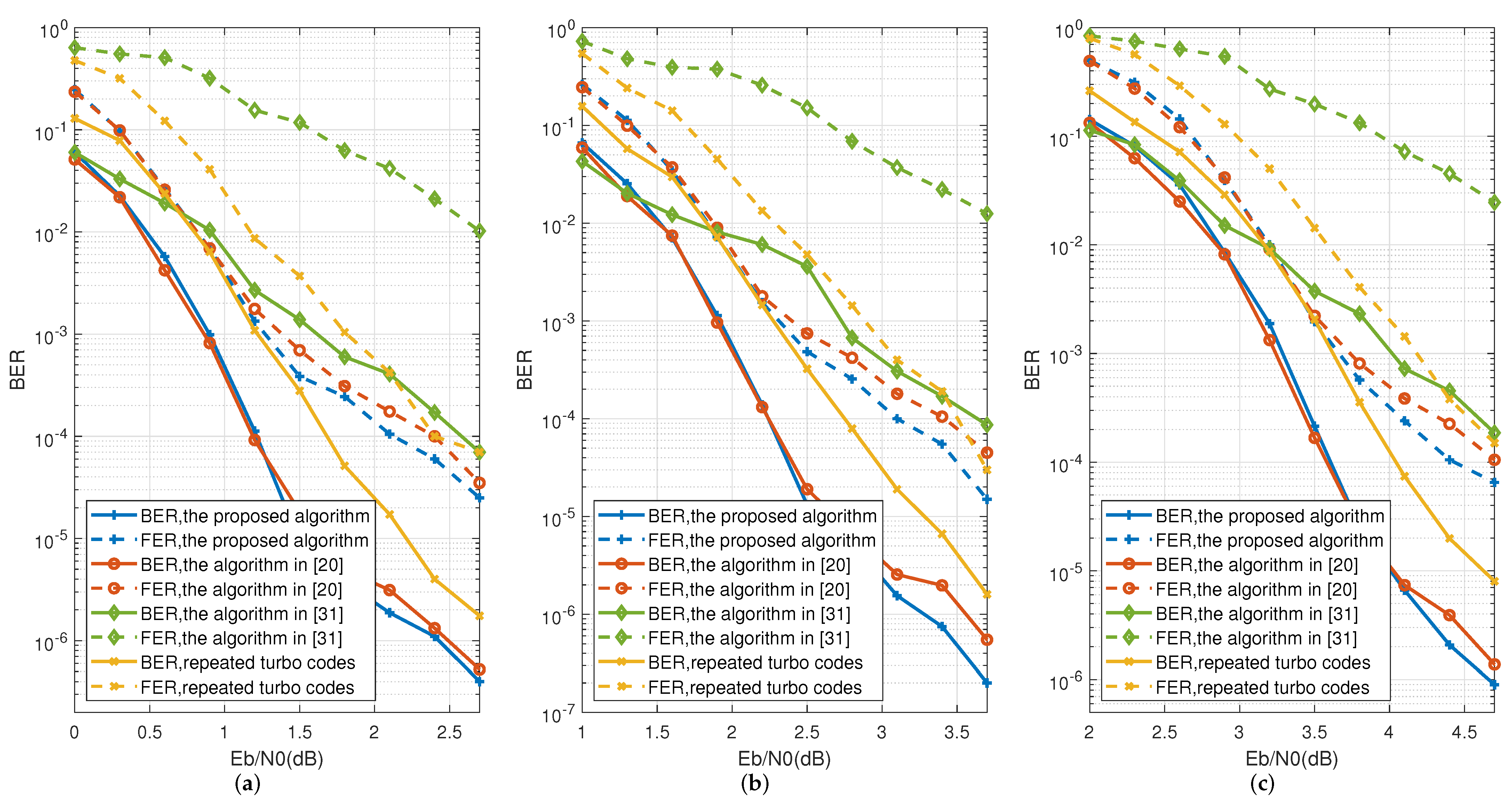
An improved turbo-Hadamard code based on tail-biting is proposed. The proposed codes outperform the conventional terminate-state-zeroturbo-Hadamard codes in terms of the coding gain and anti-jamming performance. Since we introduced no redundant bits, our algorithm has proven to be more efficient than other low-rate codes, especially in the UAV communication scenarios requiring extremely short code lengths.
2.
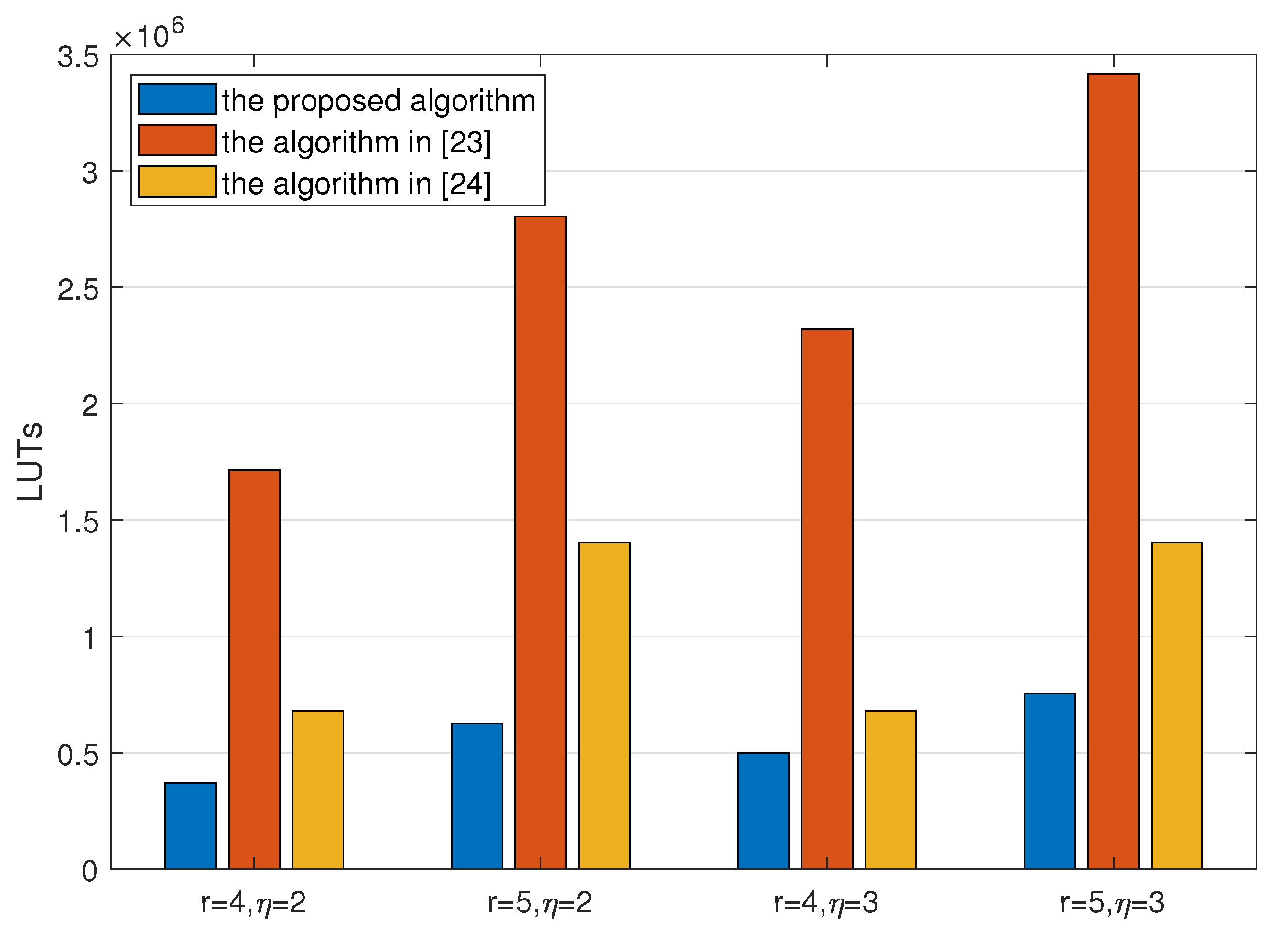
A corresponding decoding scheme is proposed. For easy implementation on the hardware platforms of resource-limited UAVs, we employ addition operations instead of multiplication, division, exponential and logarithm operations. We prove that the proposed algorithm consumes fewer resources than the existing concatenated low-rate codes FPGA platform.
3.
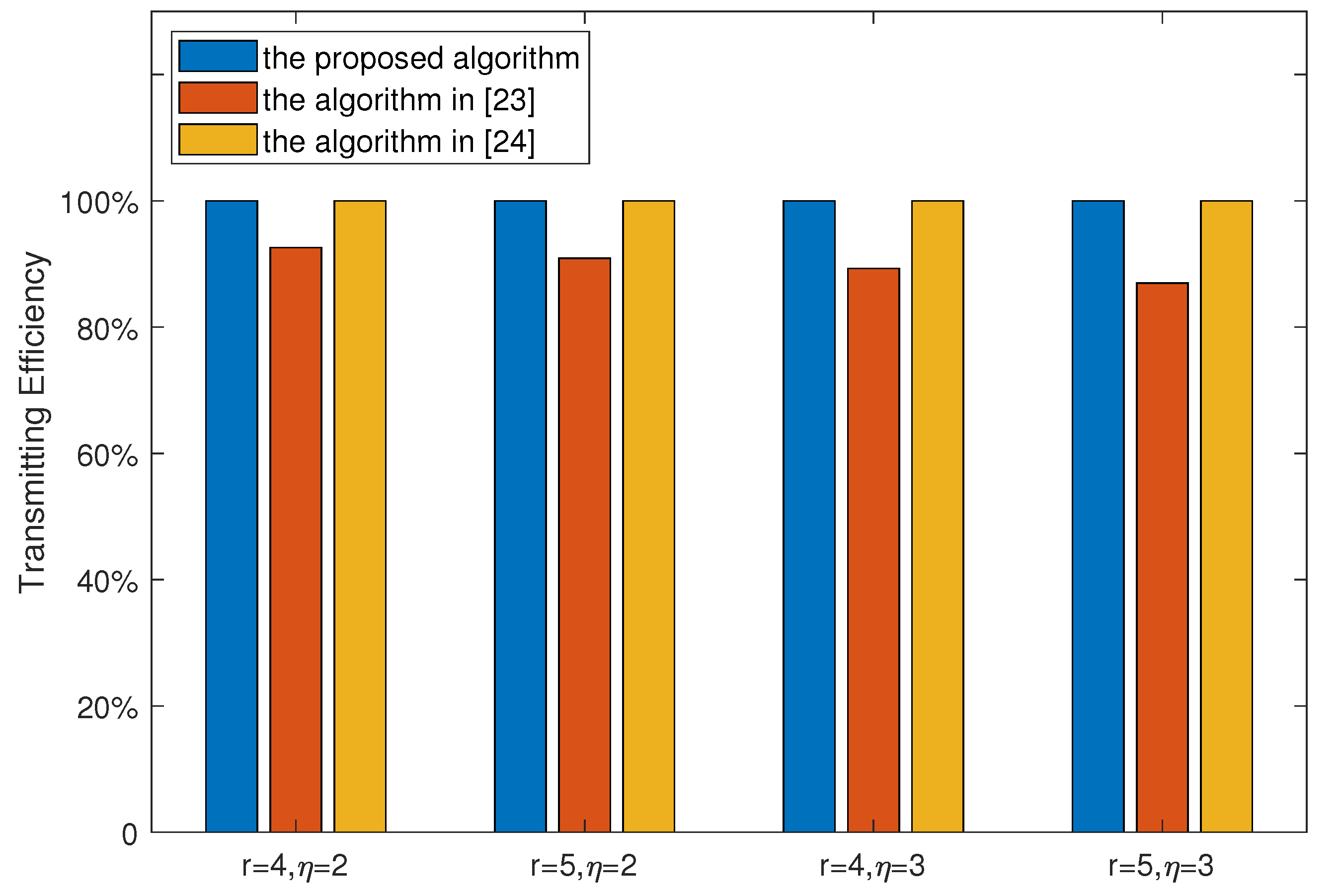
The expression of the computational complexity and transmission efficiency are given in closed form. Meanwhile, we analyze the complexity and efficiency of the proposed tail-biting turbo-Hadamard codes in detail.
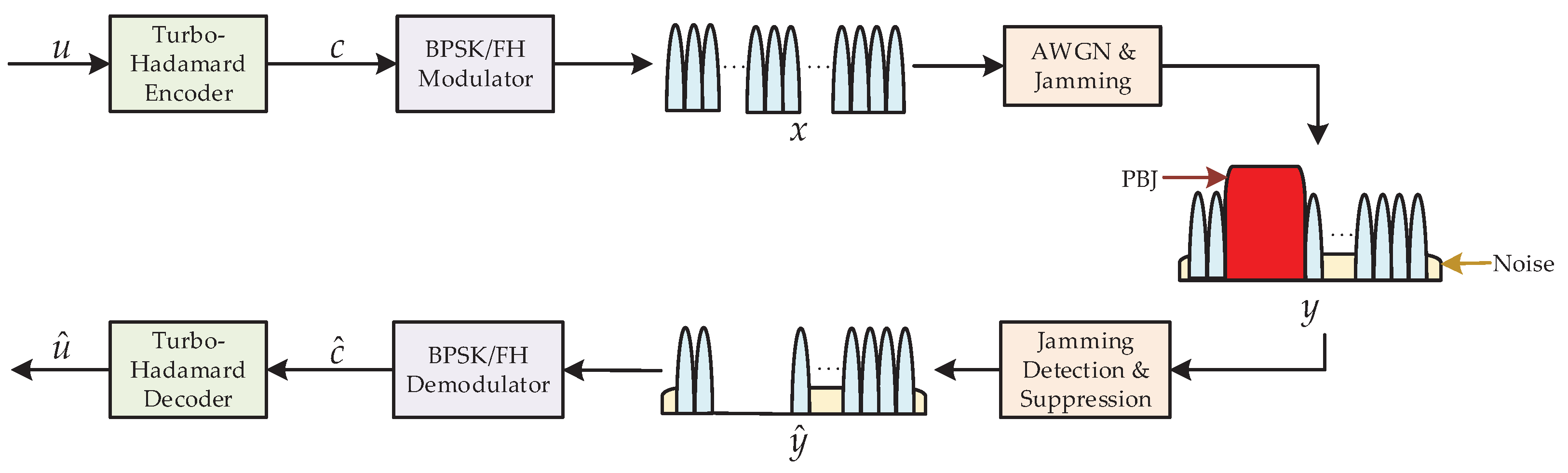
The structure of this paper is organized as follows: Section 2 presents a description of the system model. Section 3 introduces the encoder and decoder of turbo-Hadamard codes based on tail-biting. Section 4 presents the simulation results and an analysis of tail-biting turbo-Hadamard codes. Section 5 summarizes the contributions of this paper.

2. System Model

As shown in Figure 1, we consider an FH communication system having one single-antenna transmitter and one single-antenna receiver, but in which the system performance is degraded by jamming methods, such as single-tone jamming, multiple tone jamming, and partial band jamming, etc.
At the transmission side, extra parity bits are added via an encoder to improve the reliability of the communication system. In light of the high performance and low complexity, we adopt turbo-Hadamard as the encoding scheme. Therefore, the N encoded bits c = ( c 1 , c 2 , , c N ) can be represented as
c = TH u ,
where TH ( · ) represents the turbo-Hadamard encoder function, which will be discussed in detail in Section 3, and u = ( u 1 , u 2 , , u W ) denotes W uncoded bits to be transmitted. For simplicity but without the loss of generality, suppose that binary phase shift keying (BPSK) is adopted. It is worth noting that other modulation schemes are also suitable in this scenario. The transmitted symbols are then modulated by G frequency bins according to the frequency hopping pattern. To combat complex electromagnetic jamming in the UAV communication system, the number of frequency bins can be as large as hundreds or thousands. The transmitted signal x n , n = 1 , , N , is thus given by
x n = c n e 2 π f n + θ n ,
where f n and θ n denote the frequency and phase, respectively, for the nth encoded bit.
Considering the effect caused by jamming, we assume that ϕ   ( 0 ϕ Φ ) frequency bins are influenced by suppressive jamming in this paper. The jammed frequency bins can be represented as a set H = { f ^ j , j = 1 , 2 , , ϕ } , where f ^ j denotes the jth jammed frequency bin. Consequently, the received signal y n , n = 1 , , N , can be written as
y n =   x n + ω + i , f n H , x n + ω , f n H ,
where ω denotes the additive Gaussian white noise (AWGN) with a power spectral density of ω 0 , and i represents the suppressive jamming, with a power spectral density of i 0 . Usually, the strength of the implemented jamming strength is much larger than that of the UAV communication signal and noise. As a result, we assume that the received signals are superimposed on additional noise with high power once the frequency bin is jammed, whereas the signals on the other frequency bins are treated as normal.
Since there is an obvious strength gap between signals with and without jamming, the receiver can easily find out which frequency bins are jammed based on the received power. Therefore, the receiver can set the power of signal on the jammed frequency bins to zero by employing notch filter on account of the detection of the whole spectrum. As it is not possible to know which frequency bins are jammed before communication, the transmitted encoded bits are interleaved as randomly as possible before modulation in order to lower the impact of jamming. Each bit is modulated onto every frequency bin in the same probability due to the above interleaving operation. Therefore, the probability of received signals in the jammed frequency bins is ϕ / Φ , whereas the probability of normal received signals is 1 ϕ / Φ . Hence, the received signal y ^ n , n = 1 , , N , can be represented as
y ^ n =   0 , probability ϕ / Φ , x n + ω , probability 1 ϕ / Φ .
Admittedly, the performance of the BPSK/FH demodulator depends heavily on both a reliable capture progress and a precise synchronization progress. Since our emphasis in this paper is on improving the FH code scheme, the received signal is assumed to be demodulated and synchronized perfectly. As a consequence, the sequence to be decoded c ^ n , n = 1 , , N can be represented equivalently as
c ^ n =   0 , probability ϕ / Φ , c n + ω ^ , probability 1 ϕ / Φ ,
where c n denotes the ideal demodulated result, and ω ^ is the equivalent AWGN of which the power spectral density is ω 0 due to the application of the optimum receiver. Finally, the receiver in the UAV communication system can obtain the decoded bits u ^ after the turbo-Hadamard decoder progress.

3. Low-Complexity Turbo-Hadamard Codes Based on Tail-Biting

The turbo-Hadamard code is a kind of hybrid concatenation code, which consist of convolutional codes and Hadamard codes [20]. As illustrated in [27,28], the turbo-Hadamard code performs well in the case of narrow-band interference suppression since it can achieve relatively high code gains at great lengths due to its low-rate structure.However, in the scenario of UAV communications, the payload is usually low, and the turbo-Hadamard code will thus exhibit high efficiency losses, especially at a relatively short code length. As a result, we propose an improved turbo-Hadamard code based on tail-biting in the convolutional process, in order to make it more available for UAV communication systems. In this section, we will discuss the structure of the component codes firstly, and then discuss the overall codes.

3.1. The Tail-Biting Convolutional-Hadamard Encoder

To avoid the rate loss caused by zero-tail termination in the convolutional coding part of the scheme, a modified convolutional-Hadamard encoder based on tail-biting is proposed to improve the coding rate, which is described in Algorithm 1 in detail.
Algorithm 1 Tail-Biting Convolutional-Hadamard Encoder Algorithm.
Input: Block information bit { d k } of size K × r . Tail-biting convolutional generator g ( x ) .
Output: Tail-biting convolutional-Hadamard code C .
  1:
Initialize the state of convolutional encoder into all zeros.
  2:
Get the parity check bit of d k as q k .
  3:
Calculate the cyclic state s c based on g ( x ) and q = { q k } .
  4:
Encode q using the convolutional code generated by g ( x ) with the cyclic state s c , and get the parity check bit stream q .
  5:
Encode the { d k , q k } using an order-r Hadamard code as c k = { d k , q k , p k } .
  6:
Arrange c k as the the kth row of C .
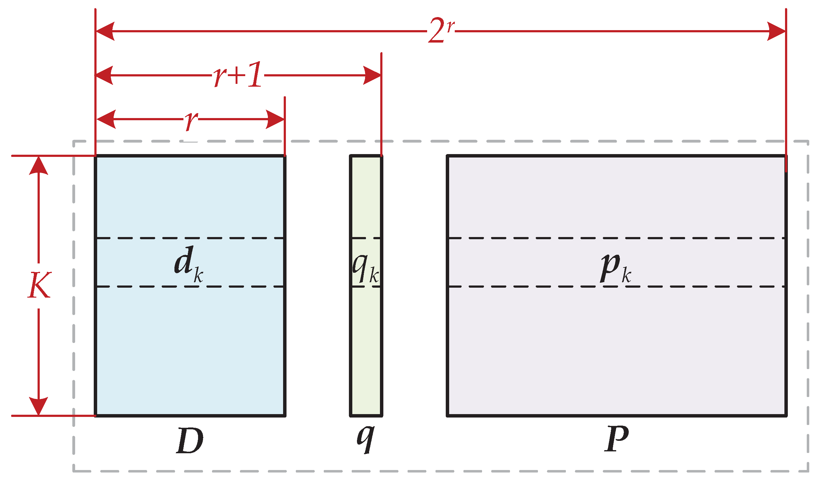
  • Input: For ease of description, the length-W uncoded bits u are segmented into { d k } , k = 1 , 2 , , K . Each row d k consists of r bits, where r is the order of Hadamard codes. It is worth noting that W = K × r .
  • Line 3: Cyclic state s c is the key to keeping the convolutional trellis start state s i and end state s t once the input is q . s c is calculated by g ( x ) with the initial state being all zeros. The details of how to generate s c are as follows, and as illustrated in Figure 2.
    The feedback coefficients of convolutional generator g ( x ) can be represented as the state recursive matrix G . Moreover, if the generator is described in the mode of a fraction, the denominator of g ( x ) is denoted as G . For example, the state recursive matrix of g ( x ) = 1 / 1 + x + x 2 can be given by
    G =   1 1 1 0 .
    It is essential to guarantee that the matrix I + G K 1 is nonsingular, where I denotes the order- ( η + 1 ) identity matrix, η denotes the memory depth of convolutional generator g ( x ) and ( · ) 1 denotes the inverse operator. Thus, we can obtain the final state s 0 K after K-step precoding with q from the state-0. The cyclic state s c is calculated by
    s c = I + G K 1 s 0 K .
    Since the precoder calculates the cyclic state of the convolutional code, the initial state and the terminal state of the convolutional code trellis are same. The states are explained as follows,
    s i = s t = s c { s 0 , , s 2 η 1 } .
  • Line 5: Encode length- ( r + 1 ) using order-r Hadamard code, which outputs the length- 2 r bitstream c k .
As shown in Figure 3, the component codewords C can be expressed as C = { D , q , P } , where D denotes the K × r matrix with rows being d k , and P denotes the K × ( 2 r r 1 ) matrix with rows being p k .
Compared with the algorithm [20] in which the trellis state terminates at all zeros, there are no extra redundant bits in our improved algorithm. As a consequence, the code rate of the proposed tail-biting convolution-Hadamard code is
R TB c = r 2 r ,
whereas that of the convolution-Hadamard code scheme with the terminating state at zero is
R T 0 c = K r K + η 2 r .

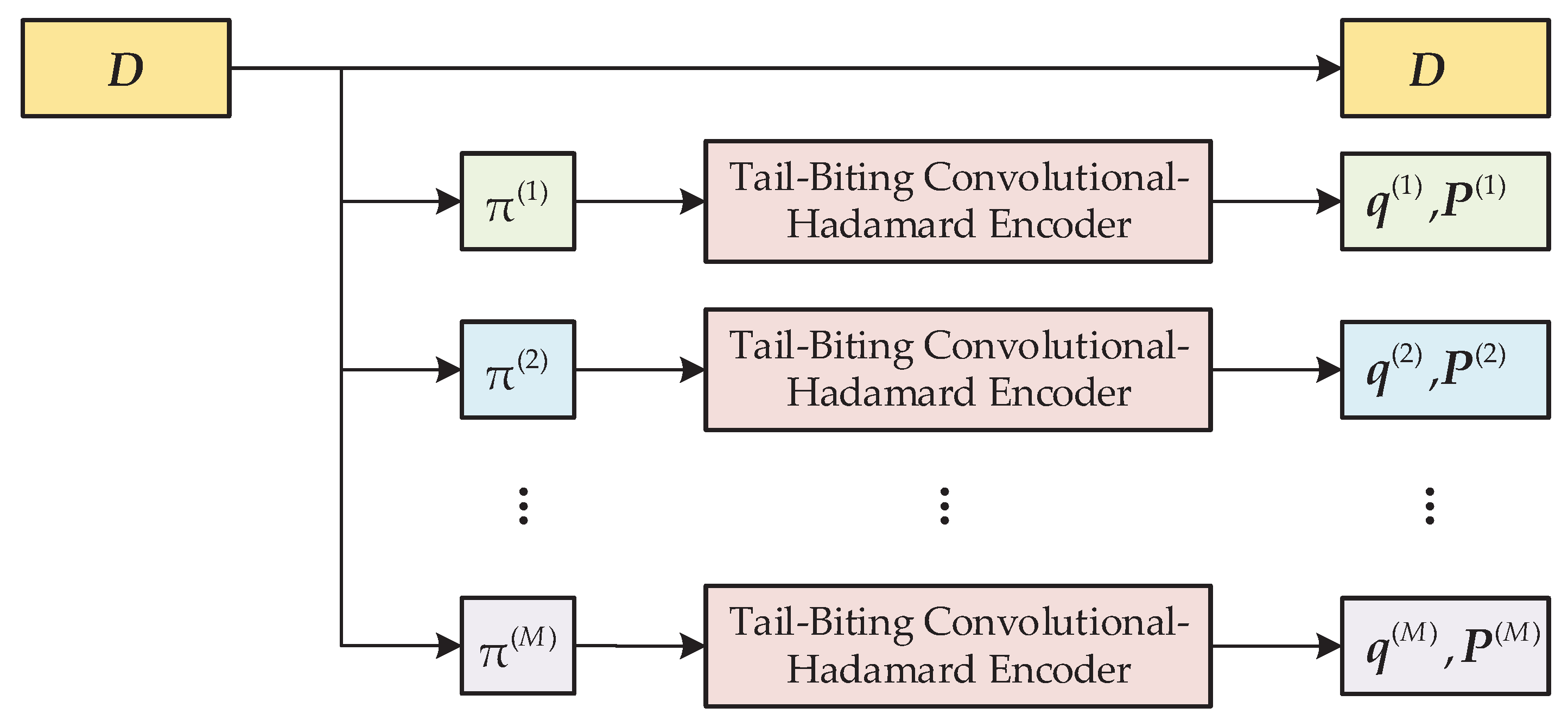
3.2. The Tail-Biting Turbo-Hadamard Encoder

As mentioned above, the component codes are constructed. To achieve higher code gains and better performance when combating jamming, the overall tail-biting turbo-Hadamard codes are made up of M component convolutional-Hadamard codes. As for each component code, the output bits of different interleavers are entered into the same tail-biting convolutional-Hadamard encoder; thus, the mth component tail-biting convolutional codewords can be given by C ( m ) = { D ( m ) , q ( m ) , P ( m ) } , m = 1 , 2 , , M . Moreover, the transmitter only sends the { q ( m ) , P ( m ) } part of each component code to avoid reducing the transmission efficiency. Meanwhile, considering the complexity of the decoder, the value of M should not be too large. The overall codewords C of the tail-biting turbo-Hadamard can be written in
C = { D , q ( 1 ) , P ( 1 ) , q ( 2 ) , P ( 2 ) , , q ( M ) , P M } .
As shown in Figure 4, the uncoded bits are interleaved via each interleaver π ( m ) , m = 1 , 2 , , M . It is worth noting that the performance of the improved tail-biting turbo-Hadamard codes are related to the correlation of each interleaver.
The code rate of the tail-biting turbo-Hadamard code is
R TB = r r + M 2 r r ,
whereas that of the terminate-state-zeroturbo-Hadamard code is given by
R T 0 = r 1 + η / K r + M 2 r r .
The efficiency loss in the terminate-state-zero turbo-Hadamard scheme is η / K . When the information stream is very short, for instance, 100 bits, the efficiency loss is 10% ( r = 5 , η = 2 ). However, the tail-biting turbo-Hadamard code does not exhibit this efficiency loss at all.

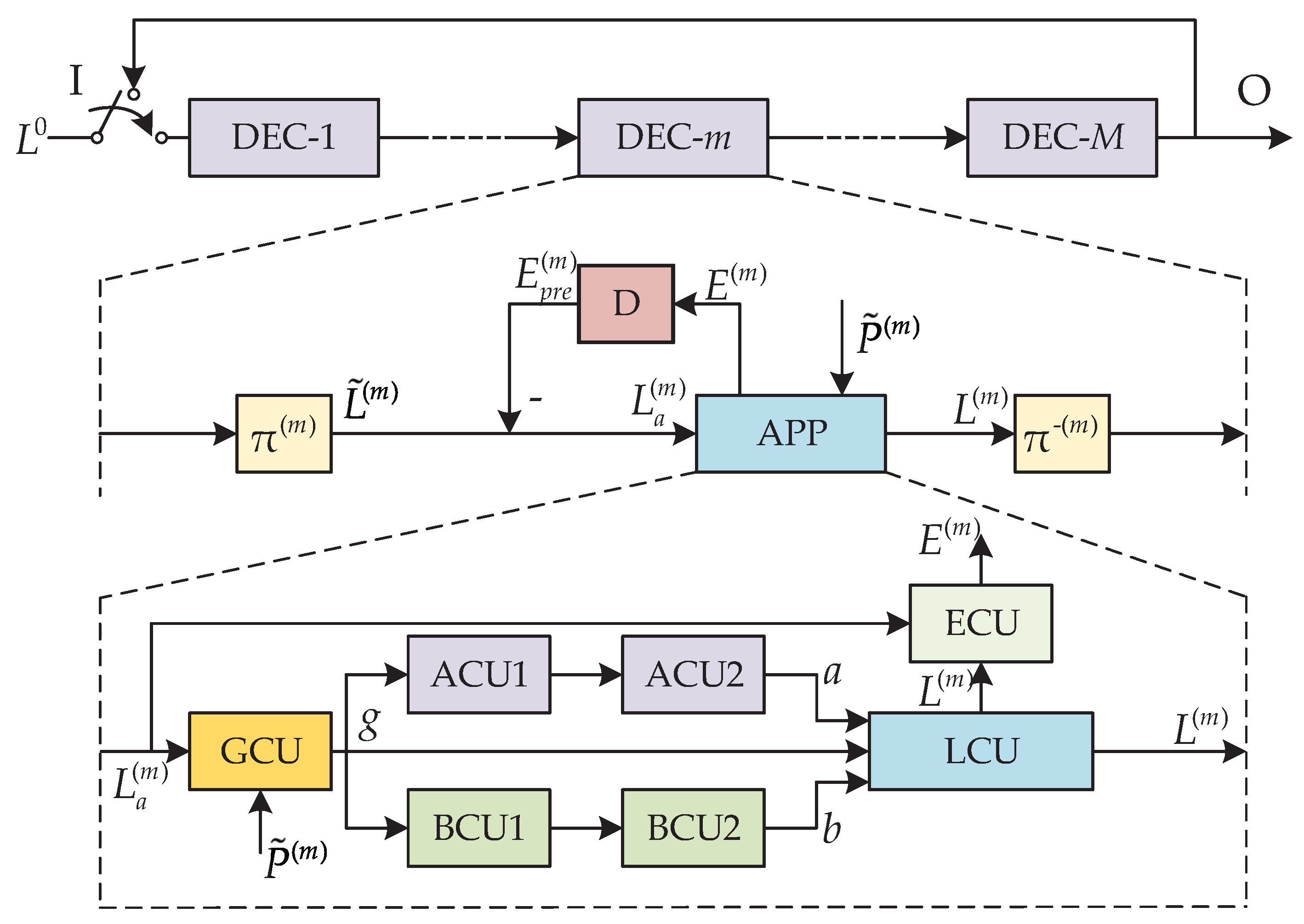
3.3. The Tail-Biting Turbo-Hadamard Decoder

The tail-biting turbo-Hadamard code is kind of multiple turbo-code which can be APP-decoded by means of the Bahl, Cocke, Jelinek and Raviv (BCJR) algorithm [29]. The decoder structure is shown in Figure 5. The M component tail-biting convolutional-Hadamard decoder is involved in dealing with each component code. The log likelihood ratio (LLR) of every information bit is calculated and exchanged from one component decoder to another during decoding. The LLR of parity bits will not be calculated or exchanged.
The received symbols c ^ can be rearranged as a symbol block C ^ , which can be written by
C ^ = { D r , P r ( 1 ) , , P r ( M ) } ,
where D r denotes the information bit block of the received symbols, and P r ( m ) , m = 1 , , M denotes the m th component parity bit block (note that P r ( m ) corresponds to { q ( m ) , P ( m ) } ).
In the beginning of the iteration, the initial prior LLR of information bits L 0 = D r is entered into DEC-1. As the iteration progresses, in the m th APP decoder, the non-self prior LLR of information bits L a ( m ) is calculated by
L a ( m ) = L ˜ ( m ) E p r e ( m ) ,
where L ˜ ( m ) denotes the prior LLR of information bits fed into the DEC-m, and E p r e ( m ) denotes the extrinsic LLR of information bits in previous iteration (initialized by zeros).
The APP decoder processes the non-self prior LLR of information bits L a ( m ) and the prior LLR of parity bits P ˜ ( m ) = P r ( m ) into the posterior LLR of information bits L ( m ) based on the BCJR algorithm (See details in Algorithm 2).
Algorithm 2 Tail-Biting Convolutional-Hadamard APP Decoder Algorithm.
Input: Block extrinsic prior LLR of information bits L a of size K × r , and block prior LLR of parity bits P ˜ of size K × 2 r r .
Output: Block extrinsic LLR of information bits E of size K × r , and block posterior LLR of information bits L of size K × r .
  1:
Initialize k 1 = 1 , k 2 = 1 , k 3 = 1 = , k 4 = 1 , a 0 = 0 , b K = 0 .
  2:
repeat
  3:
    Calculate g k 1 with L a k 1 and P ˜ k 1 according to (17) in GCU.
  4:
     k 1 = k 1 + 1 .
  5:
until  k 1 = K .
  6:
repeat
  7:
    Calculate a k 2 with g k 2 and a k 2 1 according to (21) in ACU1.
  8:
    Calculate b K k 2 with g K k 2 + 1 and b K k 2 + 1 according to (23) in BCU1.
  9:
     k 2 = k 2 + 1 .
  10:
until  k 2 = K
  11:
a 0 = a K , b K = b 0 according to [30].
  12:
repeat
  13:
    Calculate a k 3 with g k 3 and a k 3 1 according to (21) in ACU2.
  14:
    Calculate b K k 3 with g K k 3 + 1 and b K k 3 + 1 according to (23) in BCU2.
  15:
     k 3 = k 3 + 1 .
  16:
until  k 3 = K
  17:
repeat
  18:
    Calculate L k 4 with g k 4 , a k 4 and b k 4 + 1 according to (25) in LCU.
  19:
    Calculate E k 4 with L k 4 and L a k 4 according to (15) in ECU.
  20:
     k 4 = k 4 + 1 .
  21:
until  k 4 = K
The extrinsic LLR of information bits E ( m ) is calculated in an extrinsic LLR computing unit (ECU) by
E ( m ) = L ( m ) L a ( m ) .
The partial branch metric γ is defined as
γ k ± h j   = A exp 1 2 ± h j , { L a k , P ˜ k } ,
where h j is the j th column of the Hadamard matrix, A is a constant, L a k is the k th row of L a , and P ˜ k is denoted as the k th row of P ˜ .
The logarithm partial branch metric g is calculated in the g computing unit (GCU) and defined as
g k ( ± h j ) = log ( γ k ( ± h j ) ) = log A + 1 2 ± h j , { L a k , P ˜ k } ,
where log A can be omitted as a constant.
The full branch metric λ is defined as
λ s k 1 , s k   = s k 1 , s k γ k ( ± h j ) ,
where λ s k 1 , s k denotes all parallel branches between s k 1 and s k . The logarithm’sfully branch metric l is defined as
l s k 1 , s k = log s k 1 , s k exp ( g k ( ± h j ) ) max s k 1 , s k ( g k ( ± h j ) ) .
The forward recursive metric α in forward recursion is defined as
α s k   = s k 1 λ s k 1 , s k α s k 1 .
The logarithm’s forward recursive metric a is calculated in the a computing unit (ACU) and defined as
a s k = log s k 1 , s k exp l s k 1 , s k + a s k 1 max s k 1 l s k 1 , s k + a s k 1 .
Correspondingly, the backward recursive metric b is defined as
β s k   = s k + 1 λ s k , s k + 1 β s k + 1 ,
and the logarithm’s backward recursive metric b is calculated in b computing units (BCU) and defined as
b s k   max s k + 1 l s k , s k + 1 + b s k + 1 .
The k th row’s i th bit of the posterior LLR of information bits L k [ i ] is calculated in the LLR computing unit (LCU) and defined as
L k [ i ] = log H [ i , j ] = ± 1 γ k ± h j s k , s k + 1 α s k β s k + 1 H [ i , j ] = 1 γ k ± h j s k , s k + 1 α s k β s k + 1 ,
and this can then be simplified to
L k [ i ] max H [ i , j ] = ± 1 g k ± h j + max s k , s k + 1 a s k + b s k + 1 max H [ i , j ] = 1 g k ± h j + max s k , s k + 1 a s k + b s k + 1 .
r denotes the order of the Hadamard code, k = K × r denotes the length of information bits and η represents the memory depth of the convolutional code. The maximum value of δ elements can be obtained by calculating the δ maximum value of ( δ 1 ) pairs’ elements. Moreover, the maximum value of an element pair can be evaluated by a subtraction and all subtraction can be evaluated by addition. Thus, calculating the maximum value of δ elements requires ( δ 1 ) additions. In each iteration, the proposed turbo-Hadamard codes based on tail-biting need to calculate K times, whereas the turbo-Hadamard codes [20] need to calculate ( K + η ) times. Therefore, we can obtain the computation complexity estimation of the decoder through (17) to (25). The computational complexity of each iteration is shown in Table 1.
We use LUTs to execute addition and multiplication operations (we treat division as multiplication) and use read-only memory (ROM) to execute exponent and logarithm operations. In the operating environment of Xilinx Vivado 2019.1, a 10-bit input takes up the resources of 10 LUTs, a 10-bit input multiplication takes up 116 LUTs, and a 10-bit exponent or logarithm takes up 0.5 Block RAMs (BRAMs). As a result, we can obtain the comparison of hardware resources occupied in our proposed algorithm and the conventional algorithm in Table 2.

4. Simulation Results

In this section, simulation results are provided to illustrate the bit error rate (BER) and frame error rate (FER) performance of the proposed tail-biting turbo-Hadamard codes, the turbo-Hadamard codes reported in [20] and the concatenated zigzag Hadamard codes reported in [31]. Meanwhile, the performance of our proposed algorithm is analyzed with and without jamming. Since the concatenated codes were implemented on the FPGA platform in [23,24], the computational complexity comparison of our proposed algorithm and codes [23,24] is illustrated from the perspective of implementation. Particularly, the trellis terminal state of turbo-Hadamard codes return to zeros; however, the trellis terminal state of our proposed algorithm is based on a cyclic state. Supposing that the capture process and synchronization process are perfect, we simulate a digital baseband FH system. The common FH system parameters are shown in the following Table 3.
In Figure 6, we show the BER performance of the proposed tail-biting turbo-Hadamard codes and terminate-state-zeroturbo-Hadamard codes in [20] considering different numbers of component coders. We set the length of uncoded bits k = 200 , the order of Hadamard matrix r = 5 , the memory depth of convolutional code η = 2 and the number of component encoders M = 2 or M = 3 . We observed that tail-biting turbo-Hadamard codes outperformed terminate state-zero turbo-Hadamard codes regardless of whether M equaled 2 or 3. This is because for each component coder, the starting state and terminating state were the same. However, only the terminating of the first component coder is a state of zero and the other is unknown in the terminate-state-zero turbo-Hadamard codes [20].The terminating state of every component coder in our proposed algorithm is determinant. This means that our proposed algorithm has more prior status information than the codes presented in [20]. Furthermore, our algorithm’s performance with regard to M = 3 exceeded that regarding M = 2 in every turbo-Hadamard code.The reason for this is that the codes with three component codes have more constraints on the information bits than those with only two component codes.
The impact of the order of Hadamard codes on the BER performance of turbo-Hadamard codes is illustrated in Figure 7. We considered 200 information bits with r = 2 , r = 4 and r = 5 , respectively. All cases were evaluated using the M = 3 component encoder. We observe that our proposed tail-biting turbo-Hadamard codes outperformed the terminate state-zero turbo-Hadamard codes [20] in all conditions of r = 2 , r = 4 and r = 5 . Similarly to Figure 6, this is because the improved code scheme provided more prior information than that of the terminate state-zero turbo-Hadamard codes [20]. Additionally, we observed that a larger order of Hadamard codes leads to better BER performance.
Figure 8 compares the BER performance against the different memory depths of convolutional codes when the overall coded length is 200 and the order of Hadamard codes is set at 5. It shows that the BER performance of all algorithms improved with the increase in the number representing the memory depth of the convolutional code. Moreover, as memory depth η increased, the BER performance of tail-biting turbo-Hadamard codes and terminate state-zero turbo-Hadamard codes became closer. This is because when memory depth η increases, the number of terminate states increases. Since it is confirmed that the start state and the terminate state are the same in our proposed algorithm, it is impossible to confirm the concrete cyclic state when the η is sufficiently large.
Figure 9 and Figure 10 show the performance of the proposed algorithm considering an FH system influenced by jamming. We compared the anti-jamming ability by evaluating the BER and FER performance of the tail-biting turbo-Hadamard codes, terminate-state-zero turbo-Hadamard codes [20], concatenated zigzag Hadamard codes [31] and turbo codes with repeating. The code length was set to be k = 200 , the component encoder number was assumed to be M = 3 and the memory length was η = 2 .
Figure 9 illustrates the anti-jamming performance with r = 4 . To evaluate the anti-jamming ability at the same level, considering the structure of all the mentioned codes, the code rates of tail-biting turbo-Hadamard codes and terminate-state-zero turbo-Hadamard codes were set to be 1 / 11.8 , and the code rate of concatenated zigzag Hadamard codes was 1 / 11.2 . It should be noted that the total equivalent rate was 1 / 12 when the 1 / 3 turbo codes were transmitted 4 times. We observed that the BER performance of all codes decreased, which was because the receiver detected the jammed symbol through the received power threshold, and then deleted the jammed frequency bins. Those operations result in less information being available for decoding, which thus reduces the coding gain. When the BER performance is e 5 , the anti-jamming performance of our codes was degraded by 1.1 dB under 20 % jamming and 2.6 dB under 40 % jamming, compared with the conditions without jamming, respectively. Moreover, we can observe that the performance of the proposed algorithm and that of the turbo-Hadamard codes [20] are very similar. This result implies that when the value of r is small, the gain provided by Hadamard codes is insignificant, which leads to the fact that the performance gap between the two codes is small.
To compare the anti-jamming performance against the order of Hadamard codes, the simulation setup in Figure 10 was r = 5 , and other simulation conditions were similar to those presented in Figure 9. Therefore, the code rates of the tail-biting turbo-Hadamard codes and terminate-state-zero turbo-Hadamard codes were 1 / 17.2 , and the code rate of concatenated zigzag Hadamard codes was 1 / 16.6 . In this simulation, we repeated the 1 / 6 turbo codes 3 times, by which we obtained an equivalent of 1 / 18 overall codes. We can see that our proposed algorithm obviously outperformed the turbo-Hadamard codes [20] with and without jamming. This is because the gain brought by Hadamard codes is considerable when r = 5 . When BER performance reaches e 5 , the proposed codes are worsened by 1.1 dB under 20 % jamming and 2.5 dB under 40 % jamming compared with the conditions without jamming. It is worth noting that although there is little difference in the relative performance degradation between r = 5 and r = 4 , the BER performance of r = 5 under the same SNR condition is much better than that of r = 4 . Moreover, we observe that the scheme of the turbo codes transmitted repeatedly showed the same coding gain as the normal turbo codes. However, repetitive coding can decentralize the jamming power to each decoded symbol, which results in a considerable anti-jamming performance.
The decoding complexity performance of the proposed codes and other codes [23,24] is shown in Figure 11. The parameters of codes are set as k = 200 , r = 4 , 5 and η = 2 , 3 . Since there are no multiplication or division operations in our proposed codes, the usage of LUTs is far less than that of terminate-state-zero turbo-Hadamard codes. We observed that when r = 4 changed into r = 5 , the usage of LUTs increased by 1092 k in the terminate-state-zero codes, the usage of LUTs increased by 723 k in the sigzag-Hadamard codes, whereas the usage increased by 256 k in our proposed codes. We also noted that when η = 2 became η = 3 , the usage of LUTs increased by 606 k in codes [23], whereas the usage increased by 128 k in our proposed codes. Moreover, the computational complexity of our proposed codes was much smaller than those of the terminate-state-zero codes. In the case of r = 5 , η = 2 , the complexity of our codes was only 22.3 % of that of terminate state-zero turbo-Hadamard codes, and 44.6 % of that of zigzag-Hadamard codes.
The transmitting efficiency of our proposed codes and other codes [23,24] is shown in Figure 12. Since the tail-biting turbo-Hadamard method does not need to transmit extra bits for its terminating state, the actual coding efficiency is 100 % in all simulation conditions. It was observed that when r = 4 , η = 2 , the transmission efficiency was reduced by 7.4 % in terminate-state-zero codes. In the condition of r = 5 , η = 2 , the transmission efficiency was reduced by 9.1 % in codes [23]. Furthermore, as the memory depth η increased, the transmission efficiency was also degraded in the algorithm reported in [23]. The reasons for this are that the canonical turbo-Hadamard codes need to transmit M η ( 2 r r ) bits for their termination. However, the efficiency of zigzag-Hadamard codes was 100 % , as in the tail-biting turbo-Hadamard codes, although the performance regarding coding gains and the complexity of the tail-biting turbo-Hadamard codes was much better than that of the zigzag-Hadamard codes.

5. Conclusions

In this paper, an improved turbo-Hadamard code based on tail-biting is proposed for anti-jamming in a UAV FH system. For the encoder side, the proposed overall turbo-Hadamard codes are constructed by concatenating several tail-biting convolutional-Hadamard codes in parallel. For the decoder side, we proposed a low-complexity decoding algorithm for tail-biting turbo-Hadamard codes. Simulation results showed that the proposed encoder scheme can achieve a significant performance in transmission efficiency over the canonical turbo-Hadamard codes, and the corresponding decoder can achieve an outstanding performance in terms of the hardware implementation complexity over the existing low-rate codes. Furthermore, based on the simulation results, our proposed tail-biting turbo-Hadamard codes can help to combat malicious jamming in the UAV communication scenario. In our future work, we will continue to improve the tail-biting turbo-Hadamard codes, making them suitable for more complex UAV communication scenarios with strong anti-jamming ability. It would also be interesting to design a more efficient algorithm of even lower complexity which could take advantage of prior knowledge regarding the channel state information by employing machine learning.

Author Contributions

Formal analysis, X.D., M.H., X.Y. and X.M.; writing—original draft, X.D.; writing—review and editing, X.D., M.H., X.Y. and X.M. All authors have read and agreed to the published version of the manuscript.

Funding

This research was funded by National Scientific Foundation of China under grants 62101050, 62001022, U1836201, and National Key Research and Development Program of China under grants 2019YFB1803200 and 2021YFC3320200.

Institutional Review Board Statement

Not applicable.

Informed Consent Statement

Not applicable.

Data Availability Statement

Not applicable.

Conflicts of Interest

The authors declare no conflict of interest.

References

  1. Iscold, P.; Pereira, G.A.S.; Torres, L.A.B. Development of a hand-launched small UAV for ground reconnaissance. IEEE Trans. Aerosp. Electron. Syst. 2010, 46, 335–348. [Google Scholar] [CrossRef]
  2. Semsch, E.; Jakob, M.; Pavlicek, D.; Pechoucek, M. Autonomous UAV surveillance in complex urban environments. In Proceedings of the 2009 IEEE/WIC/ACM International Joint Conference on Web Intelligence and Intelligent Agent Technology, Milan, Italy, 15–18 September 2009; Volume 2, pp. 82–85. [Google Scholar]
  3. Schesvold, D.; Tang, J.; Ahmed, B.M.; Altenburg, K.; Nygard, K.E. POMDP planning for high level UAV decisions: Search vs. strike. In Proceedings of the 16th International Conference on Computer Applications in Industry and Engineering, Las Vegas, NV, USA, 11–13 November 2003; pp. 1–4. [Google Scholar]
  4. Nguyen, L.D.; Nguyen, K.K.; Kortun, A.; Duong, T.Q. Real-time deployment and resource allocation for distributed UAV systems in disaster relief. In Proceedings of the 2019 IEEE 20th International Workshop on Signal Processing Advances in Wireless Communications (SPAWC), Cannes, France, 2–5 July 2019; pp. 1–5. [Google Scholar]
  5. Gonzalo, P. Overview and current status of remote sensing applications based on unmanned aerial vehicles (UAVs). Am. Soc. Photogramm. Remote Sens. Photogramm. Eng. Remote Sens. 2015, 81, 281–330. [Google Scholar]
  6. Thibbotuwawa, A.; Bocewicz, G.; Nielsen, P.; Zbigniew, B. Planning deliveries with UAV routing under weather forecast and energy consumption constraints. In Proceedings of the 9th IFAC Conference on Manufacturing Modelling, Management and Control MIM, Berlin, Germany, 28–30 August 2019; Volume 52, pp. 820–825. [Google Scholar]
  7. Grover, K.; Lim, A.; Yang, Q. Jamming and anti–jamming techniques in wireless networks: A survey. Int. J. Ad Hoc Ubiquitous Comput. 2014, 17, 197–215. [Google Scholar] [CrossRef] [Green Version]
  8. Do, D.; Nguyen, T.T.; Le, C.; Voznak, M.; Kaleem, Z.; Rabie, A.K. UAV relaying enabled NOMA network with hybrid duplexing and multiple antennas. IEEE Access 2020, 8, 186993–187007. [Google Scholar] [CrossRef]
  9. Deng, D.; Li, X.; Menon, V.; Piran, M.J.; Chen, H.; Jan, M.A. Learning-based joint UAV trajectory and power allocation optimization for secure IoT networks. Digit. Commun. Netw. 2021. [Google Scholar] [CrossRef]
  10. Li, X.; Wang, Q.; Liu, Y.; Tsiftsis, T.A.; Ding, Z.; Nallanathan, A. UAV-aided multi-way NOMA networks with residual hardware impairments. IEEE Wirel. Commun. Lett. 2020, 9, 1538–1542. [Google Scholar] [CrossRef]
  11. Do, D.; Le, A.; Liu, Y.; Jamalipour, A. User grouping and energy harvesting in UAV-NOMA system with AF/DF relaying. IEEE Trans. Veh. Technol. 2021, 70, 11855–11868. [Google Scholar] [CrossRef]
  12. Yu, M.; Yu, L.; Li, C.; Xu, B. A time-frequency information based method for BSS output FH signal recognition. In Proceedings of the 2021 13th International Conference on Communication Software and Networks (ICCSN), Chongqing, China, 4–7 June 2021; pp. 343–347. [Google Scholar]
  13. Yang, K.; Zhang, B.; Wang, H.; Guo, D. The performance analysis of LDPC coded SFH/BPSK anti-jamming system. In Proceedings of the 2015 International Conference on Wireless Communications Signal Processing (WCSP), Nanjing, China, 15–17 October 2015; pp. 1–5. [Google Scholar]
  14. Xue, D.; Zhou, X. Performance study on a DS/FH hybrid system with concatenated coding in strong partial band noise. In Proceedings of the 2011 IEEE International Conference on Signal Processing, Communications and Computing (ICSPCC), Xi’an, China, 14–16 September 2011; pp. 1–6. [Google Scholar]
  15. Lee, Y.H. Concatenated codes in frequency-hopping spread-spectrum multiple access (FH-SSMA) packet radio communications. In Proceedings of the 2017 International Conference on Information and Communications (ICIC), Hanoi, Vietnam, 26–28 June 2017; pp. 264–265. [Google Scholar]
  16. Dai, J.; Xu, D.; Jing, Y. The performance of LDPC coded FFH/BFSK system over Rayleigh fading channel under multitone jamming. In Proceedings of the Fifth International Conference on Computing, Communications and Networking Technologies (ICCCNT), Dallas-Fortworth, TX, USA, 13–15 July 2014; pp. 1–5. [Google Scholar]
  17. Dai, J.; Jing, Y.; Yao, M. Analysis of LDPC code in the FH system with partial-band interference. IET Commun. 2017, 11, 2585–2595. [Google Scholar] [CrossRef]
  18. Herzog, R.; Hagenauer, J.; Schmidbauer, A. Soft-in/soft-out Hadamard despreader for iterative decoding in the IS-95(A) system. In Proceedings of the 1997 IEEE 47th Vehicular Technology Conference. Technology in Motion, Phoenix, AZ, USA, 4–7 May 1997; pp. 1219–1222. [Google Scholar]
  19. Berrou, C.; Glavieux, A.; Thitimajshima, P. Near Shannon limit error-correcting coding and decoding: Turbo-codes. 1. In Proceedings of the ICC ’93—IEEE International Conference on Communications, Geneva, Switzerland, 23–26 May 1993; pp. 1064–1070. [Google Scholar]
  20. Li, P.; Leung, W.K.; Wu, K.Y. Low-rate turbo-Hadamard codes. IEEE Trans. Inf. Theory 2003, 49, 3213–3224. [Google Scholar]
  21. Vaezi, M.; Azari, A.; Khosravirad, S.R.; Shirvanimoghaddam, M.; Azari, M.M.; Chasaki, D.; Popovski, P. Cellular, wide-area, and non-terrestrial IoT: A survey on 5G advances and the road towards 6G. IEEE Commun. Surv. Tutor. 2022. [Google Scholar] [CrossRef]
  22. Robertson, P.; Villebrun, E.; Hoeher, P. A comparison of optimal and sub-optimal MAP decoding algorithms operating in the log domain. In Proceedings of the IEEE International Conference on Communications ICC ’95, Seattle, WA, USA, 18–22 June 1995; pp. 1009–1013. [Google Scholar]
  23. Jiang, S.; Zhang, P.W.; Lau, F.C.M.; Sham, C.W.; Huang, K. A turbo-Hadamard encoder/decoder system with hundreds of Mbps throughput. In Proceedings of the 2018 IEEE 10th International Symposium on Turbo Codes Iterative Information Processing (ISTC), Hong Kong, China, 3–7 December 2018; pp. 1–5. [Google Scholar]
  24. Jiang, S.; Lau, F.C.M.; Sham, C.W. Hardware design of concatenated zigzag Hadamard encoder/decoder system with high throughput. IEEE Access 2020, 8, 165298–165306. [Google Scholar] [CrossRef]
  25. Zhang, Y.; Chen, Y.; Yu, B.; Diao, X.; Cai, Y. Minimizing age of information based on predictions and short packet communications in UAV relay systems. In Proceedings of the 2021 13th International Conference on Wireless Communications and Signal Processing (WCSP), Changsha, China, 20–22 October 2021; pp. 1–5. [Google Scholar]
  26. Ma, H.; Wolf, J. On tail biting convolutional codes. IEEE Trans. Commun. 1986, 34, 104–111. [Google Scholar] [CrossRef]
  27. Wu, X.; Yang, Z.; Yan, J.; Cui, J. Low-rate turbo-Hadamard coding approach for narrow-band interference suppression. In Proceedings of the 2014 IEEE International Conference on Communications (ICC), Sydney, NSW, Australia, 10–14 June 2014; pp. 2130–2134. [Google Scholar]
  28. Wu, X.; Yang, Z. Coding versus spreading for narrowband interference suppression. IEEE Trans. Veh. Technol. 2016, 65, 2129–2141. [Google Scholar] [CrossRef] [Green Version]
  29. Bahl, L.; Cocke, J.; Jelinek, F.; Raviv, J. Optimal decoding of linear codes for minimizing symbol error rate. IEEE Trans. Inf. Theory 1974, 20, 284–287. [Google Scholar] [CrossRef] [Green Version]
  30. Weiss, C.; Bettstetter, C.; Riedel, S. Code construction and decoding of parallel concatenated tail-biting codes. IEEE Trans. Inf. Theory 2001, 47, 366–386. [Google Scholar] [CrossRef]
  31. Leung, W.K.R.; Yue, G.; Li, P.; Wang, X. Concatenated zigzag Hadamard codes. IEEE Trans. Inf. Theory 2006, 52, 1711–1723. [Google Scholar] [CrossRef]
Figure 1. System block diagram.
Electronics 11 01088 g001
Figure 2. Flow diagram of the tail-biting convolutional-Hadamard encoder.
Electronics 11 01088 g002
Figure 3. Structure of component tail-biting convolutional-Hadamard codes.
Electronics 11 01088 g003
Figure 4. A tail-biting turbo-Hadamard encoder with M component convolutional-Hadamard encoders. { π m , m = 1 , 2 , , M } are interleavers corresponding to each component code.
Electronics 11 01088 g004
Figure 5. An APP tail-biting turbo-Hadamard decoder.
Electronics 11 01088 g005
Figure 6. BER performance of turbo-Hadamard codes with different numbers of component coders.
Electronics 11 01088 g006
Figure 7. BER performance of turbo-Hadamard codes with different orders of Hadamard codes.
Electronics 11 01088 g007
Figure 8. BER performance of turbo-Hadamard codes with different memory depths.
Electronics 11 01088 g008
Figure 9. Error performance of turbo-Hadamard codes with r = 4 with no jamming (a), 20 % (b), 40 % (c) frequency bins to be jammed.
Electronics 11 01088 g009
Figure 10. Error performance of turbo-Hadamard codes with r = 5 with no jamming (a), 20 % (b), 40 % (c) frequency bins to be jammed.
Electronics 11 01088 g010
Figure 11. Complexity comparison of different turbo-Hadamard codes.
Electronics 11 01088 g011
Figure 12. Efficiency comparison of different turbo-Hadamard codes.
Electronics 11 01088 g012
Table 1. Comparison of decoder complexity *.
Calculation ProcessThe Proposed CodeCode in [20]Code in [31]
Branch MetricADD: K ( 2 r + 1 2 ) ADD: ( K + η ) ( 2 r + 1 2 ) ADD: 3 K ( 2 r + 1 2 )
EXP: ( K + η ) 2 r + 1 EXP: 3 K · 2 r + 1
Full Branch MetricADD: K ( 2 r + 1 4 ) ADD: ( K + η ) ( 2 r + 1 4 ) -
Forward
Recursion
ADD: 2 K · 2 η + 2 ADD: ( K + η ) 2 η ADD: K ( 2 r + 1 2 )
MULT: 3 ( K + η ) 2 η DIV:K
LOG:K
Backward
Recursion
ADD: 2 K · 2 η + 2 ADD: ( K + η ) 2 η ADD: K ( 2 r + 1 2 )
MULT: 3 ( K + η ) 2 η DIV:K
LOG:K
LLR of
Information
Bits
ADD: K ( 2 r + 2 1 ) ADD: ( K + η ) ( 3 · 2 r + 1 + 2 η + 1 2 r 10 ) ADD: K r ( 2 r r + 1 2 )
MULT: ( K + η ) ( 2 r + 1 ) DIV: K r
DIV: ( K + η ) r LOG: K r
LOG: ( K + η ) r
TotalADD: K ( 2 r + 3 + 2 η + 4 7 ) ADD: ( K + η ) ( 5 · 2 r + 1 + 2 η + 2 2 r 16 ) ADD: K ( r + 5 ) ( 2 r + 1 2 )
MULT: ( K + η ) ( 2 r + 1 + 3 · 2 η + 1 ) DIV: K ( r + 2 )
DIV: ( K + η ) r EXP: 3 K · 2 r + 1
EXP: ( K + η ) 2 r + 1 LOG: K ( r + 2 )
LOG: ( K + η ) r
* The abbreviations in the table are as follows: addition (ADD), multiplication (MULT), division (DIV), exponent (EXP), logarithm (LOG).
Table 2. LUTs used in the decoder hardware implementation.
Code ParametersThe Proposed CodeCode in [20]Code in [31]
k = 200, r = 4, η = 2370,000 LUTs1,712,960 LUTs679,200 LUTs
1.0 BRAMs1.0 BRAMs
k = 200, r = 5, η = 2626,000 LUTs2,805,376 LUTs1,402,400 LUTs
1.0 BRAMs1.0 BRAMs
k = 200, r = 4, η = 3498,000 LUTs2,319,072 LUTs679,200 LUTs
1.0 BRAMs1.0 BRAMs
k = 200, r = 5, η = 3754,000 LUTs3,416,896 LUTs1,402,400 LUTs
1.0 BRAMs1.0 BRAMs
Table 3. Core FH system simulation parameters.
ParameterValue
System Clock245.76 MHz
Symbol Rate0.96 MHz
Interpolation Rate256
Modulation FilterRoot Raised Cosine
Roll-Off Factor0.35
Frequency Hopping Numbers200
Frequency Hopping Rate960,000 hop/s
Total Bandwidth192 MHz
Interference Bandwidth38.4 MHz, 76.8 MHz
Proportion of Jammed Frequency Bins20%, 40%
Publisher’s Note: MDPI stays neutral with regard to jurisdictional claims in published maps and institutional affiliations.

