Article

Fractal Cardioid Slot Antenna for Super Wideband Applications

1
Faculty of Electrical Engineering, University of Montenegro, Džordža Vašingtona bb, 81000 Podgorica, Montenegro
2
Institute of Physics, University of Belgrade, Pregrevica 118, 11000 Belgrade, Serbia
3
Academy of Engineering Sciences of Serbia, Kraljice Marije 16, 11000 Belgrade, Serbia
*
Author to whom correspondence should be addressed.
Electronics 2022, 11(7), 1043; https://doi.org/10.3390/electronics11071043
Submission received: 28 February 2022 / Revised: 20 March 2022 / Accepted: 22 March 2022 / Published: 26 March 2022
(This article belongs to the Special Issue Frequency Selective Surfaces and Printed Antennas)

Abstract

:
A new geometry for uniplanar, ultra-wideband monopole antenna has been proposed for operations in the 1.8–30 GHz band, thanks to its fractal structure in the form of a cardioid. The antenna has extremely small dimensions at 0.21 λ × 0.285 λ at the lowest frequency of 1.8 GHz. A parametric analysis of the influence of certain antenna dimensions on its characteristics was performed in order to achieve the widest possible impedance bandwidth. This antenna is designed for low-cost FR-4 substrate because it is primarily intended for use in broadband energy harvesting and IoT systems, but it is also suitable for applications in communication systems. Simulation results show that the antenna has a reflection coefficient ( S 11 ) below −10 dB in the entire 1.8 GHz to 30 GHz frequency range, which covers all existing cellular bands: 3G, 4G, 5G Wi-Fi, ISM, satellite communication and radar bands. The antenna exhibits gains up to 5 dBi.

1. Introduction

Considering the expansion of mobile communication systems and the forecast that there will be 38 billion connected devices within the IoT and 1.5 billion within 5G by 2025, it is clear that electromagnetic radiated power will be much higher in the future than it is now, as the number of devices connected wirelessly will be greater and it is desirable that antennas for energy harvesting (EH) are designed to cover all bands assigned for those communications. In view of the dependence of the operating frequency on antenna dimensions and the purpose of the antenna, it was concluded that it is optimal to use bands above 1.8 GHz for EH, although the emitted power is higher in the lower bands. Networks such as 3G (UMTS), 4G (LTE) and the future 5G cellular network; ISM (Industrial, Scientific and Medical); and the bands of satellite communications are of particular interest. Electromagnetic energy can be generally collected using rectennas [1,2,3,4,5,6,7,8,9,10] (that consist of a single or multiple antennas integrated with a rectifier) or using meta-surfaces [11,12,13].
Numerous studies of the level of electromagnetic radiation in different cities can be found in the literature. The results presented in [2,3] confirm that bands between 0.3 GHz and 3 GHz could be used for energy harvesting systems and also include the bands planned for 5G and IoT and the bands for satellite communications.
The main requirements for energy harvesting and IoT antennas are the following: simple (planar) structures, low cost, miniaturized without gain degradation and efficiency (electrically small antenna), wide operating bandwidth, wide beamwidth and good broadband matching [4,5]. Printed antennas generally exhibit these characteristics, since they are planar, small in size, have a high degree of reproducibility and since they are easy to make—they do not require complex fabrication processes, and they are compatible with integrated circuitry [6]. However, widespread patch antennas are of the narrowband type.
A large number of energy harvesting antennas can be found in the literature, with good characteristics, but they are mostly designed with narrow bandwidth for single frequency operation, most often with GSM or Wi-Fi [6]. The second group of antennas includes multiband antennas that are designed on expensive dielectric substrates in order to reduce their overall dimensions, which makes them unsuitable for EH applications in IoT and WSN and for integration with other electronics [4,6]. With the advancement of the 5G network, the use of the millimeter frequency bands began, especially the K-band (24.25–27.5 GHz); thus, it is necessary to develop systems for collecting electromagnetic radiation in those bands. It would be optimal to satisfy the stated requirements with the use of only one ultra-broadband antenna. A comparative study of the antennas proposed for EH can be found in [4,5,6,7,8,9]. Energy harvesting systems in the microwave band can operate with frequencies up to 30 GHz in [10,14,15]. An antenna designed for energy harvesting application on satellites is proposed in [10].
Generally speaking, antennas that are designed for energy harvesting can also be used in communication systems. It is desirable that one antenna can cover all services used in mobile communications [16]. In the case of using ultra-wideband antennas in mobile communications, there is often a need for filtering unwanted frequency bands, i.e., adding notch filters to the antenna itself as in [17,18,19,20,21], which turns this antenna into a multi-resonant one and separates certain bands.
Numerous printed antennas designed on a low-cost FR-4 substrate can be found in the literature. The wideband antenna proposed in [22] has very small dimensions (25 mm × 25 mm), an operating range of 7.7:1, efficiency of 82% and gain of 5 dBi. It is made on a low-cost FR-4 substrate, but with substrate thicknesses of 1.2 mm, which makes it difficult to integrate with other electronics. The antenna in [23] is designed on FR-4 substrate with a standard thickness of 1.58 mm for frequencies up to 18 GHz achieving a bandwidth ratio of 13:1 at 10 dB return loss, with an electrical area of 0.17 λ × 0.37 λ .
It is well known that the FR4 substrate has been commonly used for low frequency applications, but it has been recently applied successfully in the design of low-cost antennas at frequencies over 30 GHz, Refs. [24,25,26]. The antenna proposed in [25] uses the FR-4 substrate, although it is intended for operations up to 37 GHz, with an operating range of 11:1. However, the electrical area of the antenna is pretty large (0.32 λ × 0.34 λ ).
The simplest method for increasing the antenna’s bandwidth without increasing the antenna size is to modify the geometry of the antenna by using fractals [27]. The self-similarity property of fractal geometries causes multiband or broadband behaviors. A comparative study of these antennas can be found in [28].
Fractal antennas with good performances can be found in [29,30], but these antennas do not cover the GSM and UMTS bands, in which a significant amount of EM energy is emitted. Considering the antenna size, the proposed antenna is more than three times smaller in terms of electrical dimensions than the antenna reported in [26].
This paper proposes a novel design of a slot antenna based on nested fractal geometry that exhibits ultra-wideband characteristics. The antenna is designed on inexpensive FR-4 substrate and is fed by coplanar waveguide (CPW) transmission line, which makes it uniplanar, very easy for fabrication and integration with MMICs. The use of fractals in the form of cardioids made it possible to cover all commercial frequency bands from 1.8 to 30 GHz while preserving the small size of the antenna because of the space filling property of the fractals. The proposed antenna can be used in energy harvesting systems, as well as in IoT, WLAN, mobile MIMO and satellite communication systems and radars.

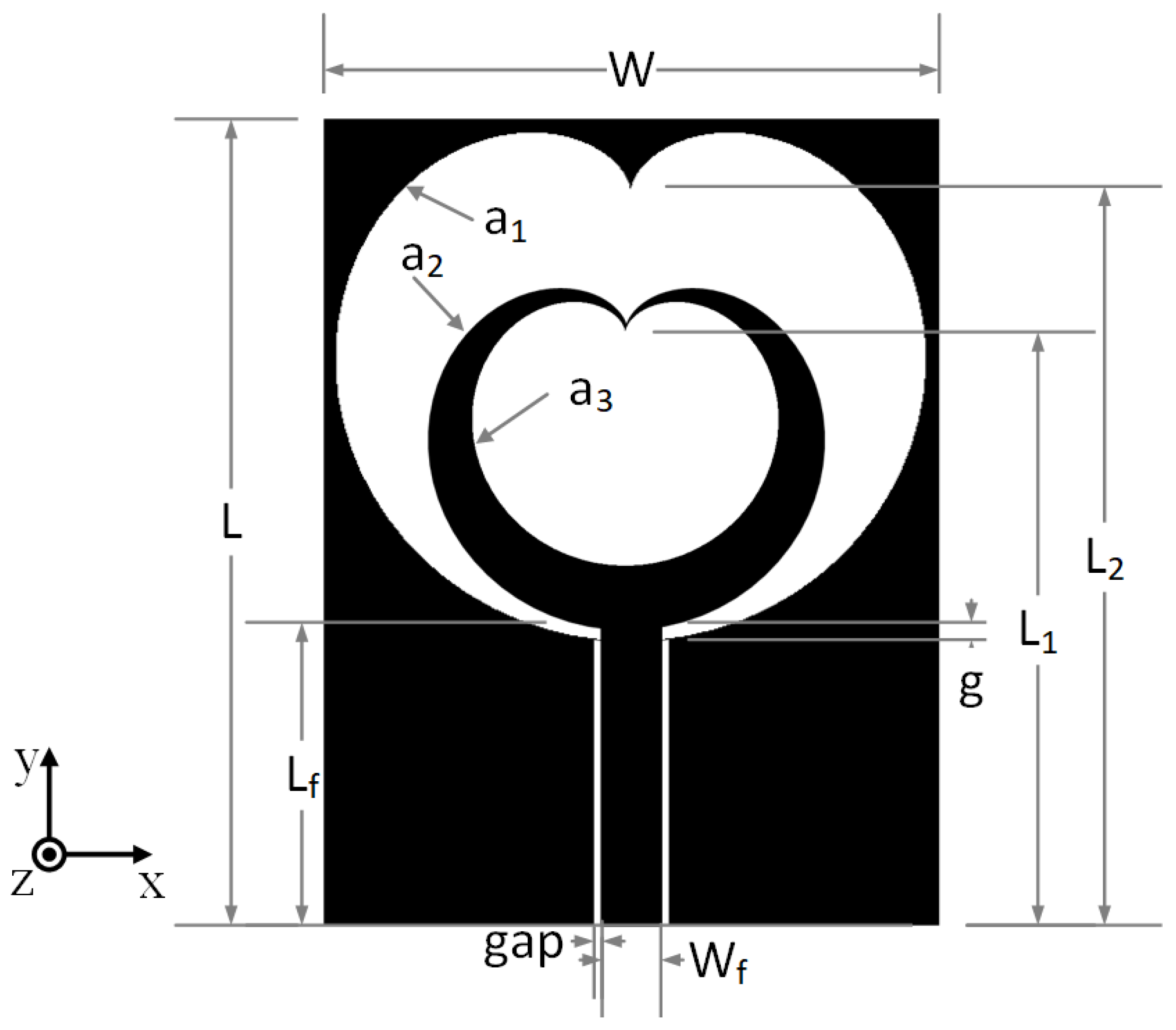
2. Proposed Antenna and Parametric Sweep

Numerous shapes of fractal antennas can be found in the literature, while those that satisfy the shapes of mathematical curves are particularly important.
The antenna structure presented here is based on a slot in the form of more self-similar nested cardioids. The standard parametric mathematical expression for cardioid is the following [31,32]:
x ( φ ) = a cos φ ( 1 cos φ ) y ( φ ) = a sin φ ( 1 cos φ ) 0 φ 2 π
where the parameter a scales the cardioids to the desired dimension. The proposed antenna has three cardioids that define its structure. Their scaling parameters, according to Equation (1), are a 1 , a 2 and a 3 , as seen in Figure 1.
The fractal shapes are characterized by two parameters: the iteration order (IO) and iteration factor (IF) [23]. The iteration order represents the number of fractal iterations, while the iteration factor represents the ratio of the dimensions of the second and first iterations of fractals. The iteration factor is always less than one because the last fractal dimension is always smaller than the previous one due to nested fractal geometry. Generally, in the majority of the proposed fractal antennas, the IF is the same for each iteration. However, in this paper, we propose a fractal antenna where the IF changes for each subsequent iteration. In this case, we can define IF 0 , which represents the ratio between a 2 and a 1 and IF 1 , which represents the ratio between a 3 and a 2 . The IF for the zeroth iteration of the realized antenna is IF 0 = a 2 / a 1 = 0.68 and the IF for the first iteration is IF 1 = a 3 / a 2 = 0.75. It provides additional flexibility in antenna design.
The antenna is designed for the FR-4 substrate of dielectric constant ε r = 4.3 and t a n δ = 0.025. The thickness of the substrate is 1.58 mm and the thickness of copper metallization is 0.018 mm. Parametric analysis was performed in order to obtain the maximum antenna impedance bandwidth; thus, the antenna can be used in energy harvesting applications without a lossy matching circuit between the antenna and detector. Simulations are performed in the time domain-based CST solver.
The overall dimensions of the antenna are 35 mm × 47 mm × 1.61 mm, which classifies this antenna into a group of electrically small antennas [33]. The geometry of the proposed antenna is shown in Figure 1.

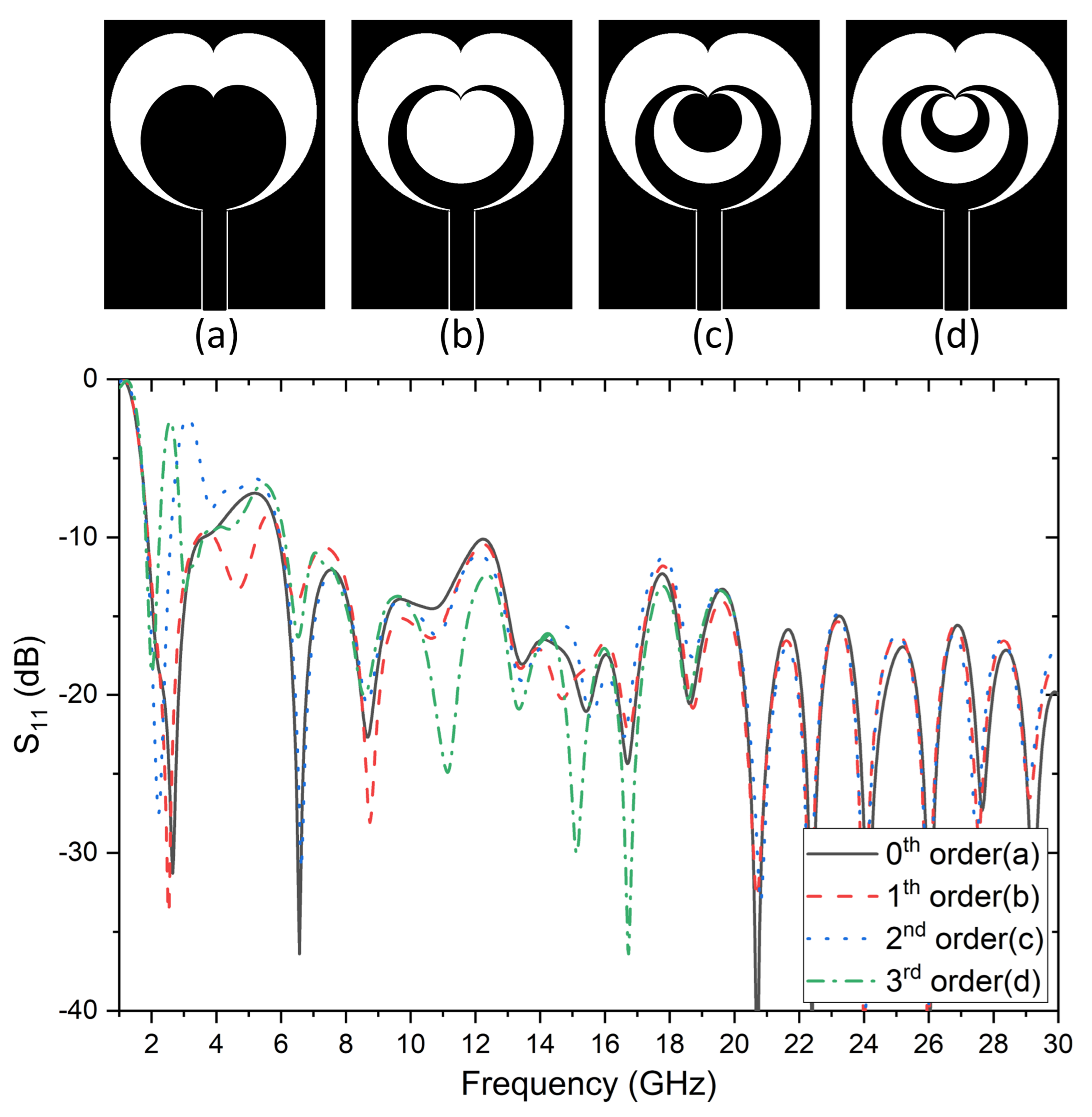
2.1. Effects of Different Antenna Iteration Orders

Figure 2 shows the procedure for constructing a cardioid fractal slot antenna with different iteration orders (and similarly to a majority of fractals with the same IF). The generator shape for this fractal antenna is a cardioid described by Equation (1). The starting point for this antenna is the zeroth iteration fractal, i.e., the cardioid antenna shown on Figure 2a. Additionally, this figure shows the generation of the fractal structure in which each iteration has the same iteration factor IF = 0.68 (IF = a 2 / a 1 = a 3 / a 2 = a 4 / a 3 = a 5 / a 4 ).
When examining the reflection coefficient of the antenna with zeroth iteration order and the antenna with the first iteration order seen in Figure 2b, it is observable that the cardioid in Figure 2b has a wider operating range. If the condition for the antenna operating range is taken to be S 11 < −10 dB, in the case of the zeroth iteration, this condition is fulfilled in two frequency bands: 1.8–3.5 GHz and 5.9–30 GHz, with the antennas having second and third iteration orders where the condition is met in a narrower band 1.8–2.57 GHz. The best characteristic in terms of broadband operation was obtained with a cardioid with the first iteration order (Figure 2c), whereas the S 11 characteristic deteriorates by further increasing the iteration order, as is the case of a cardioid with the second and third iteration order (Figure 2d).
By analyzing the results of simulations as well as fractal geometry that can be found in the literature, it was decided that the proposed antenna should be designed using fractal geometry, which changes the iteration factor in each subsequent iteration. In this manner, greater flexibility in design is achieved.

2.2. Effects of the Iteration Factor

When designing the antenna, it was determined that the parameter a 1 and the overall dimensions of the antenna (W × L) affect the position of the lowest resonant frequency where S 11 < −10 dB. Parameter a 1 is set at 6.6 so that the lowest frequency would be 1.8 GHz.
Furthermore, we can observe the effect of changing the iteration factor on antenna performance. IF 1 when defined as the ratio of a 3 / a 2 can be changed in two ways—either by changing a 2 while a 3 remains constant or by changing a 3 while a 2 remains constant.

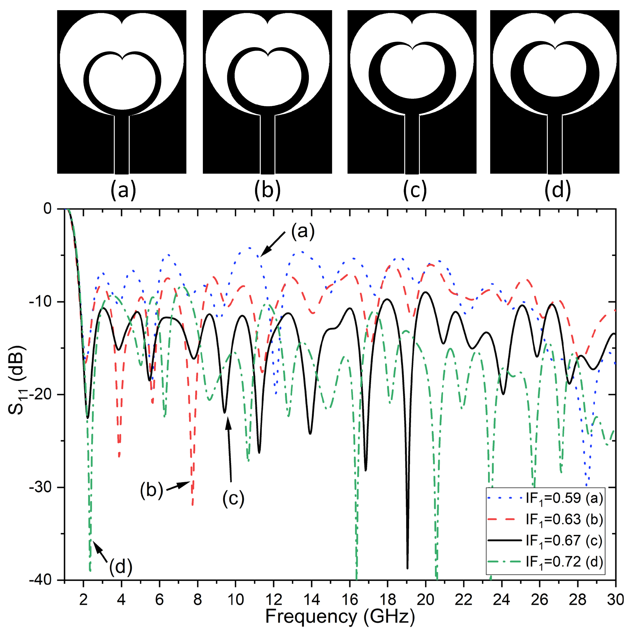
2.2.1. Effects of the Parameter a 2

The influence of dimension a 2 , i.e., different values of IF 1 = a 3 / a 2 , on the S 11 parameters when the parameters a 1 = 6.6 and a 3 = 3.4 are constant, is shown in Figure 3.
A change in the value of parameter a 2 has a significant impact on the resonant frequency position above 2 GHz and the S 11 level throughout the entire band. The best results in this parameter range are achieved with a 2 = 4.45 (IF 1 = 0.67). Such a big influence of parameter a 2 on S 11 is characteristic of the antenna, and it can be explained by the fact that, by changing a 2 , two iteration factors are changing at the same time: IF 0 = a 2 / a 1 and IF 1 = a 3 / a 2 .

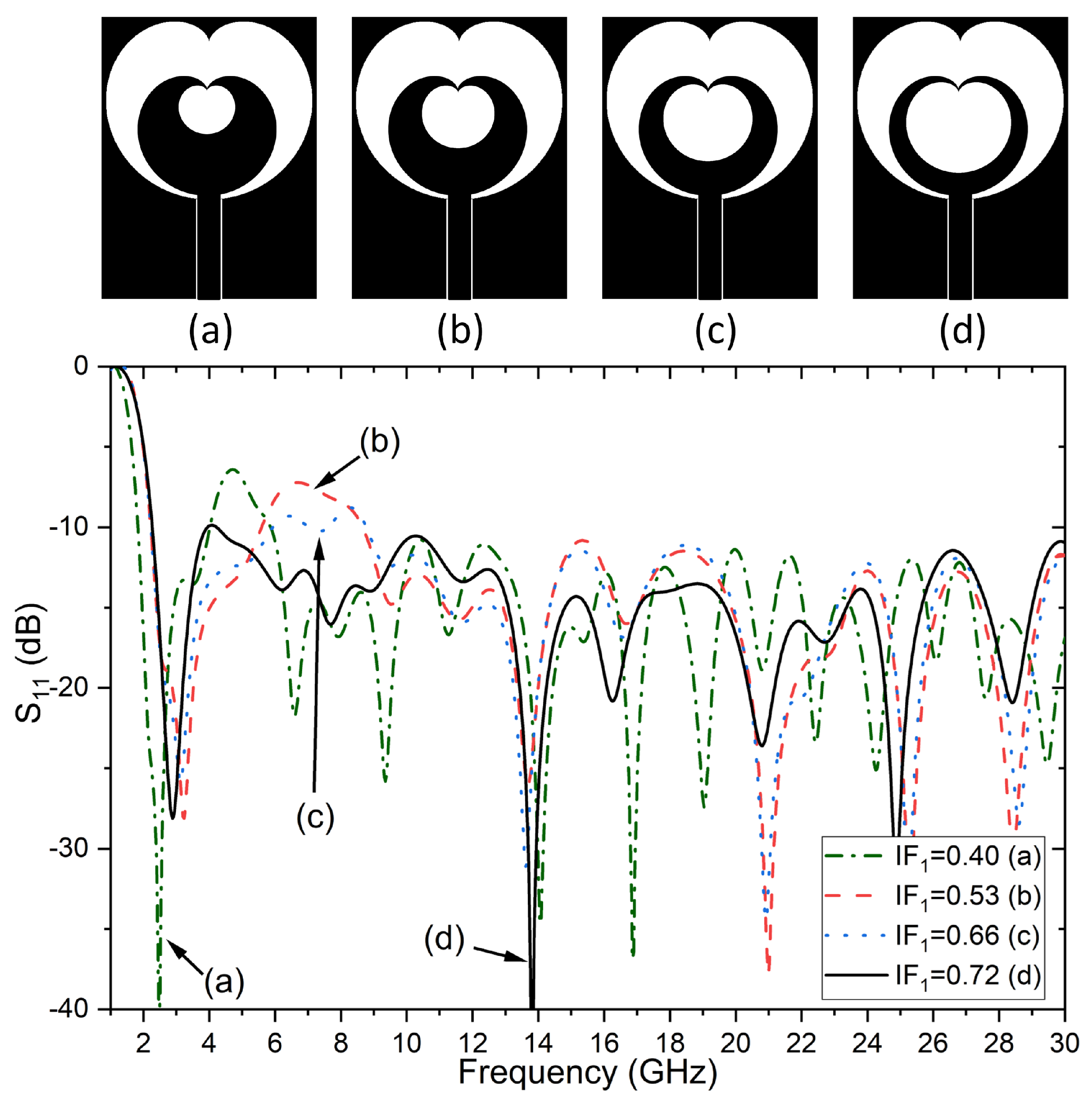
2.2.2. Effects of the Parameter a 3

In further analysis, the parameters a 1 and a 2 are kept constant while the a 3 parameter was changed until the desired criteria were met. The influences of dimension a 3 , i.e., different IF 1 = a 3 / a 2 , on the S 11 parameter when the parameters are set at a 1 = 6.6 and a 2 = 4.55 are constant, and they are shown in Figure 4.
Figure 4 shows that, in this scenario, for the iteration factor IF 1 = 0.72, the S 11 characteristic is below −10 dB in the widest frequency range. Based on the results shown in Figure 2, Figure 3 and Figure 4, a noticeable advantage of the different IFs for each subsequent iteration can be observed. The proposed method increases the flexibility of the design and the ability to meet more antenna requirements than in case with a fixed IF. In this manner, the antenna characteristics can be even further improved.

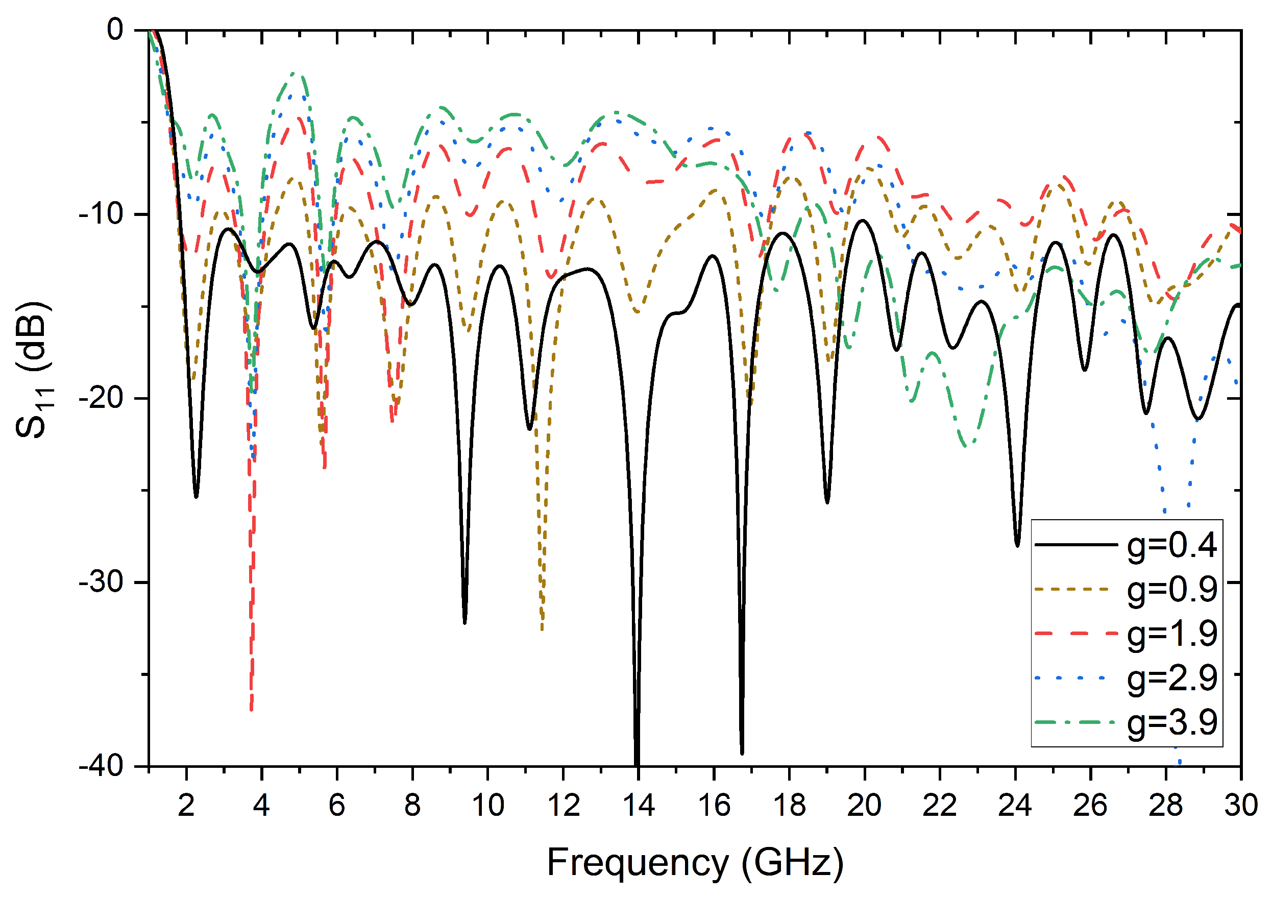
2.3. Effects of the Parameter g

The influence of dimension g at the point where the CPW line supplies the cardioid, on the reflection coefficient, is shown in Figure 5. It can be observed that the parameter g has a significant influence on the reflection coefficient level. The widest bandwidth characteristic is obtained when g = 0.4 mm, and further increases in the value of g considerably deteriorates the reflection coefficient in the entire operating band.

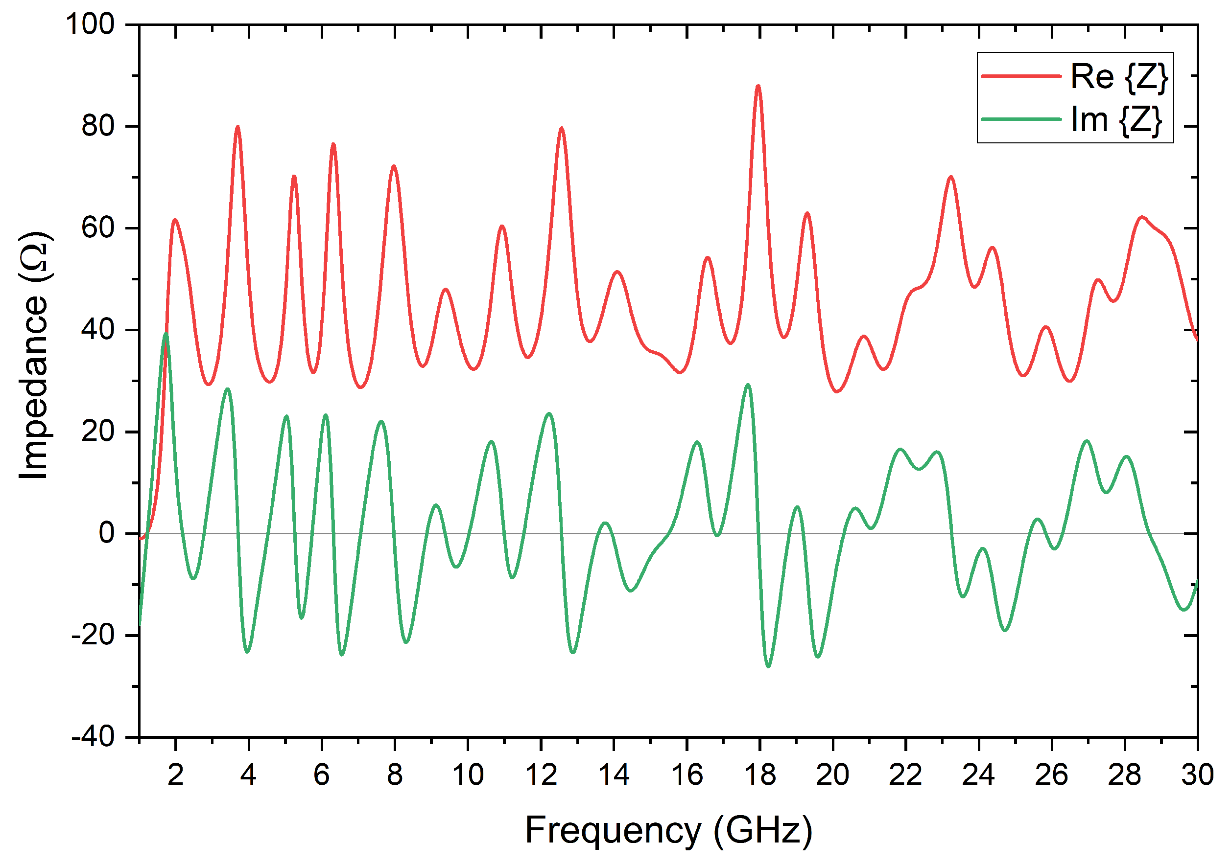
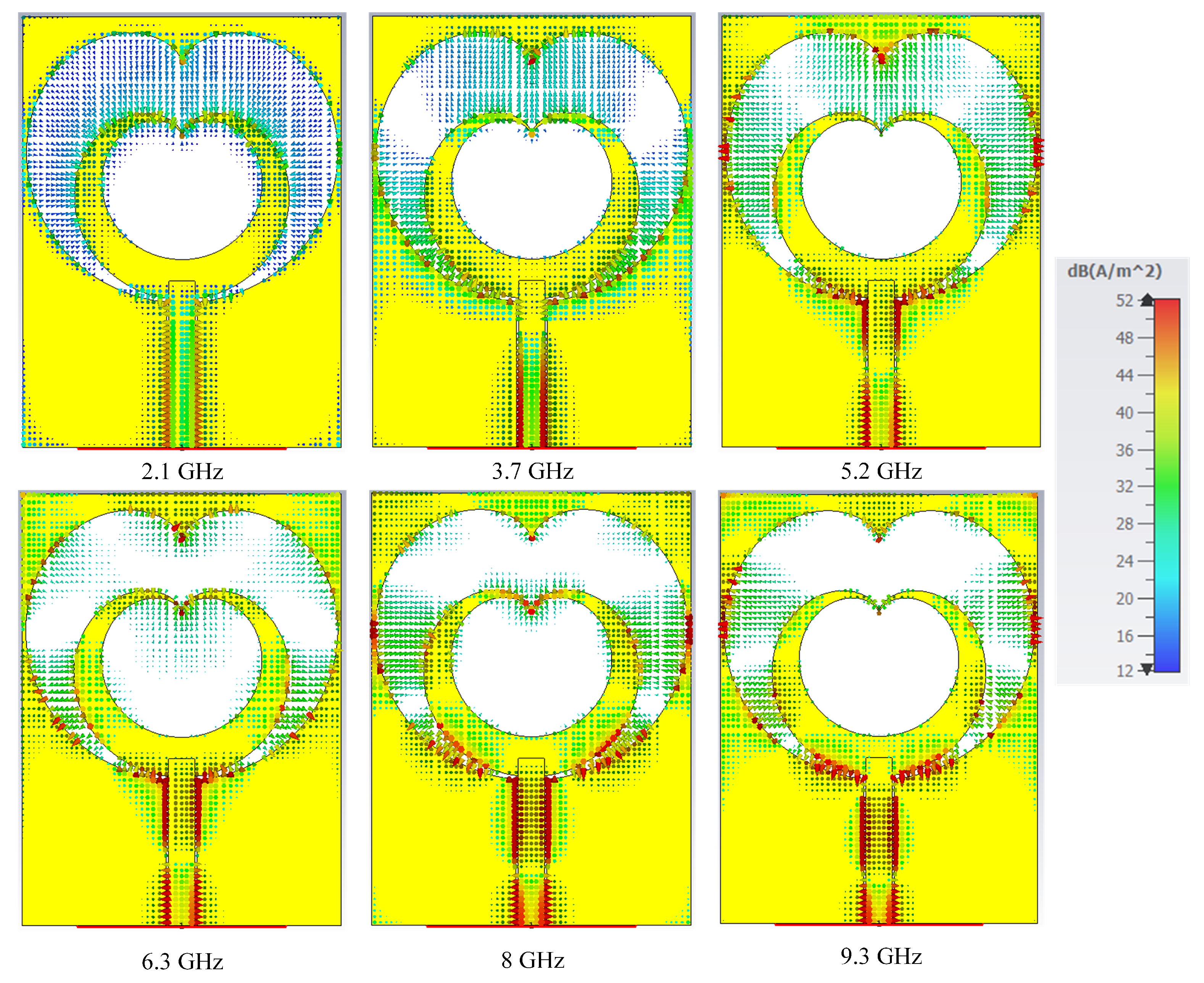
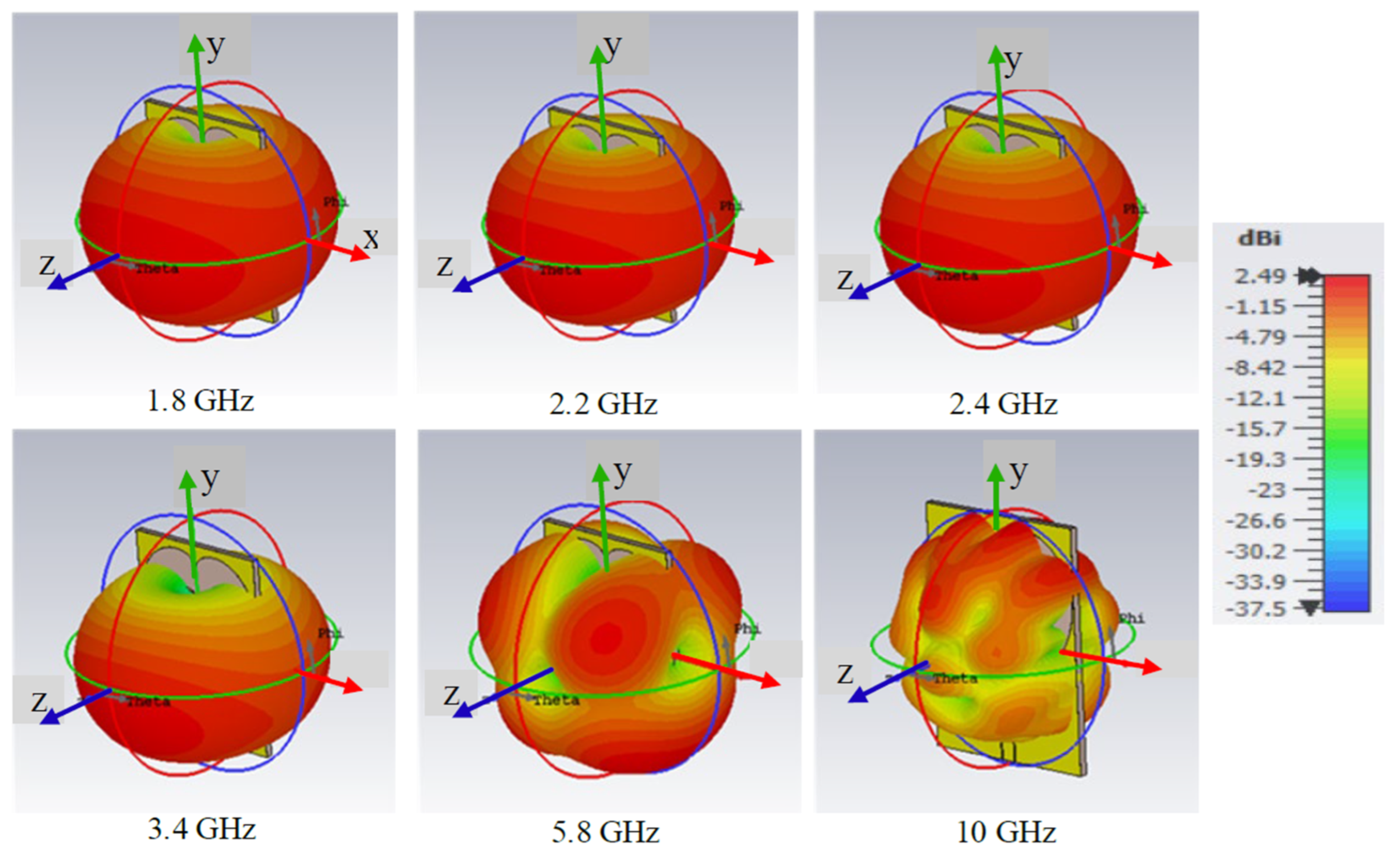
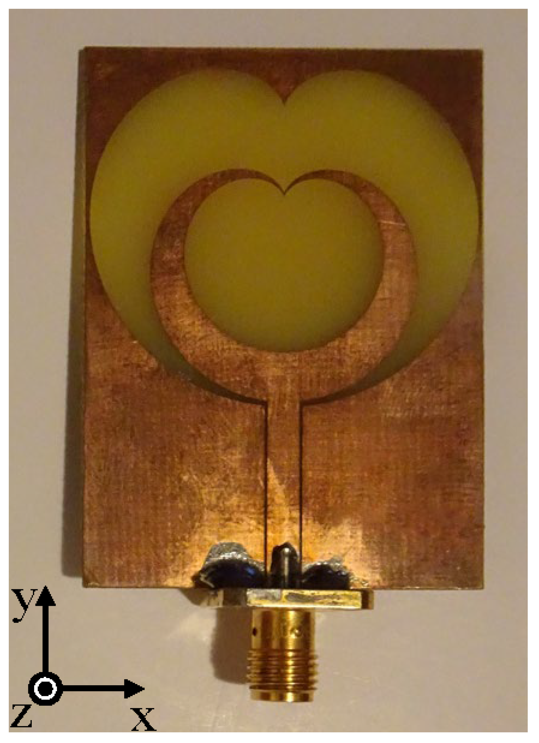
2.4. Characteristics of the Proposed Antenna

The simulated values of real and imaginary parts of the impedance of optimized antennas (Figure 1) are shown in Figure 6.
The results show a very narrow range of variation of the real part of the impedance of only 28–87 Ω , which is very useful for wideband energy harvesting applications.
The current density distribution at the first six antenna resonant frequencies, 2.1 GHz, 3.7 GHz, 5.2 GHz, 6.3 GHz, 8 GHz and 9.3 GHz, are shown in Figure 7.
Simulated radiation patterns of the proposed antenna in the E-planes and H-planes are provided in the following frequencies: 1.8 GHz, 2.2 GHz, 2.4 GHz, 3.4 GHz, 5.8 GHz, 10 GHz, 13 GHz, 17 GHz, 19 GHz, 24 GHz, 28 GHz and 30 GHz. They are shown in Figure 8.
Simulated 3D radiation patterns of the proposed antenna on frequencies 1.8 GHz, 2.2 GHz, 2.4 GHz, 3.4 GHz, 5.8 GHz and 10 GHz in the logaritmic scale are shown in Figure 9.

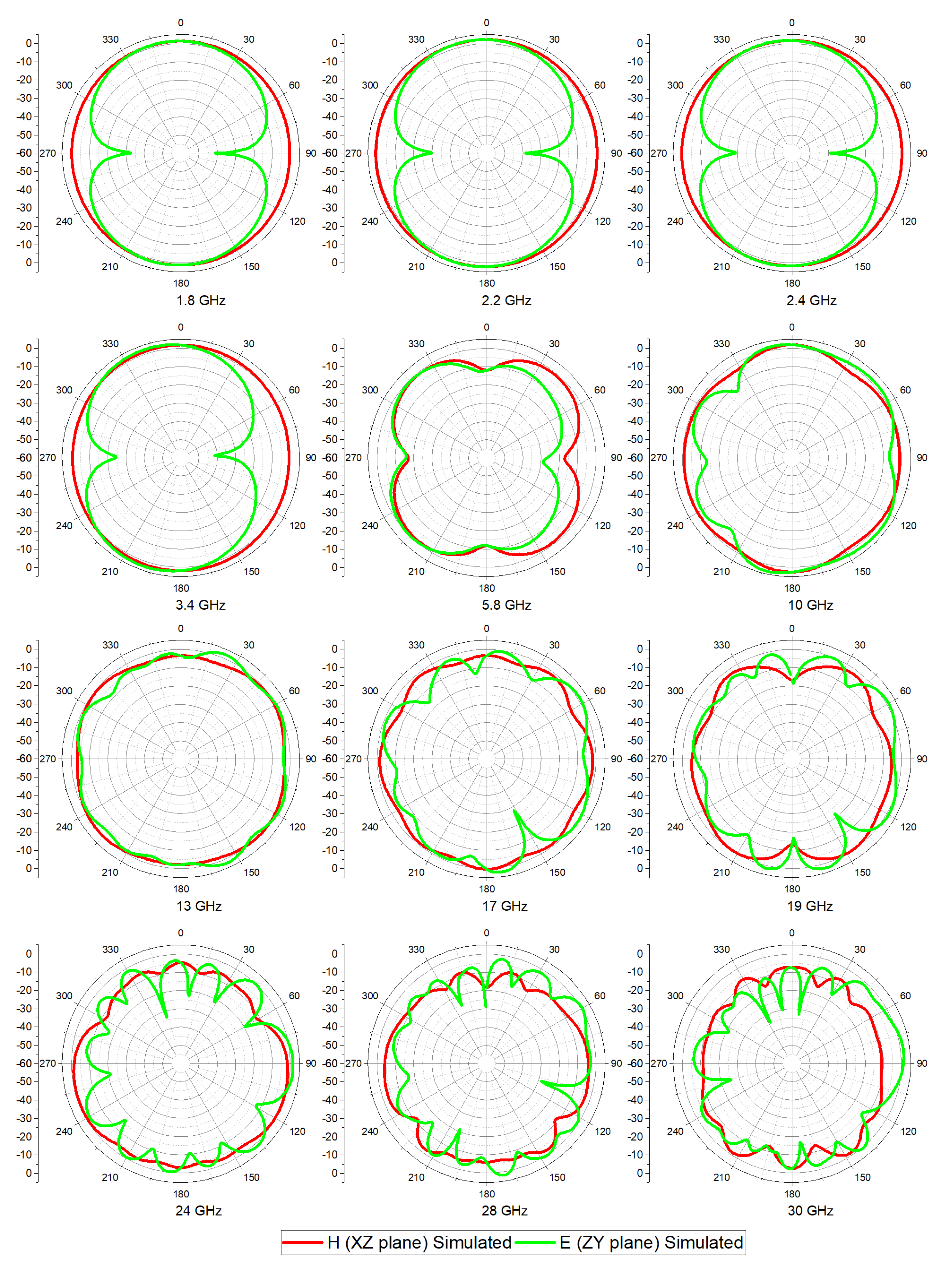
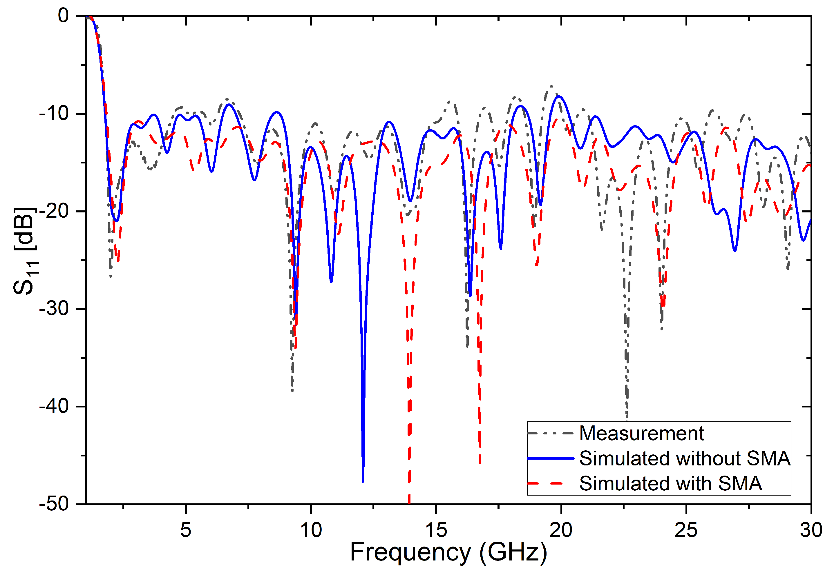
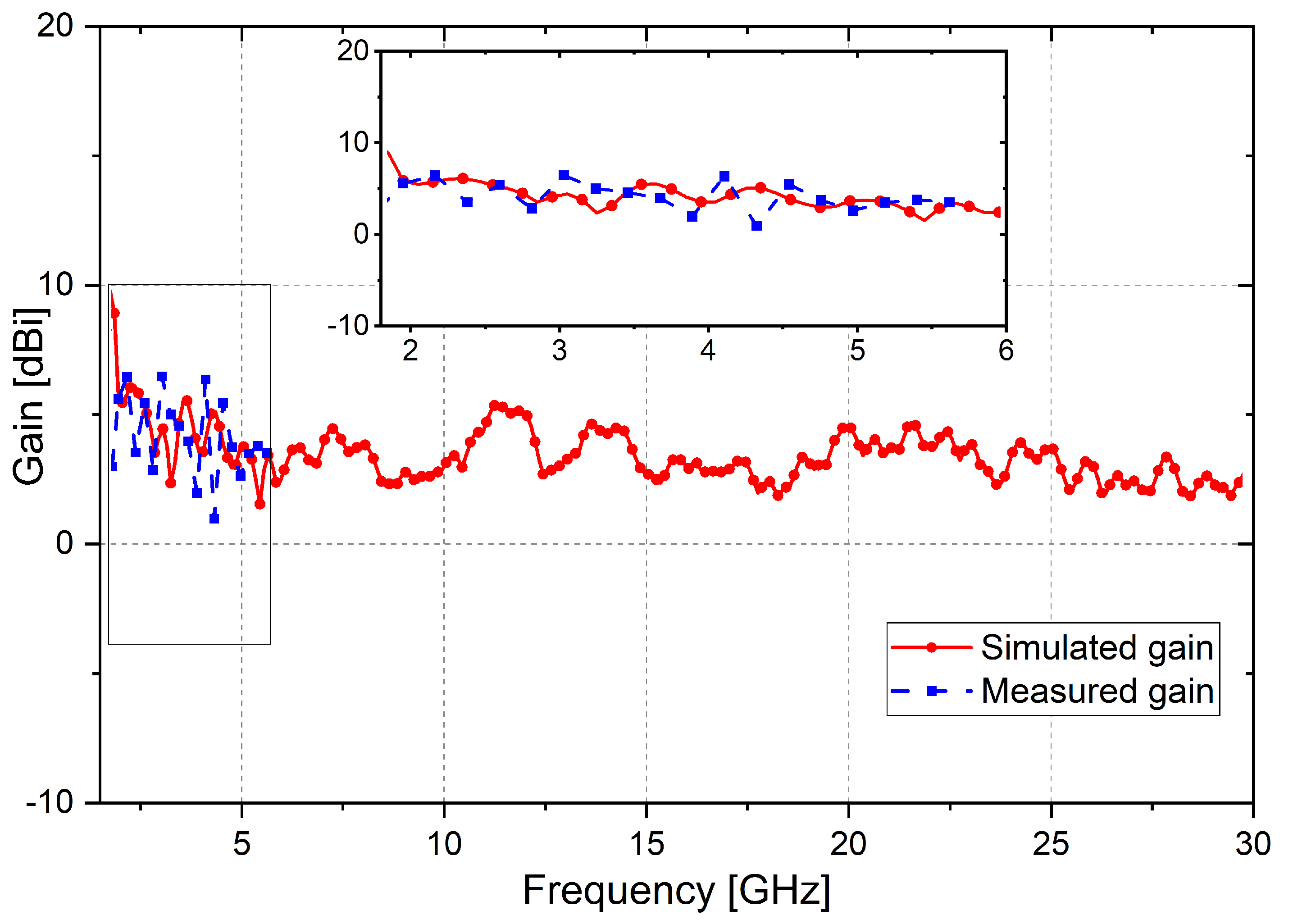
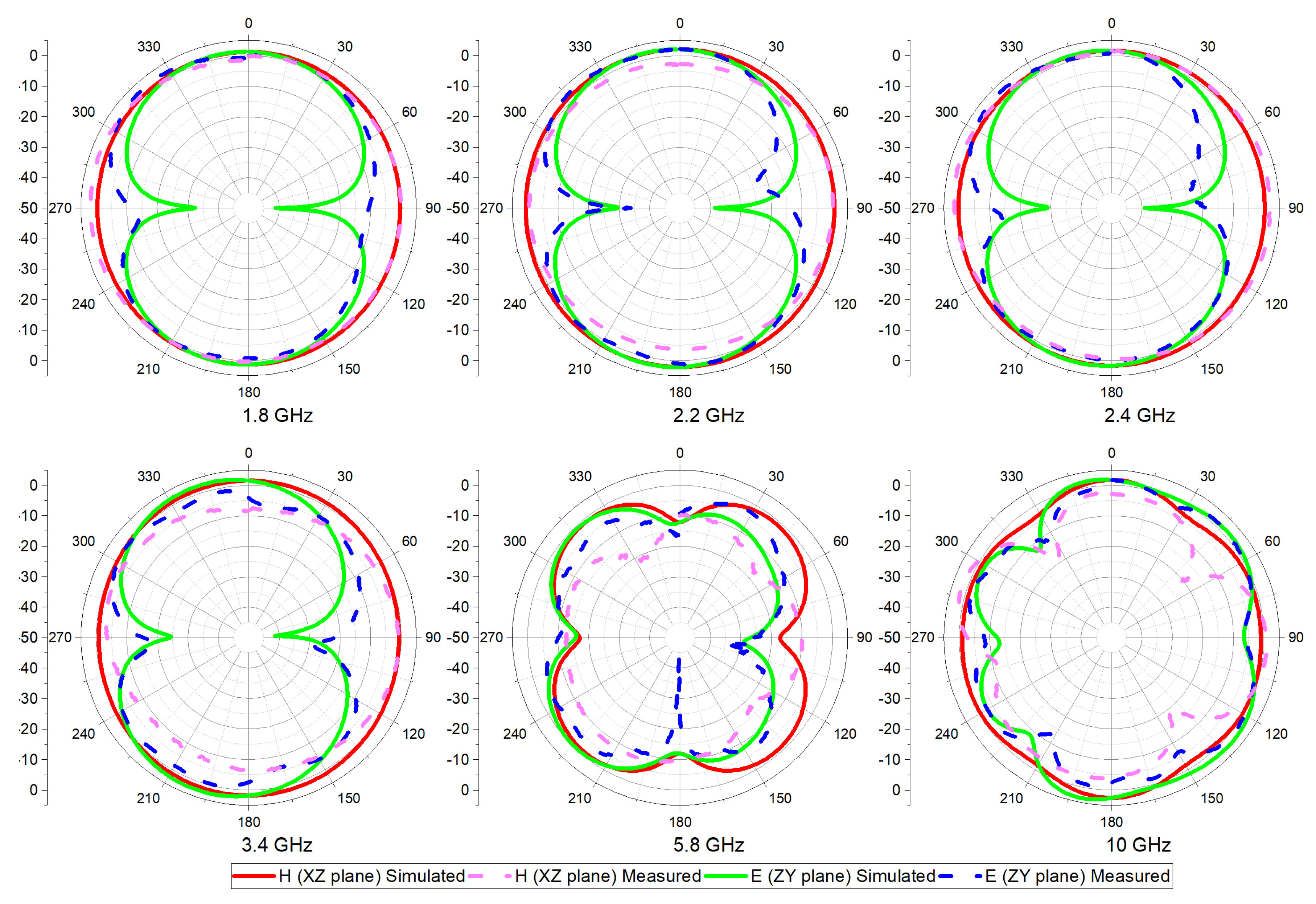
3. Experimental Results and Discussion

The antenna is manufactured using a simple photolithographic process, with a small deviation from the desired dimensions. Figure 10. shows the produced antenna on an FR-4 substrate with a coaxial SMA connector [34] at the input of the CPW line, which is declared for frequencies up to 27 GHz.
The antenna was measured using a vector network analyzer ANRITSU MS4647A. The reflection on the coaxial port of the antenna was obtained directly from the measurement results of the network analyzer. The maximum gain G R of the receiving antenna is obtained based on the Friis formula for the attenuation of free space:
G R = 20 l o g 10 d + 20 l o g 10 f + 20 l o g 10 4 π / c G T F S P L
where F S P L denotes free space attenuation; d denotes distance in meters; f denotes frequency; c denotes the speed of light in a vacuum; G T denotes the gain of the transmitting antenna; and G R denotes the gain of the receiving antenna. A ridge-horn antenna was used as a transmitting antenna.
The measured and simulated S 11 parameters are shown in Figure 11.
Some disagreement between measured and simulated results occur due to inaccuracies in manufacturing and because antenna simulations are performed without connectors. Moreover, the electromagnetic properties of a low-cost FR-4 laminate are not strictly controlled and may differ from one laminate board to another.
In order to remove doubt about the influence of the SMA connector on an antenna reflection coefficient above 27 GHz, the simulation was performed with an ideal excitation (waveguide port) and then with an SMA connector [34]. It can be observed from Figure 11 that there are differences in the reflection coefficient above 20 GHz but the reflection coefficient is below −10 dB with and without the connector. It is clear that the SMA connector, in this project, can be used up to 30 GHz without influencing the improvement of the reflection coefficient.
Figure 12 shows the results of measurements and simulations of the gain calculated by expression (2). The gain was only measured up to 6 GHz because the transmitting antenna is declared in that band.
The proposed antenna is compared with previously reported super wideband (SWB) antennas on FR-4 substrates in terms of operating bandwidth (BW), electrical dimensions and bandwidth dimension ratio (BDR). The results are shown in Table 1. The bandwidth dimension ratio indicates how large the operating bandwidth is as a percentage per antenna electrical area unit [23]:
B D R = B W % L f l o w × W f l o w
where L f l o w represents the electrical length and W f l o w represents the electrical width of the antenna calculated at the lower-end of operating band that meets the −10 dB return loss and B W % represents bandwidth in percentage calculated by the following formula:
B W % = 2 f h i g h f l o w / f h i g h + f l o w · 100 %
where f l o w and f h i g h represent the lower and higher frequencies of operating bands, respectively. A larger BDR indicates that the designed antenna is smaller in dimension and wider in bandwidth.
Figure 13 shows a comparison of simulated and measured radiation patterns in the E-plane and H-plane at the following frequencies: 1.8; 2.2; 2.4; 3.4, 5.8 and 10 GHz.
Based on the measurement results shown in Figure 13, a pretty good match of the simulated and measured radiation patterns can be noted. All measurements of the antenna radiation patterns are performed in free space, since the anechoic chamber is not available. Some discrepancies between measured and simulated results can be explained by this fact. It can be observed that the proposed antenna exhibits almost omnidirectional radiation patterns up to 5.8 GHz, which is wider than one octave (3.2:1). It is not possible to increase radiation pattern’s bandwidth without decreasing the impedance bandwidth. The design of this antenna was devoted to obtaining the maximum antenna impedance bandwidth because its primary purpose was energy harvesting. The one method to improve antenna radiation patterns at higher frequencies is to reduce antenna dimensions, but the impedance bandwidth will be reduced at low frequencies.

4. Conclusions

The original design of a broadband slot antenna is shown, which is suitable for mass and cheap production and can be used either as a separate device or integrated with other subdevices of a telecommunication system in the frequency range of 1.8–30 GHz (16:1). A parametric analysis was performed to obtain the widest possible impedance bandwidth in order to avoid a lossy matching circuit between the antenna and detector in energy harvesting systems. Simulation results show that, by using fractal geometry and the cardioid shape, the desired impedance matching, gain and efficiency are all achieved in ultra-wideband frequency ranges.
The antenna has small dimensions at only 35 mm × 47 mm (0.21 λ × 0.285 λ ) and exhibits a maximum BDR (bandwidth dimension ratio) of 3062 compared to the ones published in the literature so far. A larger BDR indicates that the designed antenna is smaller in dimension and wider in bandwidth. Simulated and measured results show that the antenna has a reflection coefficient, S11, below −10 dB in the entire 1.8 GHz to 30 GHz frequency range. The antenna exhibits gains up to 5 dBi. The measured radiation patterns on frequencies 1.8, 2.2, 2.4, 3.4, 5.8 and 10 GHz are presented.
The antenna is uniplanar and does not require any complicated photolithography procedures during fabrication. It is realized on a cheap FR-4 substrate and is fed by a CPW line; thus, it is very suitable for integration with diodes and transistors. This is very important since it is primarily intended for the broadband harvesting of electromagnetic energy and its conversion in direct currents for biasing low-power sensor networks. Antenna impedances have very small variations from 28 to 87 Ω , which is very convenient for use in recetennas without matching circuits. In addition to this basic purpose, the antenna can be used as a transceiver antenna for 3G, LTE, 5G, WLAN, RFID, Bluetooth, ISM, satellite communication and radars.

Author Contributions

Conceptualization, L.L. and B.J.; formal analysis, L.L., B.J., A.J. and V.R.; validation, L.L. and M.R.; writing—original draft preparation, L.L., B.J., A.J. and V.R.; writing—review and editing, L.L. and B.J. All authors have read and agreed to the published version of the manuscript.

Funding

This research received no external funding.

Conflicts of Interest

The authors declare no conflict of interest.

References

  1. Gu, X.; Burasa, P.; Hemour, S.; Wu, K. Recycling Ambient RF Energy: Far-Field Wireless Power Transfer and Harmonic Backscattering. IEEE Microw. Mag. 2021, 22, 60–78. [Google Scholar] [CrossRef]
  2. Piñuela, M.; Mitcheson, P.D.; Lucyszyn, S. Ambient RF energy harvesting in urban and semi-urban environments. IEEE Trans. Microw. Theory Technol. 2013, 61, 2715–2726. [Google Scholar] [CrossRef]
  3. Tavares, J.; Barroca, N.; Saraiva, H.M.; Borges, L.M.; Velez, F.J.; Loss, C.; Salvado, R.; Pinho, P.; Goncalves, R.; Carvalho, N.B. Spectrum opportunities for electromagnetic energy harvesting from 350 MHz to 3 GHz. In Proceedings of the 2013 7th International Symposium on Medical Information and Communication Technology (ISMICT), Tokyo, Japan, 6–8 March 2013; pp. 126–130. [Google Scholar]
  4. Divakaran, S.K.; Krishna, D.D.; Nasimuddin. RF energy harvesting systems: An overview and design issues. Int. J. RF Microw. Comput. Eng. 2019, 29, e21633. [Google Scholar] [CrossRef] [Green Version]
  5. Mrnka, M.; Vasina, P.; Kufa, M.; Hebelka, V.; Raida, Z. The RF Energy Harvesting Antennas Operating in Commercially Deployed Frequency Bands: A Comparative Study. Int. J. Antennas Propag. 2016, 2016, 7379624. [Google Scholar] [CrossRef] [Green Version]
  6. Shrestha, S.; Noh, S.-K.; Choi, D.-Y. Comparative Study of Antenna Designs for RF Energy Harvesting. Int. J. Antennas Propag. 2013, 2013, 385260. [Google Scholar] [CrossRef] [Green Version]
  7. Tran, L.-G.; Cha, H.-K.; Park, W.-T. RF power harvesting: A review on designing methodologies and applications. Micro Nano Syst. Lett. 2017, 5, 14. [Google Scholar] [CrossRef] [Green Version]
  8. Awais, Q.; Jin, Y.; Chattha, H.T.; Jamil, M.; Qiang, H.; Khawaja, B.A. A compact rectenna system with high conversion efficiency for wireless energy harvesting. IEEE Access 2018, 6, 35857–35866. [Google Scholar] [CrossRef]
  9. Falkenstein, E.; Roberg, M.; Popovic, Z. Low-Power Wireless Power Delivery. IEEE Trans. Microw. Theory Technol. 2012, 60, 2277–2286. [Google Scholar] [CrossRef]
  10. Takacs, A.; Aubert, H.; Charlot, S.; Fredon, S.; Despoisse, L. Compact rectenna for space application. In Proceedings of the 2014 IEEE MTT-S International Microwave Symposium (IMS2014), Tampa, FL, USA, 1–6 June 2014; pp. 1–4. [Google Scholar]
  11. Karaaslan, M.; Bağmancı, M.; Ünal, E.; Akgol, O.; Sabah, C. Microwave energy harvesting based on metamaterial absorbers with multi-layered square split rings for wireless communications. Opt. Commun. 2017, 392, 31–38. [Google Scholar] [CrossRef]
  12. Sağık, M.; Altıntaş, O.; Ünal, E.; Özdemir, E.; Demirci, M.; Çolak, Ş.; Karaaslan, M. Optimizing the Gain and Directivity of a Microstrip Antenna with Metamaterial Structures by Using Artificial Neural Network Approach. Wirel. Pers. Commun. 2021, 118, 109–124. [Google Scholar] [CrossRef]
  13. Alkurt, F.O.; Olcay, A.; Ahmet, A.; Mehmet, B.; Emin, U.; Oguzhan, A.; Kemal, D.; Muharrem, K.; Cumali, S. Antenna-based microwave absorber for imaging in the frequencies of 1.8, 2.45, and 5.8 GHz. Opt. Eng. 2018, 57, 1. [Google Scholar] [CrossRef]
  14. Ladan, S.; Guntupalli, A.B.; Wu, K. A High-Efficiency 24 GHz Rectenna Development Towards Millimeter-Wave Energy Harvesting and Wireless Power Transmission. IEEE Trans. Circuits Syst. I 2014, 61, 3358–3366. [Google Scholar] [CrossRef]
  15. Mavaddat, A.; Armaki, S.H.M.; Erfanian, A.R. Millimeter-wave energy harvesting using 4 × 4 microstrip patch antenna array. IEEE Antennas Wirel. Propag. Lett. 2015, 14, 515–518. [Google Scholar] [CrossRef]
  16. Raut, H.D.; Shevada, L.; Malekar, R.; Kumar, S. High Gain Wideband Antennas for 5G Applications: A Review. In Inventive Communication and Computational Technologies; Springer: Singapore, 2021; pp. 777–787. [Google Scholar]
  17. Bindu, C.J.; Mridula, S.; Mohanan, P. Coplanar Waveguide Filter using Stub Resonators for Ultra Wide Band Applications. Procedia Comput. Sci. 2015, 46, 1230–1237. [Google Scholar] [CrossRef] [Green Version]
  18. Kulkarni, M.G.; Cheeran, A.N.; Ray, K.P.; Kakatkar, S.S. Coplanar waveguide band reject filter using electromagnetic band gap structure. Prog. Electromagn. Res. Lett. 2017, 70, 53–58. [Google Scholar] [CrossRef] [Green Version]
  19. Jaglan, N.; Kanaujia, B.K.; Gupta, S.D.; Srivastava, S. Design of band-notched antenna with DG-CEBG. Int. J. Electron. 2018, 105, 58–72. [Google Scholar] [CrossRef]
  20. Thakur, E.; Jaglan, N.; Gupta, S.D. Design of compact triple band-notched UWB MIMO antenna with TVC-EBG structure. J. Electromagn. Waves Appl. 2020, 34, 1601–1615. [Google Scholar] [CrossRef]
  21. Mao, C.X.; Zhang, Y.; Zhang, X.Y.; Xiao, P.; Wang, Y.; Gao, S. Filtering Antennas: Design Methods and Recent Developments. IEEE Microw. Mag. 2021, 22, 52–63. [Google Scholar] [CrossRef]
  22. Dastranj, A. Very small planar broadband monopole antenna with hybrid trapezoidal–elliptical radiator. IET Microw. Antennas Propag. 2017, 11, 542–547. [Google Scholar] [CrossRef]
  23. Chen, K.-R.; Sim, C.; Row, J.-S. A Compact Monopole Antenna for Super Wideband Applications. IEEE Antennas Wirel. Propag. Lett. 2011, 10, 488–491. [Google Scholar] [CrossRef]
  24. Kim, G.; Kim, S. Design and Analysis of Dual Polarized Broadband Microstrip Patch Antenna for 5G mmWave Antenna Module on FR4 Substrate. IEEE Access 2021, 9, 64306–64316. [Google Scholar] [CrossRef]
  25. Singhal, S.; Singh, A.K. CPW-fed hexagonal Sierpinski super wideband fractal antenna. IET Microw. Antennas Propag. 2016, 10, 1701–1707. [Google Scholar] [CrossRef]
  26. Gorai, A.; Karmakar, A.; Pal, M.; Ghatak, R. A CPW-Fed Propeller Shaped Monopole Antenna With Super Wideband Characteristics. Prog. Electromagn. Res. C 2013, 45, 125–135. [Google Scholar] [CrossRef] [Green Version]
  27. Oraizi, H.; Hedayati, S. Miniaturized UWB Monopole Microstrip Antenna Design by the Combination of Giusepe Peano and Sierpinski Carpet Fractals. IEEE Antennas Wirel. Propag. Lett. 2011, 10, 67–70. [Google Scholar] [CrossRef]
  28. Kumar, M.; Nath, V. Introducing multiband and wideband microstrip patch antennas using fractal geometries: Development in last decade. Wirel. Pers. Commun. 2018, 98, 2079–2105. [Google Scholar] [CrossRef]
  29. Rahman, N.; Islam, M.T.; Mahmud, Z.; Samsuzzaman, M. The Broken-Heart Printed Antenna for Ultrawideband Applications: Design and Characteristics Analysis. IEEE Antennas Propag. Mag. 2018, 60, 45–51. [Google Scholar] [CrossRef]
  30. Lazović, L.; Jokanovic, B.; Rubežić, V.; Jovanović, A. Printed Ultra-Wideband Cardioid Monopole Antenna for Energy Harvesting Application. In Proceedings of the TELSIKS 2019:14th International Conference on Advanced Technologies, Systems and Services in Telecommunications (TELSIKS): Proceedings of Papers, Niš, Serbia, 23–25 October 2019. [Google Scholar]
  31. Pourahmadazar, J.; Ghobadi, C.; Nourinia, J.; Shirzad, H. Multiband ring fractal monopole antenna for mobile devices. IEEE Antennas Wirel. Propag. Lett. 2010, 9, 863–866. [Google Scholar] [CrossRef]
  32. Abbena, A.G.E.; Salamon, S. Modern Differential Geometry of Curves and Surfaces with Mathematica, 3rd ed.; Chapman and Hall/CRC Press: Boca Raton, FL, USA, 2006. [Google Scholar]
  33. Lazovic, L.; Jokanovic, B.; Rubezc, V.; Jovanovic, A. Uniplanar Ultra-Wideband Cardioid Slot Antenna for Energy Harvesting Application. In Proceedings of the 2019 27th Telecommunications Forum (TELFOR), Belgrade, Serbia, 26–27 November 2019; pp. 1–4. [Google Scholar]
  34. Telegartner. End Launch SMA Jack, 27 GHz. 100024743 Datasheet. July 2019. Available online: https://www.telegaertner.com/fileadmin/pdms_files/J01151A1401KP.PDF (accessed on 1 February 2022).
  35. Tang, M.C.; Ziolkowski, R.W.; Xiao, S. Compact hyper-band printed slot antenna with stable radiation properties. IEEE Trans. Antennas Propag. 2014, 62, 2962–2969. [Google Scholar] [CrossRef]
  36. Deng, C.; Xie, Y.J.; Li, P. CPW-fed planar printed monopole antenna with impedance bandwidth enhanced. IEEE Antennas Wirel. Propag. Lett. 2009, 8, 1394–1397. [Google Scholar] [CrossRef]
  37. Ghaderi, M.R.; Mohajeri, F. A compact hexagonal wide-slot antenna with microstrip-fed monopole for UWB application. IEEE Antennas Wirel. Propag. Lett. 2011, 10, 682–685. [Google Scholar] [CrossRef]
  38. Azim, R.; Islam, M.T.; Misran, N. Compact tapered-shape slot antenna for UWB applications. IEEE Antennas Wirel. Propag. Lett. 2011, 10, 1190–1193. [Google Scholar] [CrossRef]
Figure 1. The geometry of the proposed fractal antenna. The metal is shown in black. Relevant dimensions of the antenna are as follows: W = 35.1 mm, L = 47.5 mm, gap = 0.25 mm, W f = 2.85 mm, L f = 16.4 mm, g = 0.40 mm, L 1 = 34.45 mm (distance from the cardioid center), L 2 = 42.43 mm, a 1 = 6.6, a 2 = 4.68 and a 3 = 3.4.
Electronics 11 01043 g001
Figure 2. Simulated reflection coefficients for the fractal antenna geometries with different iteration orders. (a) 0th iteration order; (b) 1th iteration order; (c) 2nd iteration order; (d) 3rd iteration order.
Electronics 11 01043 g002
Figure 3. The simulated reflection coefficients of the first order fractal antenna for different iteration factors IF 1 = a 3 / a 2 obtained by changing the value of parameter a 2 : (a) a 2 = 3.91, (b) a 2 = 4.18, (c) a 2 = 4.45 and (d) a 2 = 4.72. The parameters are a 1 = 6.6 and a 3 = 3.4.
Electronics 11 01043 g003
Figure 4. The simulated reflection coefficients of the first order fractal antenna for different iteration factors IF 1 = a 3 / a 2 obtained by changing the value of parameter a 3 when a 1 = 6.6 and a 2 = 4.55: (a) a 3 = 3.64, (b) a 3 = 4.82, (c) a 3 = 6.06 and (d) a 3 = 6.55.
Electronics 11 01043 g004
Figure 5. The simulated reflection coefficients for different values of distance g.
Electronics 11 01043 g005
Figure 6. Simulated impedance of the proposed antenna.
Electronics 11 01043 g006
Figure 7. Current density distribution over the antenna surface at a few resonant frequencies.
Electronics 11 01043 g007
Figure 8. Simulated radiation patterns of the antenna in the E-plane and H-plane.
Electronics 11 01043 g008
Figure 9. Three-dimensional representation of the simulated radiation patterns.
Electronics 11 01043 g009
Figure 10. Realized fractal antenna in the form of a cardioid with overall dimensions of 35 mm × 47 mm.
Electronics 11 01043 g010
Figure 11. Comparison of the measured and simulated reflection coefficients of the antenna with and without SMA connector.
Electronics 11 01043 g011
Figure 12. Measured and simulated gain of the proposed antenna.
Electronics 11 01043 g012
Figure 13. Measured and simulated radiation patterns in the E-plane and H-plane.
Electronics 11 01043 g013
Table 1. Comparison of the SWB antenna structures fabricated on FR-4 substrates in terms of various parameters.
ReferenceFreq. Range (GHz)BW:1BW %Electrical Dimensions 1BDR
[23]1.4–18.813.0:1172%0.17  λ  × 0.37  λ 2762.7
[25]3.4–37.411.0:1167%0.32  λ  × 0.34  λ 1544.7
[29]2.9–10.73.6:1115%0.16  λ  × 0.29  λ 2406.9
[26]3–3511.6:1168%0.38  λ  × 0.55  λ 805.84
[35]2.2–22.19.8:1163%0.30  λ  × 0.23  λ 2393.7
[36]2.4–24.310.1:1164%0.18  λ  × 0.33  λ 2718.1
[37]2.9–186.2:1144%0.29  λ  × 0.29  λ 1718.2
[38]3–11.23.7:1115%0.22  λ  × 0.24  λ 2187.4
Proposed1.8–3016.9:1178%0.21  λ  × 0.28  λ 3062.1
1 Electrical dimensions are calculated relative to the lowest frequency in the band.
Publisher’s Note: MDPI stays neutral with regard to jurisdictional claims in published maps and institutional affiliations.

