Article

A Novel ISO 26262-Compliant Test Bench to Assess the Diagnostic Coverage of Software Hardening Techniques against Digital Components Random Hardware Failures

1
Department of Control and Computer Engineering, Politecnico di Torino, 10129 Turin, Italy
2
Huawei Pisa Research Center, 56121 Pisa, Italy
*
Author to whom correspondence should be addressed.
Electronics 2022, 11(6), 901; https://doi.org/10.3390/electronics11060901
Submission received: 9 February 2022 / Revised: 5 March 2022 / Accepted: 12 March 2022 / Published: 14 March 2022
(This article belongs to the Section Electrical and Autonomous Vehicles)

Abstract

:
This paper describes a novel approach to assess detection mechanisms and their diagnostic coverage, implemented using embedded software, designed to identify random hardware failures affecting digital components. In the literature, many proposals adopting fault injection methods are available, with most of them focusing on transient faults and not considering the functional safety standards requirements. This kind of proposal can benefit developers involved in the automotive market, where strict safety and cost requirements make the adoption of software-only strategies convenient. Hence, we have focused our efforts on compliance with the ISO 26262 automotive functional safety standard. The approach concerns permanent faults affecting microcontrollers and it provides a mapping between the failure mode described in part 11 of the Standard and the chosen fault models. We propose a test bench designed to inject permanent failures into an emulated microcontroller and determine which of them are detected by the embedded software. The main contribution of this paper is a novel fault injection manager integrated with the open-source software GCC, GDB, and QEMU. This test bench manages all the assessment phases, from fault generation to fault injection and the ISA emulation management, up to the classification of the simulation results.

1. Introduction

Nowadays, the growing complexity of the embedded systems employed in different industries to implement safety or mission-critical applications, such as the aerospace, automotive, and defense industries, has increased the interest in making them more reliable. The number of safety-related systems installed inside vehicles is steadily growing within the automotive industry. Due to the nature of these systems, it is vital to prove that they implement the correct functionality with sufficient safety.
When dealing with safety-critical systems, it is necessary to develop them in compliance with international functional safety standards. Functional safety is a part of the overall safety of a product or process, focusing in particular on guaranteeing that the system can perform its task without unreasonable risks related to the electrical and electronics (E/E) devices, and hence in a correct way and within the specified time constraints (in a hard real-time system), or at least that it can bring the controlled physical process into a safe state. All the current functional safety standards are derived from IEC 61508. In particular, the one to be followed for automotive applications is ISO 26262.
To guarantee that such systems do not expose their users to an unacceptable level of risk, they must be developed to be reliable. For the sake of this paper, the meaning of reliability is twofold. The first consideration is the absence of systematic design errors, whereas the second is hardening the system against random hardware failures (RHFs).
In general, hardening the system means adding a sort of redundancy, implemented in the hardware, by adding extra components, or in the software. In any case, the goal is to guarantee that any RHF affecting the system will not cause dangerous misbehavior. Software strategies rely on statements to monitor the correct execution of the payload application.
In cases in which both methods are equivalent from the safety point of view, a general rule is that since hardened components are more expensive with respect to their other counterparts, it is more convenient to adopt a hardware approach in those cases where the design has to be produced in a small number of pieces. It is possible to buy hardened hardware in a commercial-off-the-shelf (COTS) form, reducing development costs. However, when the design has to be produced in many pieces, the software strategy is preferable. This approach allows one to buy cheaper hardware components, and it is possible to split the high cost of developing the software across the entire the production effort.
Considering automotive applications characterized by significant production volumes, software strategies are preferable. However, although hardware hardening components are sold with a type of certification that makes it possible to assume that they have a certain reliability level under certain assumptions (contained in the safety manual), as will be described in Section 2.2, software-implemented hardening methods must be tested inside the specific application context.
For this purpose, the critical point is to assess the method’s performance in RHF detection, referred to in the ISO 26262 standard as diagnostic coverage.
Herein, we propose a novel test bench to aid developers in this assessment process, injecting permanent failures into an emulated microcontroller. Its core is a fault injection manager (FIM) integrated with the open-source software GCC, GDB, and QEMU. This test bench manages all the assessment phases from fault generation to fault injection, as well as performing the instruction set architecture (ISA) emulation management, up to the classification of the simulation results.
Moreover, we focused our efforts on compliance with the ISO 26262 automotive functional safety standard, by providing a mapping between the failure modes described in part 11 of the Standard and the chosen fault models.
The rest of the paper is organized as follows.
Section 2 presents the state of the art. Section 2.1 focuses on fault injection, whereas Section 2.2 provides a brief description of the ISO 26262 standard.
Section 3 describes the proposal, focusing on the implemented fault models and their mapping with the ISO 26262 in Section 3.1 and on the test bench in Section 3.2.
Finally, Section 4 draws some conclusions.

2. State of the Art

2.1. Fault Injection

According to FIDES/UTEC 80 811:2011 and [1], a fault is the adjudged or hypothesized cause of an incorrect system state, which is called an error. A failure is an event that occurs when an incorrect service is delivered or, in other words, it is an error perceived by users or external systems.
Fault injection (FI) techniques to investigate the effect of random hardware failures have been studied over the years. Several methodologies have been proposed for this purpose, and numerous tools have been developed.
Some of them are hardware-implemented: fault injection is performed with physical tools such as an external power supply or a neutron beam on the item to modify a physical parameter within it (such as a voltage or current).
These techniques can be costly (for example, the use of neutron beams is usually possible only to investigate the susceptibility of an entire technology (e.g., 45 nm) to radiation), and the use of lasers or the injection of voltages/currents requires other expensive experimental equipment and a high number of specimens.
Another weak point of these strategies is that they require the hardware implementation of the design.
In any case, physical manipulation is fundamental to determine failure mode rates (the ways or modes in which a component might fail) and probability distributions.
To overcome these weak points, especially regarding the costs and the need for hardware implementation, various simulation-based techniques have been proposed over the years.
Regardless of the kind of injection chosen to inject faults, it is necessary to define fault models.
These describe the fault that the system can experience during its operations. Three aspects define a fault model: what to inject, describing the kind of fault; when to inject; and where to inject, to determine the part of the system targeted by the injection.
According to [2] a fault injection system has to be composed of the following components: a controller, load generator, injector, monitor and, of course, a target.
The controller generates the commands, which are conveyed to the monitor, load generator, and the injector. The latter reads a faultload library and generates the fault description (a translation of the chosen fault model to be injected that is suitable for actually injecting it into the target).
The load generator reads the workload library and produces the input stimuli acting as the target input signals, whereas the monitor logs the readouts (target output signals) to produce the fault effects analysis. If the target implements a closed-loop control system, the load generator implements a physical or behavioral model of the controlled process hat is capable of reacting to the target control commands.
Fault injection requires the execution of several experiments (or runs), which form, alongside the fault models and the workload libraries, a fault injection campaign.
To assess the results of an experiment, readouts are usually compared to the ones obtained from fault-free experiments (referred to as golden or fault-free runs).
Other important characteristics of a proposal (in terms of the approach and adopted fault models) are representativeness, usability, and efficiency [3].
Representativeness is the ability of the faultload library to represent the real faults that the target will experience during operation. This indicates that the method will be able to provide appropriate stimuli to the target. From this point of view, it is fundamental to consider the types and distribution of injected corruptions and failure modes. The effectiveness of the injected corruption can be guaranteed by properly tuning the what, where, and when aspects of the chosen fault models to achieve a match between the models and real faults, whereas the types and distribution of failure modes have to be evaluated in terms of the capability of the chosen library to generate realistic failure modes and hence to evaluate the fault tolerance.
Usability is the ability to use FI on a new target system. It has been assessed by taking into account the system’s portability, in terms of the possibility to use the tool across different target systems; its intrusiveness, or the capability of the proposed approach not to introduce significant perturbations into the target, which can distort the results of the experiments; and its flexibility, in terms of modularity of the approach and possibility of customizing or adding newer fault models.
The efficiency can be defined considering the required number of experiments and the activation and propagation of injected faults/errors. The first is needed to minimize the required time and obtain a statistically significant evaluation of the system. At the same time, the second emerges since faults that are not propagated to errors and then to failures are latent by definition, so no further experimental results are needed to investigate their effects.
In our case, the goal is to perform verification of the various software-hardening techniques against RHFs, such as those in [4], in which this process was applied to verify the effectiveness of software-based self-testing techniques; in [5], in which FI was adopted to prove the effectiveness of the software testing libraries proposed by the authors for an automotive microcontroller, and in [6], in which this process was proposed as a way to determine the presence of on-line functionally-untestable faults.
Other applications have been proposed to demonstrate the effectiveness of software-based testing strategies for the on-line testing of artificial neural networks [7] and there is even a new trend in civil engineering to use them to monitor the health state of concrete composite materials [8]. Moreover, thanks to the adoption of two different abstraction levels, they have been used to assess the capability of the embedded software to control a complex mechatronic system to mitigate RHFs [9].
The proposal on which we based the development of the novel test bench presented herein is that of [10].
This paper proposes a fault-injection system based on QEMU to determine the effects of soft errors on embedded system behavior. This paper also proposes a flowchart for performing the injection and a description of the faults.

Simular Contributions on SIHFT

QEMU has already been adopted in the past by various scholars for the implementation of simulation-based fault injection systems at the ISA level, in particular to investigate software-implemented hardware fault tolerance (SIHFT).
QEMU (Quick Emulator) [11] is an open-source machine emulator and virtualizer, written by Fabrice Bellard.
It can be used for CPU emulation for user-level processes, enabling applications to run on an architecture that is different from the one for which they have been compiled.
The main reason that QEMU has been used in our proposal is to make the test bench agnostic with respect to the specific instruction set, since it can emulate many different ISAs.
Although the authors of [10] decided to modify the emulator to perform fault injection, our approach is not to intervene at this level but to focus only on how to implement fault injection via debugging instruments.
More recent work is presented in [12]. As in the latter study, the authors decided to modify QEMU. Their purpose was to verify the robustness of Linux v.4 syscalls against possible x86 CPU soft errors. To speed up the campaign, the authors chose to use GNU Parallel to execute more instances of QEMU, while improving its performance on multi-core systems.
On the other hand, the authors of [13] designed a system of which the purposes are similar to those of our system, but used Bochs, OpenOCD, and Gem5 as emulation systems.
In our proposal, neither QEMU nor GDB are modified. We made this choice for two main reasons.
The first one is to make the fault injection system capable of injecting in all the instruction set architectures, whereas the second is that, in this way, it is possible to leave room, in future improvements, to use these techniques for real hardware components as well by using external debug and trace tools.
The first reason is motivated by the high number of ISAs available in the microcontroller market, whereas the second is to allow the possibility of experimentally determining, through techniques such as hardware-in-the-loop, the timing overhead effects of the chosen hardening techniques when the hardened application runs in the target [14].

2.2. ISO 26262

ISO 26262 is a functional safety standard designed for automotive applications. It was released in 2011. The current edition is the second one, released in 2018 [15]. The core of this Standard is the safety lifecycle, which is a process to be followed to achieve functional safety. Its main idea is to prevent dangerous situations, hence avoiding systematic errors in the design. Furthermore, designers must guarantee these requirements when RHFs, which are impossible to avoid, affect the design.
The Standard refers to a design that performs one or more safety-related functions within a motor vehicle as an item.
Like all International Standard Organization (ISO) documents, ISO 26262 (the version released in 2018) is divided into parts. It is composed of 12 parts, and six of them describe the safety lifecycle.
Part 3, called the Concept Phase, focuses on hazard analysis and risk assessment, item definition, and the preparation of the functional safety concept (FSC), a document containing all the safety requirements described at the functional level. This document also defines the safety goals (SGs) for the considered item. For the concept phase, a simulation-based approach is proposed to aid in the processes of hazard analysis and risk assessment, and the interested reader can find details of this in [16].
Part 4, called product development at the system level, defines the technical safety concept (TSC) and technical safety requirements (TSR). TSC describes, as its name says, the safety requirements at the technical level. Moreover, safety validation and the system and item integration and testing are covered, such as the definitions of hardware/software interfaces (HSIs). HSI is the conceptual bridge between parts 5 and 6 of the Standard.
Part 5 describes the product development at the hardware level. It specifies the hardware safety requirements, how to design the hardware to prevent defects (design flaws), how to evaluate its architectural metrics, and outlines safety goal violations due to RHFs. Furthermore, it describes how to perform hardware integration and verification.
Part 6 focuses on the software safety requirements, its architectural design, and the design and implementation of the software units.
Part 7 describes the production, operation, service, and decommissioning of the item.
Part 11 contains guidelines on applying ISO 26262 to semiconductors.
For the sake of this work, we are interested in parts 5 and 11. In any case, the SIHFT algorithms shall be developed in compliance with Part 6.
Part 5 describes the failure mode, effects, and diagnostic analysis (FMEDA). The core idea of FMEDA is to quantify the effects of all the possible failure modes (FMs) that can affect the hardware design on the safety requirements of the considered item.
The interested reader can find a more detailed description of a fault injection system designed to perform FMEDA on discrete components installed on the PCB of the item in [17].
If an FM is not detected in every circumstance, it is possible to define its diagnostic coverage (DC), defined as the percentage where the FM is detected over all the conditions where it is present.
Thanks to the DC, it is possible to compute the rates based on the ISO 26262 classifications (latent, residual, single point and multi-point perceived) of the hardware design.
The experimental determination of the DC is the primary purpose, from an ISO 26262 perspective, of the test bench proposed in this paper.
Part 11 has been added to version 2018 of the Standard. As its title says, it contains guidelines on how to apply the analysis described in part 5 to the peculiarities of semiconductor components. In general, this part of the Standard provides hints to address failure modes and a corresponding analysis for digital and analog components, memories, programmable logic devices, and other silicon IPs used in automotive applications.
We highlight that the classifications obtained by the proposed approach cannot be used directly to compute the RHF metrics required by ISO 26262 part 5, since the probability distributions of the root causes have to be obtained from the safety manual provided by the digital component manufacturer, or from the literature [18].

3. Proposed Approach

The proposal of this paper places itself into a more extensive activity performed by our research group.
On the one hand, our main end goal is to define transformation rules to harden the code against the effects of possible RHFs but, to achieve this result, it is necessary to design a way to assess the performance of the proposed hardening strategies in terms of DC.

3.1. Fault Models

The fault models considered in the current version of the tool were obtained by analyzing table 30 contained in part 11 of the Standard.
This table contains a list of exemplary FMs for common IP blocks usually integrated into digital components. The contained element failures are modeled in terms of function omissions (not delivered when needed), commissions (executed when not needed), timing, and values (delivered with incorrect values).
It is composed of three columns: part/subpart (e.g., CPU, DMA, interrupt controller unit), function (the role of the part/subpart in the overall system functionality) and aspects to be considered for failure mode (a textual description of the considered part/subpart failure model, e.g., an omission of the CPU corresponds to a given instruction flow that has not been executed).
The current version of the FIM features two fault models: Permanent and PermanentStuckAt.
As described in Section 2.1, a fault model is described by three aspects, what to inject, when inject it, and where (target) to inject.
A Permanent fault is described in accordance with the definition commonly found in the literature relating to the analysis of errors generated by faults at the electrical or gate level [19], i.e., as the replacement of a bit inside the affected register or memory location word with a fixed value (permanently stuck at 0 or 1) from the moment of injection up to the end of the simulation.
It is neessary to specify which bits can be affected by the fault. These are indicated by the bits set to 1 inside a field which we decided to call bitPosMaks.
A PermanentStuckAt fault is described as an entire affected register, which remains permanently stuck at the value set in the bitPosMask field.
For both the fault models, at the moment, the target is the program counter (PC) register, whereas the injection time is defined as a rectangular probability distribution between a minimum and a maximum time (specified as the number of machine instructionsfrom the start of the application).
These two fault models can be mapped with with the failure modes (FMs) reported in table 30 of ISO 26262 part 11, concerning the central processing unit (CPU), the interrupt handling (INTH), the memory management unit (MMU), and the interrupt control unit (ICU). In italics we indicate the FM descriptions provided by the Standard, followed by the justification for the Permanent fault model (affecting the PC) found by the authors.
CPU:
  • CPU_FM1.1—given instruction flow(s) not executed (total omission) due to program counter hang up and CPU_FM1.2—given instruction flow(s) not executed (total omission) due to instruction fetch hang up:
    fault injected in the PC such that the control flow jumps to a location outside the program area or trigger a not handled exception. The program may enter an endless loop.
  • CPU_FM2—un-intended instruction(s) flow executed (commission):
    fault injected in the PC such that the control flow jumps inside the program area but to a wrong address, creating an instruction flow that is different to the intended one.
  • CPU_FM3—incorrect instruction flow timing (too early/late):
    Fault injected in the PC such that a few instructions of the original program flow are omitted, leading to early/late program termination.
  • CPU_FM4—incorrect instruction flow result:
    fault injected in the PC such that the control flow jumps inside the program area but creating an instruction flow different than the intended one leading to wrong results.
INTH:
  • CPU_INTH_FM1—ISR not executed (omission/too few):
    upon the interrupt request, the fault injected in the PC does not allow the execution of the ISR (the PC points to an address other than that of the ISR to be executed).
  • CPU_INTH_FM2—un-intended ISR execution (commission/too many):
    a fault has been injected into the PC such that the instruction flow is abnormally brought to enter an ISR.
  • CPU_INTH_FM3—delayed ISR execution (too early/late):
    upon an interrupt request, a fault injected in the PC brings the execution flow to an address before the ISR, where the memory is initialized with NOPs. The PC then advances up to the ISR address.
  • CPU_INTH_FM4—incorrect ISR execution (see CPU_ FM1/2/4):
    Fault injected in the PC such that the control flow jumps inside the program area but creates an instruction flow that is different from the intended one.
ICU:
  • ICU_FM1— Interrupt request to CPU missing:
    upon an interrupt request, the fault injected in the PC does not allow the execution of the ISR (the PC points to an address other than that of the ISR to be executed).
  • ICU_FM2—Interrupt request to CPU without triggering event:
    fault injected in the PC such that the instruction flow is abnormally brought to enter an ISR.
  • ICU_FM3—Interrupt request too early/late:
    fault injected in the PC such that the instruction flow is abnormally brought to enter an ISR (too early). Upon the interrupt request, the fault injected in the PC brings the execution flow to an address before the ISR, where the memory is initialized with NOP. The PC then advances up to the ISR address (too late).
  • ICU_FM4: Interrupt request sent with incorrect data:
    fault injected in the PC such that a different ISR than the correct one is executed.
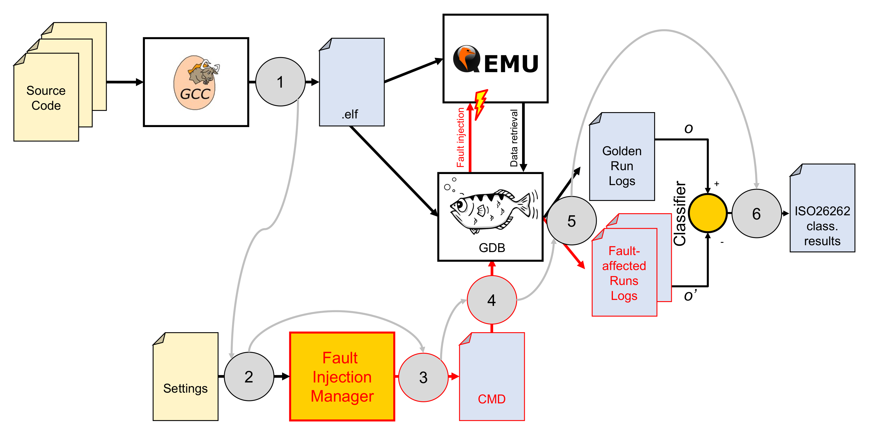
3.2. The Test Bench

To perform the performance assessment, we propose the test bench described in the following.
The core of the system is the FIM (the controller of our proposal), designed for this purpose by the authors. It interacts with three open-source software platforms: GCC, GDB, and QEMU.
To implement the test bench, a C/C++ compiler is necessary. Our choice fell on GCC. It is used for two different purposes.
The first one is to perform the cross-compilation of the hardened source code for the architecture of the target microcontroller. The result of this compilation process is an .ELF file, containing both the machine-executable code and the memory map information.
Once the .ELF file has been obtained, QEMU (the emulator used to run the target loads the machine-executable code), whereas GBD (acting as the injector, load generator, and the log function of the monitor) loads the memory map information (including debug symbols).
Its second purpose is to compile the classifier (performing the function of the readout analysis of the monitor), of which the source code is generated by the FIM based on the configured watches and the models of the faults it has been chosen to inject.
GDB (The GNU project debugger) [20] is the missing piece to complete the puzzle, as it allows the FIM to interact with the emulation environment offered by QEMU and the software running within it. Thanks to these interactions, GDB enables the management of the emulation environment (mainly starting/stopping the execution and set breakpoints) to monitor the execution of the embedded software. Moreover, it enables the injection of faults into the program counter (PC), the register file, and the memory locations of the emulated system.
An overall description of the proposed test bench is shown in Figure 1.
The assessment process is as follows:
  • The software developers compile their source code for the target platform (in this case, an RISC-V RV32I microcontroller [21]) using one of the available toolchains, such as [22]. We chose to use RISC-V since it is an open-source ISA that is gaining interest for automotive and space applications [23].
  • A settings file is prepared, containing information on the campaign to be performed.
  • The FIM (controller) is launched. It reads the settings file to generate all the scripts (represented by the CMD file in the figure) needed to perform the injections. Alongside the scripts, it also prepares the classifier source code.
  • The scripts are launched. These, by controlling GDB, perform the golden run and then all the required injections. For the golden run and each one of the injections (injector), a log file with the output of the program is saved (the log task of the monitor).
  • The classifier is compiled and run, taking the golden run and each of the fault-affected logs as its input.
  • The classifier results (one for each injection) are merged into the ISO 26262 classification, as described in Section 3.3.

3.2.1. FIM Settings File

The FIM loads a settings file describing a fault injection campaign. Its structure is hierarchic, with a campaign on top and lists of watches and fault models as its leaves.

Campaign

A campaign is described by:
  • A list of watches. One of these, called the end watch, defines the termination condition that allows the simulation system to determine if the software component under test finished its task.
  • A list of faults to be injected.

Watches

A watch can be a variable defined in a high-level programming language or a memory location to be monitored via GDB.
The following parameters are needed to describe a watch:
  • Symbol: the name of the variable to be watched. This field can be left blank if we want to monitor a memory location.
  • Address: the address of the memory location to be watched. This field is ignored in case the symbol name has been defined.
  • Description: a textual description of the watch. This field can be helpful for automatic report generation but is not required to perform the injection, and is hence left blank.
  • DetectionWatch and DetectedCondition: if DetectionWatch is true, it means that the variable/memory address contains the results of a RHF detection mechanism. The DetectedCondition field contains the condition that represents whether or not the detection occurred in relation to the DetectionWatch variable.

Fault Representation

A fault representation is a way to implement, inside the tool, a fault model in the form of a semiformal description of the considered RHF effects at the instruction set level.
We call it a semiformal description since each type of fault corresponds to a GDB script that performs its injection.
The following parameters (required to represent, in a semiformal model, the what, when, and where aspects) describe each fault model:
  • Type: the fault model to be injected.
    At the moment, two kinds of faults are available: Permanent and PermanentStuckAt.
  • Target: the name of the target register.
  • bitPosMaks: a 64-bit mask, used to a perform bitwise-level configuration of the fault.
  • Fault tolerance time interval (FTTI): the maximum allowed assembly instructions that the emulator can execute from the injection time until the detection occurs. After this time elapses, an eventual detection is considered invalid and hence not considered in the diagnostic coverage computation.
  • Minimum injection time: the minimum time (measured as number of machine instructions) that must elapse from the start of the simulation to the moment when the fault is injected.
  • Maximum injection time: the maximum time (measured as number of machine instructions) that can elapse from the start of the simulation to the moment when the fault is injected.
  • Permanence time: the number of assembly instructions executed after the fault injection if the software unit under testing does not set the termination condition.
  • Number of injections: the number of faults with the previous parameters to be randomly generated and injected.
To set up a meaningful campaign, three watches and a fault are needed. These three watches are:
  • An end-watch to let the test bench know when the software unit ended its function: if it were not specified, the FIM would not know when to finish the golden run.
  • A watch configured as a detection one, to enable the classifier to determine whether or not the detection mechanism has been triggered.
  • A watch configured as a normal one to allow the classifier to check if the behavior of the payload algorithm is the same as the golden run or not.

3.2.2. Classifier

The classifier is the component in charge of analyzing the log files obtained from the fault injection campaign.
It takes as its inputs the golden run and the considered fault instance log files. It compares the results of the software component under testing with those obtained during the golden run to determine if the computation results changed due to the injected failures, providing classifications for each injection. Moreover, it monitors the detection watches and the termination one.
After the classifier reads all the logs, its results are accumulated to obtain a classification compliant with ISO 26262, focusing on the experimental determination of the diagnostic coverage of the hardening mechanism.
It has been designed as an FSM, of which the state transitions are shown in Figure 2. It has the following states:
  • Latent: before injection of the fault.
  • Latent after injection: fault injected and behavior identical w.r.t. the golden run.
  • Erratic behavior: behavior different w.r.t. the golden run.
  • Infinite loop: PC moves in an infinite loop that is not present in the original program flow, but created by the interaction between the source code and the defective PC register.
  • Stuck at some instruction: PC remains stuck pointing to a valid instruction.
  • (Detected) by SW hardening: detected by the software hardening mechanism.
  • (Detected) by HW (mechanism): PC pointing outside the FLASH/RAM addressing space.
  • As golden: detected and with an output identical to the golden run.
  • False positive: detection before a fault is injected.
  • Moreover, states Undefined and Error indicate internal errors of the classifier. These states are not indicated in Figure 2.
The transition from the state Latent after injection or any of those in the Dangerous/Residual group to a state on the Detected side is allowed only before the FTTI elapses.
In contrast, a transition from the state (detected) by software hardening to the state As golden is performed when one last line of the log file has been read, although only if the behavior of the software components remains the same as that of the golden run for the entire log file.

3.3. ISO 26262-Compliant Classification

To move from the classifier results, based on the behavior of the application, to one compliant to part 5 of the ISO 26262.
We focused only on the detection capabilities. Our assessment was based only on comparisons between the golden (fault-free) runs and the fault-affected ones, with the following descriptions:
  • Safe: if the detection mechanism is triggered, and the output is the same as the one obtained from the golden run (regardless of whether it is due to the type of fault or the algorithm by itself, or thanks to a software-based mitigation strategy). Of course, to apply such a hypothesis, it is required that the software component is developed in compliance with the prescriptions of ISO 26262 part 6.
  • Latent: if the detection is not triggered, but the output is the same as the one obtained from the golden run.
  • Dangerous: the set of failure modes for which the detection mechanism is not triggered and for which the output is different from the golden run; so, it also includes multiple-point perceived faults.
  • Residual: based on the frequency of latent after injection (false negatives) obtained during the fault injections for a given fault.
  • False positive: when the detection mechanism is triggered, but no fault has been yet injected. ISO 26262 does not describe this class (coherently, since it mandates avoiding the presence of systematic errors, a.k.a., defects in the embedded software), but it is useful since we want to use this performance assessment system to aid developers of software detection strategies.
Moreover, as is usually carried out in FMEDA analysis, we are injecting only one fault per simulation due to the exponential increase of the needed simulations.
Figure 3 summarizes the classification in the form of a confusion matrix.
Starting from the classifier FSM (see Figure 2), the classifications of each injection are mapped with the ISO 26262 as follows:
  • Safe detected: the percentage of the injections for a given fault that ended up with a classification of as golden.
  • Detected: the percentage of the injections for a given fault that ended up with a classification of detected by either the software or a hardware detection mechanism. We chose to name them Detected since the effectiveness of the mitigation strategy was not considered.
  • Latent: the percentage of the injections for a given fault that ended up with a classification of latent after injection.
  • Dangerous: the percentage of the injections for a given fault that ended up with the classifications stuck at some instruction, erratic behavior, or infinite loop.
    These injections are referred to as Residual if they correspond to the same fault with different parameters found for simulation outcomes classified as Latent, or Detected.
The sum of the percentages of Safe Detected and Detected outcomes represents an experimental value of the diagnostic coverage described by ISO 26262. In contrast, the dangerous percentage accumulates all the undetected (hence, single points of failure in the ISO 26262 terminology) or residual percentages of undetected runs for a given fault model.
In addition to these four classifications, as said before, we also considered the percentage of false positives.

4. Conclusions

This paper focused on a fault injection system designed to assess the detection mechanisms implemented by the embedded software, designed to recognize random hardware failures affecting digital components. Our approach can help software developers working on automotive applications where the trade-off between safety and cost requirements has led to pushes for the adoption of software-only strategies. Therefore, our test bench has been developed to comply with the ISO 26262 automotive functional safety standard, parts 5 and 11, by providing justifications to map the chosen fault models affecting the program counter with the failure modes described by the Standard.
To allow software developers to assess the diagnostic coverage of their application experimentally, we have introduced a novel test bench based on a fault injection manager integrated with the open-source software platforms GCC, GDB, and QEMU.
Using the classification from [3], already presented in Section 2.1, the proposed system has the following characteristics.
A good presentativeness, since we justified the chosen fault model considering the types and distribution of injected corruptions: based on our interpretation of the failure modes described by ISO 26262 (see the Section 3.1), and considering that the ones regarding the failure modes can be retrieved the safety manual of the digital component.
From the usability perspective, the proposed methodology demonstrates good portability since the system is based on QEMU and GDB. On the one hand, QEMU emulates many ISAs, whereas GDB can be used as an injector or monitor in each of these. Using debug ports, it is possible for injection into real hardware components. It does not require a modification of the embedded software, so it has a low intrusiveness and a good flexibility, as the FIM is an open-source product. Each fault model has a relative GDB script acting as its semiformal model, so to add further fault models is sufficient to define the correspondent fault classes and script templates.
Considering its efficiency, the number of experiments is lowered thanks to an analysis of the activation and propagation of injected faults/errors. Moreover, it allows one to achieve the good activation and propagation of the injected faults/errors, and considering the faults affecting the program counter, it is possible to define a mask (called the bitPosMask in the case of permanent fault models) to set which bits can be affected. For this purpose, injection affecting too significant bits would create jumps that would always lead the PC to point outside the text segment of the program, whereas, conversely, if the bits involved are too low, this leads to hardware protection interventions for non-aligned access.
This test bench, integrated with the chosen open-source software, manages all the assessment phases, from fault generation to fault injection and ISA emulation, up to the classification of simulation results.
The classifier analyzes the log files obtained from the fault injection campaign, allowing the determination of diagnostic coverage via the implemented hardening mechanism.
We carried out tests to assess a control flow checking benchmark, obtaining an average execution time of about 31.2 s per injection (comprising the time needed for logging and classification). This duration was obtained running 2000 injections inside a virtual machine on a host computer equipped with an Intel Core i7 4770K CPU, clocked at 3.5 GHz. The execution time between the golden and fault-affected runs was very similar since most activities were related to the logging of the software results.

Author Contributions

Conceptualization, J.S., M.V., and F.T.; methodology, J.S., M.V., and F.T.; software, J.S.; validation, M.V., and F.T.; resources, M.V.; data curation, J.S.; writing—original draft preparation, J.S.; writing—review and editing, J.S., M.V., and F.T.; visualization, J.S.; supervision, M.V.; project administration, M.V.; funding acquisition, M.V., and F.T. All authors have read and agreed to the published version of the manuscript.

Funding

This work has been partially supported by Huawei Pisa Research Center, Pisa, Italy.

Institutional Review Board Statement

Not applicable.

Informed Consent Statement

Not applicable.

Data Availability Statement

Not applicable.

Conflicts of Interest

The authors declare no conflict of interest.

Abbreviations

The following abbreviations are used in this manuscript:
COTSCommercial Off-The-Shelf
DCDiagnostic Coverage
E/EEletrical and Electronics
FIFault Injection
FIMFault Injection Manager
FMFailure Mode
FMEDAFailure Mode, Effects, and Diagnostic Analysis
FSCFunctional Safety Concept
FSMFinite State Machine
FTAFault Tree Analysis
FTTIFault Tolerance Time Interval
HSIHardware/Software Interfaces
IPIntellectual Property
ISAInstruction Set Architecture
ISOInternational Standard Organization
MBSDModel-Based Software Design
PCProgram Counter
PLDProgrammable Logic Device
RHFRandom Hardware Failure
RISCReduced Instruction Set Computing
RSCFCRelationship Signatures for Control Flow Checking
SEooCSafety Element out of Context
SETASoftware-only Error-detection Technique using Assertions
SGSafety Goal
SIEDSoftware implemented error detection
SIHFTSoftware Implemented Hardware Fault Tolerance
TSCTechnical Safety Concept
TSRTechnical Safety Requirements
WDWatchdog

References

  1. Avizienis, A.; Laprie, J.C.; Randell, B.; Landwehr, C. Basic concepts and taxonomy of dependable and secure computing. IEEE Trans. Dependable Secur. Comput. 2004, 1, 11–33. [Google Scholar] [CrossRef] [Green Version]
  2. Hsueh, M.C.; Tsai, T.K.; Iyer, R.K. Fault injection techniques and tools. Computer 1997, 30, 75–82. [Google Scholar] [CrossRef] [Green Version]
  3. Natella, R.; Cotroneo, D.; Madeira, H.S. Assessing dependability with software fault injection: A survey. ACM Comput. Surv. 2016, 48, 1–55. [Google Scholar] [CrossRef]
  4. Bernardi, P.; Bovi, C.; Cantoro, R.; De Luca, S.; Meregalli, R.; Piumatti, D.; Sansonetti, A. Software-based self-test techniques of computational modules in dual issue embedded processors. In Proceedings of the 2015 20th IEEE European Test Symposium (ETS), Cluj-Napoca, Romania, 25–29 May 2015; pp. 1–2. [Google Scholar]
  5. Piumatti, D.; Sanchez, E.; Bernardi, P.; Martorana, R.; Pernice, M.A. An efficient strategy for the development of software test libraries for an automotive microcontroller family. Microelectron. Reliab. 2020, 115, 113962. [Google Scholar] [CrossRef]
  6. Cantoro, R.; Firrincieli, A.; Piumatti, D.; Restifo, M.; Sánchez, E.; Reorda, M.S. About on-line functionally untestable fault identification in microprocessor cores for safety-critical applications. In Proceedings of the 2018 IEEE 19th Latin-American Test Symposium (LATS), Sao Paulo, Brazil, 12–14 March 2018; pp. 1–6. [Google Scholar]
  7. Ruospo, A.; Piumatti, D.; Floridia, A.; Sanchez, E. A Suitability Analysis of Software Based Testing Strategies for the On-line Testing of Artificial Neural Networks Applications in Embedded Devices. In Proceedings of the 2021 IEEE 27th International Symposium on On-Line Testing and Robust System Design (IOLTS), Torino, Italy, 28–30 June 2021; pp. 1–6. [Google Scholar]
  8. Das, A.K.; Mishra, D.K.; Yu, J.; Leung, C.K. Smart Self-Healing and Self-Sensing Cementitious Composites-Recent Developments, Challenges, and Prospects. Adv. Civ. Eng. Mater. 2019, 8, 554–578. [Google Scholar] [CrossRef]
  9. Piumatti, D.; Sini, J.; Borlo, S.; Sonza Reorda, M.; Bojoi, R.; Violante, M. Multilevel Simulation Methodology for FMECA Study Applied to a Complex Cyber-Physical System. Electronics 2020, 9, 1736. [Google Scholar] [CrossRef]
  10. de Aguiar Geissler, F.; Kastensmidt, F.L.; Souza, J.E.P. Soft error injection methodology based on QEMU software platform. In Proceedings of the 2014 15th Latin American Test Workshop—LATW, Fortaleza, Brazil, 12–15 March 2014; pp. 1–5. [Google Scholar] [CrossRef]
  11. Bellard, F. QEMU, a Fast and Portable Dynamic Translator. In Proceedings of the ATEC ’05 Proceedings of the Annual Conference on USENIX Annual Technical Conference, Anaheim, CA, USA, 10–15 April 2005. [Google Scholar]
  12. Amarnath, R.; Bhat, S.N.; Munk, P.; Thaden, E. A Fault Injection Approach to Evaluate Soft-Error Dependability of System Calls. In Proceedings of the 2018 IEEE International Symposium on Software Reliability Engineering Workshops (ISSREW), Memphis, TN, USA, 15–18 October 2018; pp. 71–76. [Google Scholar]
  13. Schirmeier, H.; Hoffmann, M.; Dietrich, C.; Lenz, M.; Lohmann, D.; Spinczyk, O. FAIL*: An Open and Versatile Fault-Injection Framework for the Assessment of Software-Implemented Hardware Fault Tolerance. In Proceedings of the 2015 11th European Dependable Computing Conference (EDCC), Paris, France, 7–11 September 2015; pp. 245–255. [Google Scholar]
  14. Esposito, S.; Sini, J.; Violante, M. Real-Time Validation of Fault-Tolerant Mixed-Criticality Systems. In Proceedings of the 2018 IEEE 24th International Symposium on On-Line Testing And Robust System Design (IOLTS), Costa Brava, Spain, 2–4 July 2018; pp. 245–246. [Google Scholar]
  15. ISO 26262:2018 Road Vehicles—Functional Safety. 2018. Available online: https://www.iso.org/standard/68383.html (accessed on 23 November 2021).
  16. Sini, J.; Violante, M. A simulation-based methodology for aiding advanced driver assistance systems hazard analysis and risk assessment. Microelectron. Reliab. 2020, 109, 113661. [Google Scholar] [CrossRef]
  17. Sini, J.; Violante, M. An Automatic Approach to Perform FMEDA Safety Assessment on Hardware Designs. In Proceedings of the 2018 IEEE 24th International Symposium on On-Line Testing and Robust System Design (IOLTS), Costa Brava, Spain, 2–4 July 2018; pp. 49–52. [Google Scholar]
  18. Autonomous Car: A New Driver for Resilient Computing and Design-for-Test Online. Available online: https://nepp.nasa.gov/workshops/etw2016/talks/15WED/20160615-0930-Autonomous_Saxena-Nirmal-Saxena-Rec2016Jun16-nasaNEPP.pdf (accessed on 9 December 2021).
  19. Ries, G.L.; Choi, G.S.; Iyer, R.K. Device-level transient fault modeling. In Proceedings of the IEEE 24th International Symposium on Fault- Tolerant Computing, Austin, TX, USA, 15–17 June 1994; pp. 86–94. [Google Scholar] [CrossRef]
  20. The GNU Debugger. Available online: https://www.gnu.org/software/gdb/ (accessed on 23 November 2021).
  21. The RISC-V Instruction Set Manual Volume I: Unprivileged ISA Document Version 20191213. Available online: https://riscv.org/wp-content/uploads/2019/12/riscv-spec-20191213.pdf (accessed on 23 November 2021).
  22. GNU RISC-V Toolchain. Available online: https://github.com/johnwinans/riscv-toolchain-install-guide (accessed on 30 October 2021).
  23. Mascio, S.D.; Menicucci, A.; Furano, G.; Monteleone, C.; Ottavi, M. The case for RISC-V in space. In Applications in Electronics Pervading the Industry, Environment, and Society; Saponara, S., De Gloria, A., Eds.; Springer International Publishing: Cham, Switzerland, 2018; pp. 319–325. [Google Scholar]
Figure 1. The proposed test bench architecture. GCC also compiles the classifier, of which the source code is generated by the FIM. The round numbered boxes and the gray arrows represent the functional flow of the system.
Electronics 11 00901 g001
Figure 2. The classifier FSM.
Electronics 11 00901 g002
Figure 3. The confusion matrix of the proposed classification, compliant with ISO 26262.
Electronics 11 00901 g003
Publisher’s Note: MDPI stays neutral with regard to jurisdictional claims in published maps and institutional affiliations.

