2. State of the Art
In this section we will first present a brief summary of the different possibilities to deploy a LoRaWAN network. Other aspects such as platforms for IoT, more focused on data storage, distribution, processing and visualization (such as Google Cloud Platform, IBM Watson IoT, Amazon AWS IoT Core, Microsoft Azure, among others) are outside the scope of this work.
An example of a large LoRaWAN network architecture is The Things Networks (TTN), an open, collaborative network with more than 20,000 gateways around the world. Its architecture [
4] is made up of bridges that interact with gateways, connected to routers that route to the corresponding brokers (depending on the geographical location). These interact with network servers and handlers that manage communication with application servers. There is no detailed information about the real elements composing the architecture or their organization.
Regarding LoRaWAN platforms, it is worth highlighting Chirpstack [
5], a free and open source platform that allows to deploy private networks, and LORIOT [
6], free for small networks (up to 30 nodes) but without the possibility of setting up private networks. Chirpstack provides the different entities (LoRaWAN network and application servers, and a Gateway Bridge) so it is up to the developer which network topology to use or other deployment details. LORIOT includes 13 free community network servers, a professional LoRaWAN network server with a 99.9% SLA, built-in redundancy and new accessible features to manage and scale a secure LoRaWAN network, and a carrier-grade private LoRaWAN network server solution for production services at any scale. Apart from this, no further details about their architecture are given.
It shall be noticed that, since the Chirpstack platform freely provides all the entities required to deploy a private network, we will use Chirpstack for our deployment.
Additionally, since this work will enhance MQTT in our platform, we also include here some relevant works found in the literature that optimize the MQTT protocol for IoT deployments.
One of the most relevant modifications of the MQTT protocol for IoT is MQTT-SN (MQTT for Sensor Networks) [
7]. MQTT-SN is designed for wireless networks, with low power battery operated sensors with very limited processing power and storage, with a limited payload size and not always connected (i.e., sleeping). With this objective in mind, it uses UDP as transport protocol and topic identifiers instead of topic names. The architecture also changes with respect to MQTT, with MQTT-SN clients, gateways and forwarders. The gateways act as MQTT-SN brokers and also translate to MQTT to forward messages to MQTT brokers (aggregating clients or not). The forwarders just retransmit MQTT-SN packets from clients to gateways. MQTT-SN utilizes multicast for discovery, but data is sent using unicast. The main differences with our solution is that nodes do not use standard MQTT and that messages are not multicasted.
Another work, MQTT-ST (MQTT Spanning Tree), focuses on the communication between distributed MQTT brokers. Its main objective is to avoid potentially harmful message loops between brokers. After an initial phase, at runtime, the MQTT-SN brokers work exactly as MQTT brokers. Although this optimization may be very useful, it does not contemplate multicasting or any other feature to reduce latency or traffic generation.
Direct Multicast-MQTT (DM-MQTT) [
8] follows a similar approach to our solution, since it multicasts MQTT messages within an SDN network. However, for QoS (Quality of Service) level 0, multicast is performed directly between publishers and subscribers without brokers. This may create scalability issues in the SDN controller if we have a large number of MQTT clients. In addition, they use a CBT (core-based tree) with a rendezvous point, which may not be optimal from a delay point of view. Although a CBT is more scalable than an SBT (source-based tree, which uses the shortest paths), our proposal aggregates a large number of MQTT clients in a few number of MQTT proxies, so using a source-based tree does not represent a scalability problem and additionally optimizes delay. Furthermore, the authors do not explain how a TCP-based protocol such as MQTT can be sent using multicast. In our work, MQTT proxies forward MQTT messages over UDP, which allows multicasting. The mapping between MQTT topics and multicast IP addresses is done thanks to a new MQTT2MULTICAST protocol. We also propose an aggregation scheme for MQTT topics used by LoRaWAN in order to reduce the number of multicast groups. Another difference is that DM-MQTT requires a hierarchical structure for the MQTT brokers, with one master broker located on the SDN controller (although logically separated). In our solution, all MQTT proxies are equal which also reduces the possibility of bottlenecks.
Finally, MQTT multicast [
9] is used to allow a single publisher to reach a broad audience of subscribers without the intervention of an MQTT broker. This software is intended for GNUnet [
10], a free software for decentrilized P2P (Peer-to-Peer) networks. In MQTT multicast, a publisher creates a GNUnet-MULTICAST channel for each topic to start a group. The main differences with our solution is that (1) it requires a P2P network, (2) the multicasting is done by the publishers, i.e., messages and topics are not aggregated by brokers or proxies, and (3) it is not compatible with already existing MQTT clients.
3. Technical Overview of LoRaWAN
LoRaWAN is an open standard which specifies the network architecture and the communication protocol to connect between each entity of the network. The design of the network architecture and the relates protocols are determined by the network capacity, the battery lifetime of the nodes, the security, and the applications that can run over the network [
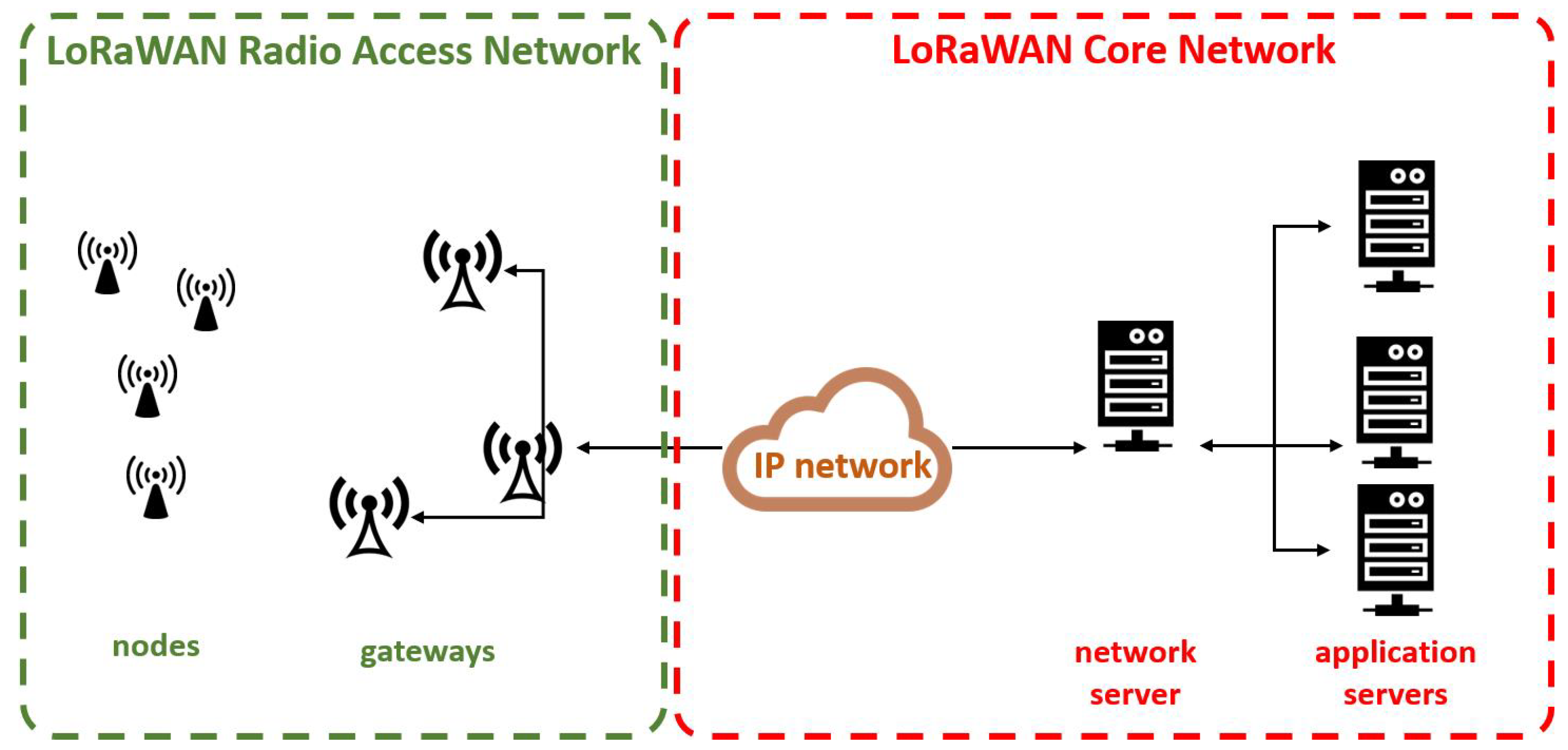
11]. To illustrate a typical LoRaWAN network,
Figure 1 shows a star-of-stars topology where one or more gateways (concentrators) relay download and upload traffic among end-nodes (mobile or fixed in a location) and a central network server respectively. The network server steers the traffic between each end-device and the associated application server. The communications are bi-directional. Communications between gateways and end-devices are a single-hop LoRa (the physical layer of a LoRaWAN network) or FSK (Frequency Shift Keying) connections. Communcations between gateways and the network servers use standard IP.
LoRa is a chirp spread spectrum based modulation developed by Cycleo in 2009 and acquired by Semtech in 2012. LoRa modulation complexity is low thanks to the equivalent offsets in timing and frequency between the transmitter and the receiver. The data signal is modulated onto a chirp signal that changes its frequency with time. The chirp rate defines the spectral bandwidth (BW) of a LoRa signal. For instance, a spectral BW of 125 kHz corresponds to a chip rate of 125,000 chips/sec. The data rate can change depending on the employed spreading factor (
SF), if we assume a fixed BW. The number of raw bits carried per symbol is expressed as
, and varies between 7 and 12. LoRa modulation includes a FEC (Forward Error Correction) scheme which adds redudancy in the code to find and correct erroneous bits. This improves the robustness of the transmitted signal [
12].
is the Code Rate and its values can vary between 1 and 4.
The data rate
is calculated as follows:
where
is the spreading factor, the second term corresponds to
or symbol rate (symbols/sec) and the third term depends on the coding rate (
). Thus, assuming fixed BW and coding rate, the data rate decreases as the
increases.
Table 1 presents a data rate (DR) configuration assuming a 125 kHz bandwidth and the default LoRaWAN Code Rate (4/5). The bit rate increases and the ToA (Time on Air) decreases as the
SF is decremented.
The communication between end-nodes and gateways uses different spreading factors and channels. In every transmission, the end-device selects the transmission channel in a pseudo-random way. The
SF (or DR) is selected considering the message duration and communication range by using an Adaptive Data Rate (ADR) scheme [
1]. In each transmission, the DR is selected considering the link budget (the higher the link budget, the faster DR or
SF selected). Parallel transmissions in the same channel but in different SFs will not collide due to the orthogonality of the SFs. This can be used to improve the network capacity.
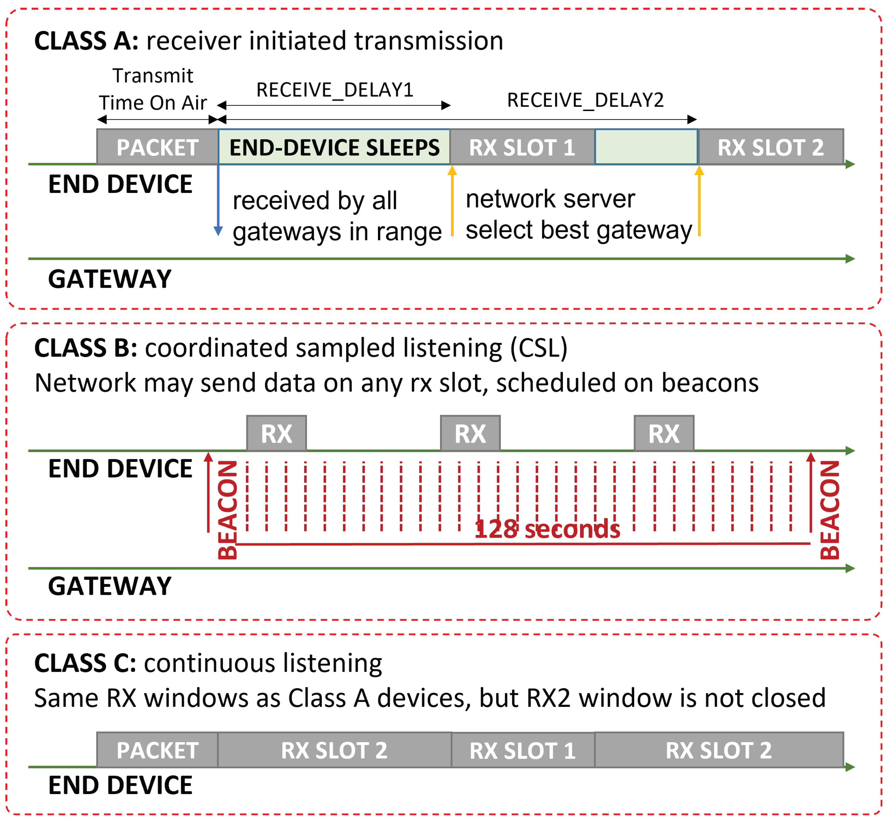
Three classes of LoRaWAN end-devices are considered in the LoRaWAN standard (classes A, B and C), depicted in
Figure 2. Class A is mandatory and the most employed, typical for battery-operated sensors. In Class A devices, two receiving windows are opened after an uplink transmission in order to receive a downlink transmission. Class B devices are typically battery-operated actuators. These devices behave similar, but use extra receive windows scheduled by beacon frames. Class C devices are typically mains powered. They are continuously listening except when transmitting.
Regarding frequency spectrum usage, LoRaWAN uses license-free sub-gigahertz radio frequency bands like 433 MHz, 868 MHz, and 915 MHz depending on the country. In Europe, LoRaWAN networks operates in the EU863-870 ISM band which allows up to eight channels with a 125 kHz bandwidth each, being three of them mandatory (868.1, 868.3, and 868.5 MHz). In order to respect the different regulations for these frequency bands, LoRaWAN devices are limited to a duty-cycle, being 1% in Europe due to ETSI (European Telecommunications Standards Institute) regulations.
6. Proof of Concept
As proof of concept, an SDN network has been implemented using Mininet [
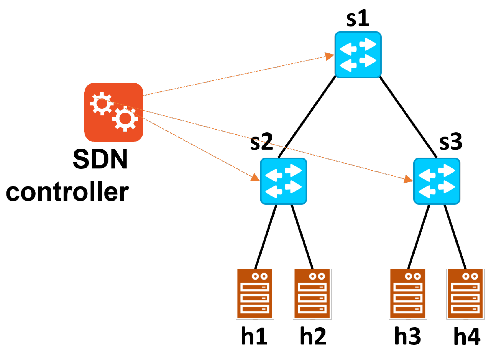
15] which will create a tree topology with the required number of levels with their corresponding fanouts. For initial testing, we employed a tree topology with 3 switches, i.e., a root switch (s1) and two leaf switches (s2 and s3), which connect 4 edge nodes (h1 and h2 connected to s2, and h3 and h4 connected to s3), see
Figure 8.
Nodes h1 and h4 run MQTT proxies that have been programmed using Scapy [
16]. Our implementation supports MQTT QoS 0, although it can be easily extended to support QoS levels 1 and 2. One of the nodes (tipically h1) uses a real network interface of the PC it is running on, allowing it to connect directly to the LoRaWAN backbone. In this case, for simplicity, we choose to use containers, orchestrated using Kubernetes [
17], which execute the different entities of the Chirpstack platform (gateway bridge, network and application servers) in the LoRaWAN gateway itself, as done in [
18]. This gateway is a Pygate from Pycom [
19]. FiPy [
20] nodes are available with PySense expansion boards, in addition to other LoRaWAN nodes such as TTGO T-Hygrow [
21] with its LoRa extension module. RYU [
22] has been selected as the SDN controller, which supports OpenFlow v1.3 [
23]. We implement the MQTT2MULTICAST server and the multicast routing algorithm (based on the shortest path) on top of RYU. The data sent by MQTT are stored in an InfluxDB database [
24] by a Python script. These data are finally visualized using Grafana [
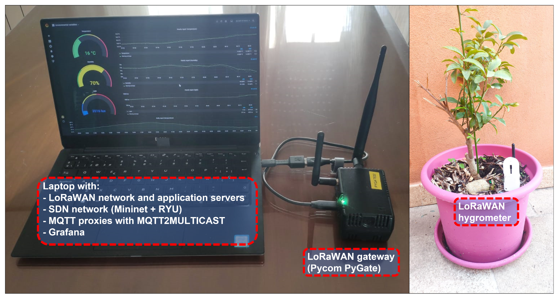
25].
Figure 9 shows our prototype.
As a demonstration of its operation,
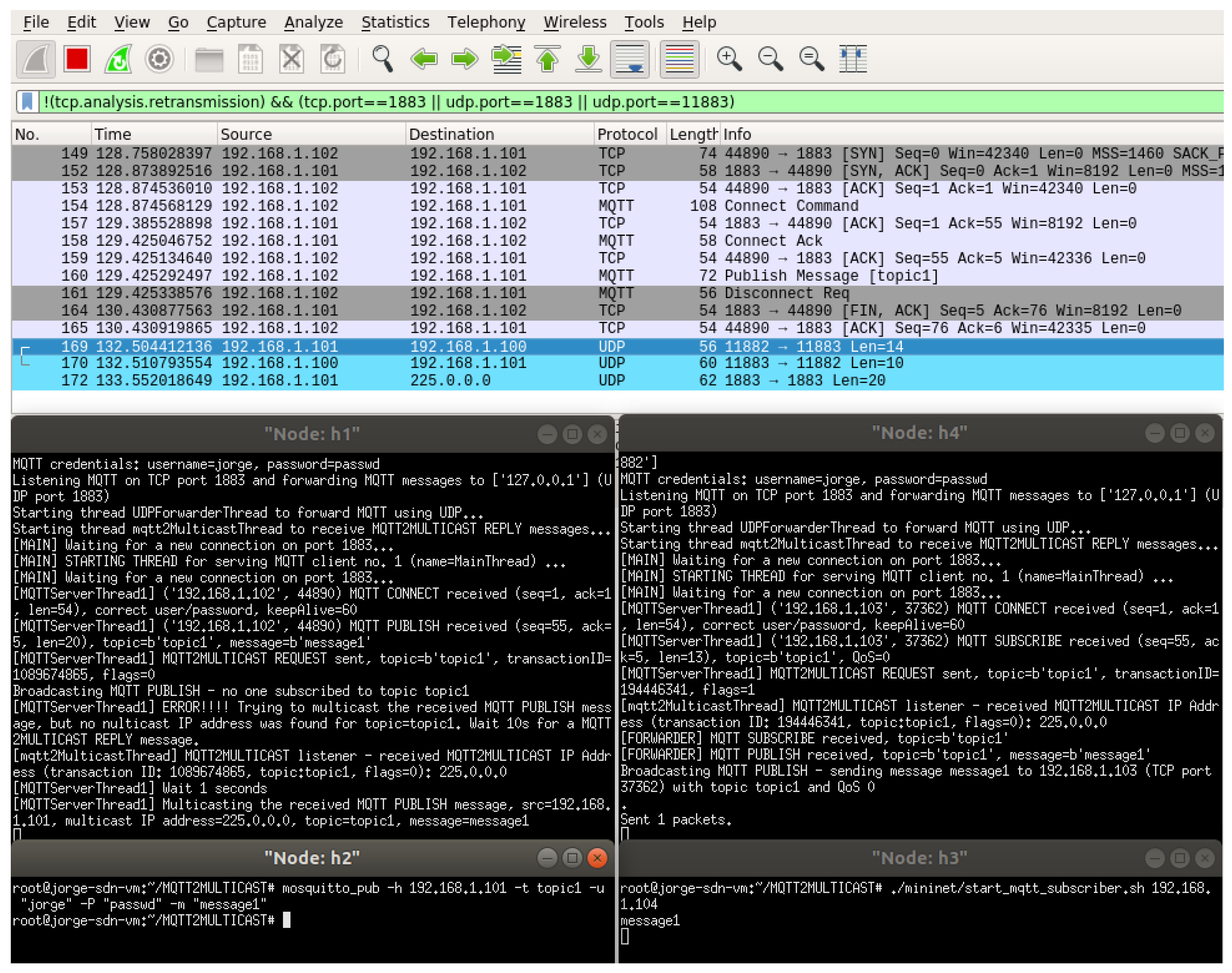
Figure 10 shows the traces of all the devices when h2 connects to h1 as a subscriber (using the
mosquitto_sub command) and h4 sends a message “message1” as publisher to the topic “topic1” (using the
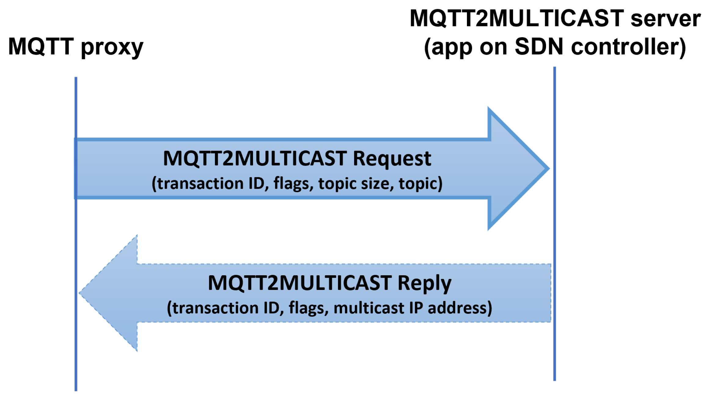
mosquitto_pub command). As shown in the Wireshark trace, taken at h1, h1 responds to h2’s subscription request behaving as a broker would, with the MQTT messages Connect, ConnAck, Subscribe and SubAck. Additionally, h1 asks to the MQTT2MULTICAST server (implemented in the SDN controller, with IP address 192.168.1.100) for a multicast IP address associated to the topic using an MQTT2MULTICAST Request (UDP port 11,883 in Wireshark). In response, h1 receives an MQTT2MULTICAST Reply assigning the multicast IP address 225.0.0.0. Finally, we can observe the last UDP packet at port 1883 sent to the address 225.0.0.0, which is the MQTT Publish message being forwarded using multicast, in this example, to the MQTT proxy at h4. Finally, h4 forwards the MQTT Publish message to h3, which receives it correctly, as shown in the corresponding console.
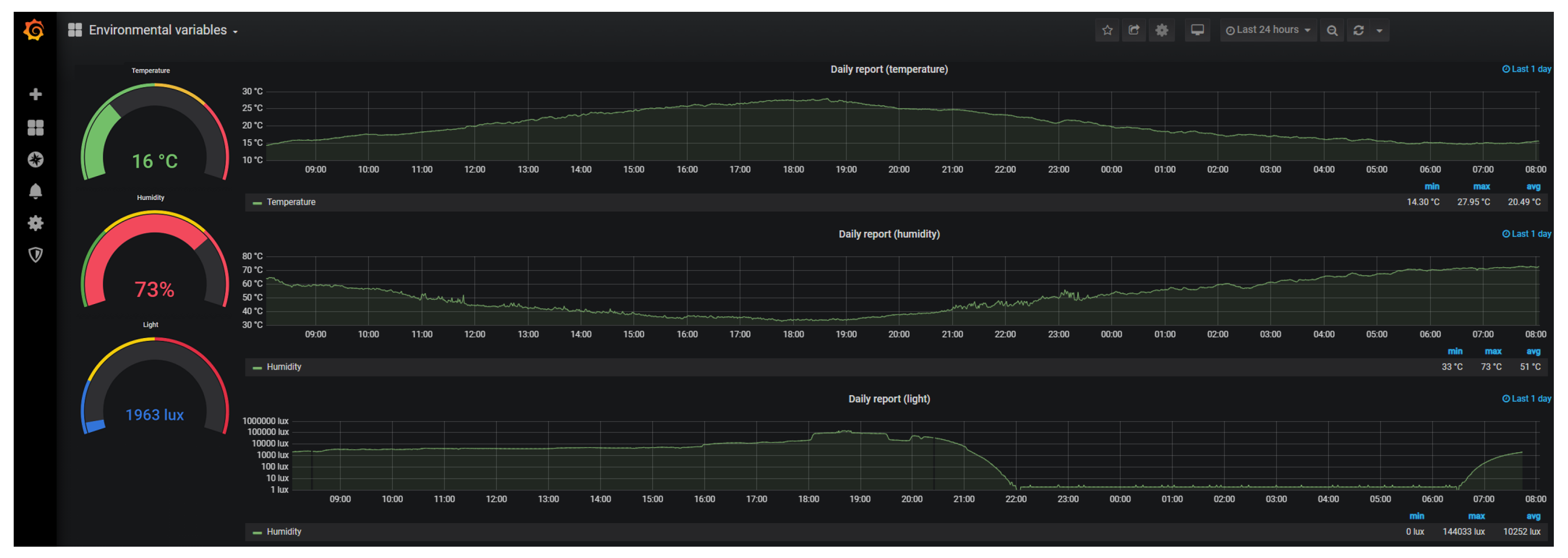
Figure 11 shows part of the data displayed in Grafana in our prototype. In this example, a LoRaWAN device with several sensors measures temperature, humidity and light. The device sends the data via LoRaWAN to a gateway, which is connected to the corresponding LoRaWAN network and application servers. The application server is connected to one of our MQTT proxies, which sends the information over MQTT to other proxies but also to our Grafana platform. As it can be seen, as an example, instantaneous temperature, humidity and light values and graphs with the values of the last day are shown. In the implemented dashboards, graphs of the last hour and with the minimum, average and maximum values of these metrics are also displayed for the last day per hour, and for the last week and last month per day.
7. Results
We have conducted three experiments to evaluate the performance of our solution. In particular, we compare (1) the delay between one data publication and its reception by a subscriber using MQTT and MQTT over multicast, (2) the amount of traffic in the SDN network also for both MQTT and MQTT over multicast, and (3) the amount of signaling traffic for a typical multicast routing protocol (PIM-SSM, Protocol Independent Multicast—Source Specific Mode) and MQTT2MULTICAST.
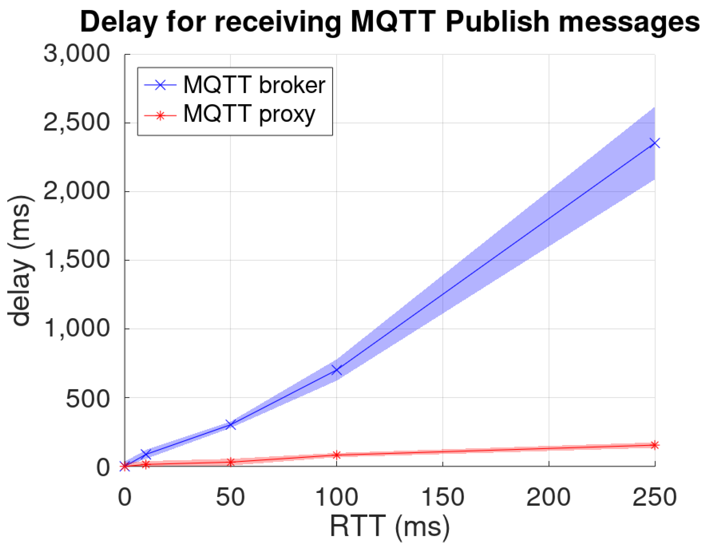
First we tested the MQTT latency reduction due to the usage of MQTT over UDP/ multicast in the SDN network instead of MQTT over TCP. Using MQTT over TCP, a publication requires 12 messages (TCP connection establishment, Connect/ConnAck, Publish, Disconnect, connection termination, and TCP ACKs). Using our solution, only the Publish message would traverse the SDN network. This reduction in messages implies a lower latency (from data publication until reception), being a more noticeable effect for high RTT values, as shown in
Figure 12. In order to achieve a fair comparison, in this experiment the broker is a modification of our proxy implemented with Python/Scapy. For this experiment, we capture packet traces using
tshark [
26] at the publisher and the subscribers, so we can obtain the time between the publication and its reception by post-processing these traces. On average, the latency is reduced by approx. 90% (between 84% for RTT = 10 ms and 95% for RTT = 250 ms).
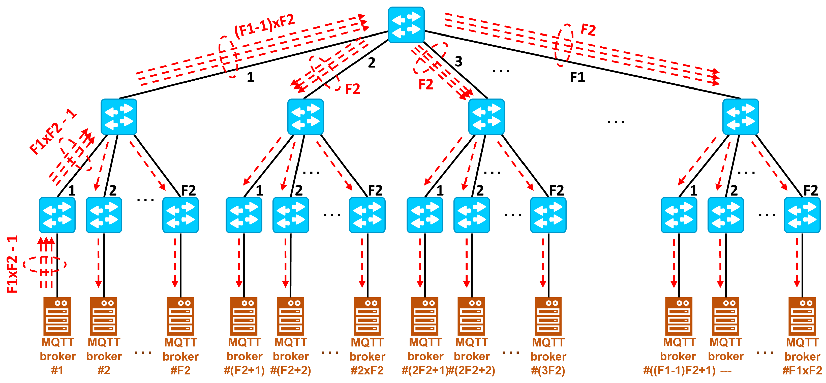
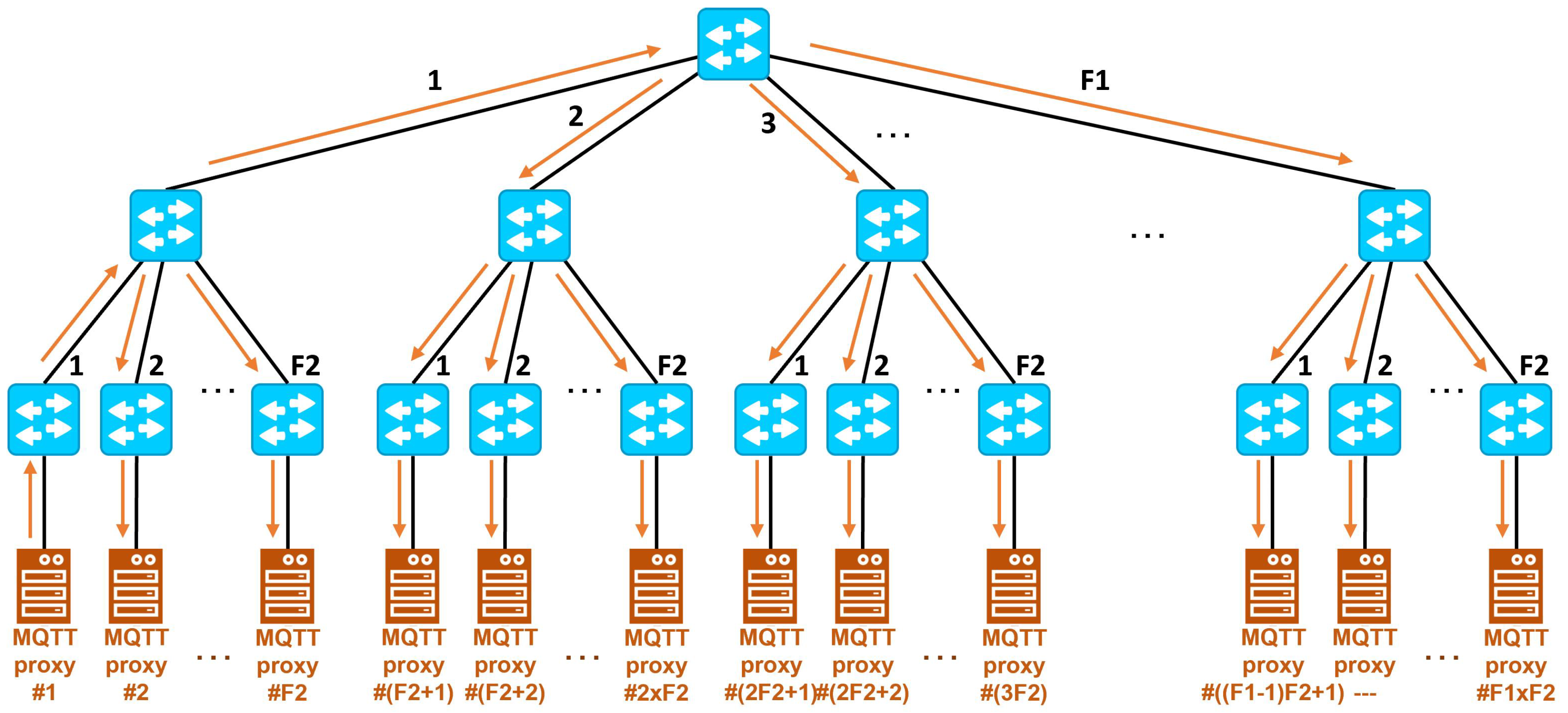
Next, we describe the reduction of packets transmitted over the SDN network when using multicast instead of unicast for the proposed tree topology. In the case of unicast, e.g., when using normal MQTT brokers which transmit over TCP, the number of packets is depicted in
Figure 13. We assume that one of the brokers connected to a leaf switch will be sending one packet (e.g., an MQTT Publish message) to the brokers connected to the remaining leaf switches, i.e., a total of
, where
is the fanout in the last level and
is the fanout in the first level (
is the number of leaf switches). Its corresponding leaf switch will forward these messages to its parent switch. The parent of that leaf switch will receive the packets and will (1) send one packet to its remaining
child switches and (2) forward
messages for the rest of the leaf switches, messages which are sent to the root switch. The root switch will forward these messages to its child switches, except to the parent of the source leaf switch. The number of messages in this case is
to each switch, i.e., a total of
messages, matching the number of packets received by the root switch. Each of the switches in the first level (except the switch corresponding to the source) will then forward one message to each leaf switch, i.e., a total of
messages. Finally, each of these
leaf switches will forward one message to their corresponding brokers, i.e.,
messages. All these messages total
. If we consider the TCP ACK messages in the opposite direction, the number of packets would double.
In the case of multicast, e.g., when using our MQTT proxies which transmit using multicast over UDP, the number of messages is depicted in
Figure 14. In this case, the source will send only one message, which is forwarded by its leaf switch to its parent switch. This switch will forward one message to the remaining child switches, i.e.,
, which are in turn forwarded to their respective proxies, and one message to the root tree. The root tree will forward the message to the remaining
switches in the first level, which will then transmit the message to their respective
leaf switches. These leaf switches will also forward the message to their respective proxies. All these messages total
. There are no ACKs in this scheme.
As an illustrative example, let us consider some numbers from The Things Network [
4]. Currently, TTN is composed of 20.6K LoRaWAN gateways in 547 communities (coinciding with cities) across 151 countries, with a total of 44.3M messages/day. This means that, on average, 1 message is sent every 40.2 s per gateway. The top 5 largest communities own between 218 and 167 gateways. Thus, we can assume that a large city could deploy around 200 gateways.
Let us further consider that the LoRaWAN servers and the MQTT proxies are deployed as containers in the edge nodes. For load balancing and redundancy purposes, we should deploy at least two LoRaWAN servers (with their corresponding MQTT proxies) per city, i.e., one every 100 gateways. In the case of a large region such as Andalusia, with 8 provinces, we could employ an SDN network with a tree topology with fanouts and .
With these numbers, one MQTT message (e.g., when a node sends one LoRaWAN frame) will generate 89 messages () within the SDN network (plus their corresponding TCP ACKs) if normal MQTT brokers are employed. If we employ our MQTT proxies with MQTT2MULTICAST, only 40 messages () are required (without TCP ACKs).
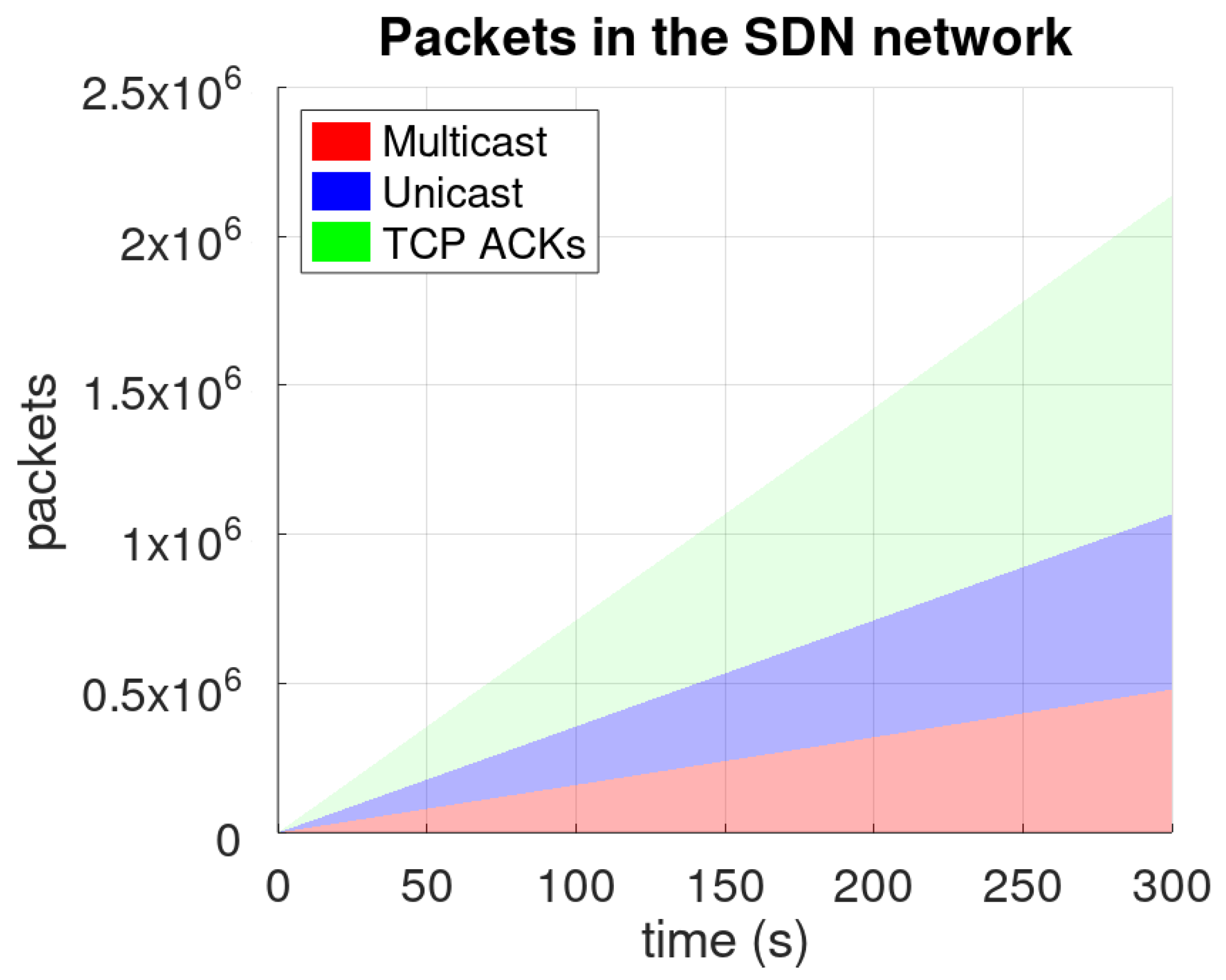
Since we are considering in this example 8 cities with 200 gateways per city, assuming 1 message every 40 s (as in TTN),
Figure 15 shows the evolution of the number of packets within the SDN network. The reduction in the number of packets is 55% if we only consider data packets, and 77.5% if we also take into account TCP ACKs.
We also tested the reduction of signalling traffic comparing our MQTT2MULTICAST scheme to PIM-SSM, a typical source-based multicast routing protocol. Using PIM-SSM, the nodes and the edge routers require to also send IGMP packets to join multicast groups. This is not required using MQTT2MULTICAST, because MQTT2MULTICAST already supports the mapping between publishers, subscribers, their topics, and their corresponding multicast addresses. In this experiment, we again used tshark in all the routers/switches and obtained the number of packets for each protocol by using the appropriate packet filters.
Since MQTT proxies aggregate many subscribers, we assume that most likely there is at least one subscriber for a specific topic (a specific ApplicationID in our LoRaWAN network, which aggregates several MQTT topics, as discussed in
Section 4). This means that, using MQTT2MULTICAST, only the initial MQTT2MULTICAST requests and replies are required. Assuming the previous scenario (
) and one topic (i.e., one ApplicationID mapped to one multicast IP address), the number of messages is very low (only 32 packets). However, the number of messages for joining/maintaining IGMP groups and the PIM-SSM messages to create the multicast routing trees are much higher. We create specific experiments using our network prototype (based on Mininet and RYU) with both solutions (PIM-SSM and MQTT2MULTICAST).
Figure 16 compares both situations, being near 15,000 messages after 5 min in the second case. Thus, our solution highly decreases the required signaling for multicast routing.
Finally, we have also tested the scalability of using multicast in our architecture. Since the number of switches in the Mininet is limited by the computational cost of their emulation, we have chosen to calculate the time to generate the multicast routes using graphs instead. For this, the NetworkX [
27] library has been used, following the same approach implemented in our testbed.
The tree topology consists of a root node and two levels, similar to those in
Figure 13 and
Figure 14. For simplicity, we assume that the fanouts of each level are equal. We also assume the worst case scenario, in which all leaf nodes subscribe to all other nodes. Multicast trees have been calculated using a virtual machine with 1 core and 8 GB of RAM in VirtualBox. Ten repetitions have been performed for each number of edge nodes in order to improve the reliability of the results.
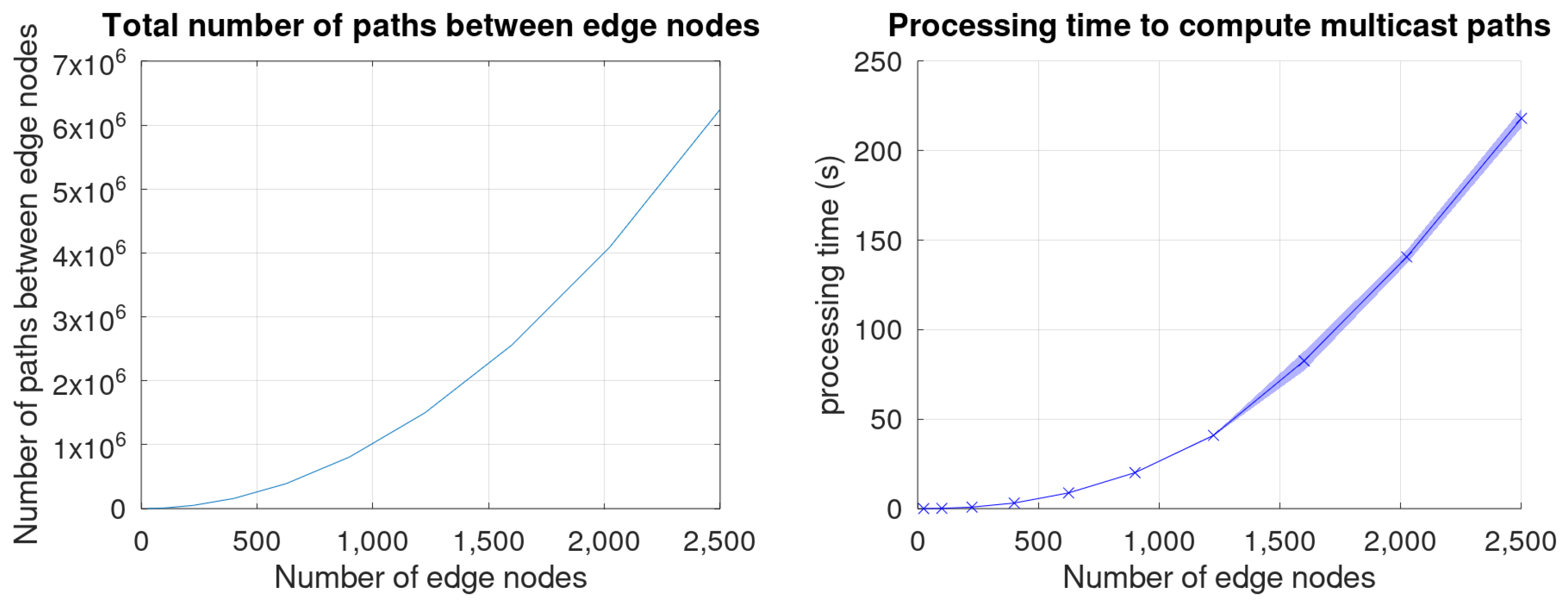
Figure 17 shows the time required to compute all the possible paths between edge nodes.
As shown, the total number of possible paths increases exponentially with the number of edge nodes. The behaviour is also similar for the time to compute those paths. This time is lower than four minutes for up to 2500 nodes, being lower than 30 s for 1000 nodes. These values are tolerable for large networks, especially considering that (1) this is the worst case scenario (all possible paths are created), (2) the executing machine may have better performance than the one used in our experiments (e.g., more CPU cores, possibly using parallel execution of the shortest path algorithm), (3) the shortest path algorithm may be optimized for our tree topology and (4) in a real network, all the paths are not required to be computed simultaneously but progressively, based on publishers and subscribers’ behaviour. These calculations are performed by an application at the SDN controller. Thus, the SDN controller will be able to accommodate large networks (up to a few thousands of edge nodes) without scalability problems.
Finally, since each edge node can manage tens of LoRaWAN gateways, our architecture will be able to support tens of thousands of them.
8. Conclusions
In this article, we present the design of an IoT network architecture oriented to the collection, processing and visualization of environmental variables. This network is composed of a radio access network and a core network. The RAN is based on LoRaWAN due to its characteristics of low power consumption, high converage, easy scalability and license free operation, which makes it adequate for massive IoT communications. The core network is based on Software Defined Networking, which provides great flexibility and easy of development. This SDN network provides connectivity between the LoRaWAN networks and other entities required for data distribution, processing and visualization. Most of these functionalities are expected to be deployed in remote clouds or edge resources.
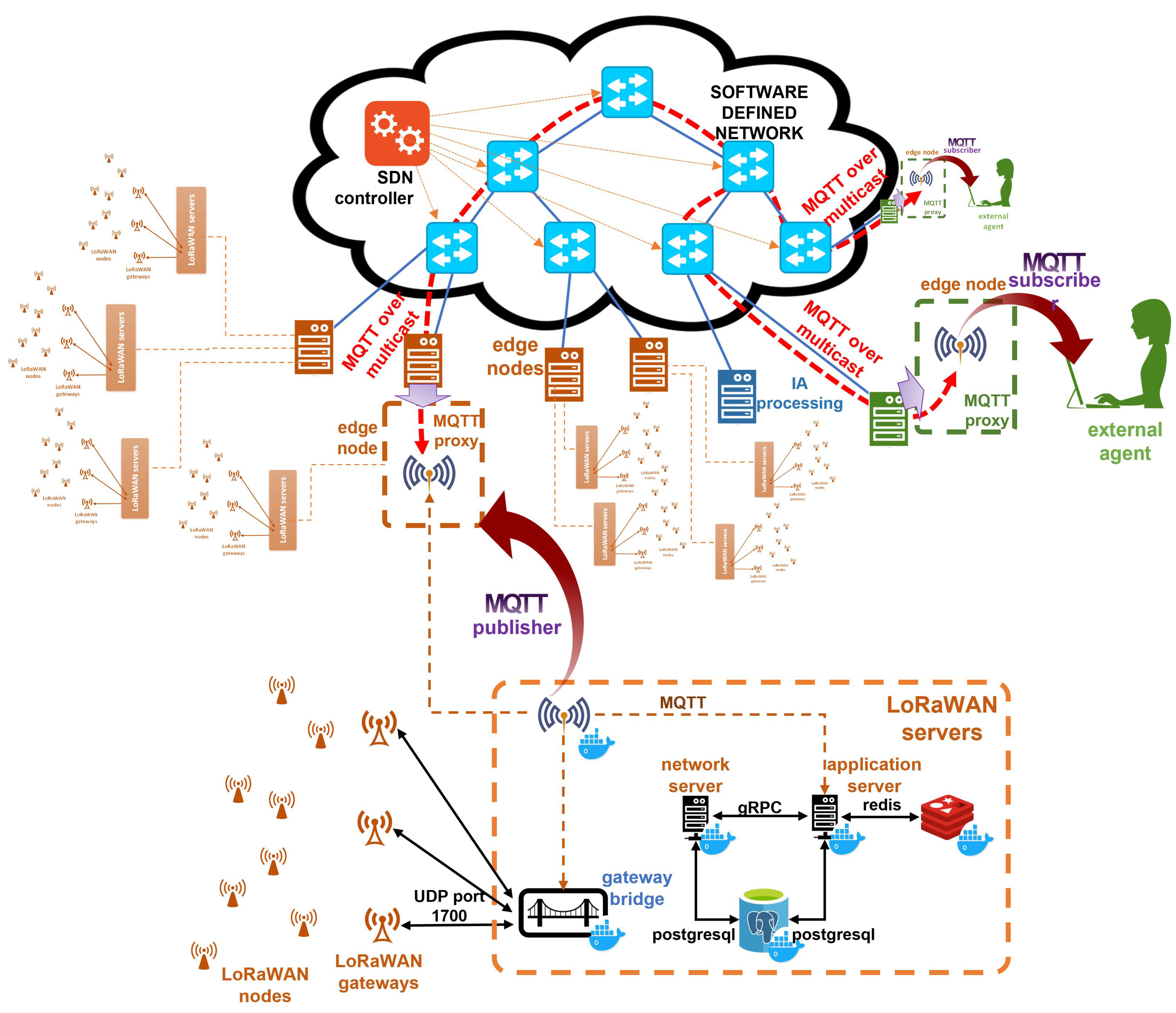
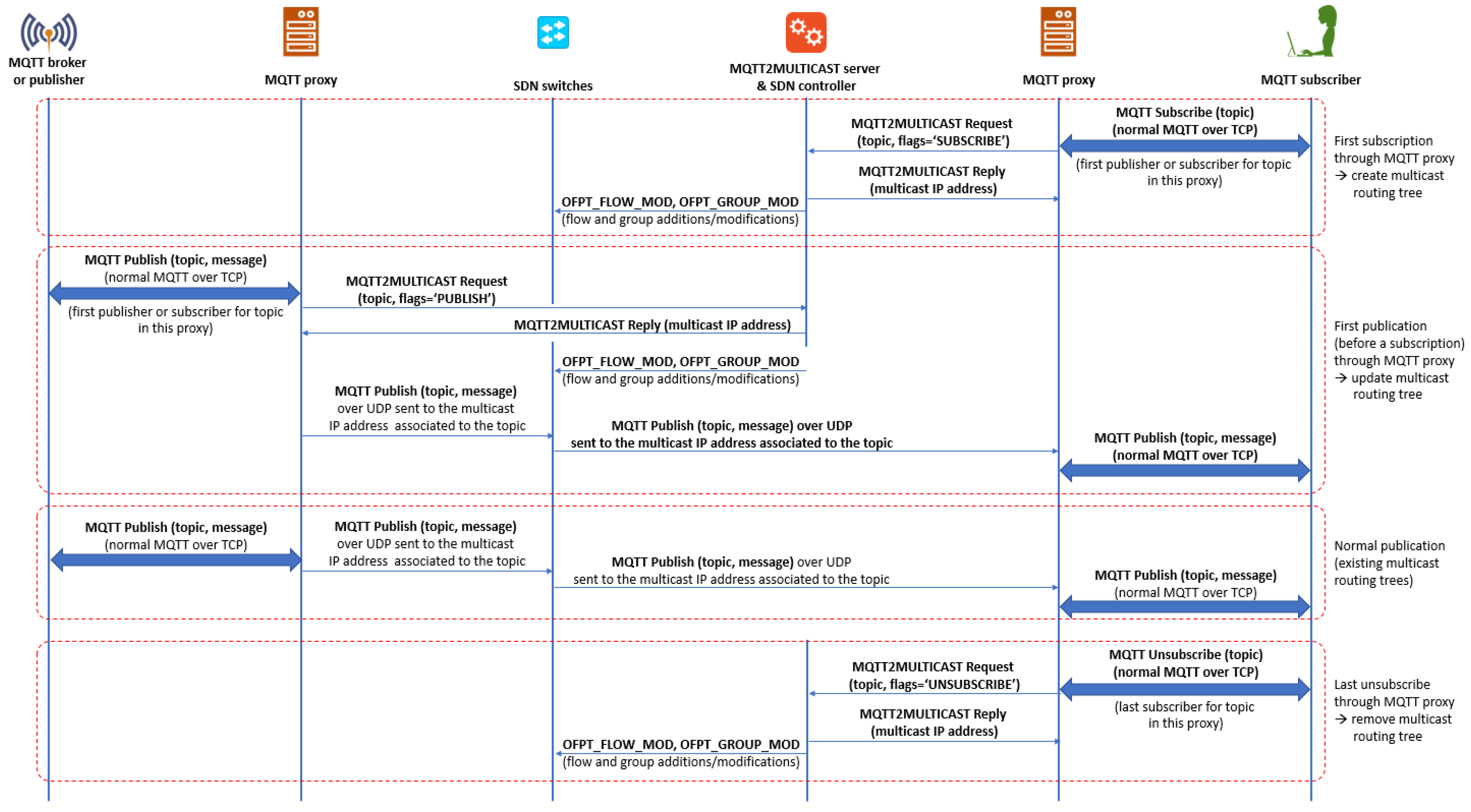
One of the most relevant protocols for data distribution in IoT applications is MQTT, which is based on the publish/subscribe paradigm. Leveraging SDN for enhancing MQTT, we propose MQTT2MULTICAST. Our solution employs MQTT brokers at the edge nodes, which act as MQTT brokers to local clients and multicast MQTT publications (using UDP instead of TCP) to other proxies that have subscribers for the specific topic. For that purpose, MQTT proxies utilize the MQTT2MULTICAST protocol to ask a server for a mapping between MQTT topics and their corresponding multicast IP addresses. The MQTT2MULTICAST server is implemented as an SDN controller application, which creates the required multicast routing trees within the SDN. These multicast routing trees are source-based, so the shortest paths between the publishers and the proxies are created by enforcing flow and group entries in the required SDN switches. Once the routing trees are created, the MQTT proxies can start multicasting the Publish messages.
We implemented this network architecture using Mininet for the SDN network, RYU as the SDN controller, and implementing (1) the MQTT proxies in Python with the Scapy library, (2) the MQTT2MULTICAST server as a RYU application, and (3) source-based multicast routing also as part of the RYU application. We tested its proper behaviour using real applications (
mosquitto_sub and
mosquitto_pub) and also by implementing a proof of concept with real equipment, i.e., a LoRaWAN network with nodes, gateways, LoRaWAN servers (using the Chirpstack platform) and data visualization (using InfluxDB and Grafana). We released our testbed environment as an open-source project [
3], allowing for reproducible research.
Finally, we conducted experiments to assess the performance of our prototype. We improved the publication delay approx. by 90% by eliminating non-required signaling and their corresponding round-trip times. In the scenario under evaluation (a tree topology with 16 edge nodes), we reduced the number of packets within the SDN network by 55% (or 77.5% if we consider TCP ACKs) and we almost eliminated the signaling related to multicast routing (compared to other multicast routing protocols such as PIM-SSM). Moreover, we conducted experiments to analyze the scalability of our proposal, showing that the architecture is able to accommodate tens of thousands of LoRaWAN gateways.


 ,
, 


