Article

3D Void Handling Geographic P2P-RPL for Indoor Multi-Hop IR-UWB Networks

Department of Electrical and Electronics Engineering, Konkuk University, Seoul 05029, Korea
*
Author to whom correspondence should be addressed.
Electronics 2022, 11(4), 625; https://doi.org/10.3390/electronics11040625
Submission received: 30 December 2021 / Revised: 10 February 2022 / Accepted: 15 February 2022 / Published: 17 February 2022
(This article belongs to the Special Issue IoT Sensor Network Application)

Abstract

:
IETF has standardized the point-to-point RPL (P2P-RPL) to ensure reliable and optimal P2P route discovery for low-power and lossy networks (LLNs). P2P-RPL propagates route discovery packets to all nodes in the network, which results in high routing communication overheads. Recently, other RPL-based P2P routing algorithms have been proposed to reduce such overheads, but still, quite an amount of overheads occur due to their flooding-based approach. In real life 3D environments, a larger number of nodes should be deployed to guarantee the full network connectivity, and thus the flooding strategy incurs higher overheads. In effort to alleviate high overheads, geographic routing is an attractive solution that exploits the nodes’ geographic locations in its next-hop routing selection. However, geographic routing inherently suffers from the local minimum (void) problem following greedy next-hop selection. Local minima occur more often in 3D space, and therefore, a reliable 3D void handling technique is required. In this paper, we propose greedy forwarding and void handling point-to-point RPL with adaptive trickle timer (GVA-P2P-RPL), which is a novel RPL-based P2P routing protocol that quickly discovers energy-efficient and reliable P2P routes in 3D networks. In GVA-P2P-RPL, P2P-RPL is modified to greedily forward routing packets when it is possible. IR-UWB-based 3D multi-hop self-positioning is conducted in advance to obtain the geographical location of each node. When local minima are encountered, routing packets are temporarily broadcast just like in the traditional P2P-RPL. A new trickle algorithm called adaptive trickle timer (ATT) is also presented to reduce route discovery time and provide better collision avoidance effects. The performance of GVA-P2P-RPL is compared with that of P2P-RPL, partial flooding-based P2P-RPL (PF-P2P-RPL) and ER-RPL. It shows significant improvements in route discovery overheads and route discovery time against these state-of-the-art RPL-based P2P routing methods in 3D environments. Performance evaluation in the special network case where a huge 3D void volume exists in the center is also presented to show the strong void recovery capability of the proposed GVA-P2P-RPL in 3D environments.

1. Introduction

Reliable and energy-efficient point-to-point (P2P) routing is strongly demanded, especially for low-power and lossy networks (LLNs) due to LLNs’ lossy network configuration and resource-constraint characteristics. Internet engineering task force (IETF) has standardized the reactive discovery of point-to-point routes in low-power and lossy networks (P2P-RPL) [1] to provide P2P routing ability in LLNs. However, P2P-RPL floods route discovery packets throughout the whole network, resulting in high communication overheads. As improved alternatives, other RPL-based P2P routing protocols, such as LA-P2P-RPL [2] and ER-RPL [3], have been proposed, which only allow a portion of network nodes to participate in the flooding procedure. These are experimentally proven to be reliable and energy saving, compared to P2P-RPL but still produce quite an amount of overheads due to the flooding strategy. In real-world applications, LLN devices are more likely to be deployed in 3D environments, where a larger number of nodes have to be deployed to support the full communication coverage and maintain the full network connectivity [4]. Consequently, the flooding strategy incurs a larger number of routing packet overheads in 3D environments. To ease the high overhead issue, the use of 3D geographic routing in P2P-RPL is a desirable solution since geographic routing only exploits local location information to greedily select the next hop node [5]. Despite the merits, geographic routing inherently suffers from the local minimum (void) problem where no one-hop neighbor node closer to the destination exists. The local minimum problem occurs more often when the network is not sufficiently dense [6]. In 3D environments, the network density can be much lower and the inter-node connectivity is weaker compared with 2D environments, leading to much more local minimum situations [7]. To overcome the local minima, a reliable 3D void recovery mechanism is required in response.
In this paper, we propose a reactive 3D geographic P2P routing protocol called greedy forwarding and void handling point-to-point RPL with adaptive trickle timer (GVA-P2P-RPL) for indoor 3D IR-UWB (impulse radio ultra-wideband) networks. GVA-P2P-RPL combines the advantage of the high successful delivery rate of P2P-RPL’s flooding and the low overhead of geographic routing’s greedy forwarding. GVA-P2P-RPL is a modified version of the P2P-RPL standard by applying the greedy forwarding methodology to reduce routing overheads while still discovering near-optimal routes. In advance of the geographic routing step, IR-UWB ranging-based positioning is conducted to obtain accurate indoor 3D position information. With the obtained location estimates, GVA-P2P-RPL greedily unicasts a routing packet to a neighbor node closest to the destination. When a local minimum is encountered, GVA-P2P-RPL switches its mode to the void recovery mode and temporarily broadcasts routing packets until a node closer to the destination is discovered. Then, GVA-P2P-RPL switches back to the greedy mode. In addition, instead of the standard trickle algorithm [8] used in the P2P-RPL standard, adaptive trickle timer (ATT) in 3D GVA-P2P-RPL is proposed. The ATT algorithm, to reduce route discovery time, uses a smaller minimum trickle timer interval value, adaptively shortens its listen-only periods and gives the highest transmission priority to the neighbor node closest to the destination. To show the effectiveness of the proposed GVA-P2P-RPL, we present its simulation results along with the state-of-the-art RPL-based P2P routing protocols, P2P-RPL, PF-P2P-RPL (partial flooding-based P2P-RPL) and ER-RPL.
The rest of the paper is organized as follows. In Section 2, we survey related works that have inspired the proposed algorithm. In Section 3, a detailed description of the proposed algorithm is brought. Section 3.1 describes the multi-hop self localization algorithm, and Section 3.2 elaborates upon the novel GVA-P2P-RPL routing protocol. In Section 4, the simulation setting and results are shown. Routing performances are evaluated mainly among four routing protocols, P2P-RPL, PF-P2P-RPL (partial flooding-based P2P-RPL), ER-RPL and GVA-P2P-RPL. Section 5 summarizes the research.

2. Related Works

For the routing support of LLNs, IETF standardized the IPv6 routing protocol for low-power and lossy networks (RPL) [9]. RPL constructs a tree-like topology called destination-oriented directed acyclic graph (DODAG) to ensure communication capability for all three kinds of traffic: multipoint-to-point (MP2P), point-to-multipoint (P2MP) and point-to-point (P2P). For P2P traffic, a discovered path must contain the common ancestor of the source and destination, and hence leads to a long and inefficient route discovery. In the non-storing mode of RPL, the common ancestor becomes the root node of the constructed DODAG. Thus, the root node suffers from bottleneck and severe congestion problems [10,11]. To support optimal route discovery following a P2P traffic request, IETF has also standardized P2P-RPL [1], which creates a temporary DODAG rooted at the source node. This temporary DODAG is utilized solely for the purpose of discovering an optimal route between the source and destination. P2P-RPL has to flood the P2P mode DODAG information object (P2P-DIO) messages. The standard RPL control messages for P2P route discovery are flooded throughout the network, which leads to high communication overheads. In 3D environments, far more nodes need to be randomly or uniformly placed to ensure full network connectivity [4]. As a result, P2P-RPL is required to flood a higher number of P2P-DIO messages and is energy inefficient for 3D network environments. LA-P2P-RPL [2] restricts the flooding zone of P2P-RPL by using the position information of the source and destination nodes to reduce routing overheads. Nevertheless, LA-P2P-RPL still incurs quite an amount of routing overheads due to its flooding strategy and can fail in route discovery if there exists a route only through the nodes outside the flooding zone. In [3], energy-efficient region-based routing protocol for low-power and lossy networks (ER-RPL), inheriting the DODAG mechanism of RPL, is proposed, which reduces flooding overheads by dividing the network area into non-overlapping regions and allowing nodes only in a few selected regions to participate in the P2P route discovery. Only static nodes are considered, and each node estimates its own region with a distributed self-regioning algorithm. Regions for P2P route discovery packet forwarding are selected based on the regions in which the source and destination nodes reside. Although ER-RPL has better performance than P2P-RPL in terms of overhead, it generates more overhead than LA-P2P-RPL because of the larger forwarding area and less accurate node location information, compared to LA-P2P-RPL.
As a solution to the high overhead problem found in the existing RPL-based P2P routing algorithms in 3D environments, 3D geographic routing is an attractive option because its greedy next-hop selection requires only a few routing packets in its route discovery operation. Geographic routing algorithms usually comprise next-hop selection and void (local minimum) handling steps. The next-hop selection step greedily selects a locally optimal one-hop neighbor with positive advance as its next-hop forwarder. The greedy routing (forwarding) next-hop selection strategy selects a one-hop neighbor that is closest to the destination as its next forwarder. In the void handling step, void situations are recovered for guaranteeing high route discovery reliability of the routing algorithm. In 3D networks, void situations appear more often [7] and hence, a reliable void handling technique suitable for 3D networks must be accompanied. To provide energy-efficient and reliable 3D P2P routing functionality, we propose the GVA-P2P-RPL routing algorithm based on the IETF’s P2P-RPL standard. GVA-P2P-RPL uses the greedy forwarding next-hop selection strategy when it is possible. When a local minimum is encountered, P2P-DIO messages are broadcast temporarily and locally. To shorten the route discovery time, the ATT algorithm uses a smaller minimum trickle timer interval value than the standard trickle algorithm. Additionally, the highest transmission priority is given to one-hop neighbors closest to the destination. Location information of network nodes is acquired from the proposed IR-UWB-based 3D multi-hop self-localization algorithm to enable the geographic routing methodology. Table 1 compares the RPL-based P2P routing protocols addressed in this section. GVA-P2P-RPL breaks from the convention of the RPL-based protocols’ flooding strategy and exploits the greedy forwarding strategy, further reducing a large portion of routing overheads.

3. Greedy Forwarding and Void Handling P2P-RPL with Adaptive Trickle Timer for Indoor 3D IR-UWB Networks

In this section, we introduce the GVA-P2P-RPL, a reactive 3D geographic routing protocol, which energy efficiently, reliably and quickly discovers P2P routes for indoor 3D IR-UWB networks. To obtain location information of nodes, IR-UWB ranging-based 3D bounding-box algorithm and mobile node tracking scheme are used to estimate node positions. Using the estimated location information, GVA-P2P-RPL reduces routing overheads by greedily forwarding (unicasting) P2P-DIOs as in Figure 1c instead of flooding (broadcasting) them as shown in Figure 1a,b. In 3D environments, the local minimum problem occurs more often than in 2D [7]. In the void handling procedure, P2P-DIO messages are temporarily broadcast until the local minimum problem is overcome. After that, the greedy forwarding strategy is used again. This switch between unicasting and broadcasting is repeated until the destination is reached to cope with the local minima and ensure route discovery success. Adaptive trickle timer (ATT) in 3D GVA-P2P-RPL is also proposed, which uses a shorter minimum trickle timer interval I m i n parameter value. The ATT algorithm adaptively shortens the listen-only periods by giving higher transmission priority to nodes closer to the destination. As a result, the route discovery time is shortened, and collisions among P2P-DIO message transmissions are better avoided.

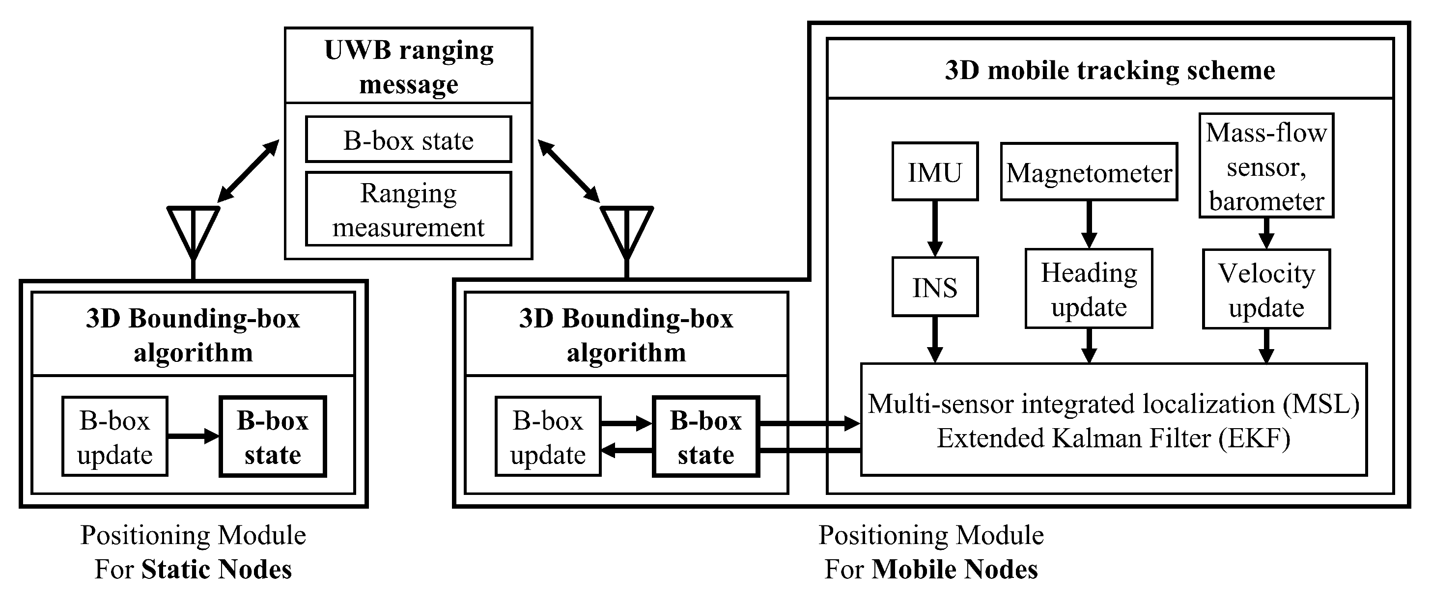
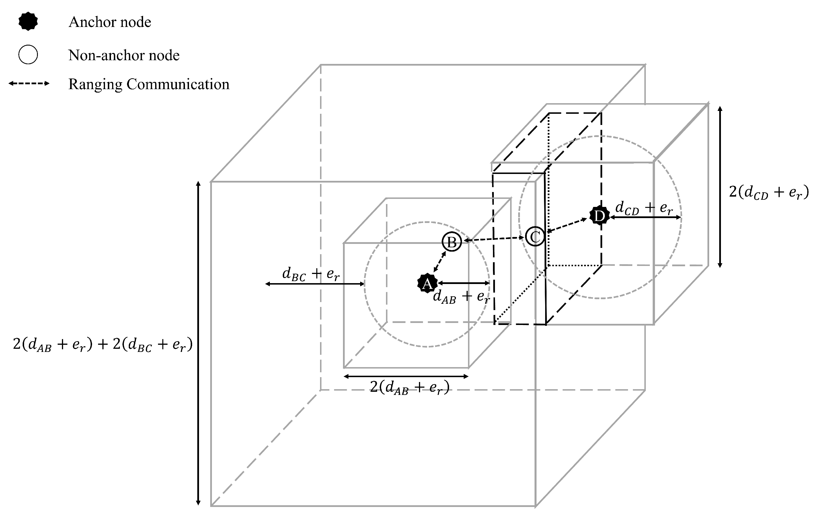
3.1. IR-UWB Based 3D Multi-Hop Self Localization with Bounding-Box and Mobile Tracking Scheme

To perform the greedy forwarding strategy, the location information of network nodes is required. We propose a fully-distributed 3D multi-hop self localization algorithm as shown in Figure 2. Every node participates in the 3D bounding-box algorithm, which describes the statistically possible residing region of nodes as the B-box state [2,12,13]. By exchanging UWB ranging messages containing the nodes’ current B-box states and ranging measurements between two nodes, these nodes update their previous B-box states based on the ranging measurement result and the other node’s B-box state. In the 3D mobile tracking scheme, mobile nodes also estimate their movement by constructing the multi-sensor integrated localization (MSL) extended Kalman filter (EKF) [14] and use it to update their B-box states. Using the inertial measurement unit (IMU) data, the mobile nodes’ navigation states are predicted from the inertial navigation system (INS) mechanism [15]. The obtained navigation states are used to construct the EKF system model by applying the INS error model [16]. Then, magnetometer, mass-flow sensor, and barometer data are calibrated and utilized in the heading and velocity updates in the EKF [14]. After the navigation state estimates are updated, the B-box states of the mobile nodes are updated and provided to static nodes through the UWB ranging message exchange procedure. The presented IR-UWB-based 3D multi-hop self localization with bounding-box and the mobile tracking scheme provides significant improvement of the network’s overall positioning accuracy.
The overall 3D B-box determination process is illustrated in Figure 3. Node C’s B-box state vector b C is determined when receiving B-box information b B from another node B in the ranging message exchange as follows:
b C = [ max ( x C l w b , x B l w b ( d C B + e r ) ) min ( x C u p b , x B u p b + ( d C B + e r ) ) max ( y C l w b , y B l w b ( d C B + e r ) ) min ( y C u p b , y B u p b + ( d C B + e r ) ) max ( z C l w b , z B l w b ( d C B + e r ) ) min ( z C u p b , z B u p b + ( d C B + e r ) ) ] T
where x C l w b , y C l w b , z C l w b are lower bounds of b C and x C u p b , y C u p b , z C u p b are upper bounds of b C , d C B is the measured distance between C and B, and e r is the maximum ranging error value. e r is set to 50 cm in this paper’s simulations, referring to the Decawave DW1000 module ranging measurements [17].
Mobile nodes also update their B-box states based on the position estimation of the mobile tracking scheme in addition to the previous B-box state update. Using the IMU data, the INS mechanization [15] provides the mobile nodes’ navigation-state prediction. Applying the INS error model [16], the EKF system model is constructed as in [14]. Calibrating and utilizing the measurements of the magnetometer, mass-flow sensor and barometer, the predicted INS heading and velocity states are updated in the MSL EKF [14]. The magnetometer data are utilized to compute the magnetometer heading and to build the heading update model in the EKF. Using the mass-flow sensor data, the velocity update in the EKF is processed. For quality control (QC) of the velocity updates, the barometer data are computed to detect height changes. After the heading and velocity updates, the MSL EKF provides the mobile nodes’ position, velocity and heading solution. For more details of the MSL EKF-based mobile tracking process, refer to Refs. [14,18,19].
Finally, using the position solutions of the MSL EKF, mobile node M’s B-box state vector b M is updated at every mobile tracking period of interval T M as follows:
b M = [ x M l w b + x m e p x M u p b + x m + e p y M l w b + y m e p y M u p b + y m + e p z M l w b + z m e p z M u p b + z m + e p ] T
Here, x M l w b , y M l w b , z M l w b are lower bounds of b M and x M u p b , y M u p b , z M u p b are upper bounds of b M . x m , y m and z m are the estimated position displacements between the current interval and the previous interval computed from the MSL EKF position solution. e p is the maximum statistical position error during one mobile tracking period, T M . In all simulations, e p is set proportional to 30 cm for 1 s of T M , according to the experimental statistics of position errors presented in [14]. The updated B-box states of mobile nodes improve static nodes’ positioning accuracy when UWB ranging messages exchange, further enhancing the network’s overall estimated location resolution.

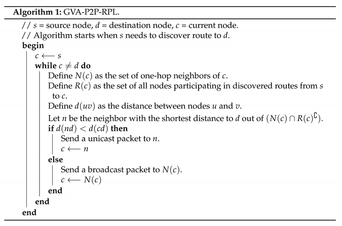
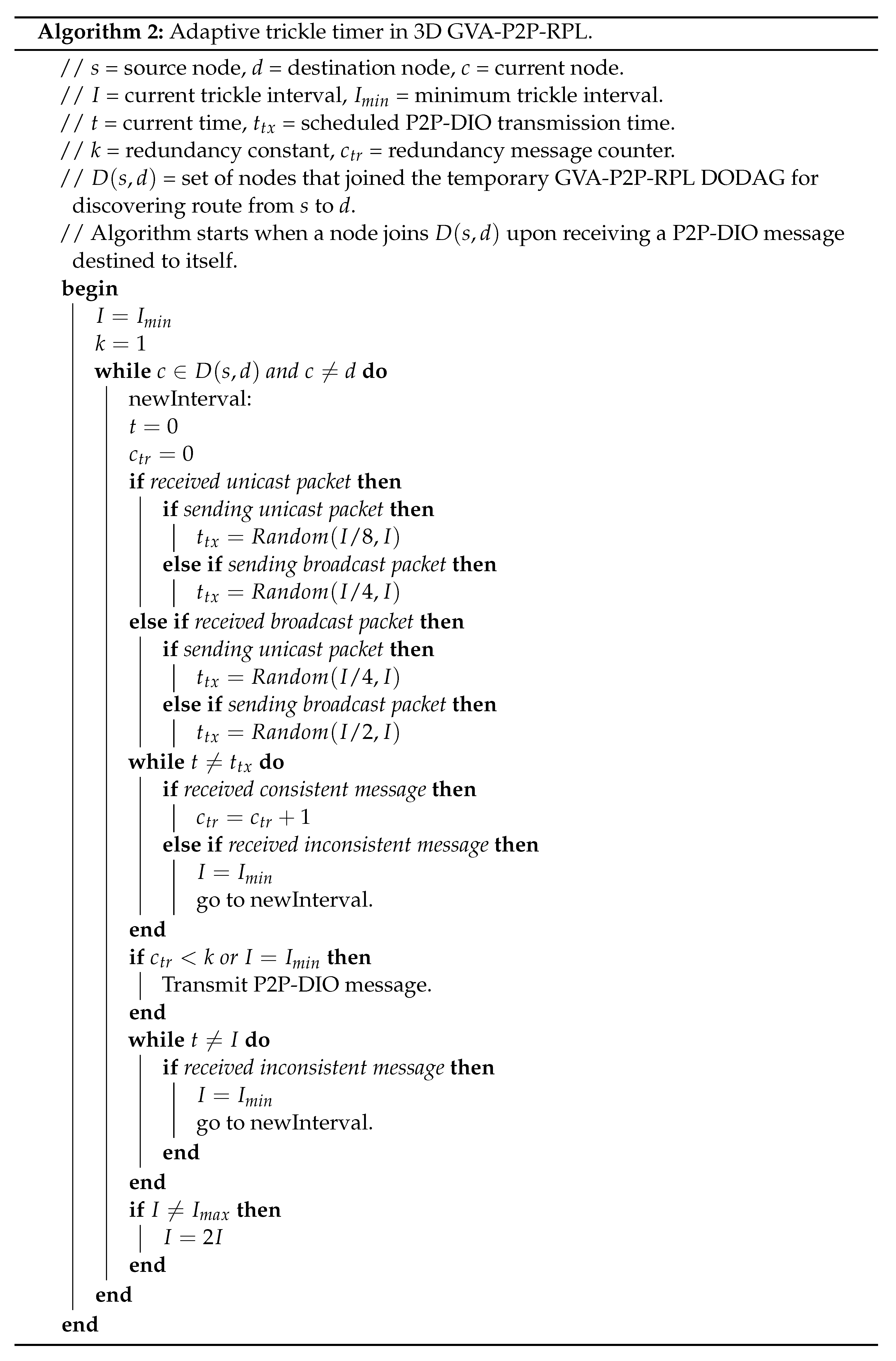
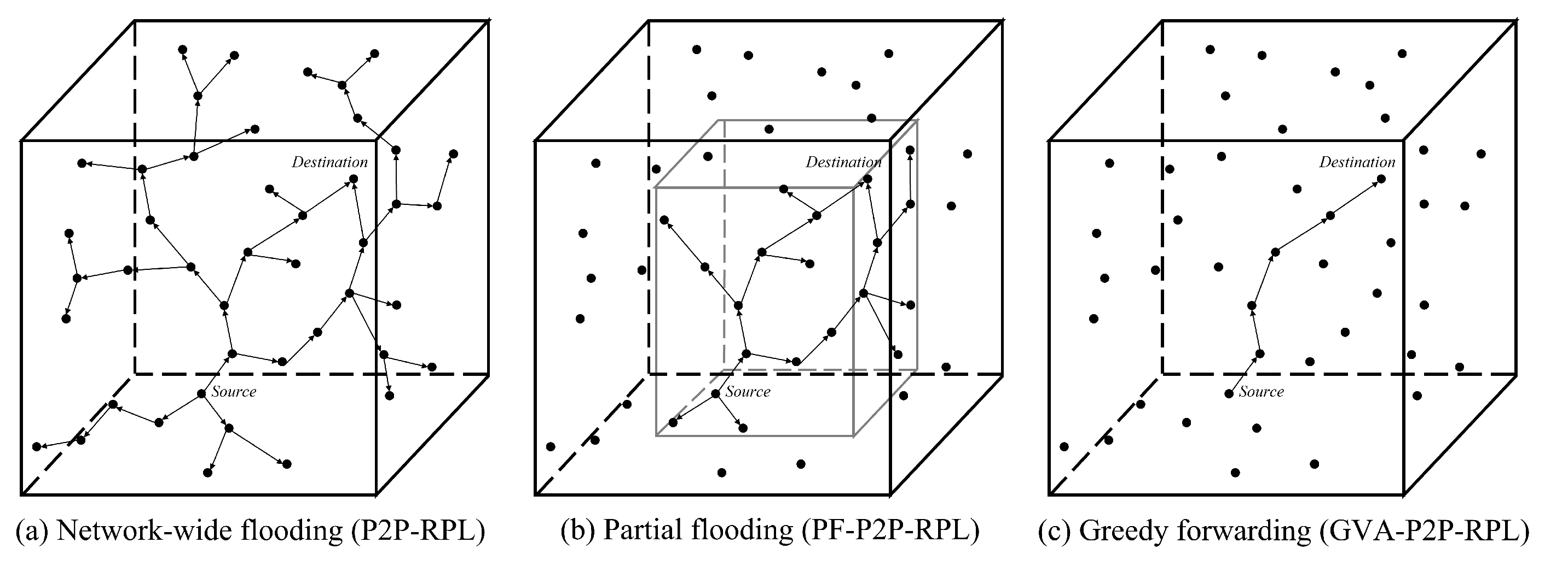
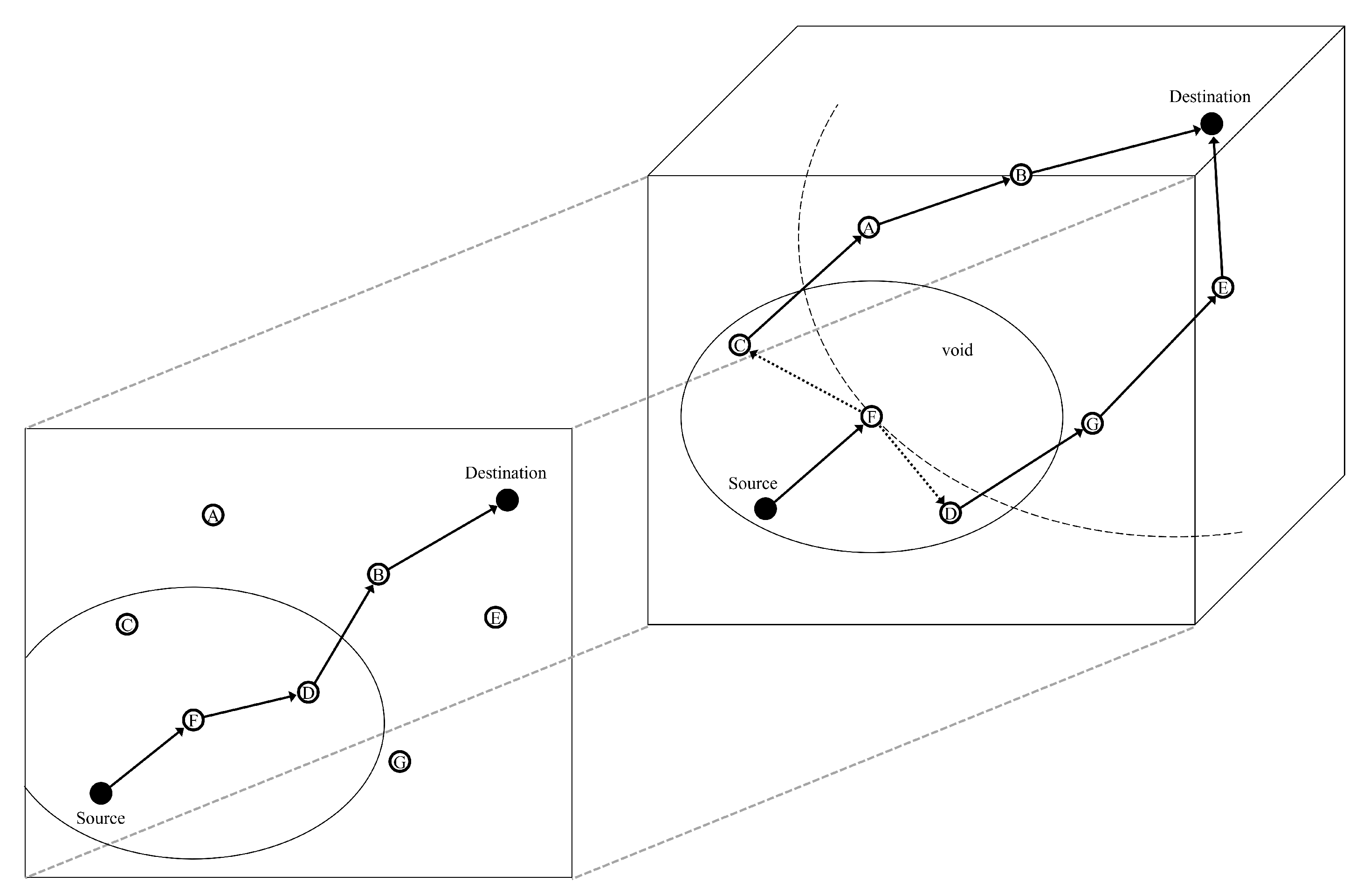
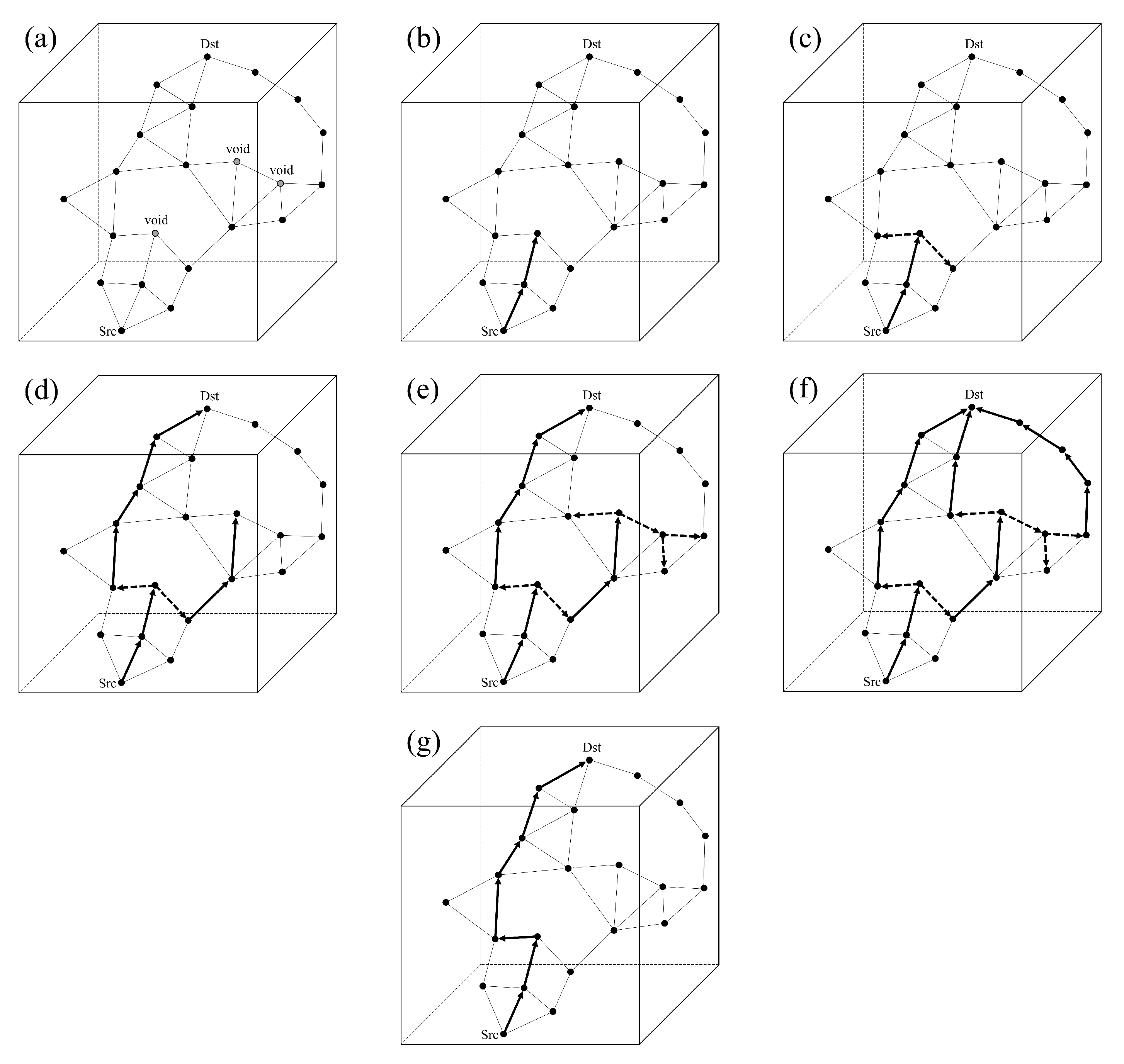
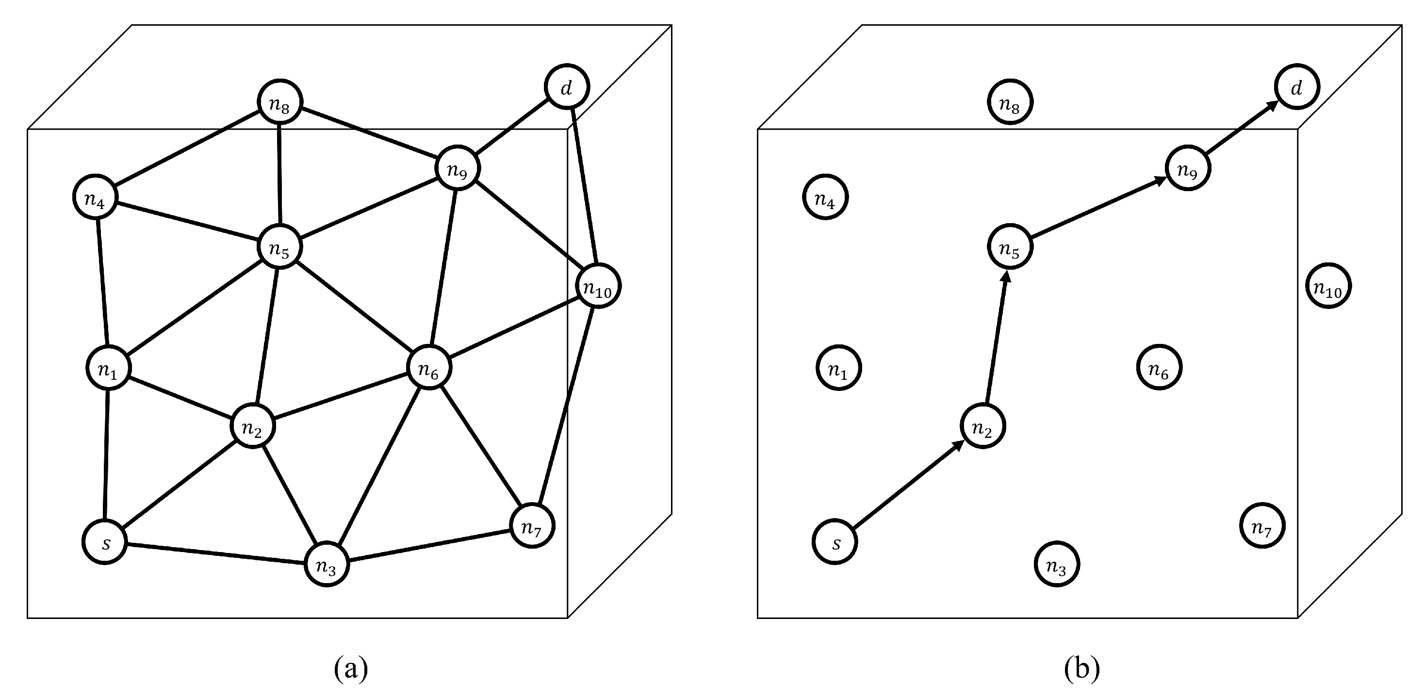
3.2. Greedy Forwarding and Void Handling Point-to-Point RPL in 3D Indoor Environments

In this subsection, we propose a reactive geographic routing protocol called GVA-P2P-RPL for 3D environments, which improves the P2P-RPL [1] standard by forwarding P2P-DIO messages in a greedy manner when it is possible to reduce the routing overheads. To greedily choose the next hop, the location information acquired from the previous multi-hop positioning system is utilized. When expanding the network simulation environments from 2D to 3D, greedy forwarding techniques generally encounter local minimum or void (routing hole) situations more often in which a packet cannot be forwarded to the next closer hop to the destination. The internode connectivity is weakened as the network topology is transformed from 2D to 3D [7]. Figure 4 illustrates that the void problem occurs more often when the network dimensionality is expanded from 2D to 3D. Coverage and connectivity adversities in 3D networks are further addressed and explained in [4]. To overcome the local minimum problem, GVA-P2P-RPL simply switches back to the standard P2P-RPL’s flooding strategy until a neighbor node closer to the destination is discovered. When recovered from the local minimum, GVA-P2P-RPL again greedily forwards P2P-DIO messages. Adaptive trickle timer (ATT) in 3D GVA-P2P-RPL is also newly presented to reduce the route discovery time and avoid collisions of P2P-DIO messages. Since GVA-P2P-RPL has only a few nodes participating in the route discovery process, contention among nodes is alleviated and redundant message suppression is less necessary. Therefore, it is reasonable to use a smaller minimum trickle timer interval I m i n parameter value than the standard trickle algorithm. As closer nodes to the destination are more probable of constructing the shortest path by intuition, ATT gives higher transmission priority to those nodes by shortening their listen-only periods. The shortened listen-only periods also provide better collision avoidance because the range of randomly selected transmission time becomes wider [20].
The general forwarding scheme of GVA-P2P-RPL is depicted in Figure 5. At first, a node that has a P2P-DIO message to forward creates a neighbor node list that does not contain any neighbor existing in the previously discovered routes to avoid the loop. Then, it sets the next hop address as the closest neighbor node’s unicast address to the destination when such a neighbor node exists as the solid arrows in Figure 5b,d,f. If not, the forwarding node sets the next hop address as the broadcast address to recover from the local minimum as the solid dashed arrows in Figure 5c,e. By repeating this process from the source node to the destination node, reliable route discovery is completed and several different routes may be found. The destination node records all the discovered routes and chooses the best route among them according to the RPL objective function set in the initial DODAG configuration as the solid arrow route in Figure 5g. The best route is piggybacked in the P2P-DRO (P2P discovery reply object) [1] message and sent backwards to the source. Upon receiving the P2P-DRO message, the source sends data packets along the discovered route. Detailed next-hop selection and packet forwarding algorithms of GVA-P2P-RPL are shown in Algorithm 1. In implementation, we modified the route discovery option (RDO) [1] field, a RPL control message option defined for P2P-DIO messages, by piggybacking the target’s location information to enable the greedy forwarding operation. Electronics 11 00625 i001
P2P-RPL uses the standard trickle timer algorithm [8] to effectively flood P2P-DIO messages throughout the network. Because all network nodes participate in the route discovery, P2P-RPL generally reaches the destination quickly. In GVA-P2P-RPL, only a few nodes in the whole network participate in the route discovery, which reduces the routing overheads but results in longer route discovery time. The purpose of the standard trickle algorithm is to effectively suppress redundant message transmissions [21]. P2P-RPL requires such a suppression mechanism to be strictly in action because all nodes participate in the route discovery. In 3D environments, the number of participating nodes in P2P-RPL increases as the dimensionality is expanded from 2D. Compared to P2P-RPL, GVA-P2P-RPL significantly reduces redundant messages, especially when P2P-DIO messages are greedily forwarded. In such cases, the suppression mechanism is unnecessary, as no contention exists. Using this advantage, we present the adaptive trickle timer (ATT) in 3D GVA-P2P-RPL, which uses a shorter minimum trickle timer interval I m i n parameter value by adaptively changing the listen-only periods to reduce the long route discovery time. The DODAG configuration option [9] field, a RPL control message option that distributes configuration information of the current DODAG, is modified to piggyback a halved I m i n value in implementation. With ATT, GVA-P2P-RPL completes its route discovery procedure much faster than P2P-RPL without the need for additional nodes. The shortened listen-only periods provide better P2P-DIO message collision avoidance among one-hop neighbors, too.
Figure 6 and Figure 7 show how ATT shortens the route discovery time and provides collision avoidance effects compared to P2P-RPL. P2P-RPL, using the standard trickle algorithm, reaches the destination d when node n 9 first transmits its P2P-DIO message as shown in Figure 7. P2P-RPL more likely faces P2P-DIO message collisions as a large number of nodes participate in contentions and listen-only periods are relatively long. GVA-P2P-RPL, using the same standard trickle algorithm, reaches the destination also when node n 9 first transmits its P2P-DIO message as shown in Figure 8. The P2P-DIO message transmission of node n 9 takes more time in the latter case because P2P-RPL utilizes all network nodes in the route discovery process. Therefore, P2P-RPL has a far better chance of propagating P2P-DIO messages earlier than GVA-P2P-RPL with the standard trickle algorithm. To reduce such delays, GVA-P2P-RPL with ATT in Figure 9 has a shorter I m i n parameter value and adaptively shortens its listen-only periods, leading to a higher probability of passing P2P-DIO messages earlier than before. All simulations and example cases in this paper use a half-length I m i n value in ATT, compared to the standard trickle. The detailed algorithm of ATT is shown in Algorithm 2. With this approach, GVA-P2P-RPL reaches the destination when node n 9 first transmits its P2P-DIO message, and hence the route discovery completes faster than P2P-RPL. Shortened listen-only periods also provide a far better chance for randomly scheduled transmission times to be different, leading to collision avoidance effects. Electronics 11 00625 i002
To demonstrate how ATT works when four nodes within transmission range of each other compete for P2P-DIO transmission, another example P2P route discovery case of Figure 10 is shown. Nodes n 5 , n 6 , n 7 and n 8 join P2P-RPL DODAG at similar times as depicted in the timings of Figure 11. n 5 and n 6 receive the broadcast P2P-DIO message from n 4 . Each of n 7 and n 8 receives a unicast P2P-DIO message from n 2 and n 3 , respectively. n 5 and n 7 have no neighbor closer to d, and therefore schedule a broadcast P2P-DIO message. n 6 and n 8 have a neighbor closer to d and therefore schedule a unicast P2P-DIO message to n 9 and n 10 , each, respectively. In such a case, ATT gives the highest transmission priority to n 8 by shortening the listen-only period of n 8 the most. n 6 and n 7 are given the next highest transmission priority, and their listen-only periods are shortened according to priority values. For n 5 , its listen-only period is unchanged, granting the lowest transmission priority. As a result, ATT propagates P2P-DIO messages faster through node n 8 and reaches the destination d earlier than when the standard trickle algorithm is used, while the discovered route s- n 3 - n 8 - n 10 -d still achieves the shortest hop count.

4. Performance Evaluation

The performance results of the cooperative multi-hop self-positioning system and the GVA-P2P-RPL protocol in 3D IR-UWB networks are evaluated. Both experiments are simulated by configuring the radio characteristics of Decawave’s DW1000 UWB radio chip [22], which follows the IEEE 802.15.4 standard [23,24]. To apply real UWB device’s network delay characteristics in the routing simulations, we calculated transmission delays of the P2P-DIO message and P2P-DRO message according to the model of the UWB frame transmission time (Figure 12) in the configured UWB parameter setting (Table 2). According to the model, a P2P-DIO message of 66 bytes payload requires PPDU (PHY protocol data unit) frame transmission delay of 276.7 us and a P2P-DRO message of 38 bytes requires a PPDU frame transmission delay of 233.6 us. To validate the PPDU frame transmission delay calculation results of the model, a testbed experiment with Decawave DW1000 modules was conducted, where we measured the end-to-end network delay for hop lengths varying from 1 to 4 between the source node and the destination node. As a result, an average one-hop network delay of 259.3 us was obtained. Since the average of the calculated P2P-DIO message and P2P-DRO message transmission delay is 255.2 us, the average of the sum of the one-hop processing delay, queuing delay and propagation delay is approximately 4.1 us.
The self-positioning simulation is implemented and conducted on Java. For routing performance evaluation, the route discovery success ratio, routing overheads, route discovery time and hop count are selected as the main routing performance metrics. The route discovery success ratio result shows the reliable routing ability of the proposed algorithm in both void-free and void-apparent networks. The low routing overhead result is presented to prove the high energy efficiency for operations. The low route discovery time is observed, which shows the fast routing ability in real-time implementations. The proposed algorithm achieves a slightly higher hop count than the other compared routing protocols, which indicates that it can still discover near-optimal routes with much low routing overheads. P2P-RPL, PF-P2P-RPL and ER-RPL results are compared to prove the strengths of the proposed GVA-P2P-RPL routing algorithm against the state-of-the-art RPL-based P2P routing methods. The routing simulations are implemented on the Cooja network simulator on the Contiki operating system platform [25]. P2P-RPL simulation is conducted on the P2P-RPL standard implementation [26] which is a modified version of the ContikiRPL [25] library. PF-P2P-RPL, ER-RPL and GVA-P2P-RPL simulations are conducted by modifying the P2P-RPL standard implementation.

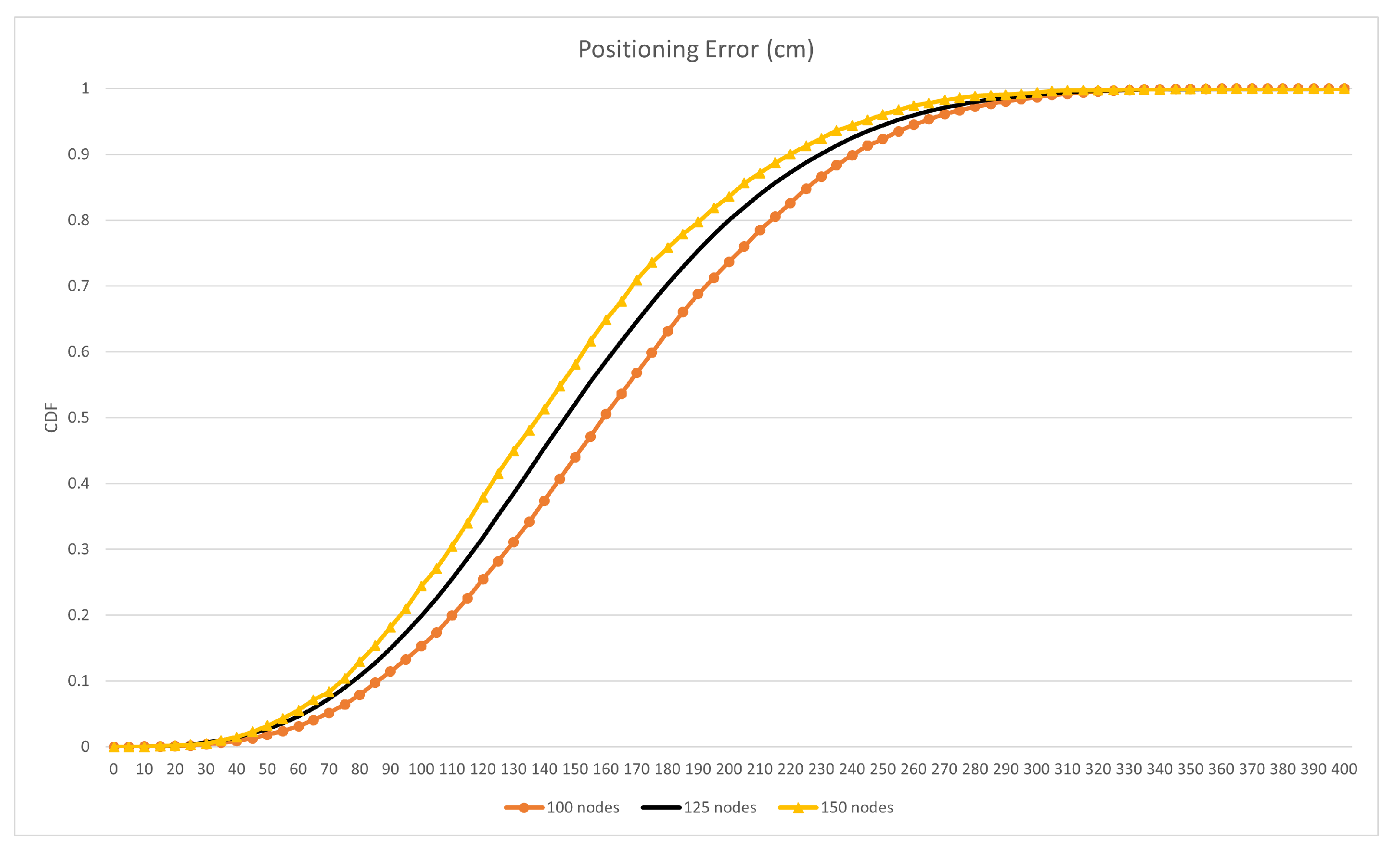
4.1. IR-UWB Based 3D Multi-Hop Self Localization with Bounding-Box and Mobile Tracking Scheme

The positioning error simulation result of the proposed IR-UWB based 3D multi-hop self-positioning system is shown in Figure 13 in a CDF form. One hundred simulation runs are conducted for three different numbers of static node cases: 100, 125, and 150. The static nodes are deployed in a grid pattern with (±5 m, ±5 m, ±5 m) randomness. The network size is 75 m × 75 m × 75 m, the same as the routing simulation environment configuration. Eight mobile nodes move around the network. The maximum ranging error value e r is set to 50 cm according to the Decawave DW1000 module ranging measurements [17]. The maximum mobile tracking error value e p is set to 30 cm/s, referring to the experimental statistics of the position errors presented in [14]. The average positioning error values for three cases are 162 cm, 151 cm, and 143 cm, respectively. In a simulation where no mobile nodes are deployed, the positioning error result of 2791 cm was acquired in the case of 125 static nodes. With the mobile nodes, roaming around the network to provide the static nodes with their real-time B-box states and ranging measurements, the positioning results are significantly improved, compared to the case where no mobile nodes participate. In all routing simulations, the acquired statistical positioning error information of the 125 static nodes case is used for each node location estimation and the greedy next-hop selection procedure.

4.2. Greedy Forwarding and Void Handling Point-to-Point RPL in 3D Indoor Environments

For routing simulations, 10 simulation runs are conducted for 125 nodes and 98 nodes with void, where each run has 235 different P2P traffic cases. All routing simulation parameter settings are listed in Table 3.
Routing performance is evaluated for the following six different performance metrics:
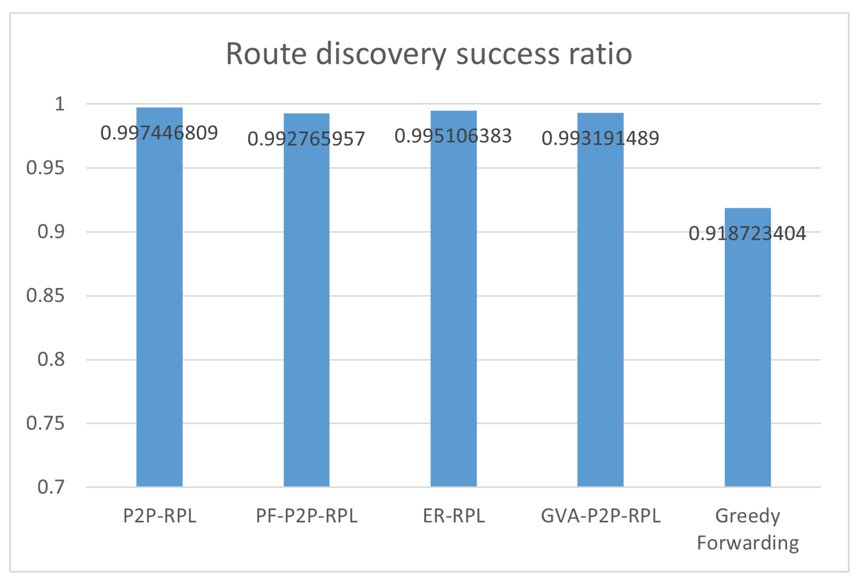
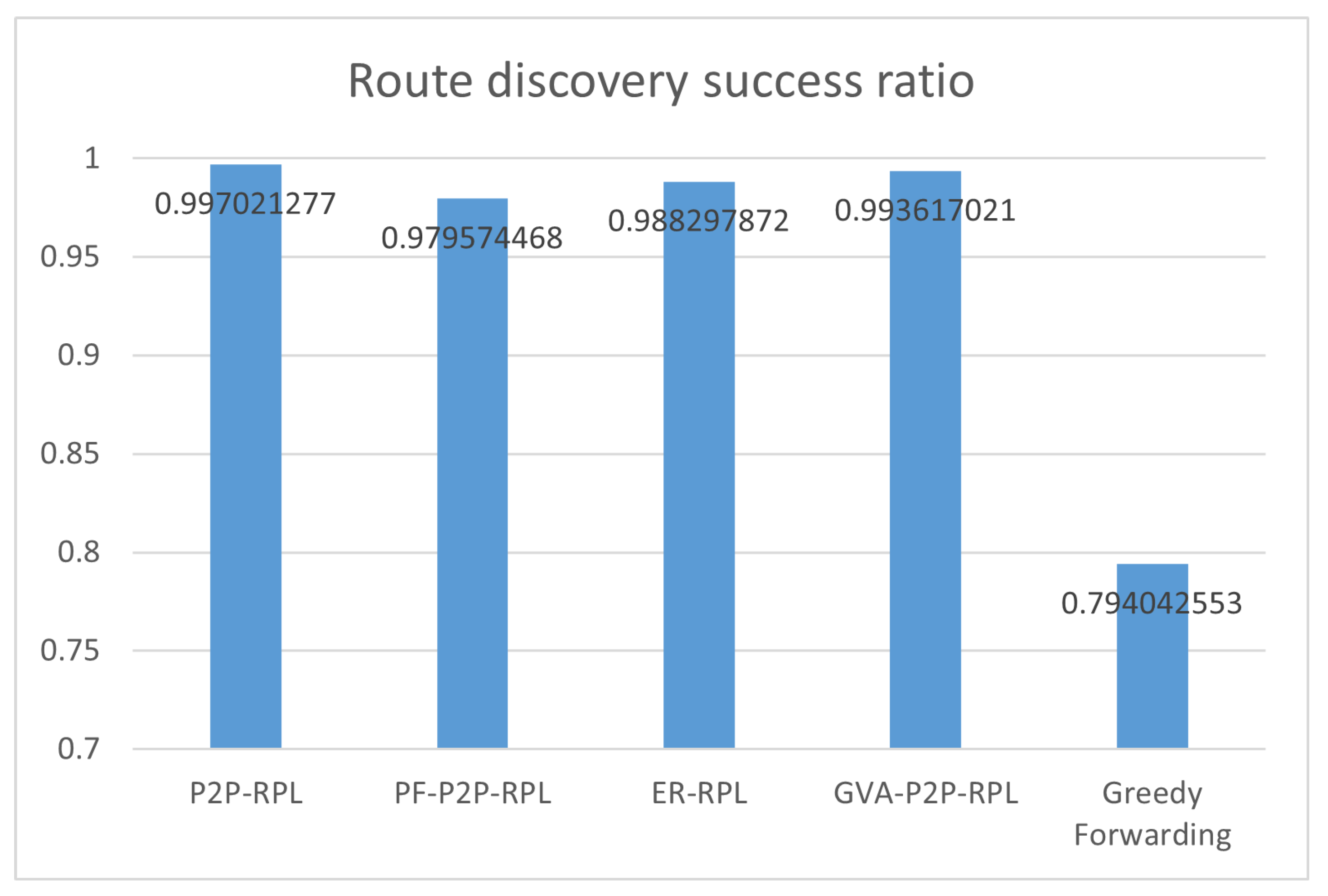
  • Route discovery success ratio is the average ratio of the number of successful P2P route discovery attempts to that of the total P2P route discovery attempts.
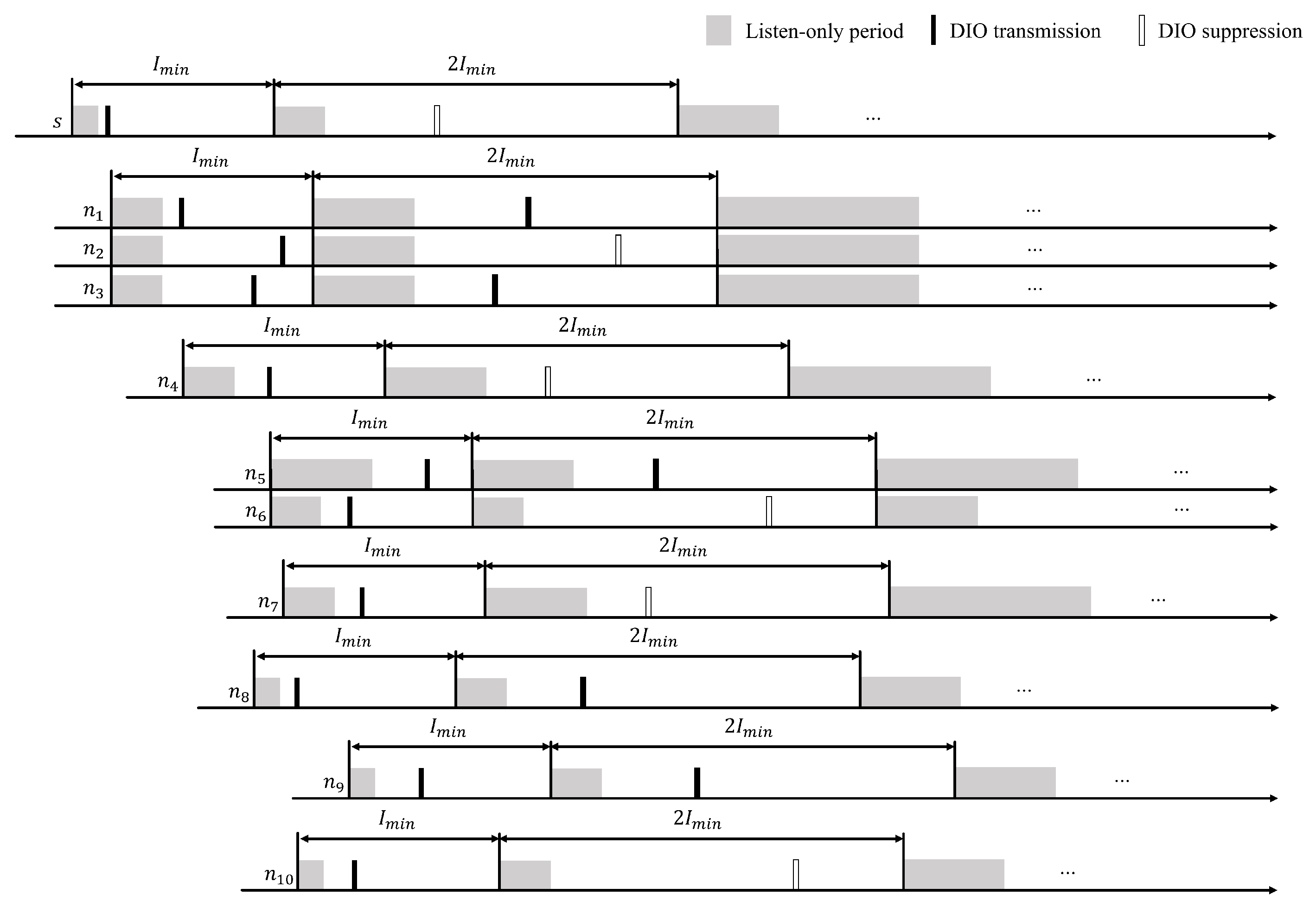
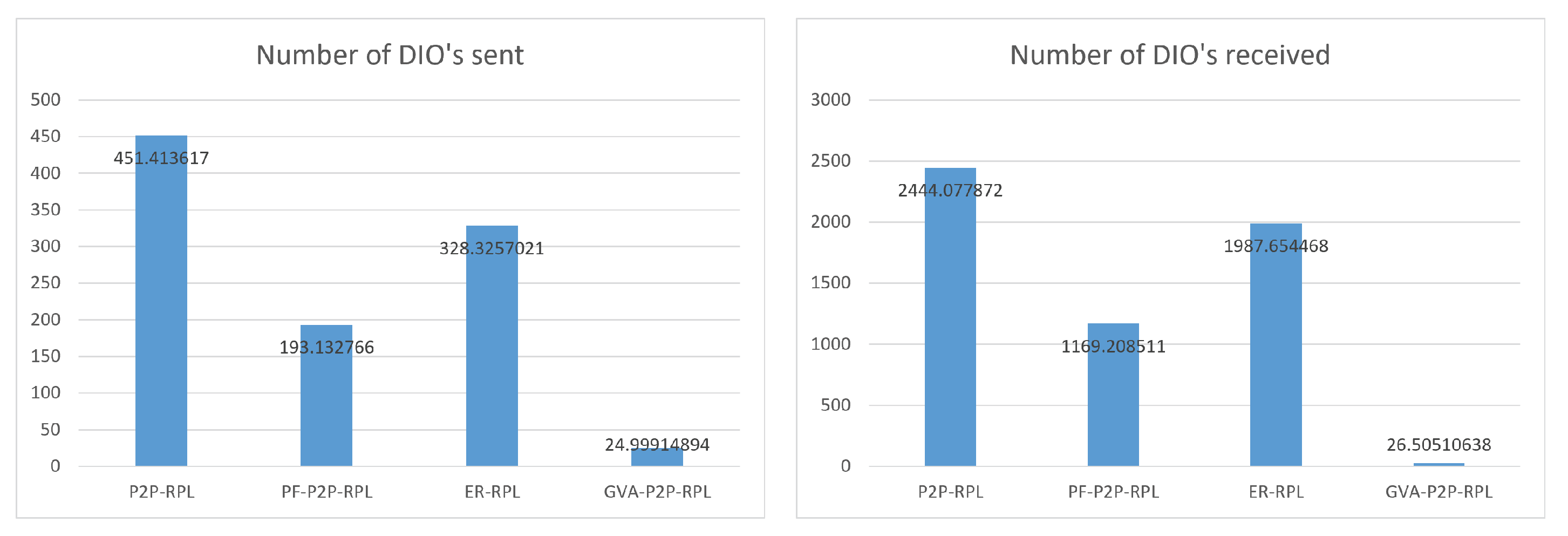
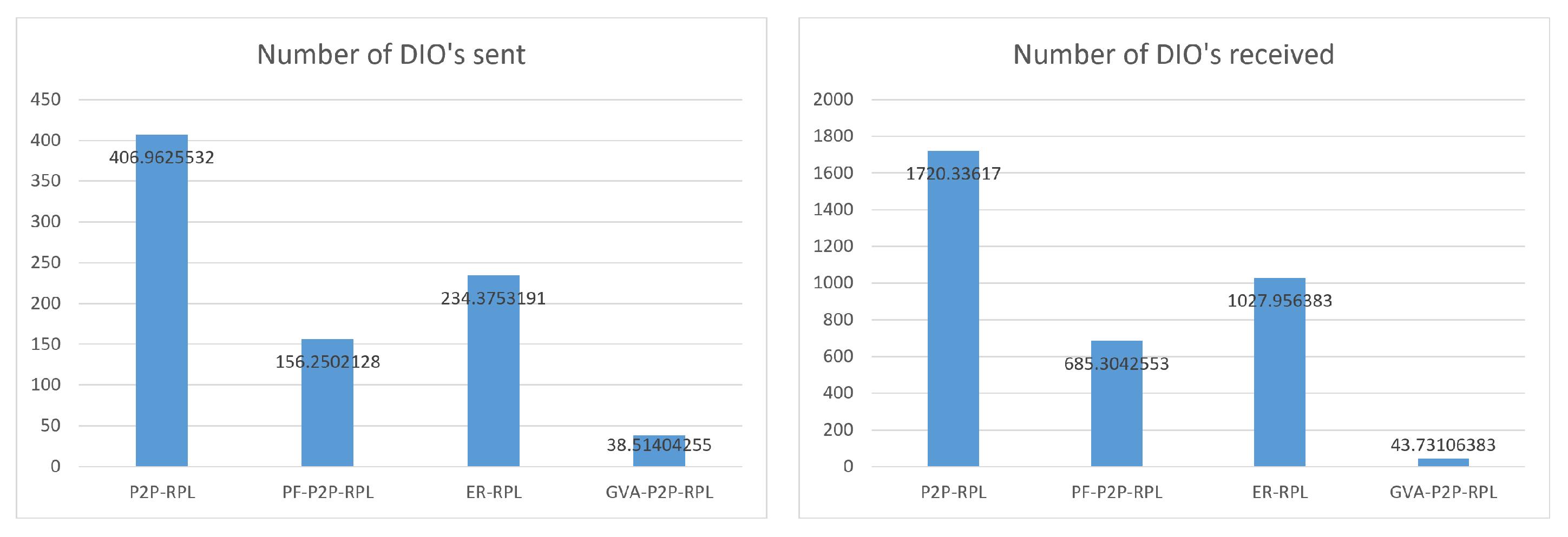
  • Number of DIO’s sent is the average number of P2P-DIO messages sent by network nodes during the route discovery process.
  • Number of DIO’s received is the average number of P2P-DIO messages received by network nodes during the route discovery process.
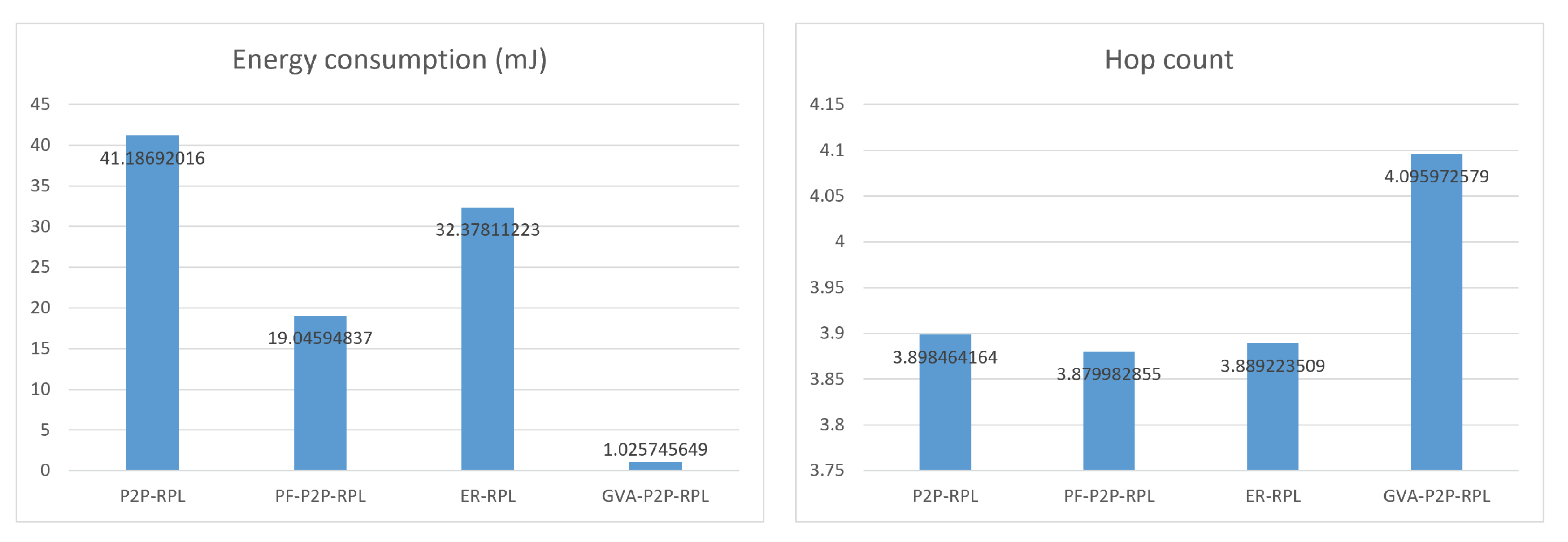
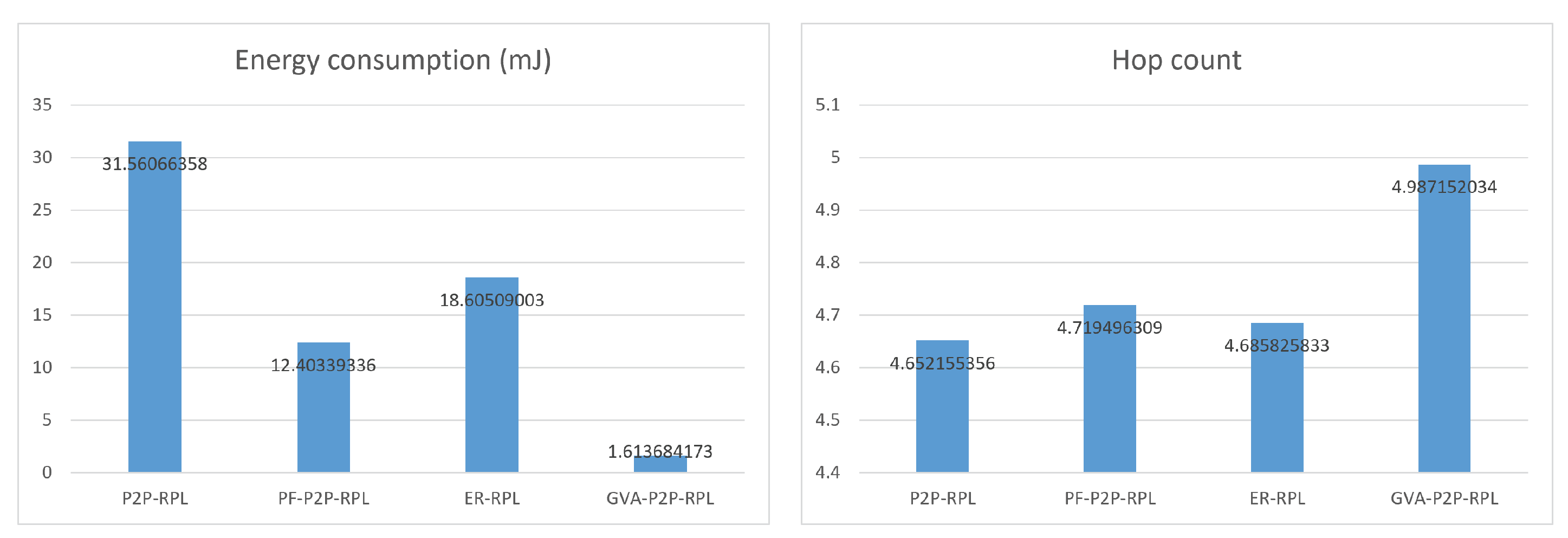
  • Energy consumption is the average energy consumed during the whole route discovery interval, which is calculated according to the radio model parameters addressed in Table 2.
  • Hop count is the average path length of discovered routes.
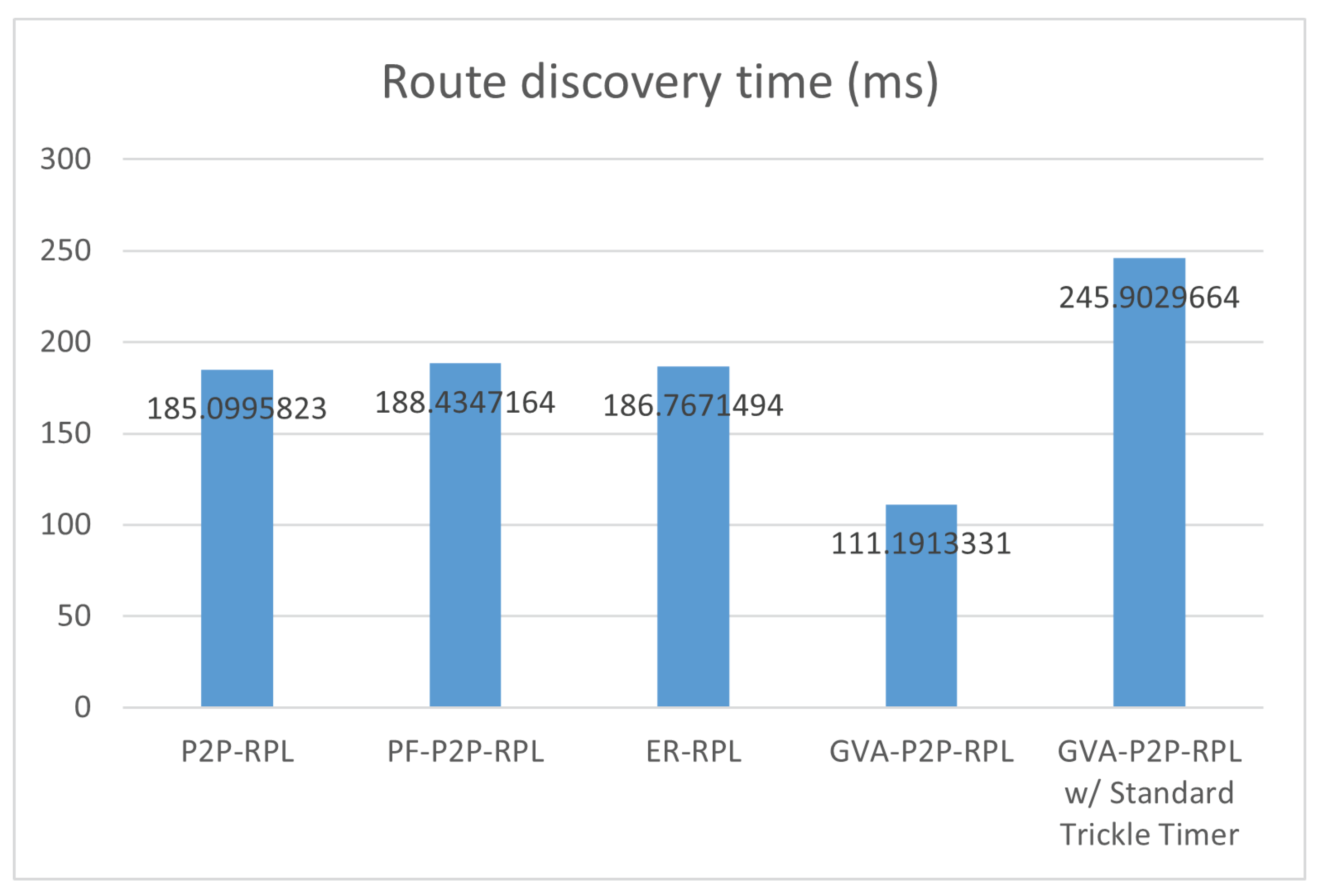
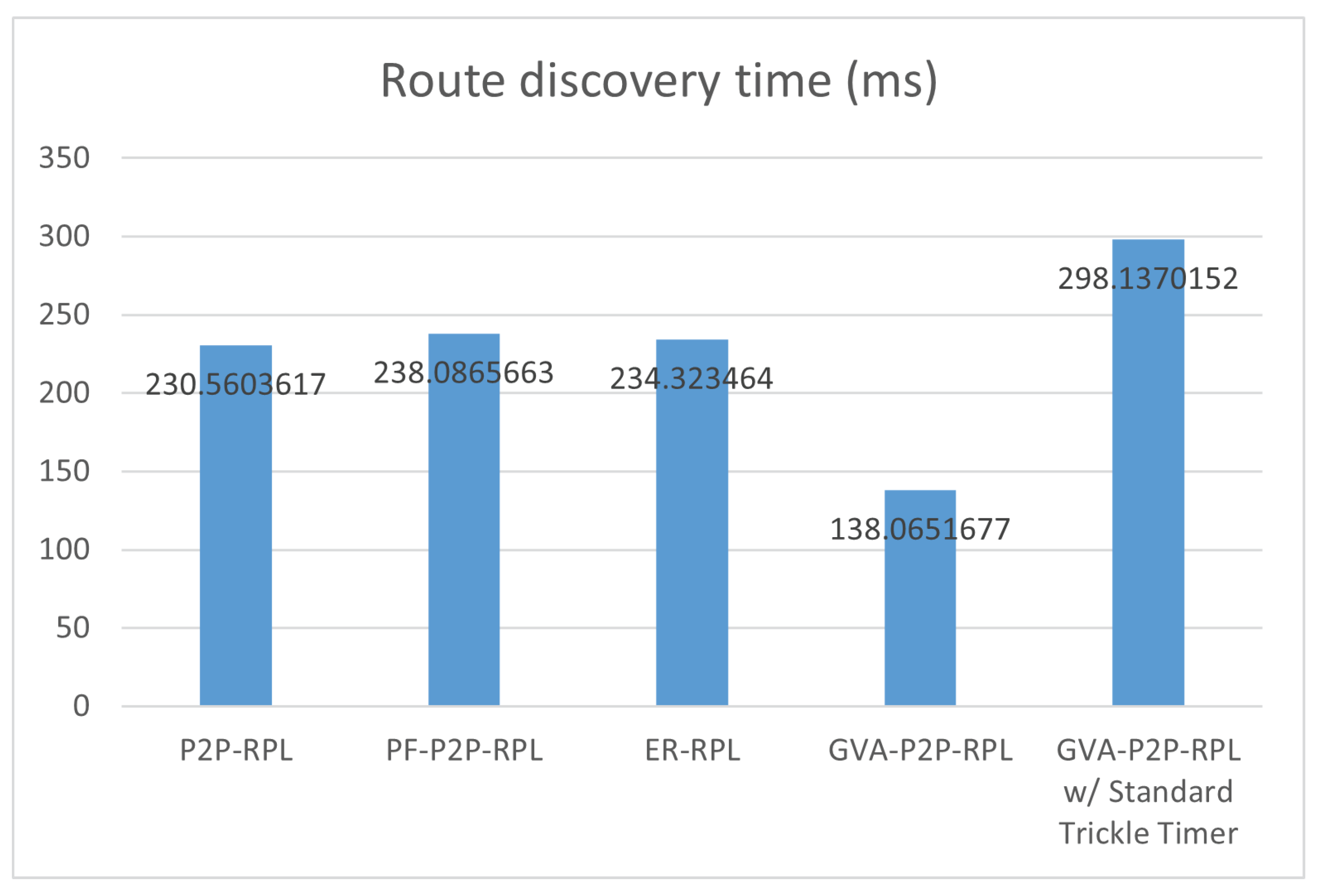
  • The route discovery time is the average time passed from the route discovery initialization of the source node to the first receipt of any P2P-DIO message at the destination node.

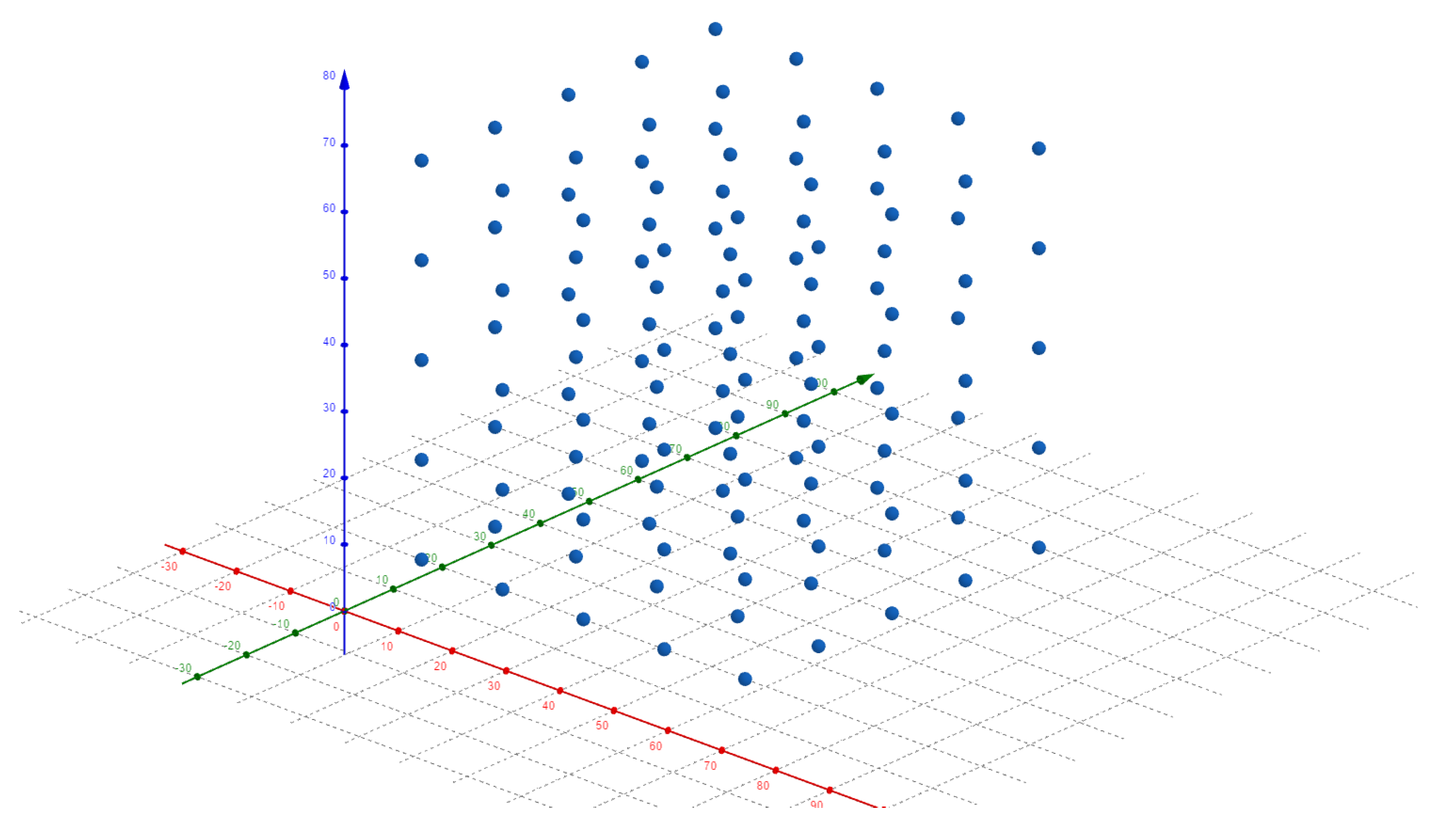
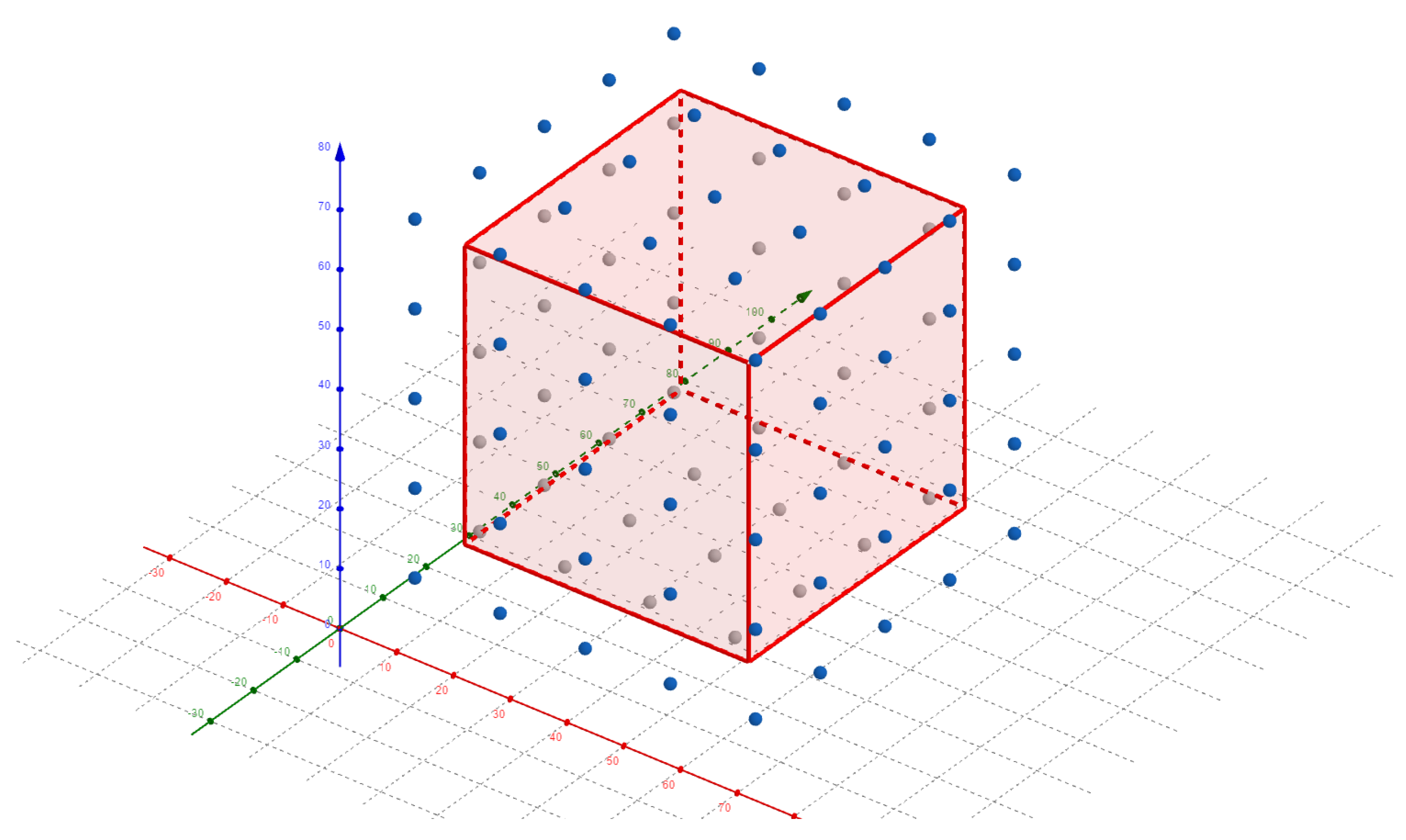
4.2.1. 125 Node Grid Deployment in 75 m × 75 m × 75 m Network Configuration

Figure 14 depicts the network node deployment of 125 nodes. Nodes are located in a grid pattern with (±5 m, ±5 m, ±5 m) of randomness.
Figure 15 shows the result of the route discovery success ratio. P2P-RPL, PF-P2P-RPL, ER-RPL, GVA-P2P-RPL, and greedy forwarding have about 99.7%, 99.3%, 99.5%, 99.3%, and 91.9% of the route discovery success ratio, respectively. Since the local minima led to routing failures, the greedy forwarding case achieved a 7.4% lower route discovery success ratio than GVA-P2P-RPL. This result shows that the recovery mode of GVA-P2P-RPL locally broadcasts P2P-DIO messages when void nodes are encountered. The proposed GVA-P2P-RPL protocol is as reliable as P2P-RPL in route discovery for 3D environments where local minimum problems are observed more often than for 2D.
Figure 16 shows the results of the number of P2P-DIO messages sent and number of P2P-DIO messages received. As shown, the routing overhead result of GVA-P2P-RPL outperforms that of P2P-RPL, PF-P2P-RPL and ER-RPL. GVA-P2P-RPL reduces about 94.5%, 87.1% and 92.4% of the number of DIOs sent, compared to P2P-RPL, PF-P2P-RPL and ER-RPL, respectively, and about 98.9%, 97.7% and 98.7% of the number of DIOs received, compared to P2P-RPL, PF-P2P-RPL and ER-RPL, respectively.
Figure 17 shows the result of energy consumption and hop count. In the same sense as the overall routing overheads of GVA-P2P-RPL being reduced compared to those of P2P-RPL, PF-P2P-RPL and ER-RPL, the energy consumption results of GVA-P2P-RPL are also significantly reduced. GVA-P2P-RPL reduces about 97.5%, 94.6% and 96.8% of the energy consumption compared to P2P-RPL, PF-P2P-RPL and ER-RPL, respectively. The average hop count of GVA-P2P-RPL is about 0.198 hops longer than that of P2P-RPL, about 0.216 hops longer than that of PF-P2P-RPL and about 0.207 hops longer than that of ER-RPL. GVA-P2P-RPL greedily selects the closest neighbor node to the destination whenever greedy forwarding is possible, and it is possible that other neighbor nodes that may construct shorter routes are not selected. Such cases occur when P2P route discovery encounters the local minimum. As a result, GVA-P2P-RPL leads to a slightly higher hop count value of the discovered route than P2P-RPL, PF-P2P-RPL and ER-RPL.
Figure 18 shows the result of the route discovery time. The average route discovery time of GVA-P2P-RPL with the adaptive trickle timer (ATT) is about 39.9% less than that of P2P-RPL, about 41.0% less than that of PF-P2P-RPL, about 40.5% less than that of ER-RPL, and about 54.8% less than that of GVA-P2P-RPL with the standard trickle algorithm. As the trickle algorithm is used in the routing simulations unlike the previous end-to-end network delay measurement experiment, the route discovery time results are in the range of 100 to 250 ms, which is much longer than the average network delay result of 259.3 us. With the standard trickle algorithm, P2P-RPL, PF-P2P-RPL and ER-RPL outperform GVA-P2P-RPL. That is, more nodes participating in route discovery procedure leads to a higher probability of scheduling an earlier P2P-DIO message transmission time in P2P-RPL, PF-P2P-RPL and ER-RPL. ATT uses 2 5 ms as its I m i n parameter value, while the standard trickle algorithm uses 2 6 ms. ATT also gives higher transmission priority to nodes closer to the destination by setting these nodes’ listen-only periods to be shorter. As explained in the previous section, these two parameter value changes are reasonable since GVA-P2P-RPL has far fewer nodes participating in the route discovery procedure and fewer contentions among the one-hop neighbor nodes. As a result, the shorter route discovery time is achieved compared to P2P-RPL, PF-P2P-RPL and ER-RPL.

4.2.2. 98 Node Grid Deployment with Void Area in 75 m × 75 m × 75 m Network Configuration

Figure 19 shows the network node deployment of 98 nodes with a large void area depicted as the cuboid where no node resides inside. This deployment is different from the previous 125 nodes grid deployment in that 27 nodes that are not near the floor, walls and ceiling are not available for route discovery. This special simulation case with the big void cuboid is presented to demonstrate how well the proposed GVA-P2P-RPL recovers from the local minima by locally broadcasting P2P-DIO messages when the local minimum is encountered in real-life 3D environments.
Figure 20 shows the result of the route discovery success ratio. P2P-RPL, PF-P2P-RPL, ER-RPL, GVA-P2P-RPL, and greedy forwarding have about 99.7%, 98.0%, 98.8%, 99.4%, and 79.4% of the success ratio, respectively. As the void cuboid is inserted into the network deployment, the local minima occur more often, and thus the greedy forwarding case achieved 20.0% lower route discovery success ratio compared to GVA-P2P-RPL. Even with the big void cuboid, GVA-P2P-RPL achieved route discovery success ratio almost as high as P2P-RPL.
Figure 21 shows the results of the number of P2P-DIO messages sent and the number of P2P-DIO messages received. As shown, the routing overhead result of GVA-P2P-RPL still outperforms that of P2P-RPL, PF-P2P-RPL and ER-RPL in the presence of the void cuboid. GVA-P2P-RPL reduces about 90.5%, 75.4% and 83.6% of the number of DIOs sent, compared to P2P-RPL, PF-P2P-RPL and ER-RPL, respectively, and about 97.5%, 93.6% and 95.7% of the number of DIOs received, compared to P2P-RPL, PF-P2P-RPL and ER-RPL, respectively.
Figure 22 shows the results of the energy consumption and hop count in the presence of the void cuboid. The energy consumption results of GVA-P2P-RPL are also greatly reduced to be the same as the routing overhead results. GVA-P2P-RPL reduces about 94.9%, 87.0% and 91.3% of the energy consumption compared to P2P-RPL, PF-P2P-RPL and ER-RPL, respectively. The average hop count of GVA-P2P-RPL is about 0.335 hops longer than that of P2P-RPL, about 0.268 hops longer than that of PF-P2P-RPL and about 0.301 hops longer than that of ER-RPL. Since GVA-P2P-RPL may construct longer routes when void situations are encountered, GVA-P2P-RPL produced a slightly higher hop count value than the previous deployment of 125 nodes without void.
Figure 23 shows the result of the route discovery time. The average route discovery time of GVA-P2P-RPL with the adaptive trickle timer (ATT) is about 40.1% less than that of P2P-RPL, about 42.0% less than that of PF-P2P-RPL, about 41.1% less than that of ER-RPL, and about 53.7% less than that of GVA-P2P-RPL with the standard trickle algorithm. The insertion of the big void cuboid did not lead to degradation of the route discovery time compared to the previous deployment of 125 nodes without a void area.

5. Conclusions

In this paper, we present the GVA-P2P-RPL which significantly improves the P2P-RPL standard’s energy efficiency and route discovery time in 3D indoor LLNs environments. Based on the idea of benefiting from both the P2P-RPL’s high reliability in real-life implementation and geographic routing’s high energy efficiency in intuitive simple routing operation, GVA-P2P-RPL shows the high performance of reducing the huge routing overheads, keeping the high level of route discovery capability, and decreasing the route discovery time in both void-free and void-apparent 3D indoor IR-UWB-based multi-hop LLNs environments. The proposed ATT algorithm enabled faster route discovery by using a smaller minimum trickle timer interval value and adaptively shortening the nodes’ listen-only periods. Accurate location information is provided to nodes with the presented 3D multi-hop self-positioning scheme in advance of the greedy forwarding procedure. The simulation results for GVA-P2P-RPL show significantly improved performance evaluations, compared with P2P-RPL, PF-P2P-RPL and ER-RPL in terms of low overhead, high route discovery success rate and short route discovery time in real-life 3D indoor environments. In a void-apparent network scenario, GVA-P2P-RPL’s energy consumption from transmitting and receiving P2P-DIO messages is reduced about 91.3% compared to ER-RPL, the state-of-the-art RPL-based P2P routing protocol. The 99.4% route discovery success ratio of GVA-P2P-RPL is only 0.3% lower than the 99.7% of P2P-RPL, which proves GVA-P2P-RPL’s high reliability in the routing procedure. The route discovery time of GVA-P2P-RPL is about 41.1% shorter than that of ER-RPL, which shows its fast routing ability in real-time implementation. As future work, we aim to improve our current work by developing it into a context-based routing protocol, using the “Context Histories” and “Context Prediction” concepts [27,28,29,30]. A context-based application utilizes any relevant information that describes its surrounding environment and circumstances, and adapts its behavior to changes in that relevant information. GVA-P2P-RPL only uses the geographical location information of nodes in its routing decisions. In future, we plan to observe and analyze the information of more varied contexts, such as the mobility of nodes, remaining battery power, and behavior of users, which are collected from the past to the present for the provision of better routing decisions.

Author Contributions

Conceptualization, D.K.; methodology, D.K.; validation, D.K.; formal analysis, D.K. and Y.K.; investigation, D.K. and J.J.; resources, D.K. and J.J.; data curation, D.K.; writing—original draft preparation, D.K. and J.J.; writing—review and editing D.K. and Y.K.; visualization, D.K.; supervision, Y.K.; project administration, Y.K. All authors have read and agreed to the published version of the manuscript.

Funding

This research received no external funding.

Acknowledgments

This paper was supported by the Korea Institute for Advancement of Technology (KIAT) grant funded by the Korea Government (MOTIE) (N0002428, The Competency Development Program for Industry Specialist).

Conflicts of Interest

The authors declare no conflict of interest.

References

  1. Goyal, M.; Baccelli, E.; Philipp, M.; Brandt, A.; Martocci, J. Reactive Discovery of Point-to-Point Routes in Low-Power and Lossy Networks. 2013. Available online: https://www.hjp.at/doc/rfc/rfc6997.html (accessed on 28 December 2021).
  2. Jung, J.; Choi, Y.; Kwon, Y. Location-Aware Point-to-Point RPL in Indoor IR-UWB Networks. Electronics 2020, 9, 861. [Google Scholar] [CrossRef]
  3. Zhao, M.; Ho, I.W.; Chong, P.H.J. An Energy-Efficient Region-Based RPL Routing Protocol for Low-Power and Lossy Networks. IEEE Internet Things J. 2016, 3, 1319–1333. [Google Scholar] [CrossRef] [Green Version]
  4. Alam, S.M.N.; Haas, Z.J. Coverage and connectivity in three-dimensional networks with random node deployment. Ad Hoc Netw. 2015, 34, 157–169. [Google Scholar] [CrossRef] [Green Version]
  5. Huang, H.; Yin, H.; Luo, Y.; Zhang, X.; Min, G.; Fan, Q. Three-dimensional geographic routing in wireless mobile ad hoc and sensor networks. IEEE Netw. 2016, 2, 82–90. [Google Scholar] [CrossRef]
  6. Durocher, S.; Kirkpatrick, D.; Narayanan, L. On Routing with Guaranteed Delivery in Three-Dimensional Ad Hoc Wireless Networks. In Distributed Computing and Networking (ICDCN 2008). Lecture Notes in Computer Science; Springer: Berlin/Heidelberg, Germany, 2007; Volume 4904. [Google Scholar]
  7. Zhou, J.; Chen, Y.; Leong, B.; Sundaramoorthy, P.S. Practical 3D geographic routing for wireless sensor networks. In Proceedings of the 8th ACM Conference on Embedded Networked Sensor Systems (SenSys ’10), New York, NY, USA, 3–5 November 2010. [Google Scholar]
  8. Levis, P.; Clausen, T.; Hui, J.; Gnawali, O.; Ko, J. The Trickle Algorithm. 2011. Available online: https://www.hjp.at/doc/rfc/rfc6206.html (accessed on 28 December 2021).
  9. Winter, T.; Thubert, P.; Brandt, A.; Hui, J.; Kelsey, R.; Levis, P.; Pister, K.; Struik, R.; Vasseur, J.P.; Alexander, R. RPL: IPv6 Routing Protocol for Low-Power and Lossy Networks. 2012. Available online: https://www.hjp.at/doc/rfc/rfc6550.html (accessed on 28 December 2021).
  10. Tang., C.; Zhang, Y.; Wu, Y. The P2P-RPL Routing Protocol Research and Implementation in Contiki Operating System. In Proceedings of the Second International Conference on Instrumentation, Measurement, Computer, Communication and Control, Harbin, China, 19 October 2012; pp. 1472–1475. [Google Scholar]
  11. Zhao, M.; Kumar, A.; Chong, P.H.; Lu, R. A comprehensive study of RPL and P2P-RPL routing protocols: Implementation, challenges and opportunities. Peer-Netw. Appl. 2016, 10, 1232–1256. [Google Scholar] [CrossRef]
  12. Simic, S.; Sastry, S. Distributed Localization in Wireless Ad Hoc Networks; Technical Report UCB/ERL; EECS UC Berkeley: Berkeley, CA, USA, 2002; Volume 2, pp. 1–13. [Google Scholar]
  13. Galstyan, A.; Krishnamachari, B.; Lerman, K.; Pattem, S. Distributed online localization in sensor networks using a moving target. In Proceedings of the Third International Symposium on Information Processing in Sensor Networks, Berkeley, CA, USA, 26–27 April 2004; pp. 61–70. [Google Scholar]
  14. Li, Y.; Zahran, S.; Zhuang, Y.; Gao, Z.; Luo, Y.; He, Z.; Pei, L.; Chen, R.; El-Sheimy, N. IMU/Magnetometer/Barometer/Mass-Flow Sensor Integrated Indoor Quadrotor UAV Localization with Robust Velocity Updates. Remote Sens. 2019, 11, 838. [Google Scholar] [CrossRef] [Green Version]
  15. Titterton, D.; Weston, J. Strapdown Inertial Navigation Technology; Institution of Electrical Engineers: London, UK, 1997. [Google Scholar]
  16. Shin, E.H. Estimation Techniques for Low-Cost Inertial Navigation; UCGE Reports Number 20219; The University of Calgary: Calgary, AB, Canada, 2005. [Google Scholar]
  17. Ruiz, A.R.J.; Granja, F.S. Comparing ubisense, bespoon, and decawave uwb location systems: Indoor performance analysis. IEEE Trans. Instrum. Meas. 2017, 66, 2106–2117. [Google Scholar] [CrossRef]
  18. You, W.; Li, F.; Liao, L.; Huang, M. Data Fusion of UWB and IMU Based on Unscented Kalman Filter for Indoor Localization of Quadrotor UAV. IEEE Access 2020, 8, 64971–64981. [Google Scholar] [CrossRef]
  19. Yang, Y.; Liu, X.; Zhang, W.; Liu, X.; Guo, Y. A Nonlinear Double Model for Multisensor-Integrated Navigation Using the Federated EKF Algorithm for Small UAVs. Sensors 2020, 20, 2974. [Google Scholar] [CrossRef] [PubMed]
  20. Yassein, M.B.; Aljawarneh, S.; Masa’deh, E. A new elastic trickle timer algorithm for Internet of Things. J. Netw. Comput. Appl. 2017, 89, 38–47. [Google Scholar] [CrossRef]
  21. Ghaleb, B.; Al-Dubai, A.; Ekonomou, E.; Paechter, B.; Qasem, M. Trickle-Plus: Elastic Trickle Algorithm for Low- Power Networks and Internet of Things. In Proceedings of the 2016 IEEE Wireless Communications and Networking Conference (WCNCW), Doha, Qatar, 3–6 April 2016; pp. 103–108. [Google Scholar]
  22. DW1000 Radio IC. Available online: https://www.decawave.com/product/dw1000-radio-ic/ (accessed on 30 December 2021).
  23. IEEE Standard 802.15.4a-2007; IEEE Standard for Information Technology—Local and Metropolitan Area Networks—Specific Requirements—Part 15.4: Wireless Medium Access Control (MAC) and Physical Layer (PHY) Specifications for LowRate Wireless Personal Area Networks (WPANs): Amendment 1: Add Alternate PHYs. IEEE Standards Association: Piscataway, NJ, USA, 2007.
  24. Charlier, M.; Quoitin, B.; Bette, S.; Eliasson, J. Support for IEEE 802.15. 4 ultra wideband communications in the Contiki operating system. In Proceedings of the 2016 Symposium on Communications and Vehicular Technologies (SCVT), Mons, Belgium, 22 November 2016; pp. 1–6. [Google Scholar]
  25. The Contiki Open Source OS for the Internet of Things. Available online: https://github.com/contiki-os/contiki (accessed on 28 December 2021).
  26. P2P-RPL Implementation on Contiki OS. Available online: http://contiki-p2p-rpl.gforge.inria.fr (accessed on 28 December 2021).
  27. Rosa, J.H.; Barbosa, J.L.V.; Kich, M.; Brito, L. A Multi-Temporal Context-aware System for Competences Management. Int. J. Artif. Intell. Educ. 2015, 25, 455–492. [Google Scholar] [CrossRef] [Green Version]
  28. Rosa, J.H.; Barbosa, J.L.V.; Ribeiro, G.D. ORACON: An Adaptive Model for Context Prediction. Expert Syst. Appl. 2016, 45, 56–70. [Google Scholar] [CrossRef]
  29. Filippetto, A.S.; Lima, R.; Barbosa, J.L.V. A Risk Prediction Model for Software Project Management Based on Similarity Analysis of context Histories. Inf. Softw. Technol. 2021, 131, 106497. [Google Scholar] [CrossRef]
  30. Dupont, D.; Barbosa, J.L.V.; Alves, B.M. CHSPAM: A multi-domain model for sequential pattern discovery and monitoring in contexts histories. Pattern Anal. Appl. 2020, 23, 725–734. [Google Scholar] [CrossRef]
Figure 1. Routing strategies of P2P-RPL, PF-P2P-RPL and GVA-P2P-RPL. In (a), P2P-RPL floods P2P-DIO messages throughout the whole network. In (b), PF-P2P-RPL floods P2P-DIO messages only to the nodes in the restricted flooding zone, which is determined by the source and destination’s locations. In (c), GVA-P2P-RPL selects the closest neighbor node to the destination and forwards the P2P-DIO message to that neighbor node.
Electronics 11 00625 g001
Figure 2. IR-UWB-based 3D multi-hop self-positioning with bounding-box and mobile tracking scheme.
Electronics 11 00625 g002
Figure 3. 3D bounding-box determination process. Node B initializes its B-box state vector b B after exchanging ranging message with node A. Node C initializes its B-box state vector b C after exchanging ranging message with node D. Finally, b C is updated after exchanging ranging message with B and is depicted as the bold dashed lines.
Electronics 11 00625 g003
Figure 4. Void problem in 3D. As the dimension expands from 2D to 3D, internode connectivity weakens and the void problem appears more often.
Electronics 11 00625 g004
Figure 5. GVA-P2P-RPL. (a) The network node connectivity, where the gray nodes are void nodes that have no neighbor node closer to the destination than themselves. From (bg), P2P-DIO messages are greedily forwarded when possible and locally broadcast when void nodes are encountered. The solid arrows are greedily forwarded P2P-DIO messages, and solid dashed arrows are locally broadcast P2P-DIO messages. (e) The final P2P route chosen by the destination as the solid arrows.
Electronics 11 00625 g005
Figure 6. Example of P2P route discovery case for explanation of adaptive trickle timer operation. (a) The network node deployment and node connectivity. Nodes s and d are the source and destination, respectively. The solid arrows in (b) construct the route first discovered by both P2P-RPL and GVA-P2P-RPL.
Electronics 11 00625 g006
Figure 7. Standard trickle timer in 3D P2P-RPL.
Electronics 11 00625 g007
Figure 8. Standard trickle timer in 3D GVA-P2P-RPL.
Electronics 11 00625 g008
Figure 9. Adaptive trickle timer in 3D GVA-P2P-RPL.
Electronics 11 00625 g009
Figure 10. Example of P2P route discovery case for explanation of adaptive listen-only periods operation in adaptive trickle timer. (a) The network node deployment and node connectivity. Nodes s and d are the source and destination, respectively. Nodes s, n 4 , n 5 and n 7 are void nodes. (b) P2P-DIO messages are greedily forwarded through the solid arrows and flooded through the dashed arrows.
Electronics 11 00625 g010
Figure 11. Adaptive listen-only periods for adaptive trickle timer in 3D GVA-P2P-RPL.
Electronics 11 00625 g011
Figure 12. IEEE802.15.4 UWB PHY protocol data unit (PPDU) structure and transmission timing model. The transmission time of PPDU T P P D U is the sum of T S H R , T P H R and T P S D U ( n P S D U ) . n P S D U is the number of bytes in the PSDU. The transmission time of PSDU T P S D U ( n P S D U ) is a function of n P S D U where the Reed–Solomon encoding adds 48 bits to every block of 330 bits or less as shown.
Electronics 11 00625 g012
Figure 13. Positioning error (cm).
Electronics 11 00625 g013
Figure 14. 75 m × 75 m × 75 m 125 nodes grid deployment.
Electronics 11 00625 g014
Figure 15. Route discovery success ratio.
Electronics 11 00625 g015
Figure 16. Number of DIOs sent and number of DIOs received.
Electronics 11 00625 g016
Figure 17. Energy consumption (mJ) and hop count.
Electronics 11 00625 g017
Figure 18. Route discovery time (ms).
Electronics 11 00625 g018
Figure 19. 75 m × 75 m × 75 m 98 nodes grid deployment with void.
Electronics 11 00625 g019
Figure 20. Route discovery success ratio.
Electronics 11 00625 g020
Figure 21. Number of DIOs sent and number of DIOs received.
Electronics 11 00625 g021
Figure 22. Energy consumption (mJ) and hop count.
Electronics 11 00625 g022
Figure 23. Route discovery time (ms).
Electronics 11 00625 g023
Table 1. Comparison of RPL-based P2P routing protocols for LLNs.
Protocol NameTypeRouting StrategyOverhead
P2P-RPLReactiveflooding whole networkHigh
LA-P2P-RPLReactiveflooding restricted zoneMedium
ER-RPLProactive/Reactiveflooding selected regionsMedium
GVA-P2P-RPLGeographicalgreedy forwardingLow
Table 2. UWB parameter setting.
ParameterValue
UWB Channel Number5
Center Frequency6489.6 MHz
Band6240–6739.2 MHz
Bandwidth499.2 MHz
Pulse Repetition Frequency (PRF)16 MHz
Data Rate6.81 Mbps
Number of symbols in the preamble128
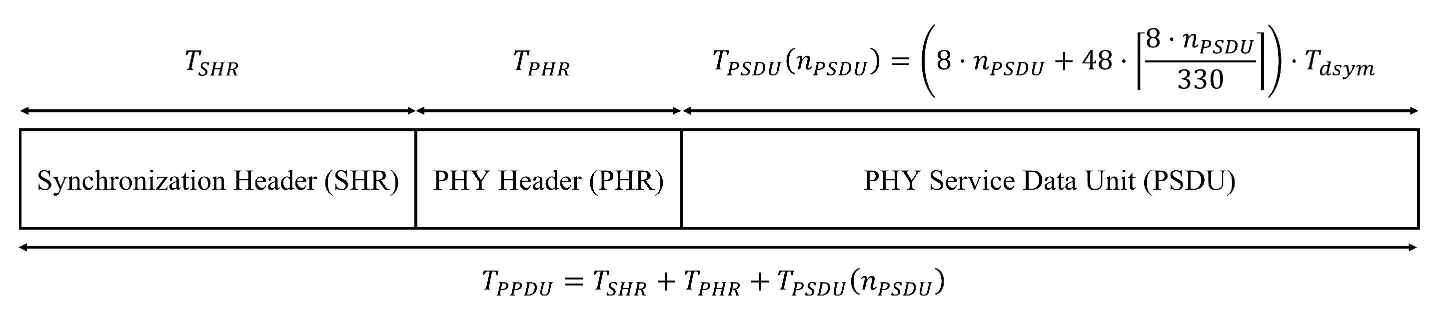
Transmission time of the Synchronization Header (SHR) ( T S H R )135.13 us
Transmission time of the PHY Header (PHR) ( T P H R )21.54 us
Data symbol duration ( T d s y m )128.21 ns
Table 3. Parameter setting for our routing simulation.
ParameterValue
Radio environmentUDGM with distance loss
Communication Range20 m
Transmission success ratio100%
Reception success ratio (%)90%
Network size75 m × 75 m × 75 m
Number of nodes125, 98 with void
Node deploymentgrid with (±5 m, ±5 m, ±5 m) randomness
P2P-RPL DAG lifetime16 s
P2P-DRO wait time1 s
P2P-RPL mode of operationNon-storing mode
Objective functionMRHOF
Routing metricETX
I m i n 2 5 ms, 2 6 ms
I m a x 2 22 ms
Redundancy constant (k)1 (except when I = I m i n )
Transmitter electronics ( E T X e l e c )33.97 nJ/bit
Transmitter amplifier ( ϵ a m p )6 pJ/bit/ m 2
Receiver electronics ( E R X e l e c )14.56 nJ/bit
Publisher’s Note: MDPI stays neutral with regard to jurisdictional claims in published maps and institutional affiliations.

