Article

Flux Intensifying Feature of Permanent Magnet Assisted Synchronous Reluctance Motor with High Torque Density

1
Department of Electrical Engineering, National Cheng Kung University, Tainan 701, Taiwan
2
Faculty of Electrical and Electronic Engineering, The University of Danang—University of Technology and Education, Danang 550000, Vietnam
3
Graduate School of Engineering, Toyota Technological Institute, Nagoya City 468-8511, Japan
*
Authors to whom correspondence should be addressed.
Electronics 2022, 11(3), 397; https://doi.org/10.3390/electronics11030397
Submission received: 29 December 2021 / Revised: 20 January 2022 / Accepted: 24 January 2022 / Published: 28 January 2022

Abstract

:
This paper investigates the flux intensifying (FI) feature of permanent magnet assisted synchronous reluctance motor (PMa-SynRM) in order to achieve high torque density with a small amount of permanent magnet (PM). This motor is thus denoted “FI-PMa-SynRM”. The performance of the developed FI-PMa-SynRM is compared with that of two other counterparts, i.e., an inset surface permanent magnet synchronous motor (SPMSM) and a synchronous reluctance motor (SynRM) to highlight the strengths of the FI-PMa-SynRM. In addition, an analysis on partial demagnetization and torque density of the developed FI-PMa-SynRM is conducted to demonstrate its advantages. The finite element method (FEM) is employed for the analysis in terms of flux linkage and inductances so that the effectiveness of the FI characteristics is validated. The analysis shows that a high torque density (24.79 Nm/L or even greater) can be achieved with a small amount of PM (0.72% motor volume). The ability of anti-demagnetization is also fulfilled. Furthermore, experimental results are provided to validate the analysis findings.

1. Introduction

Permanent magnet (PM) synchronous motor (PMSM) [1,2] and PM assisted synchronous reluctance motor (PMa-SynRM) [3,4] are currently interesting options in many applications such as electric vehicles (EVs) for their high efficiency and high torque/power densities. They can be efficiently driven by traction inverters used in EVs. However, because of the high cost of rare-earth PM, the objective to achieve high torque density by minimizing rare-earth materials and acceptable anti-demagnetization ability has been a critical concern. Many types of motors have been studied for this purpose [5,6,7,8,9,10]. Kim et al. [5] compared interior PMSMs with different PM shapes and dimensions to evaluate torque density. The factors of high torque density and low torque ripple were both considered by using embedded sinusoidal plus third harmonic shaped surface PM [6]. Multi-phases PM motors, e.g., a six-phase interior PMSM (IPMSM) [7] and a nine-phase consequent pole PMSM [8] were proposed with higher torque density compared to three-phase PM motors. Barcaro et al. [9] optimized PM volume for two PMa-SynRMs (i.e., one with rare-earth PM and the other with ferrite PM) to achieve a torque per stack length of 40 Nm/m and 15 Nm/m for low and high speed, respectively. Bonthu et al. [10] proposed and compared external-rotor PMa-SynRMs between rare-earth-free and rare-earth cases to satisfy the high torque and power density requirements. Moreover, a summary comparing the torque densities of some developed motors was shown and discussed in [11]. In this paper, a brief survey of some motor models in terms of volumetric torque density and PM-to-motor-volume ratio is presented in Appendix A for reference.
On the other hand, the irreversible demagnetization of PM in PMSM and PMa-SynRM has been a specific concern owing to the flux weakening/weakened (FW) feature of these motors [12,13,14,15,16,17]. Jeong and Hur compared PM demagnetization between two hybrid PMSMs with rare-earth and ferrite PMs [12]. Kim et al. analyzed partial PM demagnetization in PMSM [13]. The effect of concentrated and distributed windings on anti-demagnetization ability in rare-earth-less PMa-SynRM [14] and PM demagnetization on a wide speed range of PMa-SynRM [15] was investigated and evaluated. Bianchi and Mahmoud [16] presented an analytical approach to design PMa-SynRMs toward enhancement of anti-demagnetization ability. In addition, the demagnetization fault indexes of PMSM were overviewed [17]. As a potential option, the flux intensifying (FI) rotor configuration has been of recent interest as an alternative to conventional PMSMs which usually adopt the FW feature. This implies that the conventional PMSMs (mostly interior PMSMs) can possibly be transformed to FI-PMSMs with various PM shapes (e.g., flat PM shape [18,19], curved PM shape [20], and spoke type PM [21]) and with an equal or slightly lower amount of PM needed for better anti-demagnetization ability.
Generally, most of the above studies were carried out on motors with a large amount of rare-earth PM for obtaining high torque and good anti-demagnetization. To achieve a relatively high torque density by employing a small rare-earth PM amount or non-rare-earth PM and avoiding irreversible demagnetization are not easy tasks. To decrease the amount of the rare-earth PM, the FI configuration was attempted on a motor that is essentially a reluctance motor and this leads to the creation of the FI-PMa-SynRM [22]. This configuration (PM placed along d-axis) differs from common PMa-SynRM (PM placed along q-axis) so that PM flux linkage is intensified by part of the armature flux linkage. However, this previous work [22] mainly concentered on enchanting torque characteristics by optimizing flux barrier (FB) dimensions and the relative position between FB and PM. Moreover, the individual impact of FB and PM on motor performance (in particular, the ability to achieve high torque density) was not considered.
Therefore, this paper seeks for a new approach with a logical methodology, e.g., by comparing the difference between the developed FI-PMa-SynRM and its two counterparts (an inset surface PMSM (SPMSM) model and a SynRM model) to highlight the strength of the FI-PMa-SynRM. Then, further analysis of partial demagnetization is conducted to make sure of a safe operation of PM with sufficient anti-demagnetization ability. The torque density of the FI-PMa-SynRM is investigated and compared with another motor, aiming at demonstrating the substantial improvement of torque density with a small amount of PM by applying the FI feature. The prospective application of the designed FI-PMa-SynRM can be EV or hybrid EV traction motors excited by high-efficiency power electronics converters/inverters, that are controlled by electronic control units in vehicles.
The remaining parts of this manuscript are organized as follows. The investigated motor models and the concept of torque production are discussed in Section 2. After that, the performance difference and the effect of PM and FBs are analyzed and explained in Section 3. The detailed analysis for the developed motor model is represented in Section 4, followed by the experimental studies and related discussions in Section 5. Finally, the conclusion is concisely shown in Section 6.

2. Investigated Models and Concept of Torque Production and Improvement

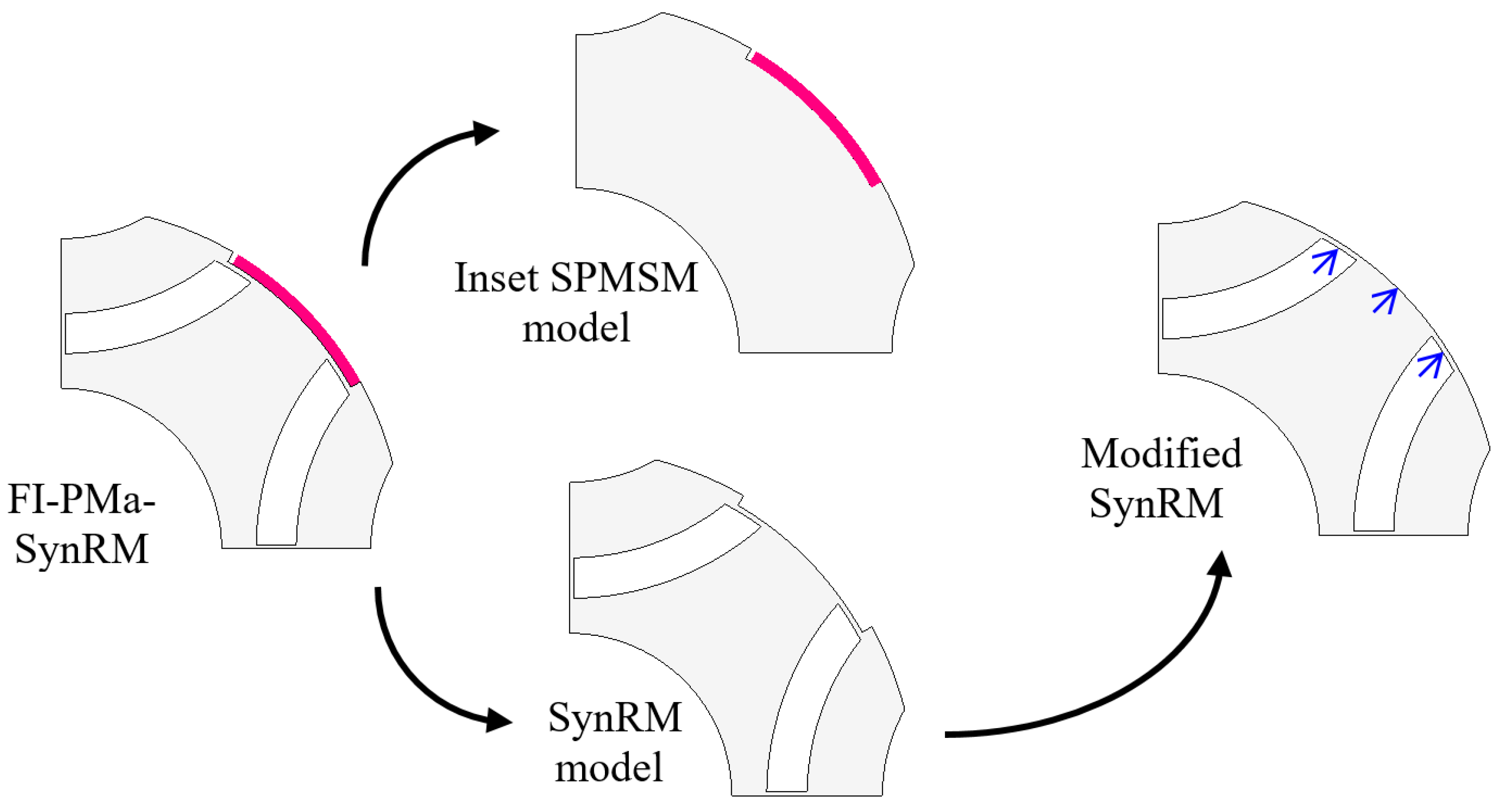
2.1. Investigated Models

From the viewpoint of motor construction, rotors of conventional PMa-SynRMs are constructed by adding PM to the rotors of SynRM [15,23,24,25]. For a recently proposed FI-PMSM, its rotor can be made by adding FBs on the q-axis of an IPMSM rotor [18,20]. These rotors all have PMs embedded inside the core, so it is difficult to evaluate the individual impact of PMs and FBs on motor characteristics. It is worth noting that both FBs and PMs have a great influence on the performance and characteristics of synchronous machines regardless of PM-based or reluctance-based machines [26].
Conversely, the developed FI-PMa-SynRM [22] employs the surface-inset PM layout to minimize the amount of PM used. This rotor configuration can be considered as the suitable combination of a SynRM with multiple FBs and a surface PMSM (SPMSM) due to the structural independence between PMs and main FBs (i.e., interior FB) [22]. Therefore, the roles of FB and PM can be individually assessed, and their individual contributions can be easily separately evaluated. In this paper, the two counterpart models are intentionally constructed with the same rotor shapes for easy and direct comparison. The first one is an Inset SPMSM model (only eliminating interior FBs as compared to the developed FI-PMa-SynRM) that represents the flux weakened motor, while the second one is a SynRM model (only removing PMs based on the FI-PMa-SynRM) with only reluctance torque, as indicated in Figure 1. The specifications of the investigated models are given in Table 1.

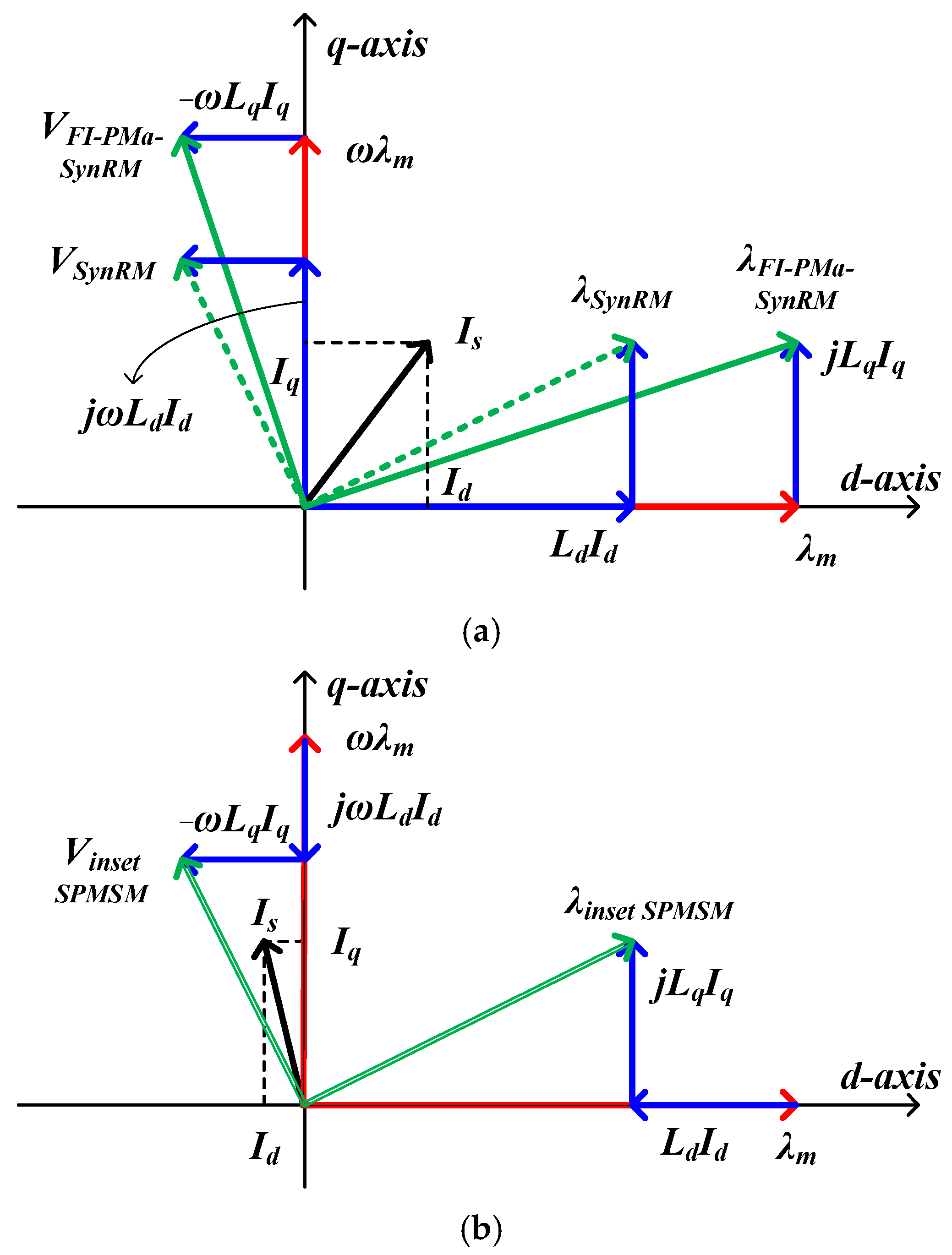
2.2. Concept of Torque Production and Improvement

Figure 2 represents the phasor diagrams of the FI-PMa-SynRM, Inset SPMSM, and SynRM, where it is assumed that the FI-PMa-SynRM and SynRM possess the same inductances and current vectors. We can see that the only flux linkage of the SynRM is the armature one, while those of the FI-PMa-SynRM and Inset SPMSM have PM parts, i.e., PM flux linkage (λm). However, the correlation between the PM and armature flux linkages in these two motors with PM is opposite. The PM flux linkage lies against the part of armature flux linkage on the d-axis for the Inset SPMSM and in the same direction for the FI-PMa-SynRM. The “FI” feature illustrated in Figure 2a enhances the anti-demagnetization ability. In contrast, the Inset SPMSM in Figure 2b is an FW motor, as the IPMSM and PMa-SynRM [26].
The torque equations for these three types of motors are discussed as follows. For the SynRM without embedded PM, the average torque can be expressed as:
T = 3 2 p ( L d I d I q L q I q I d ) = 3 2 p ( L d L q ) I d I q
where subscripts d and q represent the d- and q-axis respectively, Ld and Lq are the inductances, Id and Iq are the motor currents, and p is the number of pole pairs.
For the FI-PMa-SynRM and Inset SPMSM with PM flux linkage, their average torque can be determined by
T = 3 2 p [ ( λ m + L d I d ) I q L q I d I q ] = 3 2 p [ λ m I q + ( L d L q ) I d I q ]
Theoretically, the Inset SPMSM (an FW motor) has the current vector that is located in the second quadrant for maximum torque per ampere (MTPA) operation with a positive current phase advance angle. In contrast, the FI-PMa-SynRM has the current vector that is located in the first quadrant for MTPA or with a negative current phase advance angle [26]. Hence, despite the similar torque formulation, the electromagnetic mechanisms of the FI-PMa-SynRM and Inset SPMSM are different. Furthermore, additional torque components can be gained with the presence of PM flux linkage in the two types of motors. Nevertheless, the difference in having interior FBs between the FI-PMa-SynRM and Inset SPMSM will bring about the difference in torque production. The difference in inductances and saliency of these motors should also be considered. All these will be discussed in the next section.

3. Difference of Performance and Effect of Permanent Magnet and Flux Barriers
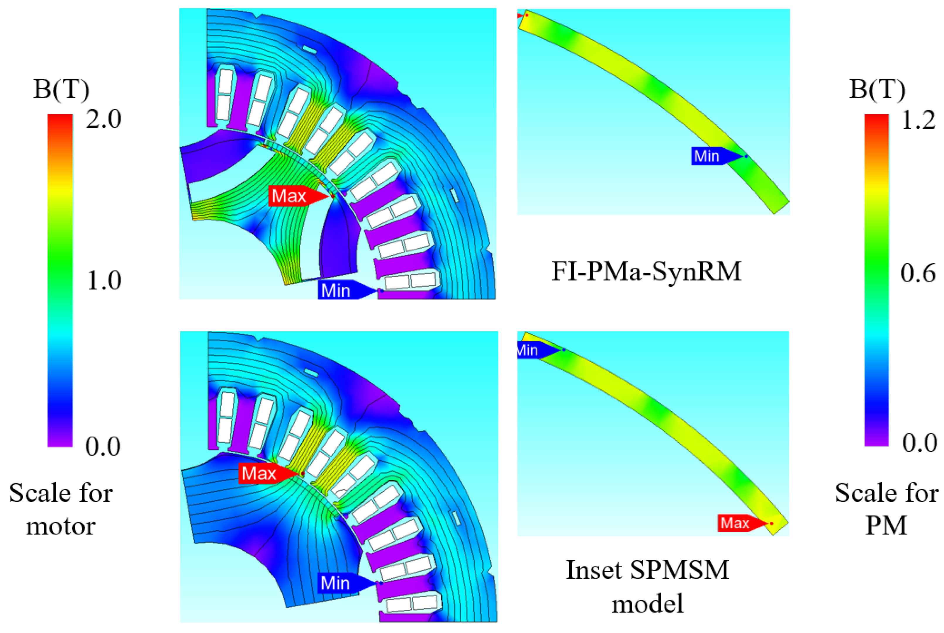
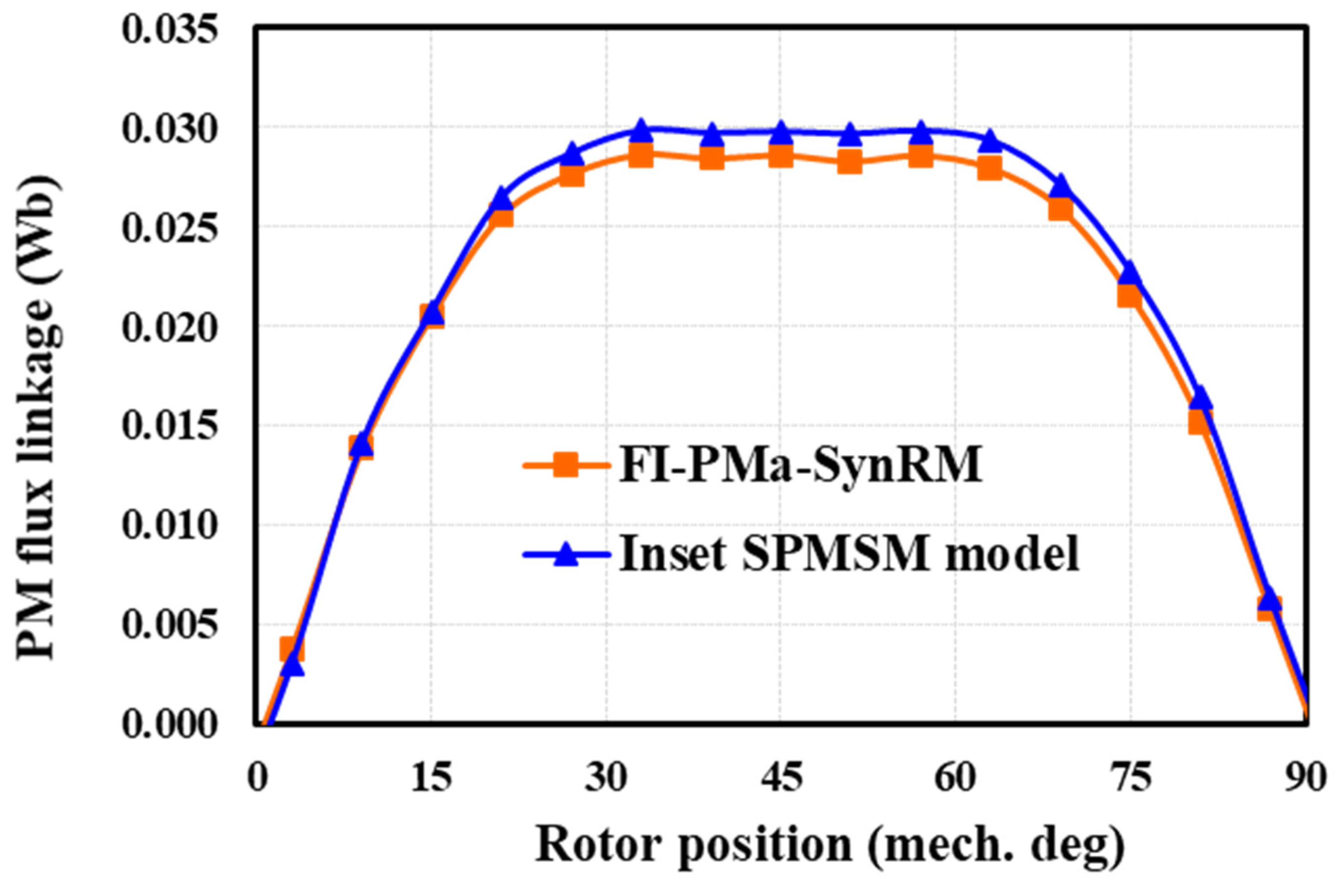
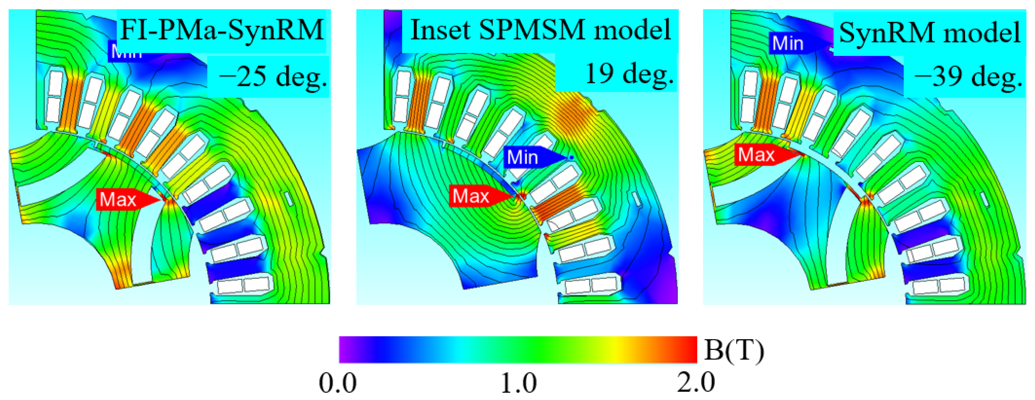
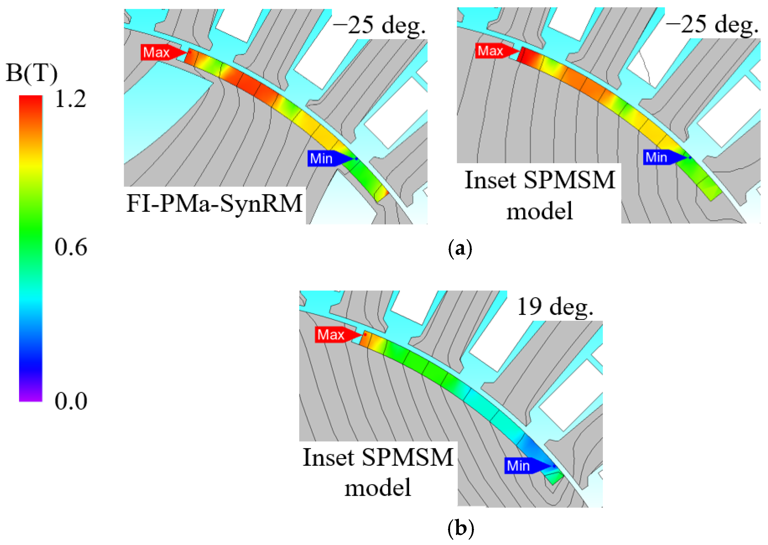
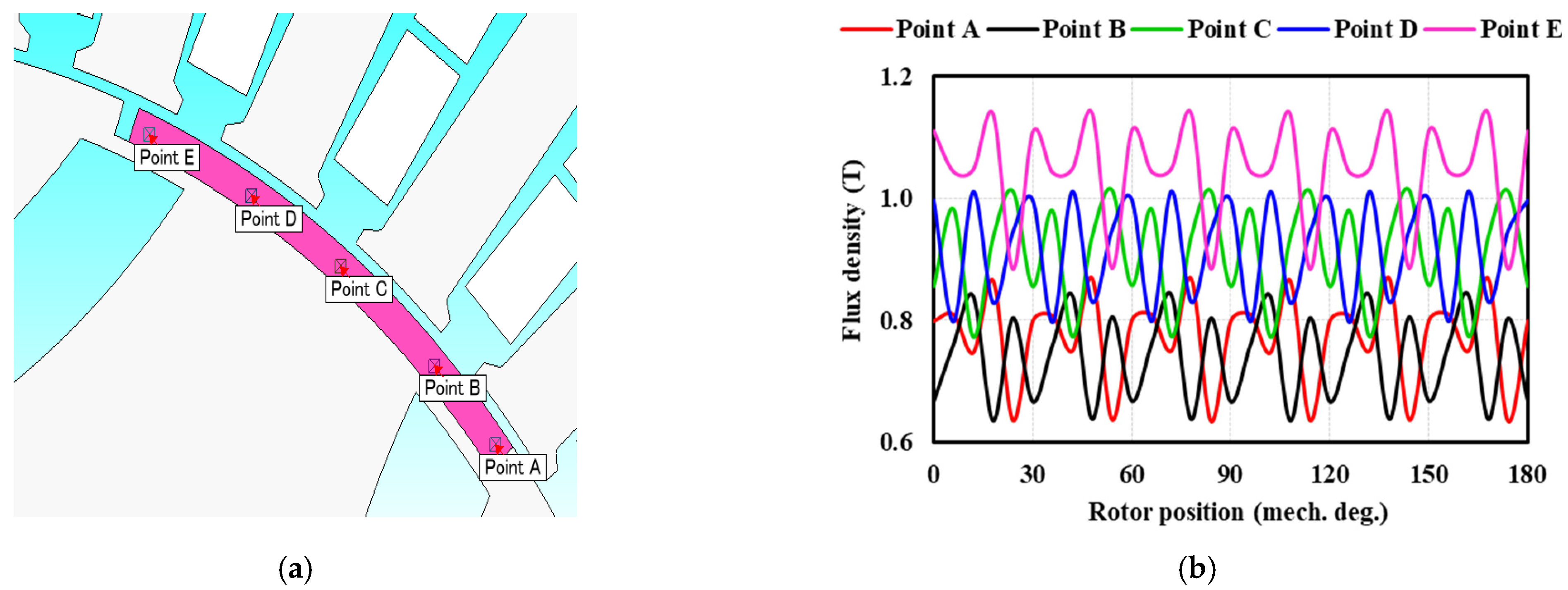
In this section, individual and coordinative effects of PM and FBs on the performance of the developed FI-PMa-SynRM are investigated by comparing these factors to those of its counterparts using the finite element method (FEM) in the JMAG package. The FEM mesh details of all the investigated models are provided in Appendix B.

3.1. Magnetic Field

The difference between these motor models is closely related to the distribution of magnetic fields. The no-load condition is first considered where the flux lines and flux densities are illustrated in Figure 3, where the FI-PMa-SynRM and Inset SPMSM model are considered. As presented in this figure, for the FI-PMa-SynRM, the flux density focuses on the region between two adjacent interior FBs, while for the Inset SPMSM model, the flux density focuses on the PMs. On the other hand, Figure 4 describes the comparison of the PM flux linkage of these models. We can see that the PM flux linkage of the Inset SPMSM is slightly higher than that of the FI-PMa-SynRM. These indicate that the FBs on the rotor of the FI-PMa-SynRM affect flux linkage generated by the PM and can be used to regulate flux density distributions of motors. Note that the no-load analysis can provide an overview of the impact of FBs while the motor performance can be fully studied in the presence of excitation current.
Then, Figure 5 shows the motor flux densities and distributions in the MTPA operations for the target synchronous motor models. Note that the FI-PMa-SynRM and SynRM operate with negative current phase advance while the SynRM has a greater phase advance (i.e., −39 and −25 degrees for the SynRM and FI-PMa-SynRM, respectively). This corresponds to the phasor diagrams presented in Figure 2. It can also be seen in Figure 5 that the flux density in the region between two adjacent interior FBs of the SynRM model is much smaller than that of the FI-PMa-SynRM. This can be understood due to the presence of PM where the PM greatly affects the magnetic distribution of these rotor layouts and plays a significant role in the operation of the FI-PMa-SynRM. In contrast, the Inset SPMSM operates with the positive current phase advance (i.e., 19 degrees), and the flux density distribution is much better than that in the no-load condition.
Finally, to describe the difference in the distribution of magnetic field between the FI motor (i.e., FI-PMa-SynRM) and the FW motor (i.e., Inset SPMSM model), the flux densities in PMs (representing the PM operating points) of the FI-PMa-SynRM and the Inset PMSM model at a current phase advance of −25 degrees based on MTPA control are shown in Figure 6a. The negative current phase advances indicate that these motor models are intentionally operated in the FI model. As can be seen, the overall flux densities in the PM seem to increase with applied current although part of the PMs may still suffer lower operating points. However, when the Inset SPMSM model operates in the MTPA condition, a positive current phase advance (19 degrees) is required, and the PM operating points are much lower due to flux weakening, as presented in Figure 6b. On the other hand, the lower PM operation points in the FI mode locate near air. For example, for the Inset SPMSM model, low PM operating points occur near the stator slots, while for the developed FI-PMa-SynRM, these are near stator slots and the end of FBs. This implies that lower operating points in partial PM are an inherent problem of surface PM motors, which will be considered in more detail in Section 4.

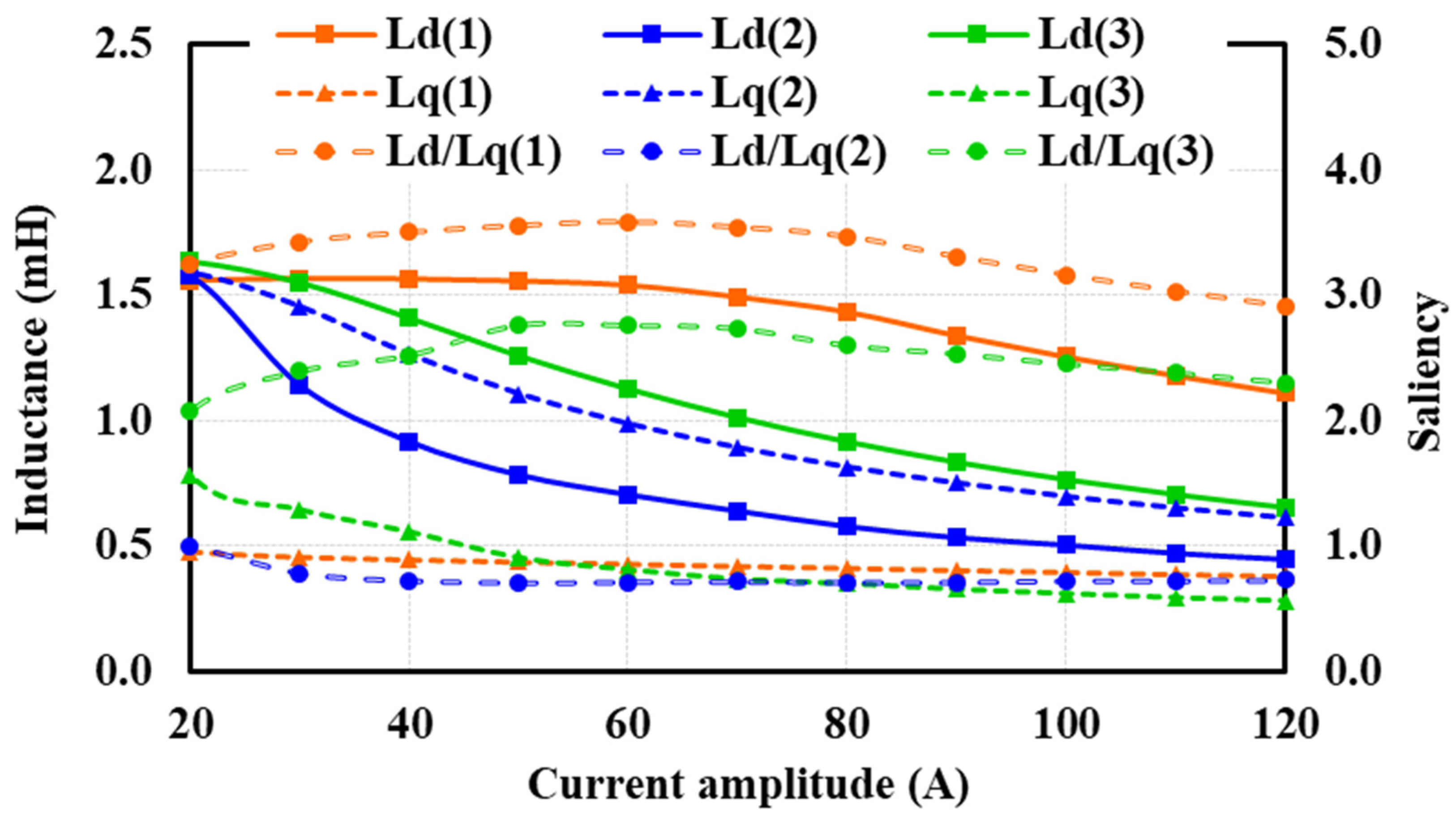
3.2. Inductance Variation

The simulation for inductance variation against current amplitude with current applied on the d-axis is shown in Figure 7. It can be seen that the inductances of the Inset SPMSM model (indicated by blue curves), Ld is slightly lower than Lq and they both decrease when the current magnitude increase so that the saliency is slightly lower than 1. This could be due to the fact that the added surface-mounted PM on d-axis may decrease Ld and thus bring Ld and Lq closer for conventional synchronous machines. For inductances of both the FI-PMa-SynRM and SynRM (indicated by orange and green curves, respectively), Ld is higher than Lq so that the saliency ratio, i.e., Ld/Lq of these models is higher than 1. On the other hand, it can be found that the trends of inductances (including Ld and Lq) of the FI-PMa-SynRM and the Inset SPMSM are quite different. Nevertheless, for the comparison between the FI-PMa-SynRM and the SynRM, their Lq is equivalent but Ld of the SynRM is rapidly reduced with the current while that of the FI-PMa-SynRM maintains. This indicates that the appearance of FBs greatly changes the properties of inductances while the appearance of PM mainly affects the d-axis inductance when comparing the developed FI-PMa-SynRM with its counterparts.

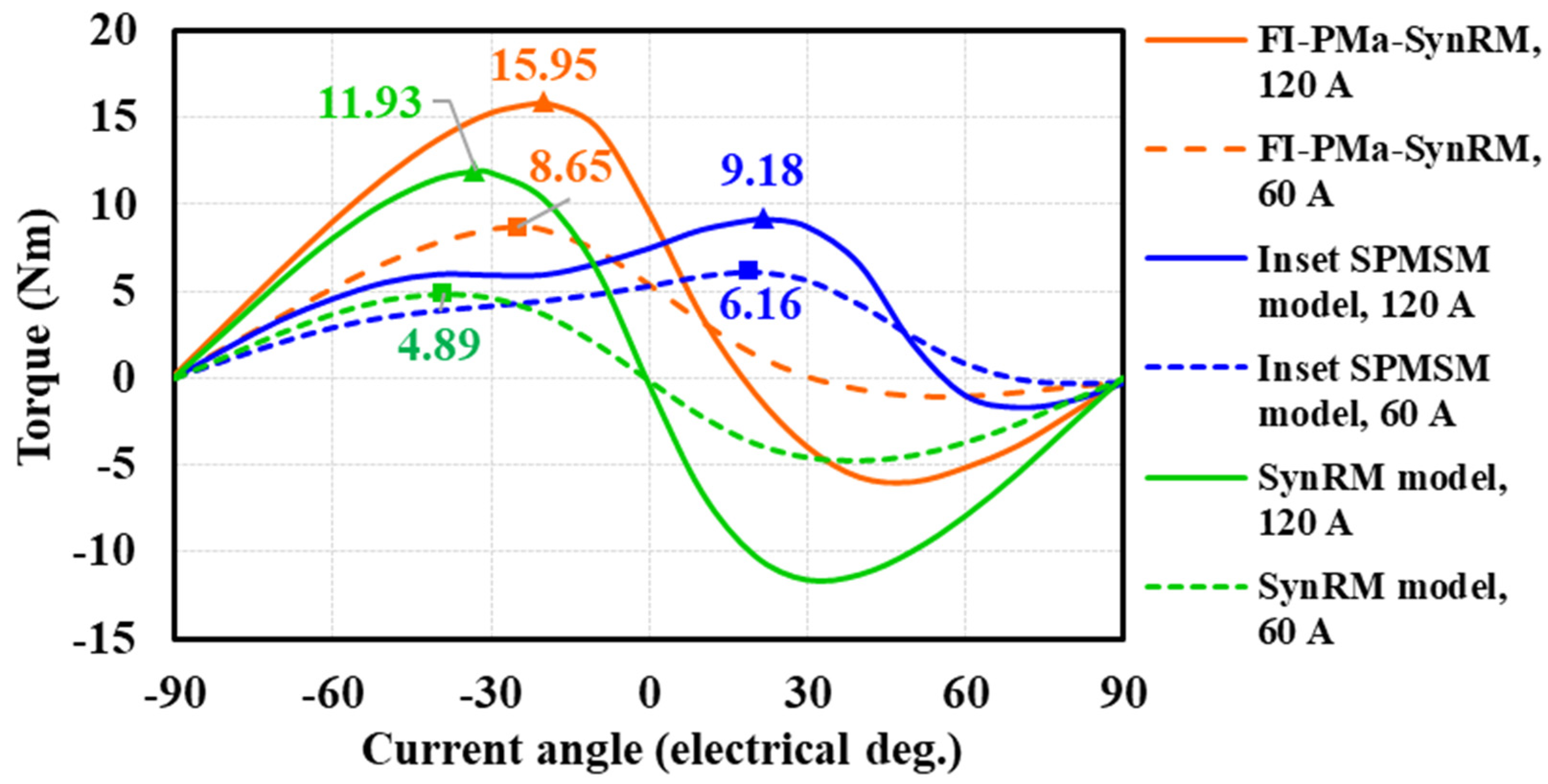
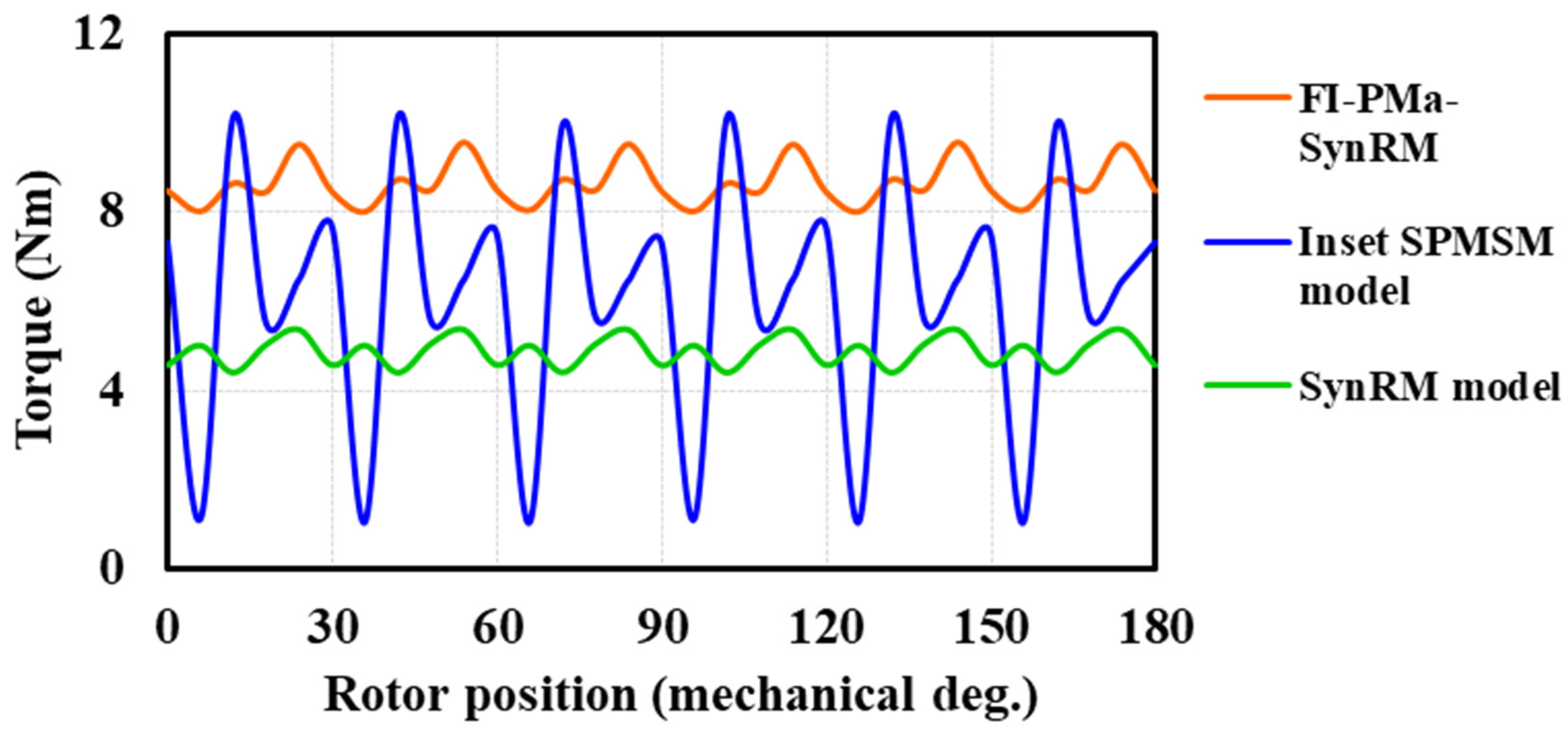
3.3. Torque Variation

Figure 8 shows the torque versus current angle/phase advance of these models at both the peak and rated current values (i.e., 120 A and 60 A, respectively). The MTPAs for the FI-PMa-SynRM and the SynRM are achieved with negative current phase advances and that for the Inset SPMSM model is with a positive phase advance. Moreover, with an added PM amount of just 0.72% of the motor active volume, the FI-PMa-SynRM has 1.77 and 1.34 times torque production of that of the SynRM at the rated and peak current, respectively. On the other hand, the FI-PMa-SynRM produces 1.4 and 1.73 times torque to that of the Inset SPMSM at the rated and peak currents, respectively.
In addition, Figure 9 shows the torque versus rotor positions corresponding to the rated current of these models. As can be seen, the pulsations of torque of the FI-PMa-SynRM and the SynRM are much lower than that of the Inset SPMSM. This indicates that the interior FB plays an important role to mitigate torque pulsation for these models, which were deliberately used in a previous design [22]. On the other hand, the torque pulsation of the FI-PMa-SynRM seems slightly greater than that of the SynRM model. This reveals that the appearance of surface PM not only affects the average torque but also the torque pulsation of the developed FI-PMa-SynRM. This conforms to the characteristics of motors using surface PM [6].

3.4. Brief Summary

From the above analysis, it can be revealed that:
-
The appearance of FBs in the developed FI-PMa-SynRM helps PM be better secured and leads to the reversal of inductance properties (FI-PMa-SynRM vs Inset SPMSM model).
-
The appearance of PM in the developed FI-PMa-SynRM leads to an enhancement of the flux density in the cores and the significant change of d-axis inductance (FI-PMa-SynRM vs SynRM model).
-
The coordination of PM and FBs in the FI-PMa-SynRM helps it enhance the torque production compared to those of its counterparts with a small added PM amount.

4. Further Analysis of Developed Motor

In the above analysis, the Inset SPMSM is made intentionally without interior FBs and likewise, the SynRM is without PM and thus the individual impact of FBs and PMs on the developed motor can be evaluated. In this section, the advantages of the FI feature on the developed model will be further analyzed through the evaluation of the demagnetization issue and torque density capability.

4.1. Partial Demagnetization

Five observed points are selected along the PM span as described in Figure 10a, while the variation of flux density of these points is shown in Figure 10b. As can be seen, the flux density at points A and B is lower compared to those of others, which indicates that the PM region between points A and B would be more easily demagnetized. Besides, this region is near a FB and this conforms to the prediction of partial demagnetization problem in Section 3. However, it should be noted that these flux densities are not too low so that the irreversible demagnetization is unlikely to occur for a small PM dimension (only 1.5 mm thick). On the other hand, the advantage of this simple structure is such that alternative designs can be easily applied with minor modifications, e.g., using a thicker PM to fully avoid irreversible demagnetization for a similar design.

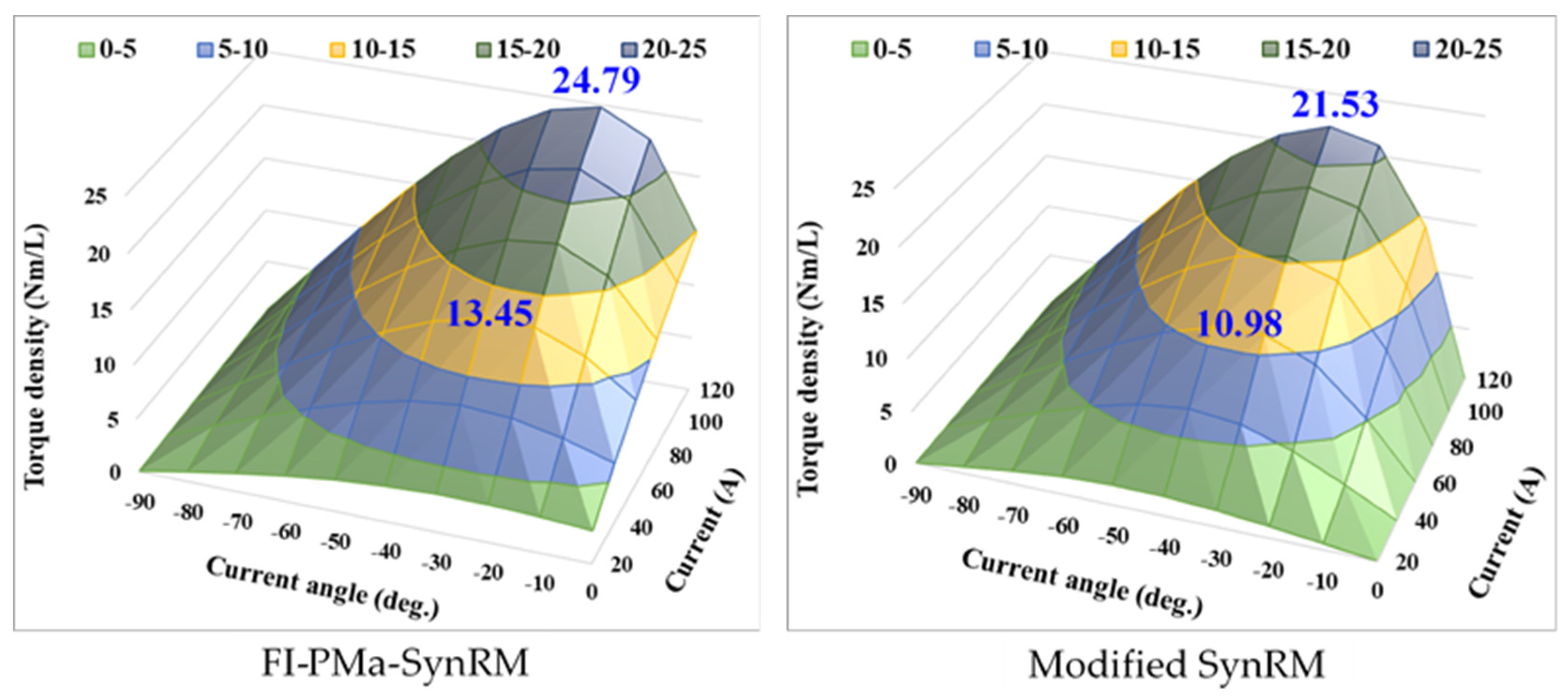
4.2. Torque Density Capability

As previously discussed, the models compared in Section 2 (i.e., the Inset SPMSM and SynRM models) are used to evaluate the role of FBs and PM in the developed FI-PMa-SynRM. Nevertheless, different motors may have dissimilar design considerations, e.g., the air-gap length of a SynRM could be smaller. To demonstrate the capability of achieving high torque density with only a small amount of PM, the developed FI-PMa-SynRM will be compared to another realistic model by extending the boundary of the rotor surface as well as the end of FB so that the air gap and rotor ribs are the same as those of the developed model. This model is called the Modified SynRM as also illustrated in Figure 1 (i.e., the right part), where the blue arrows indicate the boundary extension.
Figure 11 shows the comparison of torque density versus current amplitude and angle (from −90 to 0 degrees) between the FI-PMa-SynRM and the Modified SynRM. As can be seen, the FI-PMa-SynRM offers a better torque density. Moreover, the FI-PMa-SynRM has a much broader high torque density zone (above 20 Nm/L) for the given current magnitude and angle ranges. This can be explained by the fact that the FI-PMa-SynRM is capable of effectively combining reluctance torque and PM torque in comparison with other types of motors, with multiple FBs to gain high reluctance torque and a small amount of surface-inset PM for an extra portion of torque. Most importantly, since the PM in the FI-PMa-SynRM is not easily demagnetized, a higher current can be applied to gain even higher torque output. However, this will be limited by the magnetic saturation, heat dissipation, and possible partial PM demagnetization as mentioned above. As a result, this motor can achieve high torque density, i.e., 13.45 Nm/L and 24.79 Nm/L at the rated and peak conditions, respectively.

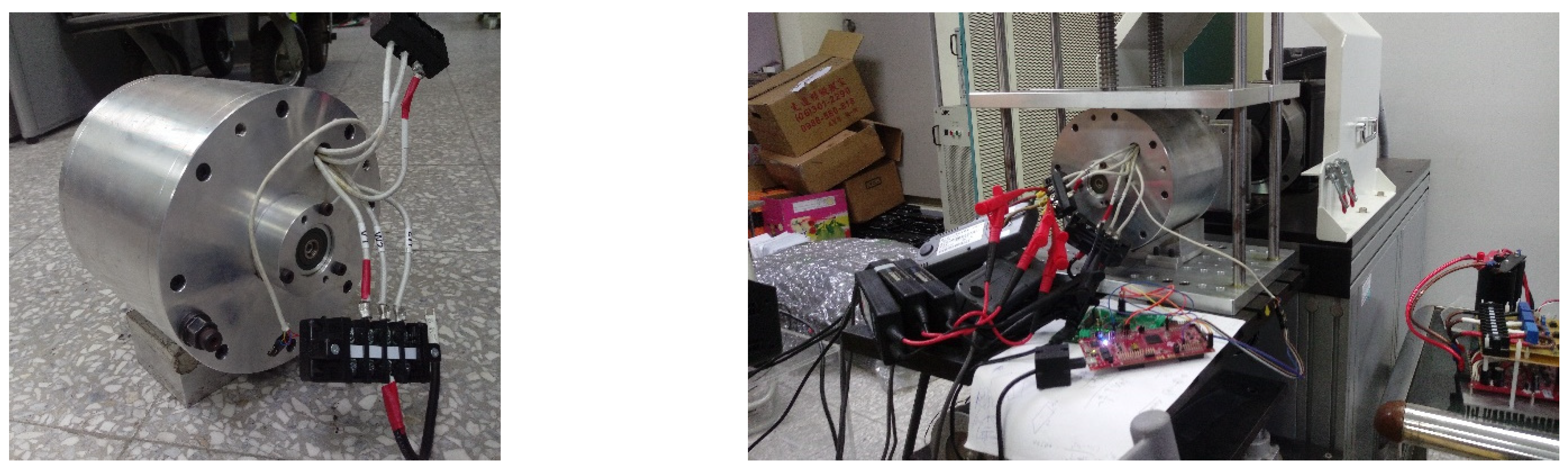
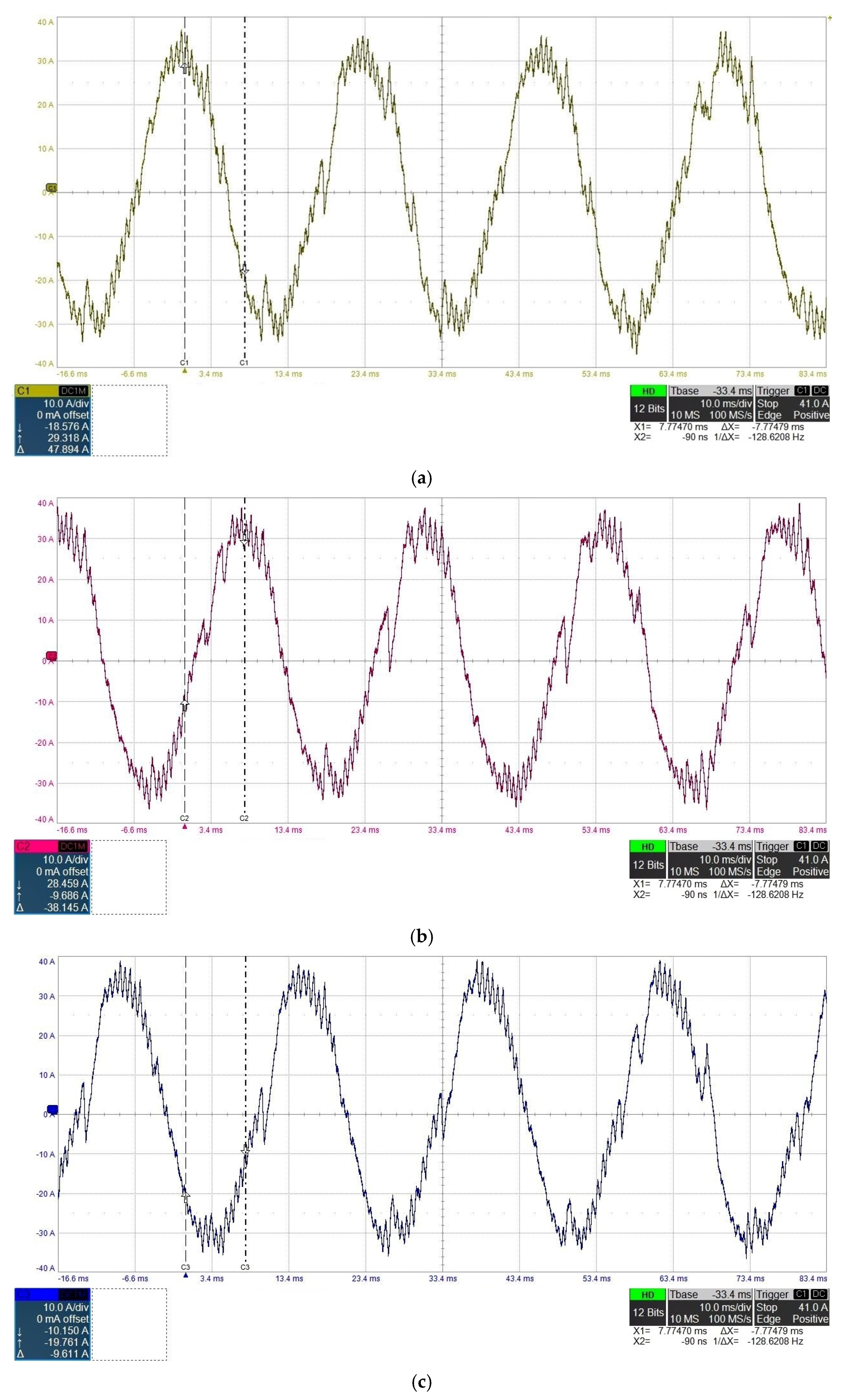
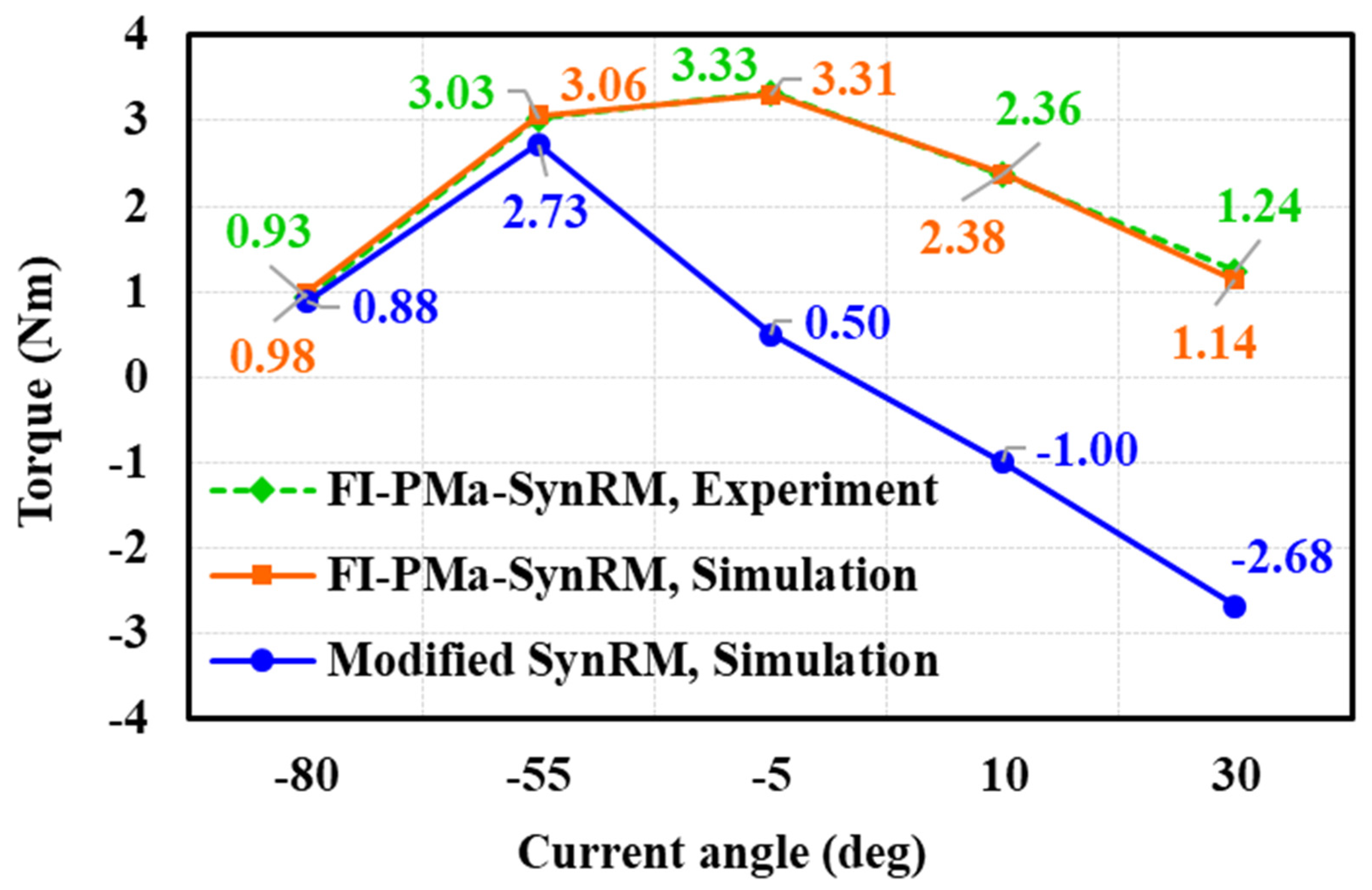
5. Experiment Results

The experimental setup for evaluation, measured current waveforms of the developed FI-PMa-SynRM prototype, current harmonics, and torque comparison are shown in Figure 12, Figure 13, Figure 14 and Figure 15, respectively. In Figure 14, the fundamental frequency is 42 Hz. Because of the limitation of the power source and measurement devices in our laboratories, the developed FI-PMa-SynRM is only measured up to 32.5 A, where the total harmonic distortion (THD) of the motor current is around 13.04%. The torque production of the developed FI-PMa-SynRM for the measurement and simulation are compared and presented in Figure 15. As can be seen, the two cases agree well. On the other hand, the simulation results of the modified SynRM are added to compare with the developed FI-PMa-SynRM. As depicted in Figure 15, with a small current angle (about −55 degrees), the torque production of the Modified SynRM is only slightly smaller than that of the FI-PMa-SynRM, while with a higher current angle, the torque of the Modified SynRM decreases very quickly. The torque of the Modified SynRM can become negative but that of FI-PMa-SynRM is still positive. These results also conform to the theory mentioned above.
In future research, to further evaluate the overall efficacy of the developed FI-PMa-SynRM, the core loss properties and efficiency under the excitation of power electronics inverters will be investigated in detail by simulation and experiment [27,28].

6. Conclusions

In this paper, a thorough investigation of the FI feature on PMa-SynRM (denoted FI-PMa-SynRM) to achieve a high torque density was shown. Firstly, through a comparison of the developed FI-PMa-SynRM with its two counterparts which were obtained simply by eliminating interior FB or PM, the role of these elements on the developed motor was studied. Secondly, the partial demagnetization of the developed motor was analyzed, and its torque density capability was investigated through a comparison with another realistic motor. It was found that adopting the FI configuration leads to the difference in the magnetic field patterns and current angle to achieve the MTPA operation. As a result, a high torque density was demonstrated to be achievable with only a small amount of PM while the ability to avoid PM irreversible demagnetization was validated by simulation and experimental results. These have illustrated the feasibility of applying the FI feature to PMa-SynRM. Moreover, the simple structure of the developed FI-PMa-SynRM can be treated as an interesting and helpful design reference.

Author Contributions

Conceptualization and methodology, M.-F.H. and D.-K.N.; software and investigation, D.-K.N. and N.G.M.T.; result analysis and evaluation, M.-F.H., D.-K.N. and N.G.M.T., writing—review and editing, M.-F.H., D.-K.N. and N.G.M.T. All authors have read and agreed to the published version of the manuscript.

Funding

This work was supported in part by The University of Danang—University of Technology and Education under Grant Number T2021-06-02, Ministry of Science and Technology of Taiwan under contract MOST 110-2221-E-006-184-MY2, and JSPS KAKENHI Grant Number 21K14182.

Acknowledgments

The authors would like to thank JSOL Corporation for supporting JMAG.

Conflicts of Interest

The authors declare no conflict of interest.

Nomenclature and Abbreviations

The following nomenclature and abbreviations are used in this paper:
dDirect axis
IdD-axis current
IqQ-axis current
LdD-axis stator inductance
LqQ-axis stator inductance
pNumber of pole pairs
qQuadrature axis
TTorque
VFI-PMa-SynRMVoltage of FI-PMa-SynRM
Vinset SPMSMVoltage of inset SPMSM
VSynRMVoltage of SynRM
λFI-PMa-SynRMFlux linkage of FI-PMa-SynRM
λinset SPMSMFlux linkage of inset SPMSM
λmPM flux linkage
λSynRMFlux linkage of SynRM
ωElectric angular speed
EVElectric vehicle
FBFlux barrier
FEMFinite element method
FIFlux intensifying
FI-PMa-SynRMFlux intensifying permanent magnet assisted synchronous reluctance motor
FI-PMSMFlux intensifying permanent magnet synchronous motor
FWFlux weakening/weakened
IPMSMInterior permanent magnet synchronous motor
MTPAMaximum torque per ampere
PMPermanent magnet
PMa-SynRMPermanent magnet assisted synchronous reluctance motor
PMSMPermanent magnet synchronous motor
SPMSMSurface permanent magnet synchronous motor
SynRMSynchronous reluctance motor
THDTotal harmonic distortion

Appendix A. Brief Information of Motor Models

A survey of the volumetric torque density and PM-to-motor-volume ratio is provided in Table A1. Note that the torque density of the individual motors would depend on the design, current, current density, thermal condition, and so forth; thus, the comparison in Table A1 is only used for reference but not an accurate indication of motor performance.
Table A1. Brief information of motor models.
ModelsVolumetric Torque Density (Nm/L)PM-to-Motor Volume Ratio (%)Peak Current Density (A/mm2)Anti-Demagnetization AbilityPrototype
FI-PMa-SynRM24.790.7215.35ValidatedDone
Model in [6]63.794.2226.87ValidatedNot yet
Model in [7]52.82N/A25.1N/ADone
Model in [10]14.914.32N/AValidatedDone

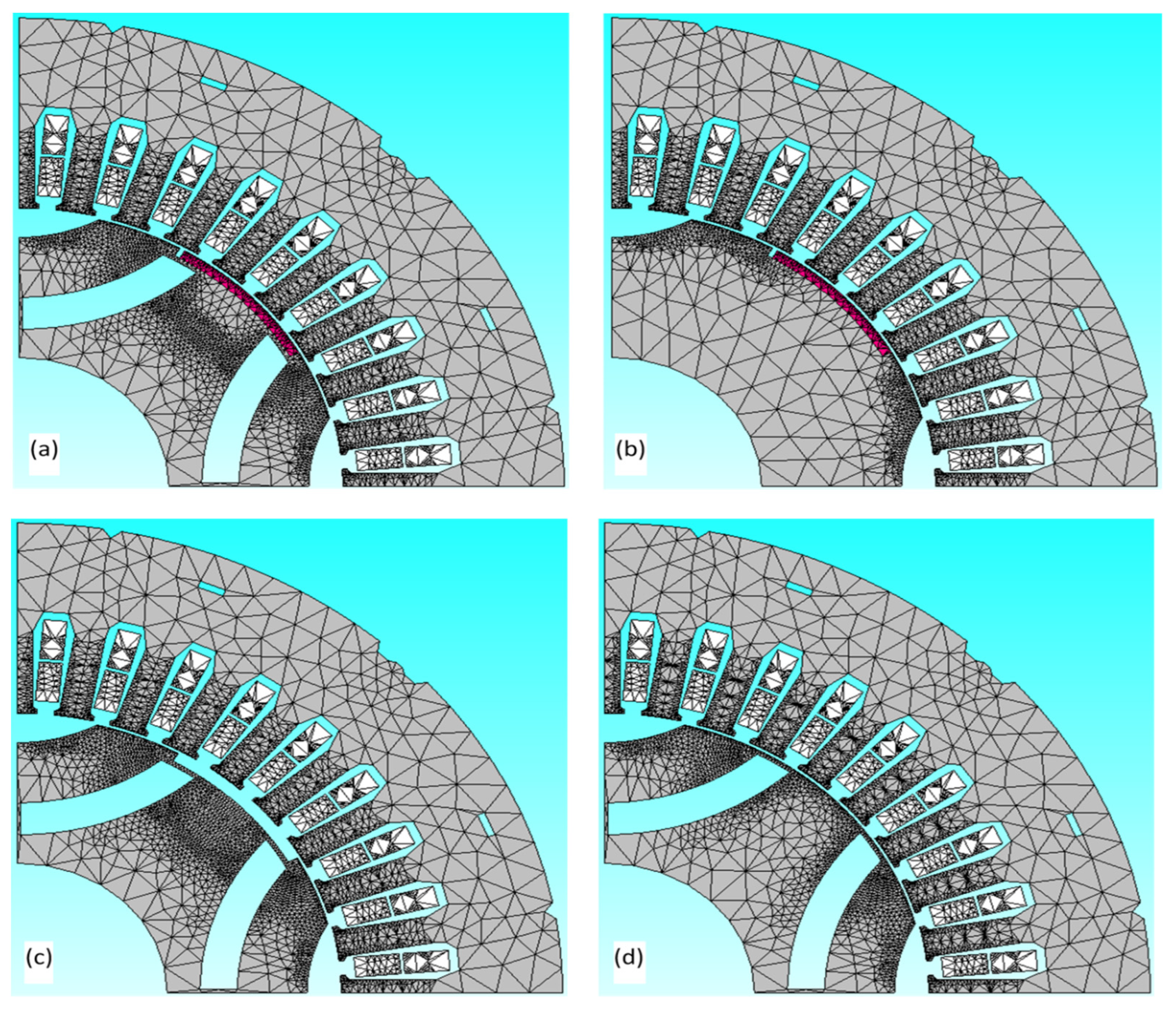
Appendix B. Finite Element Mesh Information

The finite element software package utilized in this paper is JMAG from JOSL Corporation. The finite element models of the considered motors are constructed through the standard meshing setup of JMAG. The detailed mesh information used in this study is described in Table A2, and the meshing for the four models is illustrated in Figure A1.
Table A2. Mesh information of considered four models.
Motor ModelsNumber of ElementsNumber of Nodes
FI-PMa-SynRM12,4676712
Inset SPMSM10,1475553
SynRM12,6156786
Modified SynRM11,8456396
Figure A1. Meshing illustration: (a) FI-PMa-SynRM; (b) Inset SPMSM model; (c) SynRM model; (d) Modified SynRM.
Electronics 11 00397 g0a1

References

  1. Kim, K.-C.; Lee, J.; Kim, H.J.; Koo, D.-H. Multiobjective Optimal Design for Interior Permanent Magnet Synchronous Motor. IEEE Trans. Magn. 2009, 45, 1780–1783. [Google Scholar] [CrossRef]
  2. Zhang, Y.; Cao, W.; McLoone, S.; Morrow, J. Design and Flux-Weakening Control of an Interior Permanent Magnet Synchronous Motor for Electric Vehicles. IEEE Trans. Appl. Supercond. 2016, 26, 0606906. [Google Scholar] [CrossRef] [Green Version]
  3. Bianchi, N.; Bolognani, S.; Carraro, E.; Castiello, M.; Fornasiero, E. Electric Vehicle Traction Based on Synchronous Reluctance Motors. IEEE Trans. Ind. Appl. 2016, 52, 4762–4769. [Google Scholar] [CrossRef]
  4. Son, J.-C.; Ahn, J.-M.; Lim, J.; Lim, D.-K. Optimal Design of PMa-SynRM for Electric Vehicles Exploiting Adaptive-Sampling Kriging Algorithm. IEEE Access 2021, 9, 41174–41183. [Google Scholar] [CrossRef]
  5. Kim, M.-J.; Cho, S.-Y.; Lee, K.-D.; Lee, J.-J.; Han, J.-H.; Jeong, T.-C.; Kim, W.-H.; Koo, D.-H.; Lee, J. Torque Density Elevation in Concentrated Winding Interior PM Synchronous Motor With Minimized Magnet Volume. IEEE Trans. Magn. 2013, 49, 3334–3337. [Google Scholar] [CrossRef]
  6. Du, Z.S.; Lipo, T.A. High Torque Density and Low Torque Ripple Shaped-Magnet Machines Using Sinusoidal Plus Third Harmonic Shaped Magnets. IEEE Trans. Ind. Appl. 2019, 55, 2601–2610. [Google Scholar] [CrossRef]
  7. Patel, V.I.; Wang, J.; Nugraha, D.T.; Vuletic, R.; Tousen, J. Enhanced Availability of Drivetrain Through Novel Multiphase Permanent-Magnet Machine Drive. IEEE Trans. Ind. Electron. 2016, 63, 469–480. [Google Scholar] [CrossRef]
  8. Onsal, M.; Demir, Y.; Aydin, M. A New Nine-Phase Permanent Magnet Synchronous Motor with Consequent Pole Rotor for High-Power Traction Applications. IEEE Trans. Magn. 2017, 53, 8700606. [Google Scholar] [CrossRef]
  9. Barcaro, M.; Bianchi, N.; Magnussen, F. Permanent-Magnet Optimization in Permanent-Magnet-Assisted Synchronous Reluctance Motor for a Wide Constant-Power Speed Range. IEEE Trans. Ind. Electron. 2012, 59, 2495–2502. [Google Scholar] [CrossRef]
  10. Bonthu, S.S.R.; Arafat, A.; Choi, S. Comparisons of Rare-Earth and Rare-Earth-Free External Rotor Permanent Magnet Assisted Synchronous Reluctance Motors. IEEE Trans. Ind. Electron. 2017, 64, 9729–9738. [Google Scholar] [CrossRef]
  11. Ngo, D.-K.; Hsieh, M.-F. Performance Analysis of Synchronous Reluctance Motor with Limited Amount of Permanent Magnet. Energies 2019, 12, 3504. [Google Scholar] [CrossRef] [Green Version]
  12. Jeong, C.-L.; Hur, J. Optimization Design of PMSM with Hybrid-Type Permanent Magnet Considering Irreversible Demagnetization. IEEE Trans. Magn. 2017, 53, 8110904. [Google Scholar] [CrossRef]
  13. Kim, K.-C.; Lim, S.-B.; Koo, D.-H.; Lee, J. The Shape Design of Permanent Magnet for Permanent Magnet Synchronous Motor Considering Partial Demagnetization. IEEE Trans. Magn. 2006, 42, 3485–3487. [Google Scholar] [CrossRef]
  14. Huang, H.; Hu, Y.-S.; Xiao, Y.; Lyu, H. Research of Parameters and Antidemagnetization of Rare-Earth-Less Permanent Magnet-Assisted Synchronous Reluctance Motor. IEEE Trans. Magn. 2015, 51, 8112504. [Google Scholar] [CrossRef]
  15. Park, G.-J.; Kim, J.-S.; Son, B.; Jung, S.-Y. Optimal Design of PMa-synRM for an Electric Propulsion System Considering Wide Operation Range and Demagnetization. IEEE Trans. Appl. Supercond. 2018, 28, 5205804. [Google Scholar] [CrossRef]
  16. Bianchi, N.; Mahmoud, H. An Analytical Approach to Design the PM in PMAREL Motors Robust Toward the Demagnetization. IEEE Trans. Energy Convers. 2016, 31, 800–809. [Google Scholar] [CrossRef]
  17. Faiz, J.; Nejadi-Koti, H. Demagnetization Fault Indexes in Permanent Magnet Synchronous Motors—An Overview. IEEE Trans. Magn. 2016, 52, 8201511. [Google Scholar] [CrossRef]
  18. Limsuwan, N.; Kato, T.; Akatsu, K.; Lorenz, R.D. Design and Evaluation of a Variable-Flux Flux-Intensifying Interior Permanent-Magnet Machine. IEEE Trans. Ind. Appl. 2014, 50, 1015–1024. [Google Scholar] [CrossRef]
  19. Prins, M.H.A.; Kamper, M.J. Design optimisation of field-intensified permanent magnet machine. In Proceedings of the 2014 International Conference on Electrical Machines (ICEM), Berlin, Germany, 2–5 September 2014; pp. 117–123. [Google Scholar] [CrossRef]
  20. Zhu, X.; Huang, J.; Quan, L.; Xiang, Z.; Shi, B. Comprehensive Sensitivity Analysis and Multiobjective Optimization Research of Permanent Magnet Flux-Intensifying Motors. IEEE Trans. Ind. Electron. 2019, 66, 2613–2627. [Google Scholar] [CrossRef]
  21. Chui, M.-T.; Chiang, J.-A.; Gaing, Z.-L.; Hsien, Y.-Y. Design of a novel flux-intensifying interior permanent-magnet motor for applying to refrigerant compressor. In Proceedings of the 2015 18th International Conference on Electrical Machines and Systems (ICEMS), Pattaya, Thailand, 25–28 October 2015; pp. 232–236. [Google Scholar] [CrossRef]
  22. Ngo, D.-K.; Hsieh, M.-F.; Huynh, T.A. Torque Enhancement for a Novel Flux Intensifying PMa-SynRM Using Surface-Inset Permanent Magnet. IEEE Trans. Magn. 2019, 55, 8106108. [Google Scholar] [CrossRef]
  23. Jung, D.-H.; Kwak, Y.; Lee, J.; Jin, C.-S. Study on the Optimal Design of PMa-SynRM Loading Ratio for Achievement of Ultrapremium Efficiency. IEEE Trans. Magn. 2017, 53, 8001904. [Google Scholar] [CrossRef]
  24. Liu, C.-T.; Luo, T.-Y.; Shih, P.-C.; Yen, S.-C.; Lin, H.-N.; Hsu, Y.-W.; Hwang, C.-C.; Lin, H.-N. On the Design and Construction Assessments of a Permanent-Magnet-Assisted Synchronous Reluctance Motor. IEEE Trans. Magn. 2017, 53, 2002104. [Google Scholar] [CrossRef]
  25. Xu, M.; Liu, G.; Chen, Q.; Ji, J.; Zhao, W. Torque Calculation of Stator Modular PMa-SynRM With Asymmetric Design for Electric Vehicles. IEEE Trans. Transp. Electrif. 2021, 7, 202–213. [Google Scholar] [CrossRef]
  26. Ngo, D.-K.; Hsieh, M.-F. Analysis of Flux Intensifying Effect on Synchronous Motors Applied to Electric Scooter. In Proceedings of the 2019 IEEE Vehicle Power and Propulsion Conference (VPPC), Hanoi, Vietnam, 14–17 October 2019; pp. 1–6. [Google Scholar] [CrossRef]
  27. Thao, N.G.M.; Zhong, S.; Fujisaki, K.; Iwamoto, F.; Kimura, T.; Yamada, T. Assessment of motor core loss, copper loss and magnetic flux density with PAM inverter under dissimilar excitation angles. IET Electr. Power Appl. 2020, 14, 622–637. [Google Scholar] [CrossRef]
  28. Thao, N.G.M.; Denis, N.; Wu, Y.; Odawara, S.; Fujisaki, K. Study of the Effect of Load Torque on the Iron Losses of Permanent Magnet Motors by using Finite Element Analysis. IEEJ J. Ind. Appl. 2019, 8, 522–531. [Google Scholar] [CrossRef] [Green Version]
Figure 1. Rotor layouts of investigated models.
Electronics 11 00397 g001
Figure 2. Phasor diagrams: (a) FI-PMa-SynRM and SynRM; (b) Inset SPMSM.
Electronics 11 00397 g002
Figure 3. Motor flux densities at no-load conditions. Upper part: FI-PMa-SynRM; lower part: Inset SPMSM.
Electronics 11 00397 g003
Figure 4. PM flux linkages.
Electronics 11 00397 g004
Figure 5. Motor flux densities at MTPA operation of motors. Left part: FI-PMa-SynRM; central part: Inset SPMSM; right part: SynRM.
Electronics 11 00397 g005
Figure 6. Compare PM flux densities distributions: (a) FI-PMa-SynRM and Inset SPMSM model at −25 degrees; (b) Inset SPMSM model at 19 degrees.
Electronics 11 00397 g006
Figure 7. Inductance and saliency vs current magnitude for FI-PMa-SynRM(1), Inset SPMSM model(2), and SynRM model(3).
Electronics 11 00397 g007
Figure 8. Torque productions vs current angle/phase advance.
Electronics 11 00397 g008
Figure 9. Torque vs. rotor positions.
Electronics 11 00397 g009
Figure 10. Demagnetization analysis: (a) Observed points; (b) Flux density variation of observed points at 105 °C.
Electronics 11 00397 g010
Figure 11. Comparison of torque density between FI-PMa-SynRM and Modified SynRM.
Electronics 11 00397 g011
Figure 12. Experimental setup for evaluation of developed FI-PMa-SynRM prototype.
Electronics 11 00397 g012
Figure 13. Measured current waveforms of developed FI-PMa-SynRM with the current of 32.5 A and angle of −55 degrees: (a) Phase U; (b) Phase V; (c) Phase W.
Electronics 11 00397 g013
Figure 14. Current harmonics of developed FI-PMa-SynRM.
Electronics 11 00397 g014
Figure 15. Comparison of measured torque and simulation results.
Electronics 11 00397 g015
Table 1. Specifications of Target Motors.
ParameterUnitValue
Outer radius of statormm80
Outer radius of rotormm47
Length of stackmm32
PM spanmm24
PM thicknessmm1.5
Motor volumeL0.6434
PM volumeL0.0046
PM/motor volume ratio%0.72
Publisher’s Note: MDPI stays neutral with regard to jurisdictional claims in published maps and institutional affiliations.

