
Speed Estimation Method of Linear Motor Extended Kalman Filter Based on Attenuation Memory

 , ,
, , 
Abstract
:1. Introduction
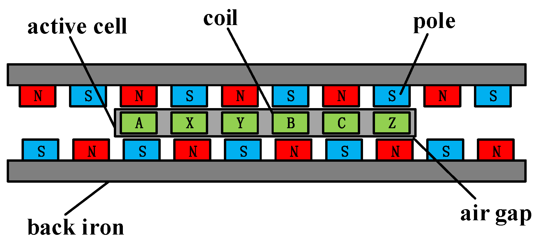
2. PMLSM Mathematical Model
3. Extended Kalman Filter
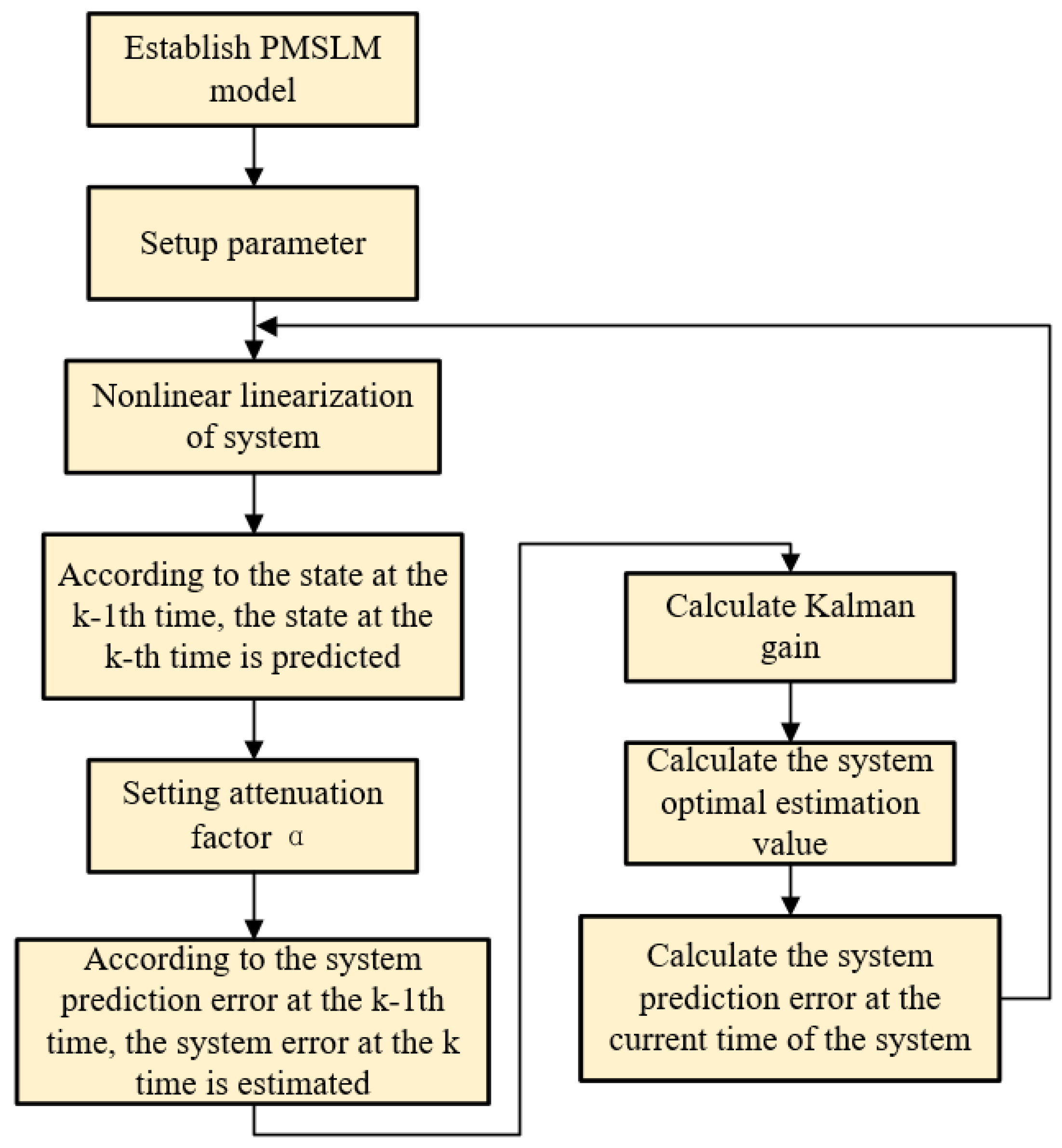
4. Attenuated Memory Extended Kalman Filter Algorithm
4.1. Filtering Algorithm
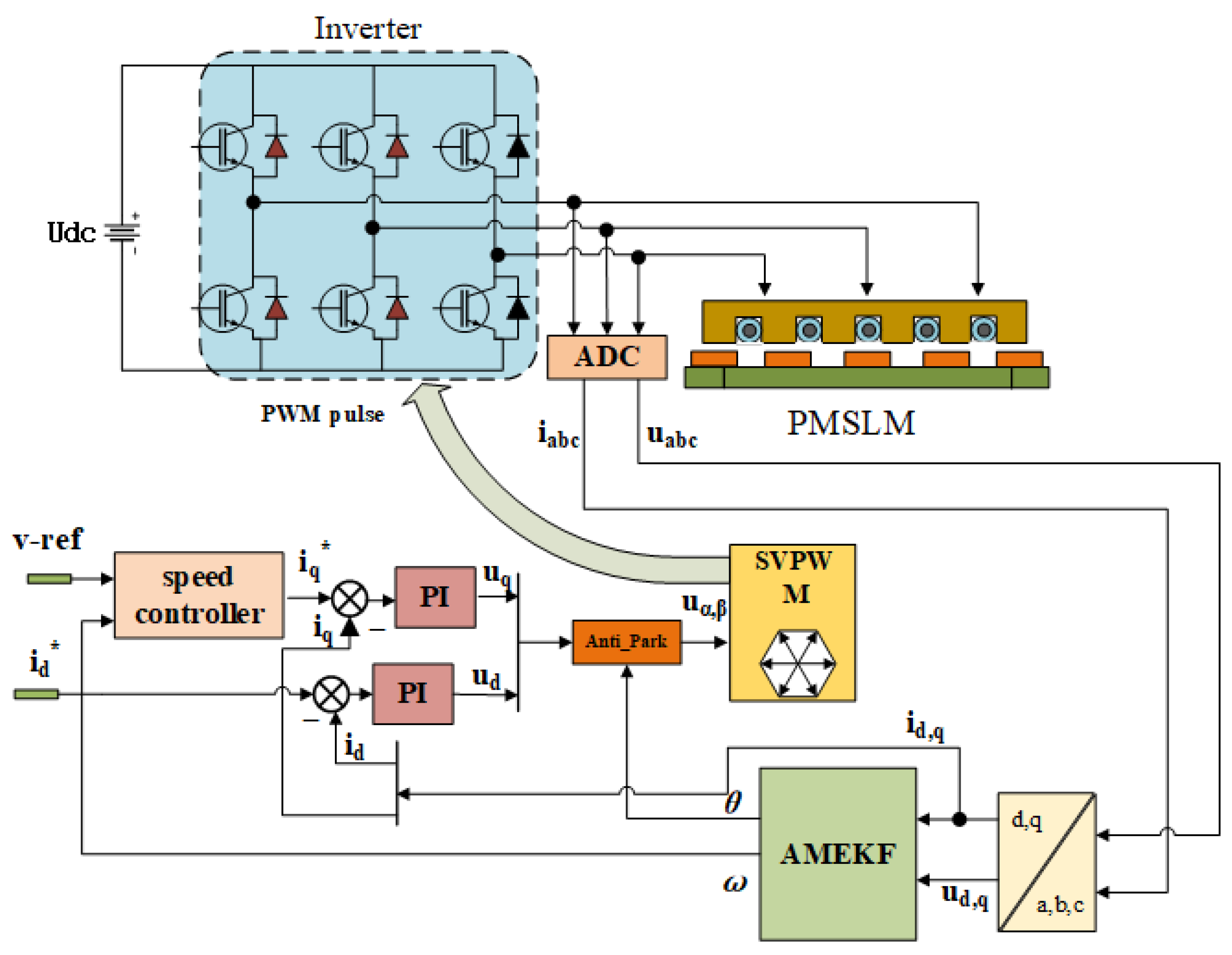
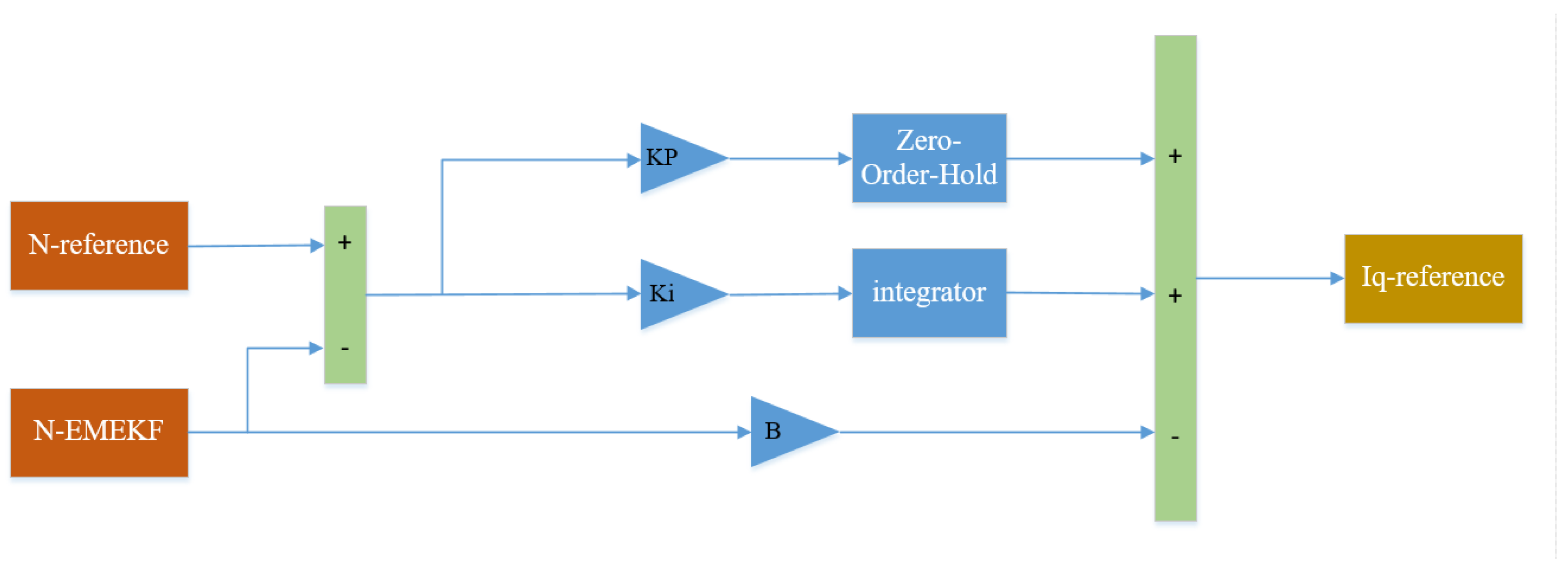
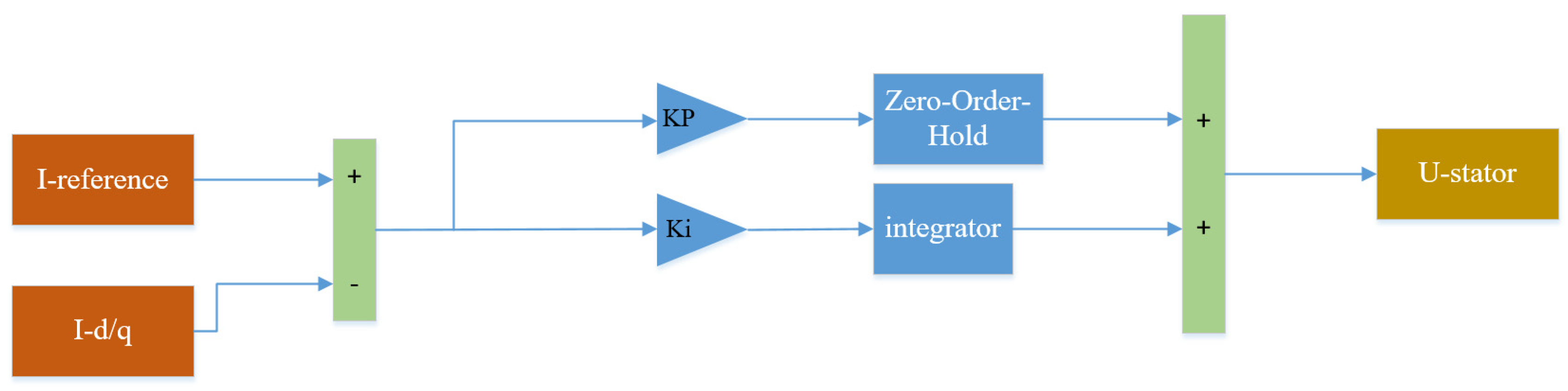
4.2. AMEKF Control Structure
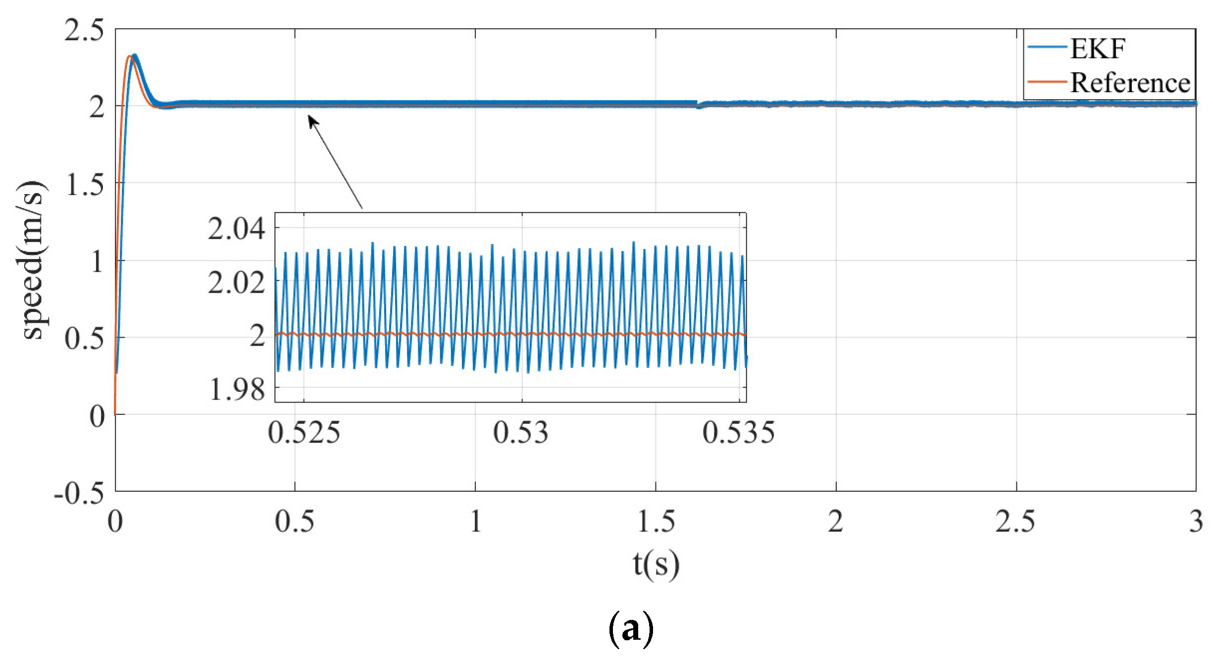
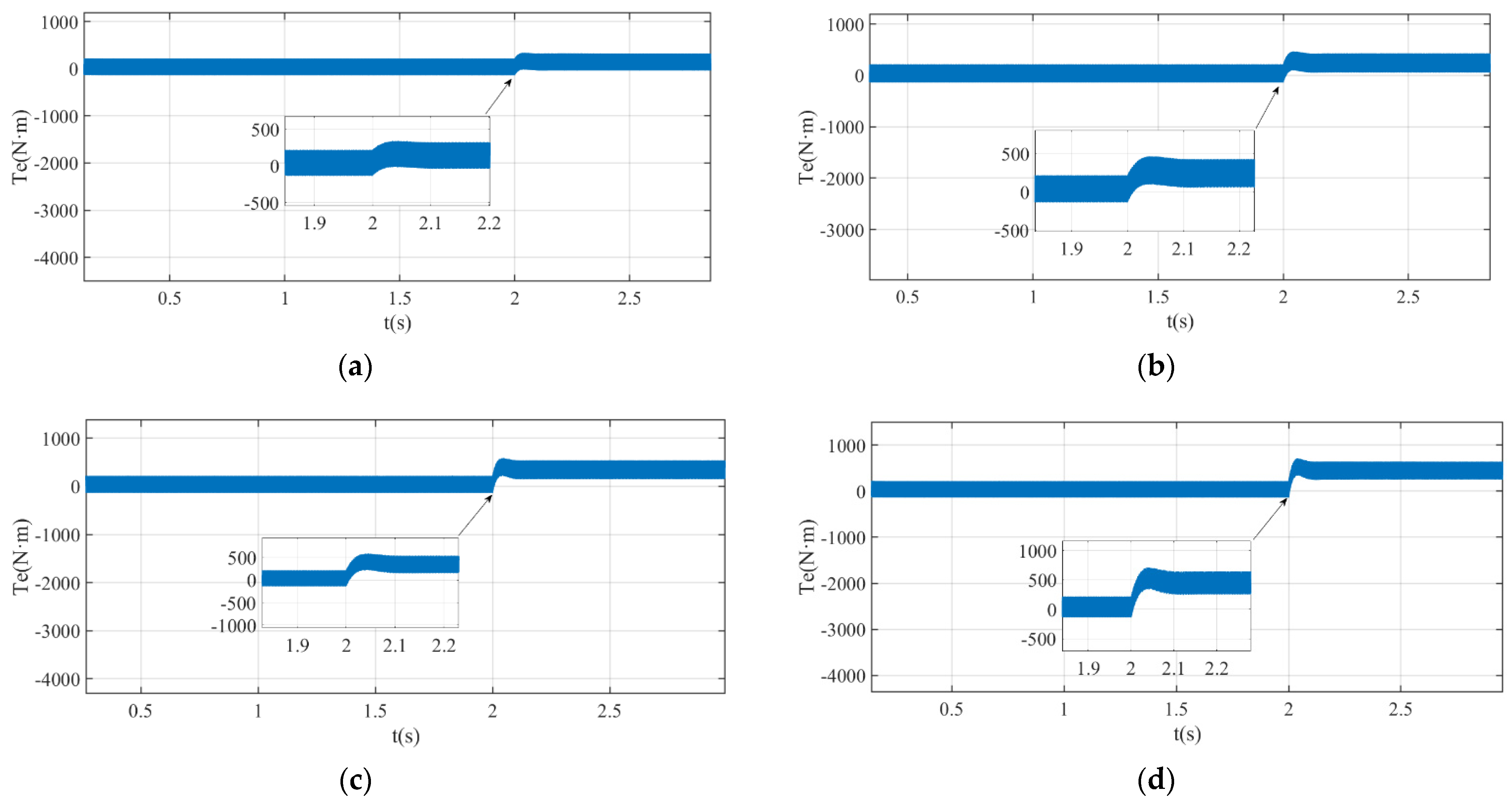
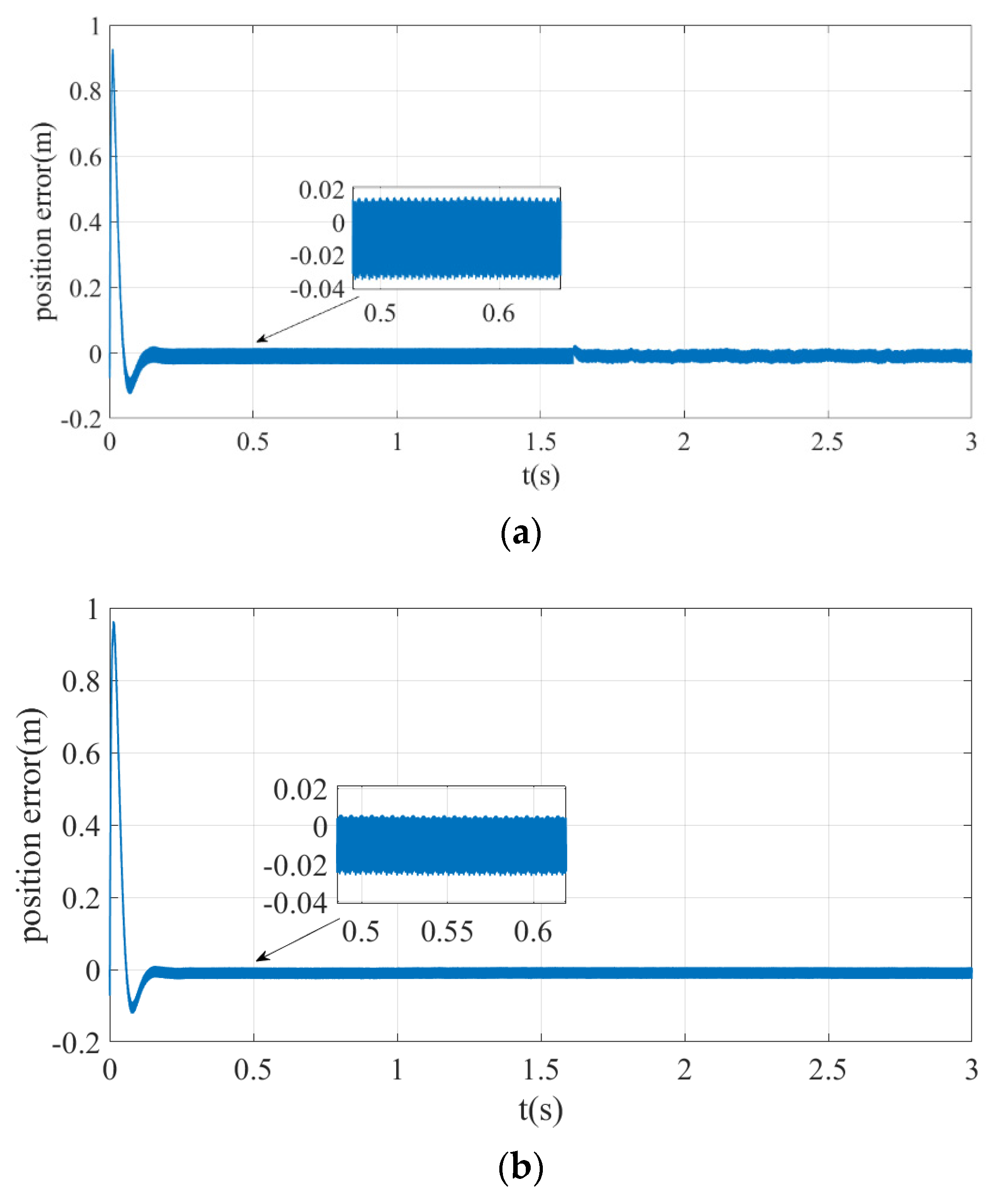
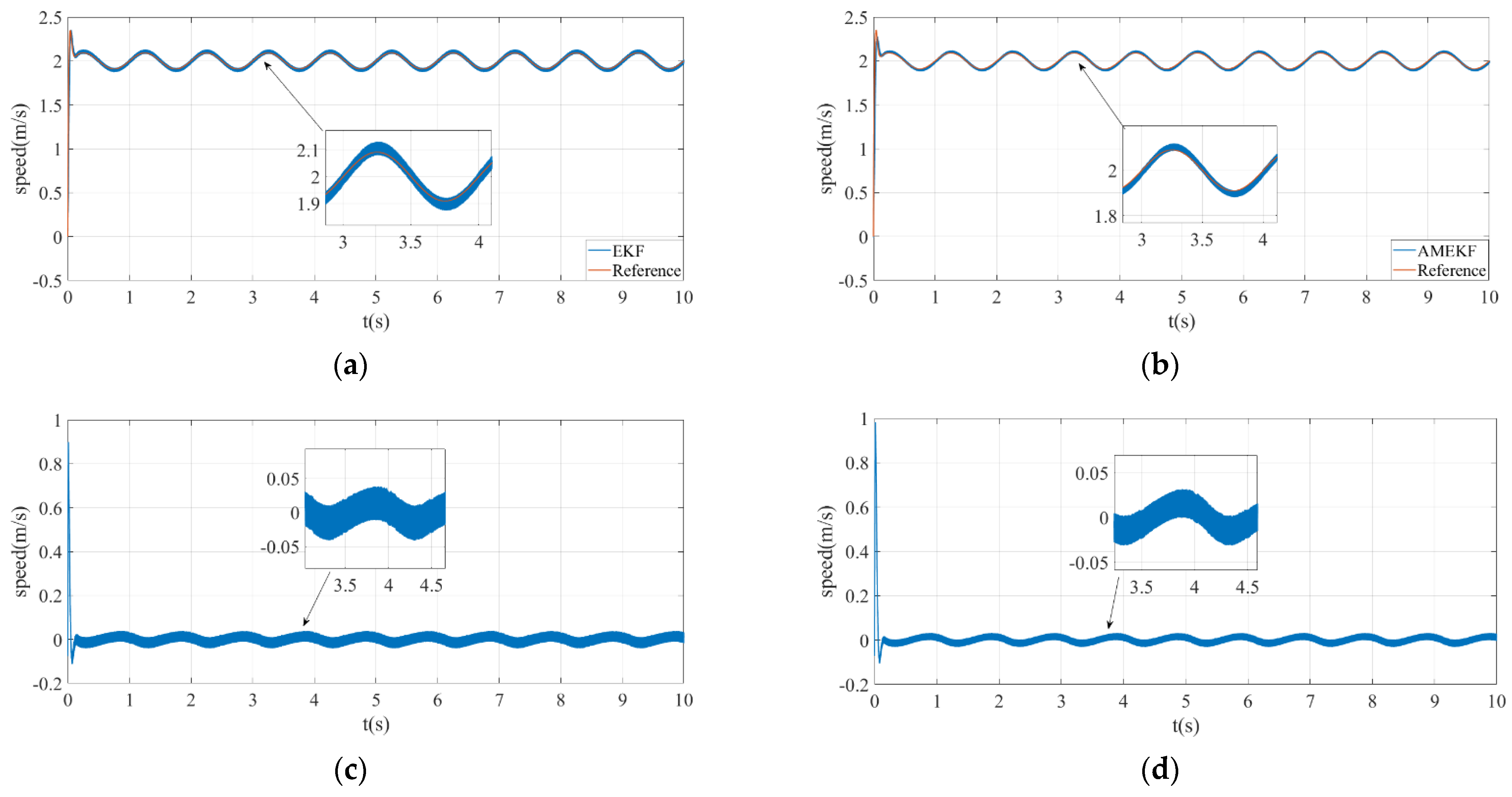
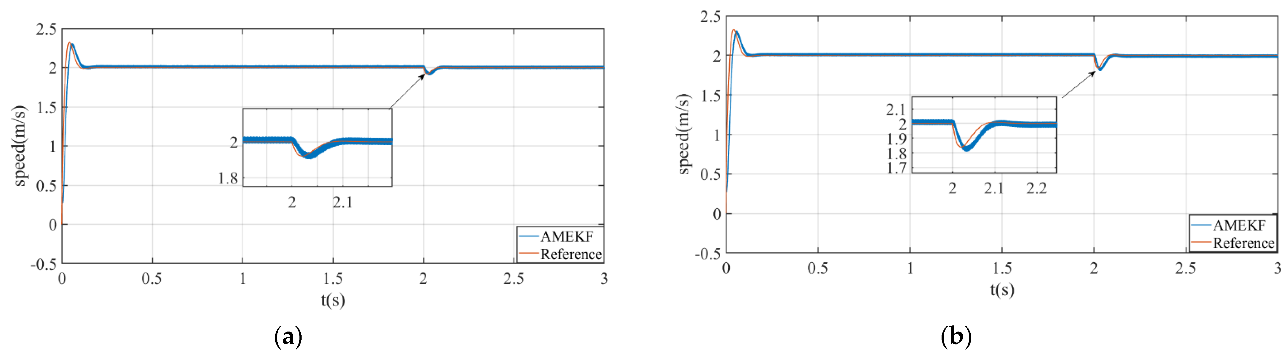
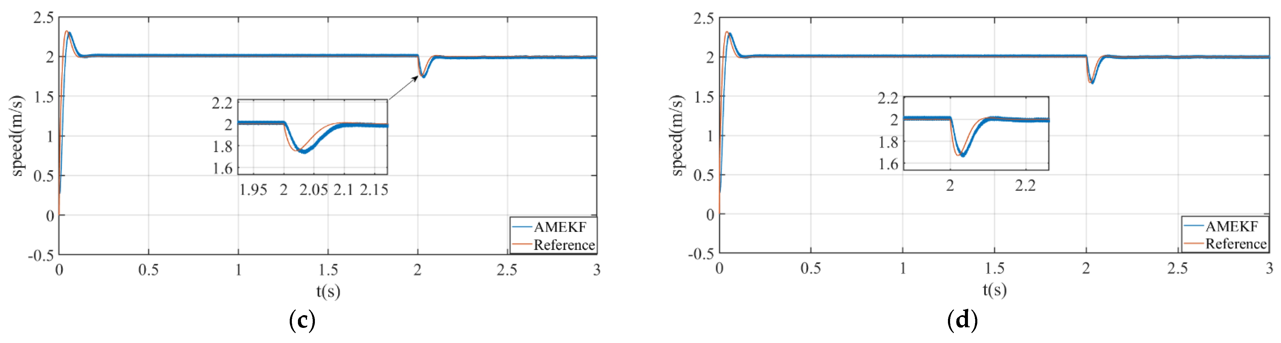
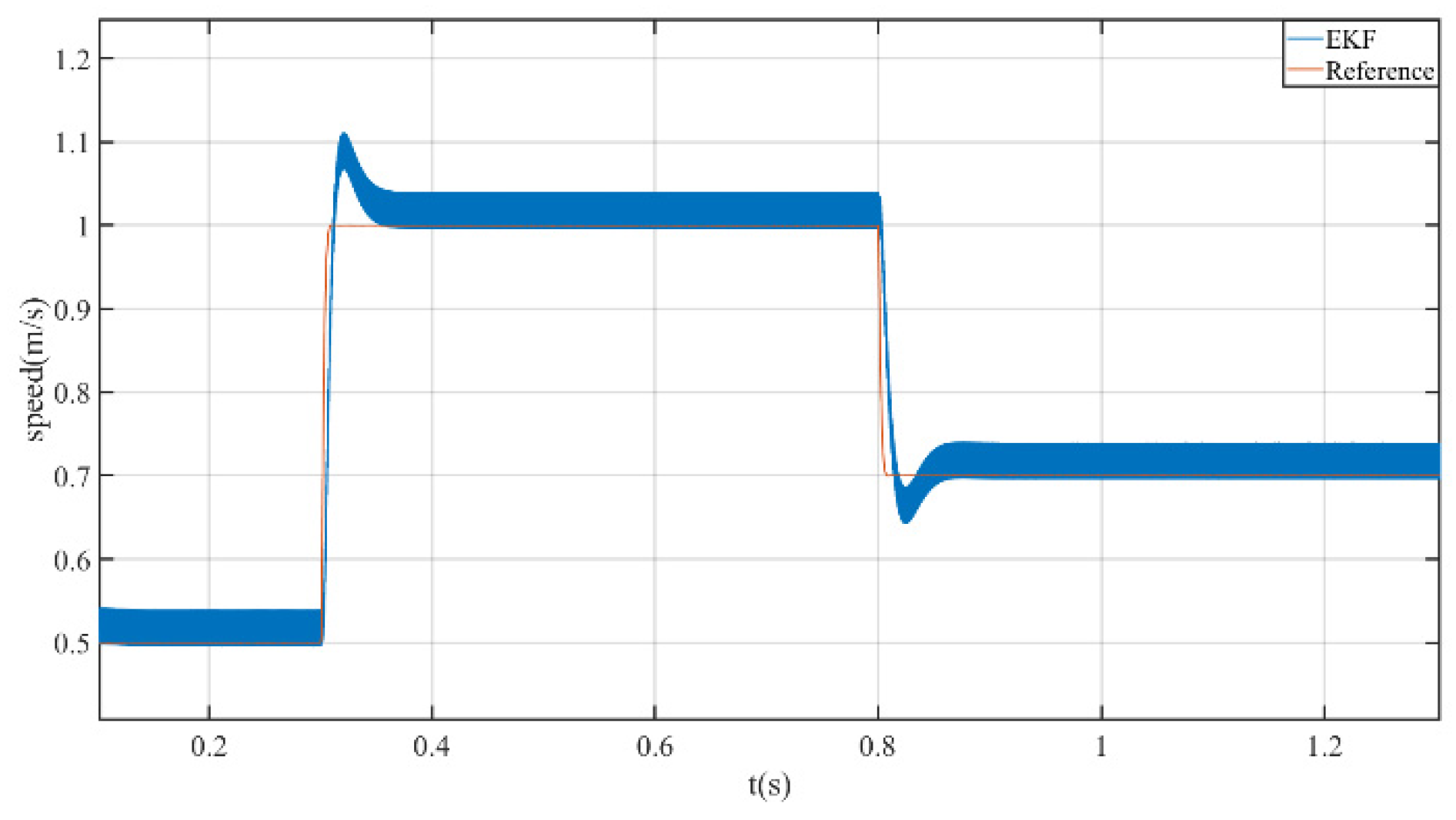
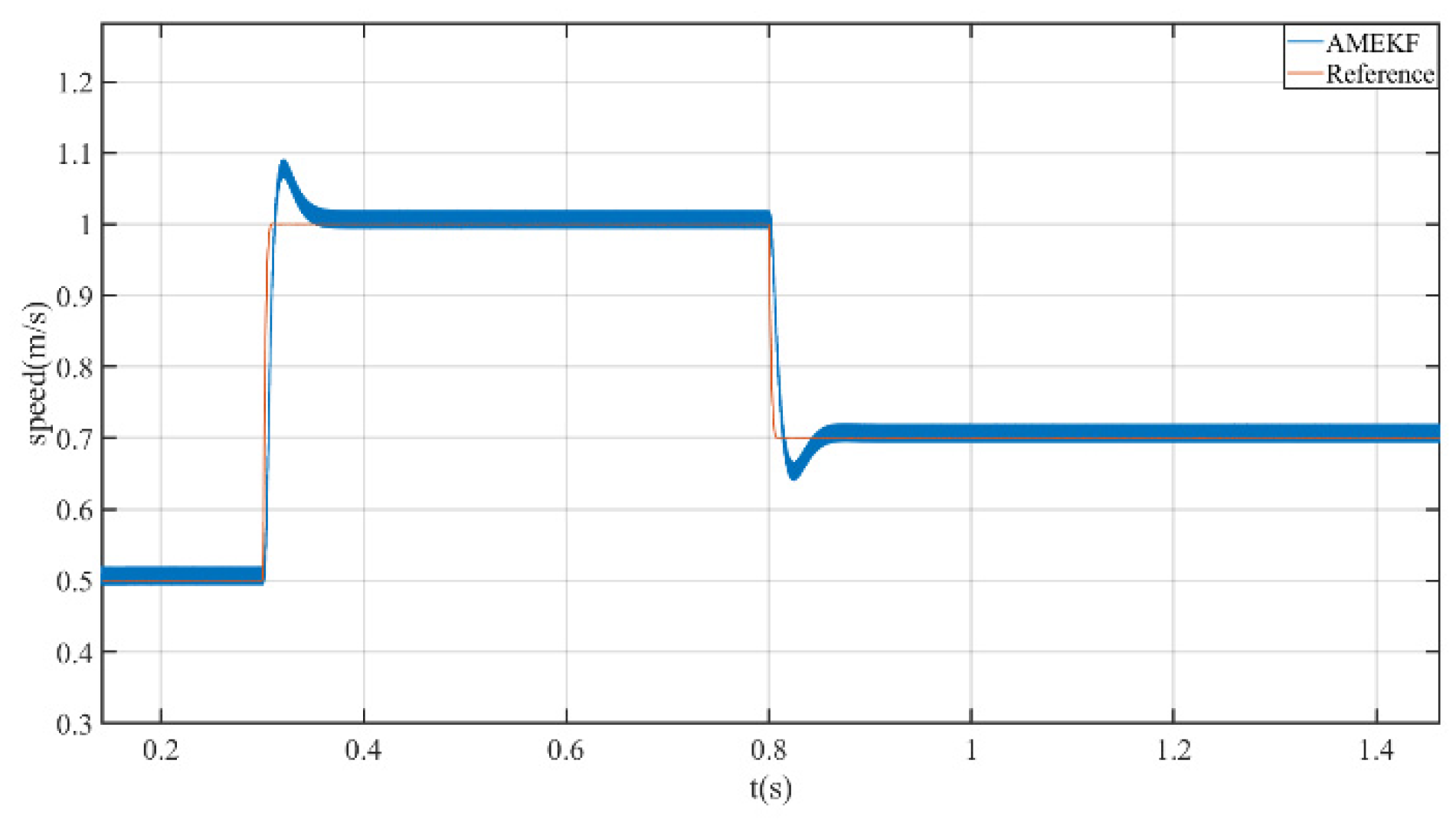
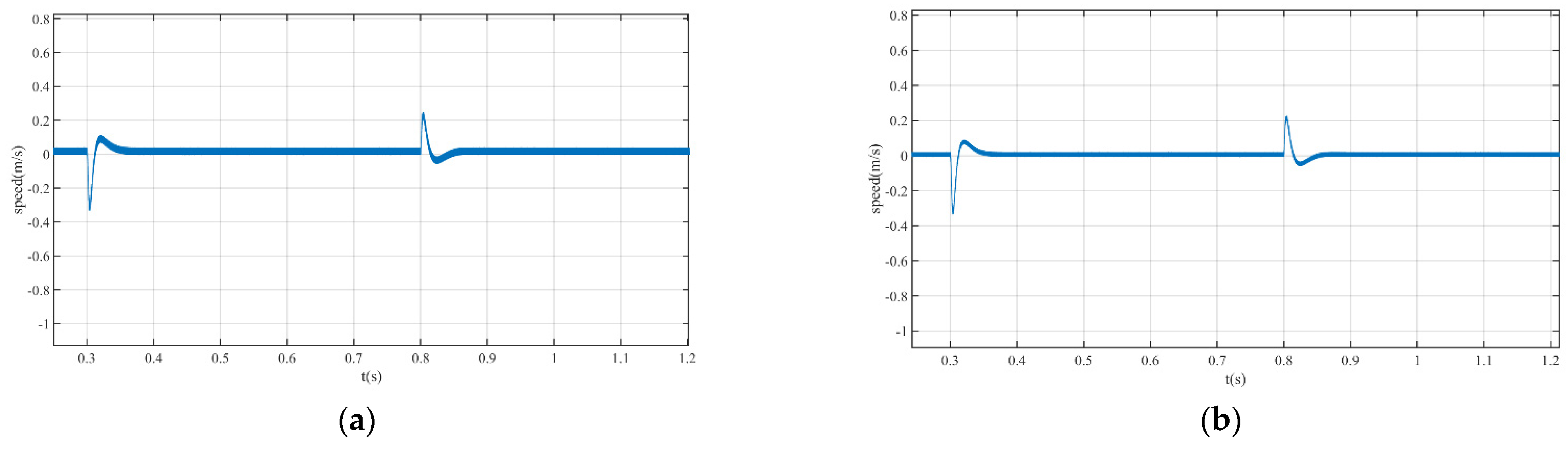
5. Simulation
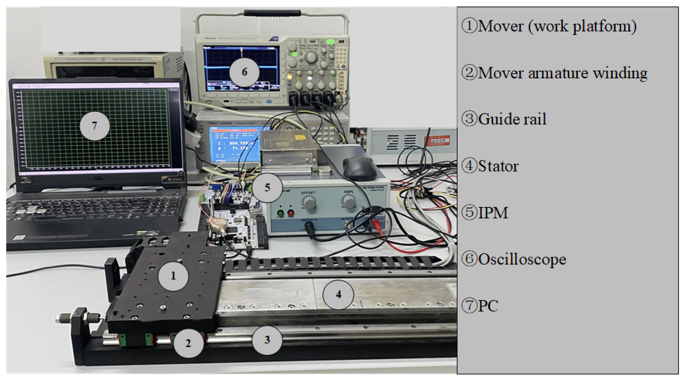
6. Experiment
7. Conclusions
Author Contributions
Funding
Conflicts of Interest
References
- Jing, Z.; Wang, W.; Zhou, Y.; Zhao, J. Robust high precision multi-frame motion detection for PMLSMs’ mover based on local upsampling moving least square method. Mech. Syst. Signal Process. 2021, 159, 107803. [Google Scholar]
- Li, L.; Liu, Y.; Li, L.; Tan, J. Kalman-Filtering Based Iterative Feedforward Tuning in Presence of Stochastic Noise: With Application to a Wafer Stage. IEEE Trans. Ind. Inform. 2019, 15, 5816–5826. [Google Scholar] [CrossRef]
- Yang, R.; Wang, M.; Li, L.; Wang, G.; Zhong, C. Robust Predictive Current Control of PMLSM with Extended State Modeling Based Kalman Filter: For Time-Varying Disturbance Rejection. IEEE Trans. Power Electron. 2020, 35, 2208–2221. [Google Scholar] [CrossRef]
- Ali, N.; Liu, Z.; Armghan, H.; Armghan, A. Super-twisting sliding mode controller for maximum power transfer efficiency tracking in hybrid energy storage based wireless in-wheel motor. Sustain. Energy Technol. Assess. 2022, 52, 102075. [Google Scholar] [CrossRef]
- Pallavolu, M.R.; Kumar, Y.A.; Mani, G.; Alshgari, R.A.; Ouladsmane, M.; Joo, S.W. Facile fabrication of novel heterostructured tin disulfide (SnS2)/tin sulfide (SnS)/N-CNO composite with improved energy storage capacity for high-performance supercapacitors. J. Electroanal. Chem. 2021, 899, 115695. [Google Scholar] [CrossRef]
- Kumar, Y.A.; Kumar, K.D.; Kim, H.-J. A novel electrode for supercapacitors: Efficient PVP-assisted synthesis of Ni3S2 nanostructures grown on Ni foam for energy storage. Dalton Trans. 2020, 49, 4050–4059. [Google Scholar] [CrossRef]
- Peng, Z. Predictive Current Control of Permanent Magnet Synchronous Motor Based on Parameter Identification; Harbin Institute of Technology: Harbin, China, 2017. [Google Scholar]
- Sultn, H.M. Design and Modeling of a Robust Sensorless Control System for a Linear Permanent Magnet Synchronous Motor. Electronics 2021, 10, 966. [Google Scholar]
- Chen, L.; Lichuan, L.I. Development of the Linear Motor and Its Key Technologies for Reciprocating Compressors. Proc. CSEE 2013, 33, 52–68. [Google Scholar] [CrossRef]
- Yin, Z.; Bai, C.; Du, C.; Liu, J. Predictive Beat Current Control Method for Permanent Magnet Synchronous Linear Motor Based on Internal Mode Disturbance Observer. Electrotech. J. 2018, 24, 5741–5750. [Google Scholar] [CrossRef]
- Li, D.E. Low Speed Performance Improvement of Sensorless Vector Control for Induction Motor Based on EKF; Xi’an University of Science and Technology: Xi’an, China, 2021. [Google Scholar] [CrossRef]
- Zhu, J.; Liu, B.; Wang, H.; Li, Z.; Zhang, Z. Research on Sensorless Control of PMLSM Based on improved volume Kalman Control engineering. Control Eng. China 2021, 28, 471–477. [Google Scholar] [CrossRef]
- Li, X.; Du, J.; Liang, D.; Huang, L.; Lou, J. Sensorless low speed control of permanent magnet linear motor based on improved pulse injection method. J. Electr. Mach. Control 2018, 22, 30–36. [Google Scholar]
- Heidari, H.; Rassõlkin, A.; Razzaghi, A.; Vaimann, T.; Kallaste, A.; Andriushchenko, E.; Belahcen, A.; Lukichev, D.V. A Modified Dynamic Model of Single-Sided Linear Induction Motors Considering Longitudinal and Transversal Effects. Electronics 2021, 10, 933. [Google Scholar] [CrossRef]
- Taghavifar, H. EKF estimation based PID Type-2 fuzzy control of electric cars. Measurement 2020, 173, 108557. [Google Scholar] [CrossRef]
- Dong, X.; Zhang, C.; Jiang, J. Evaluation of SOC Estimation Method Based on EKF/AEKF under Noise Interference. Energy Procedia 2018, 152, 520–525. [Google Scholar]
- Kumar, Y.A.; Kim, H.J. Preparation and electrochemical performance of NiCo2O4@NiCo2O4 composite nanoplates for high performance supercapacitor applications. New J. Chem. 2018, 42, 19971–19978. [Google Scholar] [CrossRef]
- Abelrahem, M.; Hackl, C.; Kennel, R. Robust Predictive Control Scheme for Permanent-Magnet Synchronous Generators Based Modern Wind Turbines. Electronics 2021, 10, 1596. [Google Scholar] [CrossRef]
- Li, Z.; An, J.; Xiao, Y.; Zhang, Q.; Sun, H. Design of Model Predictive Control System for Permanent Magnet Synchronous Linear Motor Based on Adaptive Observer. Electrotech. J. 2021, 4, 1190–1200. [Google Scholar] [CrossRef]
- Li, Z.; Wang, R.Y.; Xiao, Y.; Zhou, S.; Shi, Y.; Xue, Z. Ant colony since the optimal sliding mode control in the application of permanent magnet synchronous linear motor. J. Hunan Univ. Sci. Technol. 2020, 35, 77–84. [Google Scholar] [CrossRef]
- Kung, Y.S.; Thanh, N.P.; Wang, M.S. Design and simulation of a sensorless permanent magnet synchronous motor drive with microprocessor-based PI controller and dedicated hardware EKF estimator. Appl. Math. Model. 2015, 39, 5816–5827. [Google Scholar] [CrossRef]
- Lin, Y.P. Speed Control of Sensorless BLDCM Based on EKF Phase Gain Correction. Electric. Drive 2007, 37, 12–15. [Google Scholar] [CrossRef]
- Liu, H.P.; Zhang, Q.F. Research on a Modified EKF for Speed Estimation in Induction Motor Drives. In Proceedings of the 2007 IEEE International Conference on Integration Technology, Shenzhen, China, 20–24 March 2007. [Google Scholar]
- Leite, A.V.; Araujo, R.E.; Freitas, D. Full and reduced order extended Kalman filter for speed estimation in induction motor drives: A comparative study. In Proceedings of the 2004 IEEE 35th Annual Power Electronics Specialists Conference (IEEE Cat. No.04CH37551), Aachen, Germany, 20–25 June 2004. [Google Scholar]
- Yin, Z.; Xiao, L.; Sun, X.; Liu, J.; Zhong, Y. Speed Estimation method of Fuzzy Extended Kalman Filter for Induction Motor Based on Particle Swarm Optimization. Electrotech. J. 2016, 31, 55–65. [Google Scholar] [CrossRef]
- Hernandez-Barragan, J.; Rios, J.D.; Alanis, A.Y.; Lopez-Franco, C.; Gomez-Avila, J.; Arana-Daniel, N. Adaptive Single Neuron Anti-Windup PID Controller Based on the Extended Kalman Filter Algorithm. Electronics 2020, 9, 636. [Google Scholar] [CrossRef]


| Parameter | Value |
|---|---|
| Stator resistance Rs/Ω | 2.875 |
| d-q axis inductance Ldq/mH | 8.5 |
| Mover mass m/kg | 1.425 |
| Viscous friction coefficient B/N/m⋅s | 20 |
| Continuous thrust F/N | 32 |
| Polar distance τ/m | 0.018 |
| Fluctuation Range at 2 m/s Speed (m/s) | Error Percentage | Velocity Fluctuation Range under Sinusoidal Velocity | Error Percentage | |
|---|---|---|---|---|
| EKF | −0.015–0.03 | 2.25% | ±0.04 | 4% |
| AMEKF | −0.01–0.02 | 1.5% | ±0.025 | 2.5% |
Publisher’s Note: MDPI stays neutral with regard to jurisdictional claims in published maps and institutional affiliations. |
© 2022 by the authors. Licensee MDPI, Basel, Switzerland. This article is an open access article distributed under the terms and conditions of the Creative Commons Attribution (CC BY) license (https://creativecommons.org/licenses/by/4.0/).
Share and Cite
Li, Z.; Zhang, L.; Wang, J.; Sun, W.; Wang, P.; Guo, X.; Sun, H. Speed Estimation Method of Linear Motor Extended Kalman Filter Based on Attenuation Memory. Electronics 2022, 11, 1543. https://doi.org/10.3390/electronics11101543
Li Z, Zhang L, Wang J, Sun W, Wang P, Guo X, Sun H. Speed Estimation Method of Linear Motor Extended Kalman Filter Based on Attenuation Memory. Electronics. 2022; 11(10):1543. https://doi.org/10.3390/electronics11101543
Chicago/Turabian StyleLi, Zheng, Lucheng Zhang, Jinsong Wang, Weisong Sun, Pengju Wang, Xiaoqiang Guo, and Hexu Sun. 2022. "Speed Estimation Method of Linear Motor Extended Kalman Filter Based on Attenuation Memory" Electronics 11, no. 10: 1543. https://doi.org/10.3390/electronics11101543
APA StyleLi, Z., Zhang, L., Wang, J., Sun, W., Wang, P., Guo, X., & Sun, H. (2022). Speed Estimation Method of Linear Motor Extended Kalman Filter Based on Attenuation Memory. Electronics, 11(10), 1543. https://doi.org/10.3390/electronics11101543