
A Path Planning Method for Underground Intelligent Vehicles Based on an Improved RRT* Algorithm

Abstract
:1. Introduction
2. Related Works
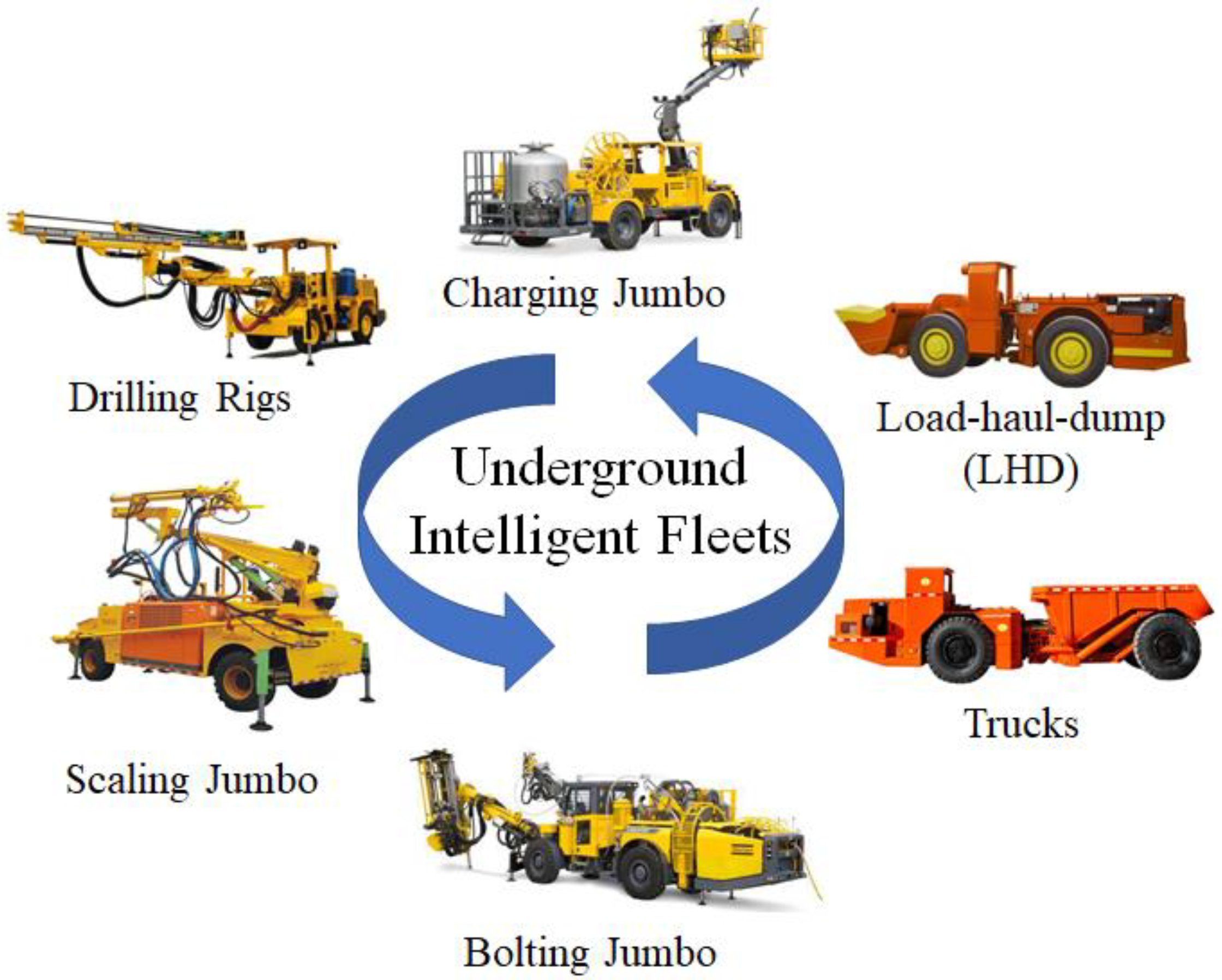
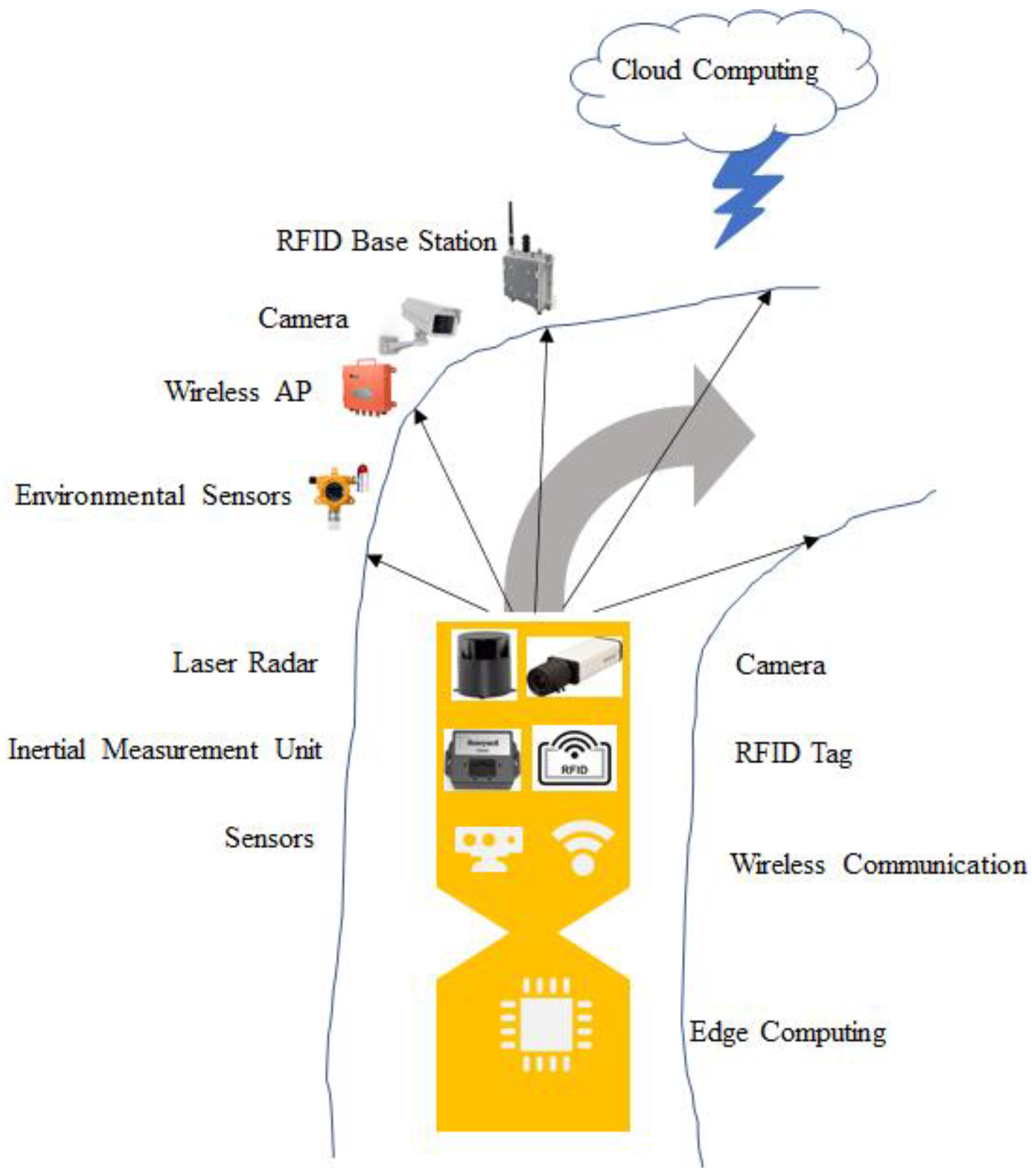
2.1. Underground Intelligent Vehicles
2.2. Path Planning Methods
3. Constraints Formulation
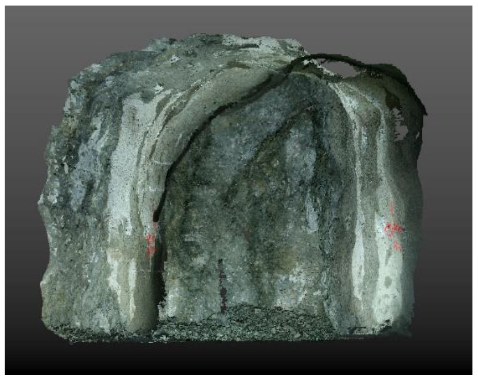
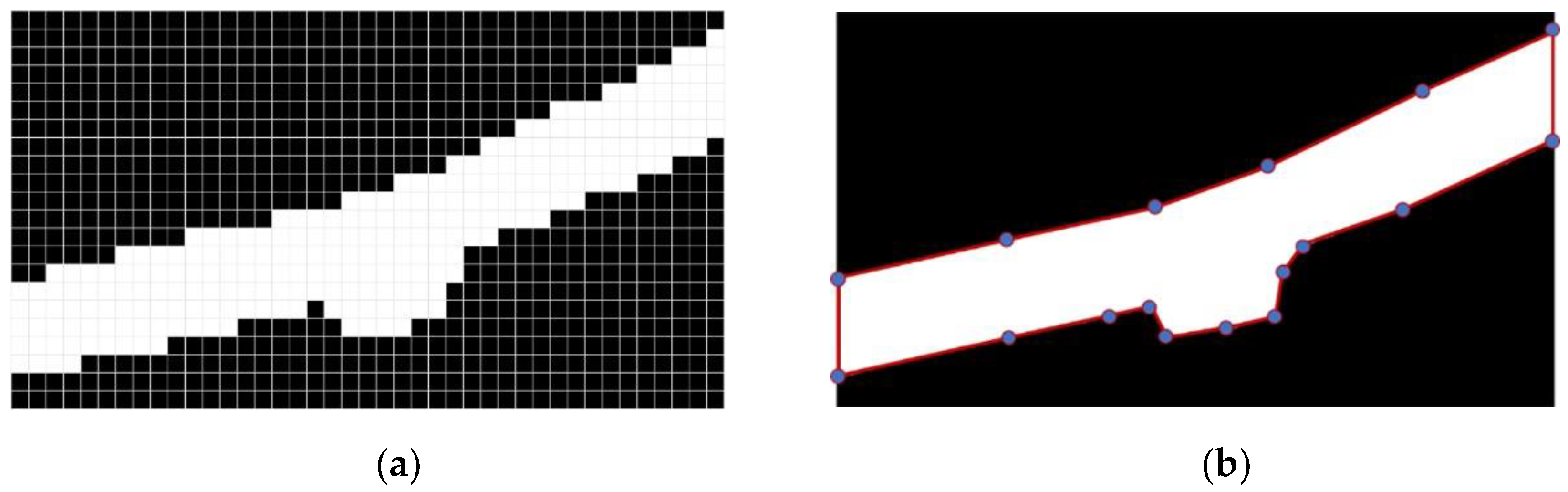
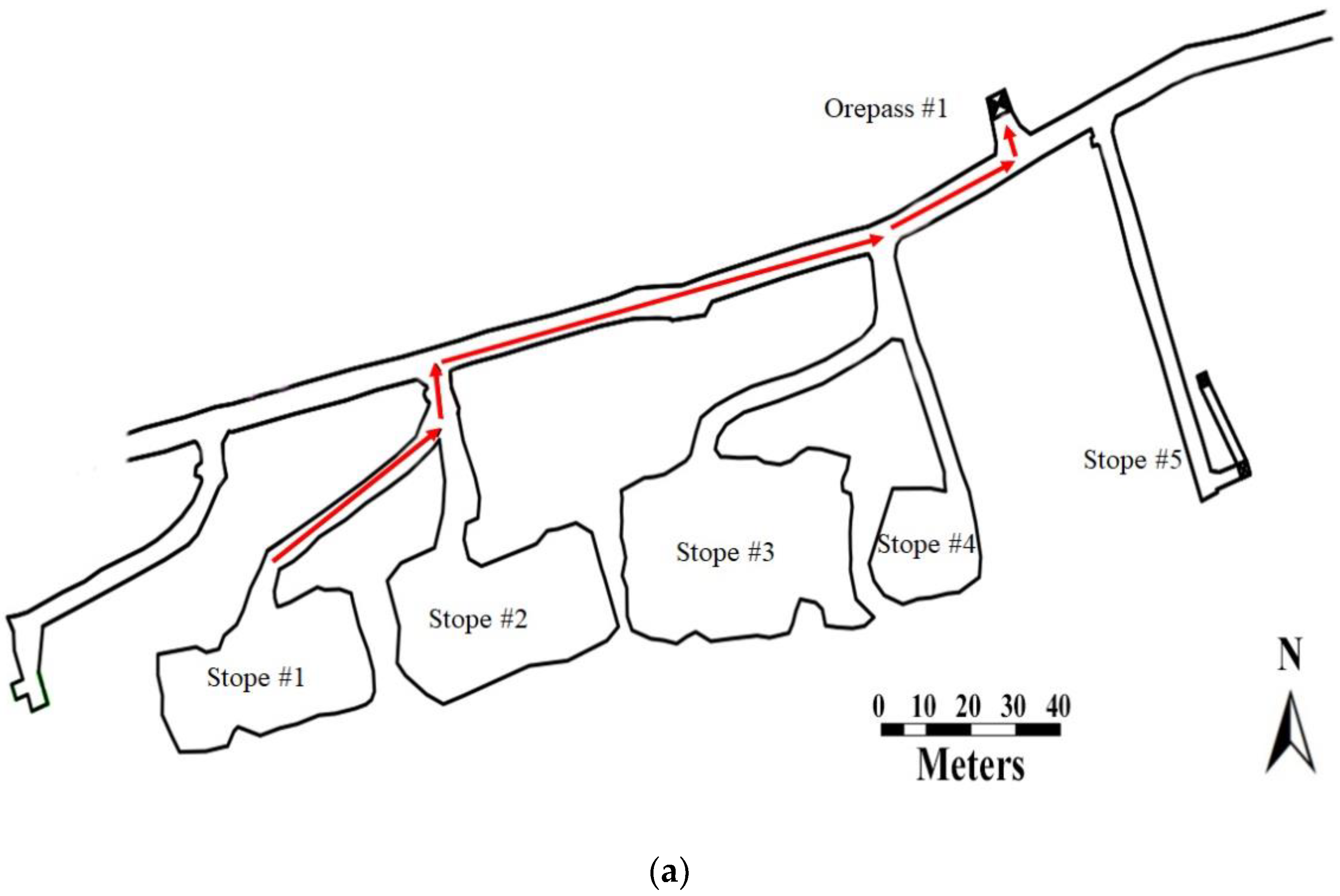
3.1. Drift Environment Formulation
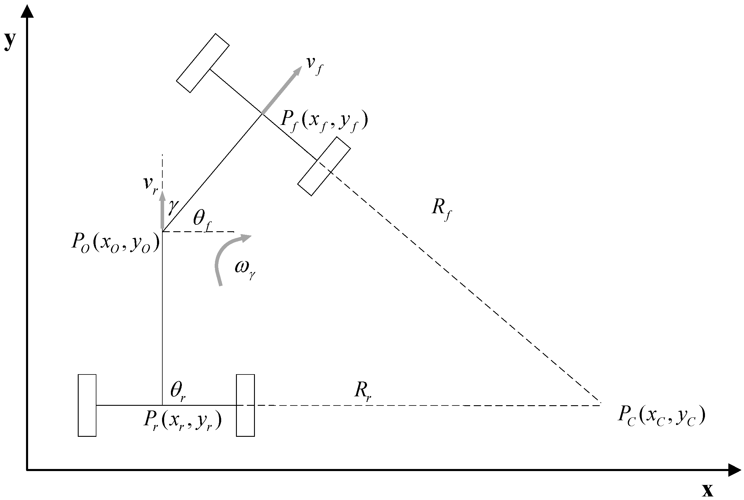
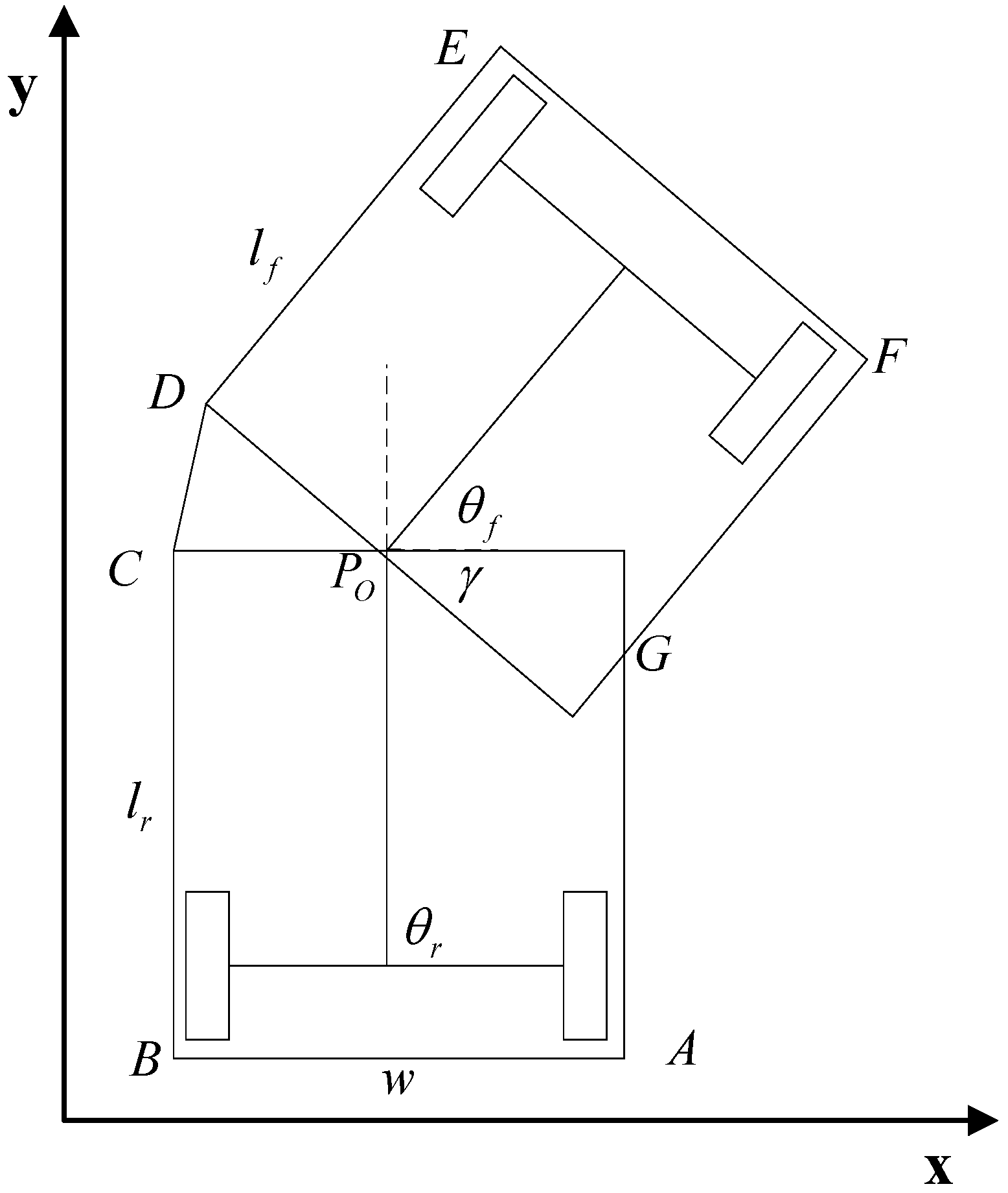
3.2. Kinematics of Vehicles
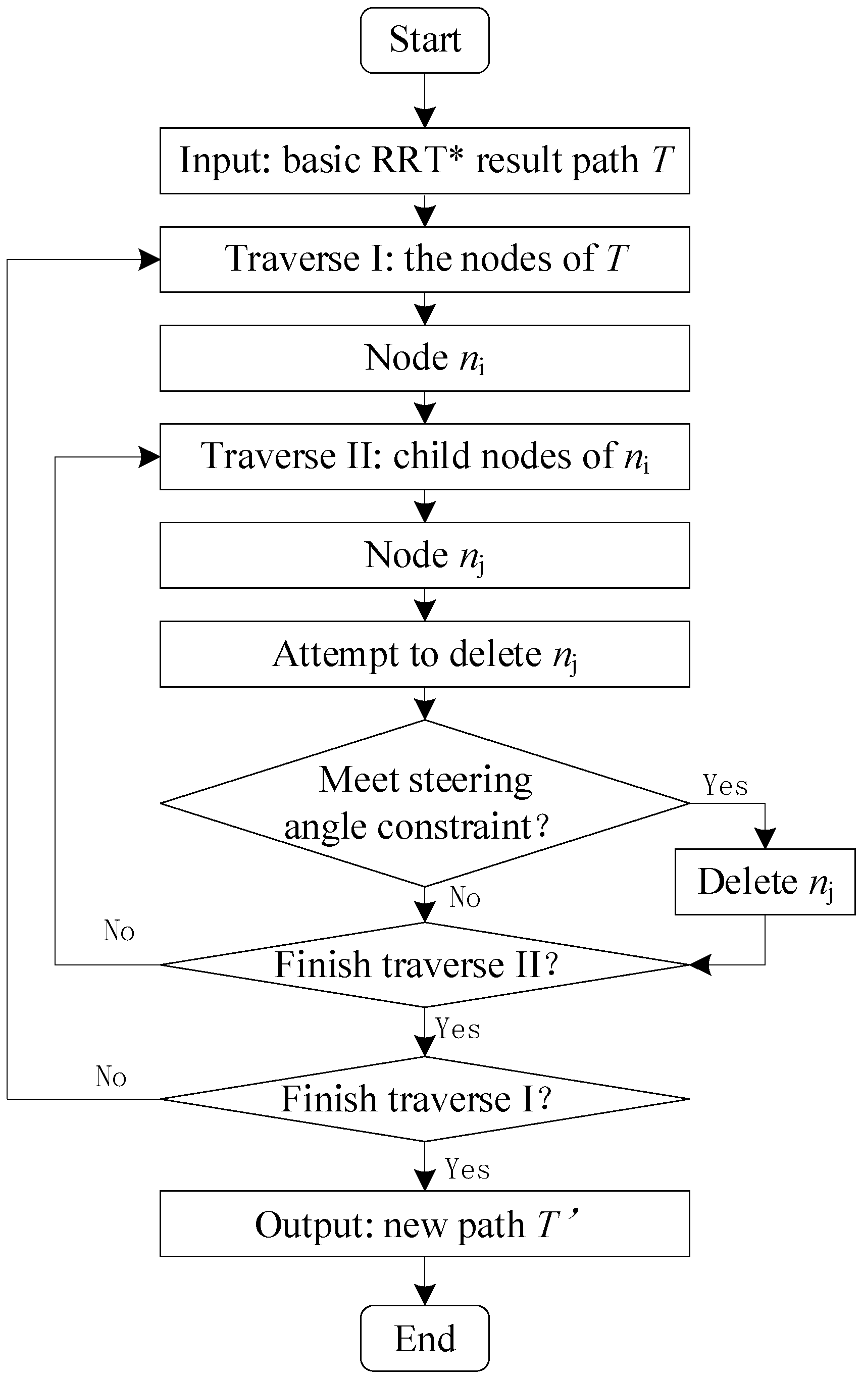
4. Improved RRT* Algorithm for Intelligent Vehicles
- (1)
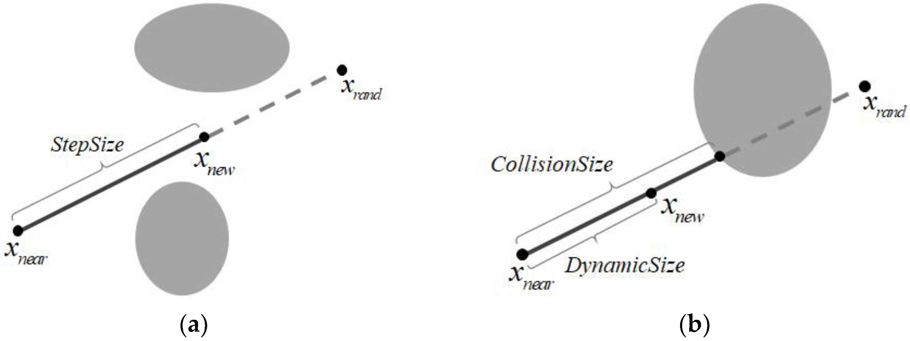
- The underground drift is long and narrow, and the available area of the entire map is small. The RRT* algorithm uses fixed-step full-map sampling, which results in low sampling efficiency in the scene of the drift map;
- (2)
- Drifts are usually constructed by a drilling and blasting method, and their surface will inevitably be irregular. As a result, the map of drifts cannot be as smooth as a regular road map, which will affect the smoothness of the solution path;
- (3)
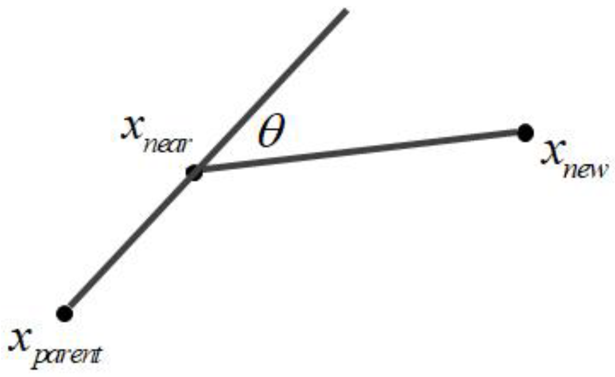
- Underground vehicles are usually large in size, and the steering radius should be strictly controlled during their driving. Due to the randomness of the expansion, the RRT* algorithm cannot guarantee a path that meets the steering radius of the vehicles.
- (1)
- Dynamic step size
- (2)
- Steering angle constraints
- (3)
- Optimal tree reconnection
| Algorithm 1 Improved RRT* Algorithm | |
| Input: , , Map Output: A path T from to | |
| 1 | T.initalize(); |
| 2 | for i = 1 to n do |
| 3 | while true do |
| 4 | ←Sample(Map); |
| 5 | ←Near(, T); |
| 6 | DynamicSize←CollisionCheck(, Map); |
| 7 | ←Steer(,,DynamicSize); |
| 8 | if CollisionFree(, Map) and Turnable(, , ) then |
| 9 | break; |
| 10 | end |
| 11 | end |
| 12 | ←NearNeighbour(, T) |
| 13 | foreach do |
| 14 | Test_dis←Cost() + Distance(, ) |
| 15 | if CollisionFree(, , Map) and Test_dis < Cost() then |
| 16 | ←Parent(); |
| 17 | Update(T); |
| 18 | end |
| 19 | end |
| 20 | if = then |
| 21 | T←OptimalTreeReconnection(T); |
| 22 | success(); |
| 23 | end |
| 24 | end |
5. Simulation Analysis
5.1. Simulation Environment
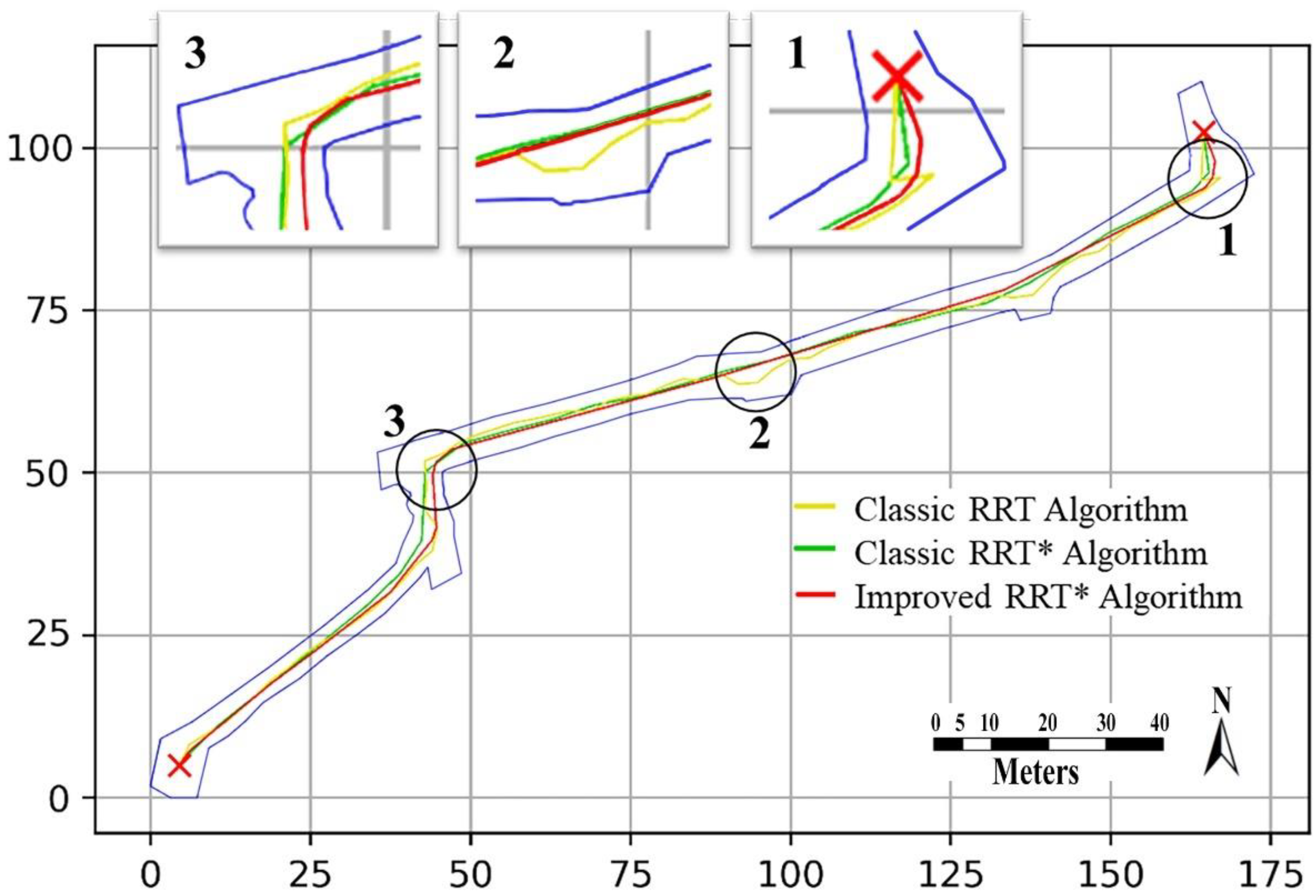
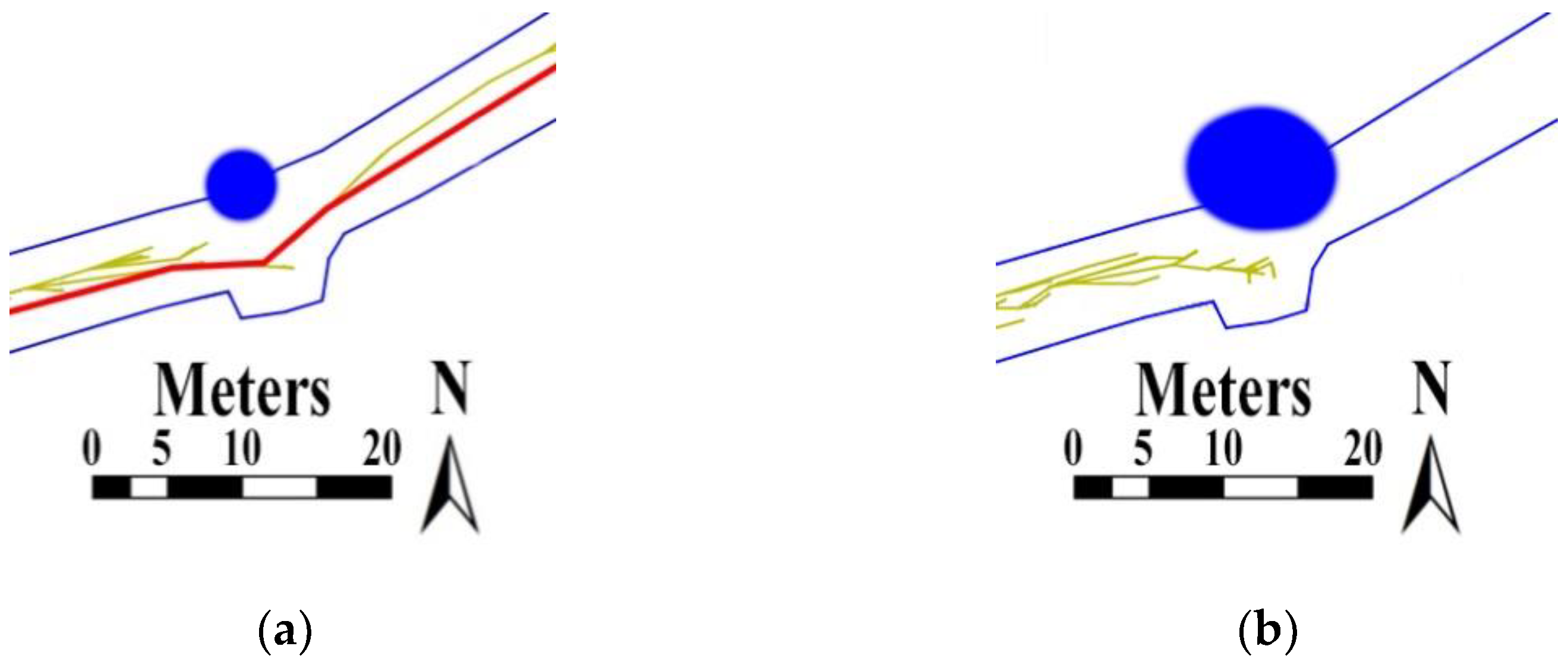
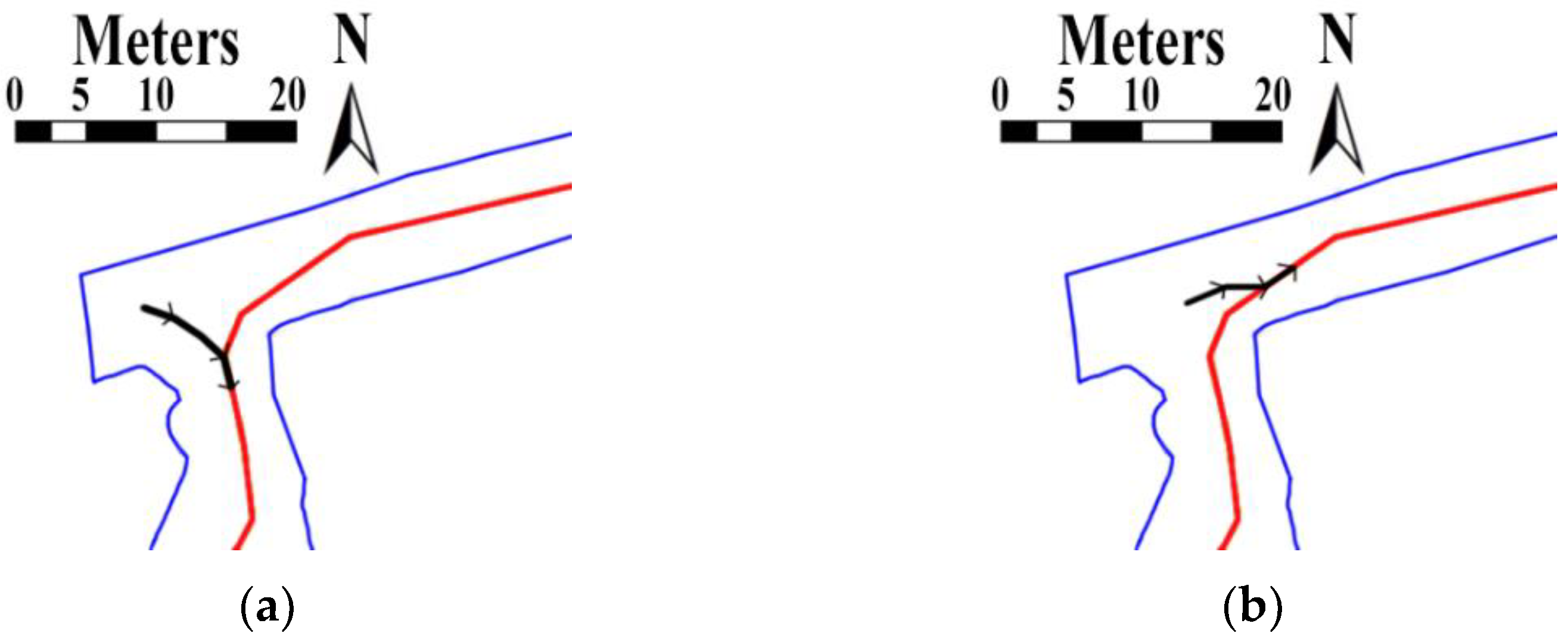
5.2. Simulation Results
5.3. Discussion
6. Conclusions
Author Contributions
Funding
Data Availability Statement
Acknowledgments
Conflicts of Interest
References
- Guo, H.; Zhu, K.; Ding, C.; Li, L. Intelligent optimization for project scheduling of the first mining face in coal mining. Expert Syst. Appl. 2010, 37, 1294–1301. [Google Scholar] [CrossRef]
- Li, J.G.; Zhan, K. Intelligent Mining Technology for an Underground Metal Mine Based on Unmanned Equipment. Engineering 2018, 4, 11. [Google Scholar] [CrossRef]
- Lw, J.; Abrahamsson, L.; Johansson, J. Mining 4.0—The Impact of New Technology from a Work Place Perspective. Min. Metall. Explor. 2019, 36, 701–707. [Google Scholar]
- Sánchez, F.; Hartlieb, P. Innovation in the Mining Industry: Technological Trends and a Case Study of the Challenges of Disruptive Innovation. Min. Metall. Explor. 2020, 37, 1385–1399. [Google Scholar] [CrossRef]
- Chen, W.; Wang, X. Coal Mine Safety Intelligent Monitoring Based on Wireless Sensor Network. IEEE Sens. J. 2020, 21, 25465–25471. [Google Scholar] [CrossRef]
- Roberge, V.; Tarbouchi, M.; LaBonte, G. Comparison of Parallel Genetic Algorithm and Particle Swarm Optimization for Real-Time UAV Path Planning. Ind. Inform. IEEE Trans. 2012, 9, 132–141. [Google Scholar] [CrossRef]
- Tokekar, P.; Hook, J.V.; Mulla, D.; Isler, V. Sensor Planning for a Symbiotic UAV and UGV System for Precision Agriculture. IEEE Trans. Robot. 2016, 32, 1498–1511. [Google Scholar] [CrossRef]
- Chugh, Y.; Parkinson, H. Automation trends in room-and-pillar continous-mining systems in the USA. J. S. Afr. Inst. Min. Metall. 1981, 81, 57–65. [Google Scholar]
- Scoble, M. Canadian mining automation evolution: The digital mine en route to minewide automation. Int. J. Rock Mech. Min. Sci. Geomech. Abstr. 1995, 32, 351A. [Google Scholar]
- Kot-Niewiadomska, A. ROBOMINERS Project—The future of mining. In Proceedings of the 30th International Conference on the Present and Future of the Mining and Geology, Demanovska Dolina, Slovakia, 3–4 October 2019; Robominers: Demanovska Dolina, Slovakia, 2019; pp. 1–12. [Google Scholar]
- Bearne, G. Innovation in mining: Rio Tinto’s Mine of the Future (TM) programme. Alum. Int. Today 2014, 26, 15. [Google Scholar]
- Mullan, L. Spearheading a Digital Transformation in the Canadian Mining Industry; Swedish Mining Automation Group: Toronto, ON, Canada, 2017; pp. 1–3. [Google Scholar]
- Altafini, C. Why to use an articulated vehicle in underground mining operations? In Proceedings of the 1999 IEEE International Conference on Robotics and Automation, Detroit, MI, USA, 10–15 May 1999; pp. 3020–3025. [Google Scholar]
- Rodrigo, P. Mining Haul Roads: Theory and Practice; CRC Press: Boca Raton, FL, USA, 2019. [Google Scholar]
- Khatib, O. Real-Time Obstacle Avoidance System for Manipulators and Mobile Robots. Int. J. Robot. Res. 1986, 5, 90–98. [Google Scholar] [CrossRef]
- Luo, G.; Yu, J.I.; Mei, Y.O.; Zhang, S.Y. UAV Path Planning in Mixed-Obstacle Environment via Artificial Potential Field Method Improved by Additional Control Force. Asian J. Control 2015, 17, 1600–1610. [Google Scholar] [CrossRef]
- Malone, N.; Chiang, H.T.; Lesser, K.; Oishi, M.; Tapia, L. Hybrid Dynamic Moving Obstacle Avoidance Using a Stochastic Reachable Set-Based Potential Field. IEEE Trans. Robot. 2017, 33, 1124–1138. [Google Scholar] [CrossRef]
- Yang, W.; Wu, P.; Zhou, X.; Lv, H.; Liu, X.; Zhang, G.; Hou, Z.; Wang, W. Improved Artificial Potential Field and Dynamic Window Method for Amphibious Robot Fish Path Planning. Appl. Sci. 2021, 11, 2114. [Google Scholar] [CrossRef]
- Seder, M.; Baotic, M.; Petrovic, I. Receding Horizon Control for Convergent Navigation of a Differential Drive Mobile Robot. IEEE Trans. Control Syst. Technol. 2017, 25, 653–660. [Google Scholar] [CrossRef]
- Saad, M.; Salameh, A.I.; Abdallah, S.; El-Moursy, A.; Cheng, C.T. A Composite Metric Routing Approach for Energy-Efficient Shortest Path Planning on Natural Terrains. Appl. Sci. 2021, 11, 6939. [Google Scholar] [CrossRef]
- Biyela, P.; Rawatlal, R. Development of an optimal state transition graph for trajectory optimisation of dynamic systems by application of Dijkstra’s algorithm. Comput. Chem. Eng. 2019, 125, 569–586. [Google Scholar] [CrossRef]
- Goerzen, C.; Kong, Z.; Mettler, B. A Survey of Motion Planning Algorithms from the Perspective of Autonomous UAV Guidance. J. Intell. Robot. Syst. 2010, 57, 65. [Google Scholar] [CrossRef]
- Christie, G.A.; Shoemaker, A.; Kochersberger, K.B.; Tokekar, P.; Mclean, L.; Leonessa, A. Radiation search operations using scene understanding with autonomous UAV and UGV. J. Field Robot. 2017, 34, 1450–1468. [Google Scholar] [CrossRef] [Green Version]
- Zhuang, H.; Dong, K.; Qi, Y.; Wang, N.; Dong, L. Multi-Destination Path Planning Method Research of Mobile Robots Based on Goal of Passing through the Fewest Obstacles. Appl. Sci. 2021, 11, 7378. [Google Scholar] [CrossRef]
- Kavraki, L.E.; Svestka, P.; Latombe, J.C.; Overmars, M.H. Probabilistic Roadmaps for Path Planning in High-Dimensional Configuration Spaces. IEEE Trans. Robot. Autom. 1996, 12, 566–580. [Google Scholar] [CrossRef] [Green Version]
- Park, B.; Chung, W.K. Efficient environment representation for mobile robot path planning using CVT-PRM with Halton sampling. Electron. Lett. 2012, 48, 1397–1399. [Google Scholar] [CrossRef]
- LaValle, S.M.; Kuffner, J.J., Jr. Randomized kinodynamic planning. Int. J. Robot. Res. 2001, 20, 378–400. [Google Scholar] [CrossRef]
- Cui, R.; Yang, L.; Yan, W. Mutual Information-Based Multi-AUV Path Planning for Scalar Field Sampling Using Multidimensional RRT*. IEEE Trans. Syst. Man Cybern. Syst. 2017, 46, 993–1004. [Google Scholar] [CrossRef]
- Shome, R.; Solovey, K.; Dobson, A.; Halperin, D.; Bekris, K.E. dRRT*: Scalable and informed asymptotically-optimal multi-robot motion planning. Auton. Robot. 2020, 44, 443–467. [Google Scholar] [CrossRef] [Green Version]
- Lavalle, S.M. Rapidly-Exploring Random Trees: A New Tool for Path Planning. Res. Rep. 1998, RT98-11, 1–4. [Google Scholar]
- Karaman, S.; Frazzoli, E. Optimal Kinodynamic Motion Planning using Incremental Sampling-based Methods. In Proceedings of the IEEE Conference on Decision & Control, Atlanta, GA, USA, 15–17 December 2010; pp. 7681–7687. [Google Scholar]
- Ma, X.; Mao, R. Path planning for coal mine robot to avoid obstacle in gas distribution area. Int. J. Adv. Robot. Syst. 2018, 15, 172988141775150. [Google Scholar] [CrossRef] [Green Version]
- Mauricio, A.; Nieves, A.; Castillo, Y.; Hilasaca, K.; Fonseca, C.; Gallardo, J.; Rodríguez, R.; Rodríguez, G. Multi-robot exploration and mapping strategy in underground mines by behavior control. In Multibody Mechatronic Systems; Springer: Berlin/Heidelberg, Germany, 2015; pp. 101–110. [Google Scholar]
- Papachristos, C.; Khattak, S.; Mascarich, F.; Dang, T.; Alexis, K. Autonomous Aerial Robotic Exploration of Subterranean Environments relying on Morphology–aware Path Planning. In Proceedings of the 2019 International Conference on Unmanned Aircraft Systems (ICUAS), Atlanta, GA, USA, 11–14 June 2019; pp. 299–305. [Google Scholar]
- Gamache, M.; Grimard, R.; Cohen, P. A shortest-path algorithm for solving the fleet management problem in underground mines. Eur. J. Oper. Res. 2005, 166, 497–506. [Google Scholar] [CrossRef]
- Larsson, J.; Broxvall, M.; Saffiotti, A. Flexible infrastructure free navigation for vehicles in underground mines. In Proceedings of the 2008 IEEE 4th International IEEE Conference Intelligent Systems, Varna, Bulgaria, 6–8 September 2008; pp. 2-45–2-50. [Google Scholar]
- Tian, Z.; Gao, X.; Zhang, M. Path planning based on the improved artificial potential field of coal mine dynamic target navigation. J. China Coal Soc. 2016, 41 (Suppl. S2), 589–597. [Google Scholar]
- Yuan, X.; Hao, M. Research on key technology of coal mine auxiliary transportation robot. Ind. Mine Autom. 2020, 46, 8–14. [Google Scholar]
- Dang, T.; Mascarich, F.; Khattak, S.; Papachristos, C.; Alexis, K. Graph-based path planning for autonomous robotic exploration in subterranean environments. In Proceedings of the 2019 IEEE/RSJ International Conference on Intelligent Robots and Systems (IROS), Macau, China, 3–8 November 2019; pp. 3105–3112. [Google Scholar]
- Song, B.; Miao, H.; Xu, L. Path planning for coal mine robot via improved ant colony optimization algorithm. Syst. Sci. Control Eng. 2021, 9, 283–289. [Google Scholar] [CrossRef]
- Bai, Y.; Hou, Y.B. Research of environmental modeling method of coal mine rescue snake robot based on information fusion. In Proceedings of the 2017 IEEE 20th International Conference on Information Fusion (Fusion), Xi’an, China, 10–13 July 2017; pp. 1–8. [Google Scholar]
- Ma, T.; Lv, J.; Guo, M. Downhole robot path planning based on improved D* algorithmn. In Proceedings of the 2020 IEEE International Conference on Signal Processing, Communications and Computing (ICSPCC), Macau, China, 21–24 August 2020; pp. 1–5. [Google Scholar]
- Liu, Z. Application of handheld 3D laser scanner based on slam technology in tongkuangshan mine. China Mine Eng. 2021, 50, 13–16. [Google Scholar] [CrossRef]
- Peter, D. SME Mining Engineering Handbook; Socieity for Mining, Metallurgy, and Exploration: Englewood, CO, USA, 2011; pp. 1148–1149. [Google Scholar]
- Bai, G.; Liu, L.; Meng, Y.; Luo, W.; Gu, Q.; Ma, B. Path Tracking of Mining Vehicles Based on Nonlinear Model Predictive Control. Appl. Sci. 2019, 9, 1372. [Google Scholar] [CrossRef] [Green Version]


| Research | Algorithms | Scenarios | Path Type | Map Type | Equipment |
|---|---|---|---|---|---|
| [32] | Dijkstra, Ant colony | Rescue | Global | Rasterized | Mine robots |
| [33] | Scanning algorithms | Dangerous environment in coal mines | Local | Real-time sensing | Multi-robot systems |
| [34] | Optimized multimodal sensor fusion approach | Navigation, mapping | Navigation | Real-time sensing | Aerial robots |
| [35] | Enumeration algorithm | Production | Global | Topological | Underground vehicles |
| [36] | Feature detection algorithm | Production | Navigation | Real-time sensing | Underground articulated vehicles |
| [37] | Artificial potential field | Rescue | Global | Rasterized | Mine robots and UAVs |
| [38] | A* algorithm | Production | Global and local | Rasterized | Underground four-wheeled vehicles |
| [39] | Graph-based exploration path planning | Exploration, mapping | Global and local | Real-time sensing | UAVs |
| [40] | Ant colony algorithm | Not mentioned | Global | Rasterized | Mine robots |
| [41] | Genetic algorithm | Rescue | Navigation | Real-time sensing | Rescue snake robot |
| [42] | D* algorithm | Not mentioned | Global | Rasterized | Mine robots |
| This paper | Improved RRT* algorithm | Production | Global | Vectorized | Underground articulated vehicles |
| Parameter | Value |
|---|---|
| Max steering angle | 42.5° |
| Width | 2120 mm |
| Front body length | 4130 mm |
| Rear body length | 4330 mm |
| Parameters | Classic RRT | Classic RRT* | Improved RRT* |
|---|---|---|---|
| Average path length (m) | 211.11 | 189.86 | 189.54 |
| Average search time (s) | 168.94 | 44.16 | 86.12 |
| Average of search node count | 561.60 | 267.30 | 360.00 |
| Average of path node count | 32.00 | 28.80 | 16.20 |
| Effective ratio of steering angle | 81.87% | 92.71% | 100.00% |
Publisher’s Note: MDPI stays neutral with regard to jurisdictional claims in published maps and institutional affiliations. |
© 2022 by the authors. Licensee MDPI, Basel, Switzerland. This article is an open access article distributed under the terms and conditions of the Creative Commons Attribution (CC BY) license (https://creativecommons.org/licenses/by/4.0/).
Share and Cite
Wang, H.; Li, G.; Hou, J.; Chen, L.; Hu, N. A Path Planning Method for Underground Intelligent Vehicles Based on an Improved RRT* Algorithm. Electronics 2022, 11, 294. https://doi.org/10.3390/electronics11030294
Wang H, Li G, Hou J, Chen L, Hu N. A Path Planning Method for Underground Intelligent Vehicles Based on an Improved RRT* Algorithm. Electronics. 2022; 11(3):294. https://doi.org/10.3390/electronics11030294
Chicago/Turabian StyleWang, Hao, Guoqing Li, Jie Hou, Lianyun Chen, and Nailian Hu. 2022. "A Path Planning Method for Underground Intelligent Vehicles Based on an Improved RRT* Algorithm" Electronics 11, no. 3: 294. https://doi.org/10.3390/electronics11030294
APA StyleWang, H., Li, G., Hou, J., Chen, L., & Hu, N. (2022). A Path Planning Method for Underground Intelligent Vehicles Based on an Improved RRT* Algorithm. Electronics, 11(3), 294. https://doi.org/10.3390/electronics11030294