Article

Orientation Detection System Based on Edge-Orientation Selective Neurons

1
Division of Electrical Engineering and Computer Science, Kanazawa University, Kakuma-machi, Kanazawa 920-1192, Japan
2
Faculty of Electrical, Information and Communication Engineering, Kanazawa University, Kakuma-machi, Kanazawa 920-1192, Japan
*
Author to whom correspondence should be addressed.
Electronics 2022, 11(23), 3946; https://doi.org/10.3390/electronics11233946
Submission received: 7 November 2022 / Revised: 25 November 2022 / Accepted: 26 November 2022 / Published: 29 November 2022
(This article belongs to the Special Issue Feature Papers in Computer Science & Engineering)

Abstract

:
In this paper, we propose a mechanism of orientation detection system based on edge-orientation selective neurons. We assume that there are neurons in the V1 that can generate response to object’s edge, and each neuron has the optimal response to specific orientation in a local receptive field. The global orientation is inferred from the aggregation of local orientation information. An orientation detection system is further developed based on the proposed mechanism. We design four types of neurons for four local orientations and used these neurons to extract local orientation information. The global orientation is obtained according to the neuron with the most activation. The performance of this orientation detection system is evaluated on orientation detection tasks. From the experiment results, we can conclude that our proposed global orientation mechanism is feasible and explainable. The mechanism-based orientation detection system shows better recognition accuracy and noise immunity than the traditional convolution neural network-based orientation detection systems and EfficientNet-based orientation detection system, which have the most accuracy for now. In addition, our edge-orientation selective cell based artificial visual system can greatly save time and learning cost compared to the traditional convolution neural network and EfficientNet.

1. Introduction

As the brain controls nearly all the receptions of information for animals, it is regarded as a hyper-complex deep network, which is constructed by over 10 11 neurons, and this system has more than 10 15 interactions between those neurons [1]. Although the information from the outside world includes all the feelings such as hearing, touching, tasting, touching and seeing, about 80% of the information resources are vision-based [2]. In addition, over half of the visual information is processed by retina, no matter directly or not, which makes the research of the visual system essential and necessary [3]. The visual information from the outside world, such as forms, colors, orientations and movements, can influence our human’s actions and decisions [4]. Additionally, it is proven that behaviors of animals are also influenced by the visual system, especially by V1 cells in the primary cortex [5]. However, most explanations of the visual mechanism so far are mainly motivated by speculation and non-quantitative methods. For example, Hubel and Wiesel, who started the most eye-catching study research, implemented a series of experiments on the animals’ visual cortex and recorded many exciting biological phenomena, which contributed greatly to the research of the visual system [6]. It was also found by them that some neurons only respond to light stimulation in a specific orientation and are insensitive to the position of the stimuli [7]. The movement of the optimal-orientated light stimulation within their receptive field, does not cause neuron inactivation [8]. Such orientation-selective cells exist extensively in primary cortex, or the V1, and in many cases the generated response is more vigorous to optimal-oriented edges [9]. However, although the location and response results in primary cortex cells responsible for detecting the orientation of objects have been probed, the specific mechanism of orientation detection by visual system and reactions to the brain remain unclear [10]. Nevertheless, researchers still keep designing artificial visual systems for orientation detection by the contribution according to biological findings. Researchers in 1980s, basing on the response of cones to weak flashes or light steps [11], designed an artificial visual system to reproduce the actual photoresponses for different animals that can connect to the minicomputer and response to light stimuli, and obtained a good fit by simulating the function of tiger salamander retina [12]. Further research demonstrated that the artificial visual system can be also built by the optoelectronic neuromorphic device, and this artificial visual system can adjust the load transistor in the circuit for various levels of the light illumination when the natural environment changes [13]. This device has the ability of functioning like synapses which have photopic and scotopic adaptation biologically [14]. Not only a hardware-based artificial visual system, the software can also simulate the visual system and be used to build an artificial visual system. In the 1990s, an artificial visual system was proposed that can classify the pixels, which will be given their own labels later. This artificial visual system also put up the concept of ‘region’, which is in order to divide the image into several parts for different functions, such as orientation detection or object detection [15]. Recently, authors proposed an artificial visual system based on the theory of Hubel and Wiesel’s simple cells and complex cells due to our major results in software. It implemented the perceptron-based orientation detection neurons to extract orientation information and can detect the orientation of complex images [16]. Since orientation detection can be used in different scientific fields, such as astronomy, biology, geology and many other subjects, several orientation detection methods have been designed. Principal component analysis, also called PCA [17], gradient modeling method [18] and digital filter method [19] are the main methods for orientation detection works. Convolutional Neural Network (called CNN in the following sections) is also proved as an effective orientation detection method, which is mostly used by now. However, CNN usually takes various data, which may cost a huge resource consumption to learn the feature of images of pictures [20]. The EfficientNet method (EfN) is regarded as one of the most popularly used orientation detection methods as an evolved model of CNN. It uses compounding scaling to decide attributes such as depth, width and resolution at the same time in order to trade-off the accuracy and the complexity of calculation. However, it still takes a long-time-spending process [21]. Therefore, we want to investigate the specific mechanism of the primary visual system that has biological knowledge for supporting, and in the experiment of detecting object’s motion, edge selective cell is found in the primary cortex, while V1 cells in the primary cortex have the orientation selectivity [22].
One of our authors has proposed a mechanism based on Hubel and Wiesel’s theory, which is mentioned in [23], but the inhibitory activation is not mentioned by it. Another of our authors has found that it is possible to add this mechanism and can make the theory with more biological basics. So in this paper, we propose a mechanism of orientation detection system based on edge-orientation selective neurons and an artificial visual system based on the theory of a biological mechanism, which proved to have the possibility to be used to construct an artificial visual system because this mechanism can be simulated by computer and has robustness [24]. We conducted some literature investigations, which mentioned the inhibitory activation of neurons that when a group of light spot or thin lines are detected, special kinds of neurons are activated [8]. The experiment proves that some of the edge selective cells only have exhibitory activated at the edge of objects and inhibitory activated when the internal of objects are detected [25]. We assumed that the edge selective simple cell and the orientation selective cell is the different function of a single type of neuron. So, we implemented the orientation detection system based on edge-orientation selective neurons by computer simulation. The artificial visual system is constructed by four types of function neurons corresponding to four orientation angles, which have a receptive field sized of 3 × 3. The neurons’ activation is decided on light information projected on the receptive field. Artificial visual system aggregates and outputs the orientation detection results according to neurons’ activation within each local receptive field. The global orientation detection result corresponds to the local orientation most extracted. This artificial visual system is simulated by the computer and its performance on an orientation data set is evaluated. Simulation results demonstrate that the artificial visual system is efficient for global orientation detection regardless of their sizes and positions. This artificial visual system has no need to spend time on learning compared with CNN and EfN, which means we need a lower cost for more efficient orientation detection with higher accuracy.

2. Methods

This section describes the construction of an artificial visual system for orientation detection based on the local edge orientation detection neuron. We first give the realization of local edge-orientation detection neuron and explain the global orientation detection mechanism using the local edge-orientation detective neurons. Finally, basing on the mechanism, we describe the implementation and procession flow of an artificial visual system.

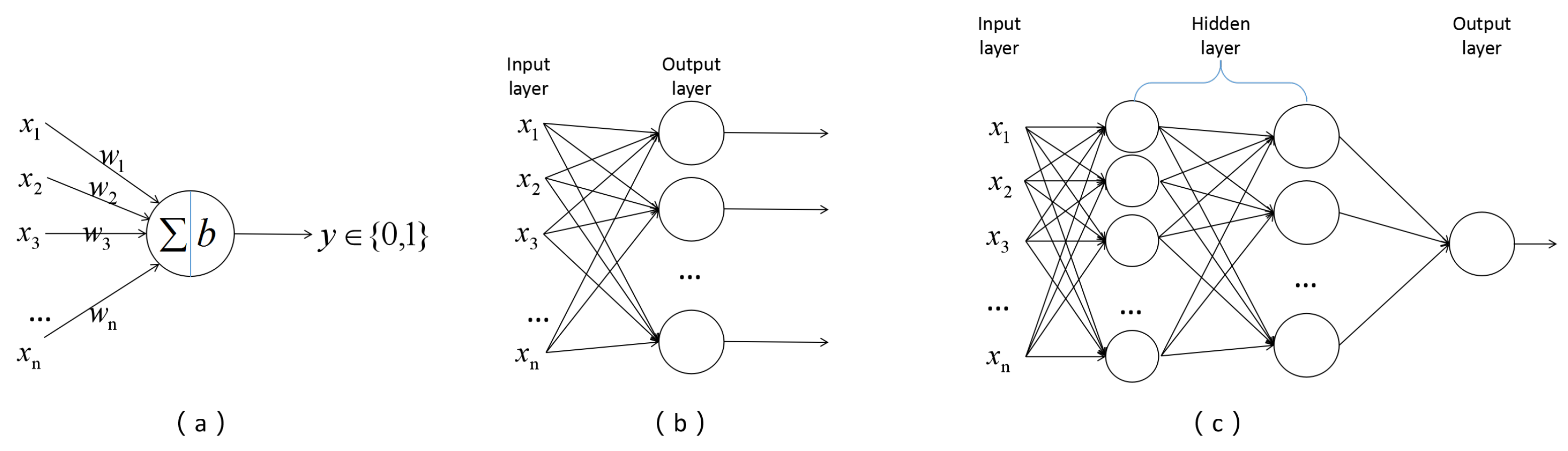
2.1. McCulloch-Pitts Neuron and Perceptron

McCulloch-Pitts neurons is a model to simulate the biological nervous system. In this model, the activation states of all other neurons are transmitted to the neuron via their own synapse, and these synapses are given strengths, called weights [26]. The strength of the synapse affects the strength of the signal, so the input is multiplied with the weight of the synapse. When all the signals reach the neuron, they are summed up to see if the sum is larger than a threshold. When the sum is truly larger than the threshold, called bias, the neuron is activated [27]. This means that McCulloch-Pitts position of whatever it is activated or not, works by the following equation, while n means the number of input, y = 1 means the neuron is activated, and vice versa:
y = 1 , ( i = 1 n w i x i b ) 0 , ( i = 1 n w i x i < b ) .
in this formula, w i means the weight of the input x i , and b means the bias in the concept of the McCulloch-Pitts neuron.
Perceptron is a typical structure in the artificial neural system, it has a simple structure but can solve problems with a convergence algorithm, and it is also proved mathematically, which can be simply explained as a combination of several McCulloch-Pitts neurons [28]. The perceptron model has improved ober time; Many-Layer Perceptron and Support Vector Machines came into the solution of most questions, they are also the advanced method for biological questions [29]. With supporting its structure, it becomes possible to solve the multi-input problems, the Figure 1 shows how McCulloch-Pitts Neuron and perceptron work. For the details of the figure, Figure 1a is the original McCulloch-Pitts Neuron model, which is a single neuron that can sum the input by their weights and calculate the output by their bias. In Figure 1b, there is a single layer perceptorn, which consists of several McCulloch-Pitts Neurons in order to solve some questions that are more complex. The Figure 1c is a multi-layer perceptron with the input layer, hidden layer and output layer and even has the ability to deal with XOR questions, which the previous one cannot.

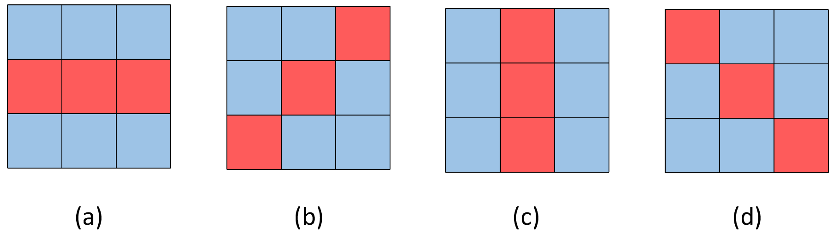
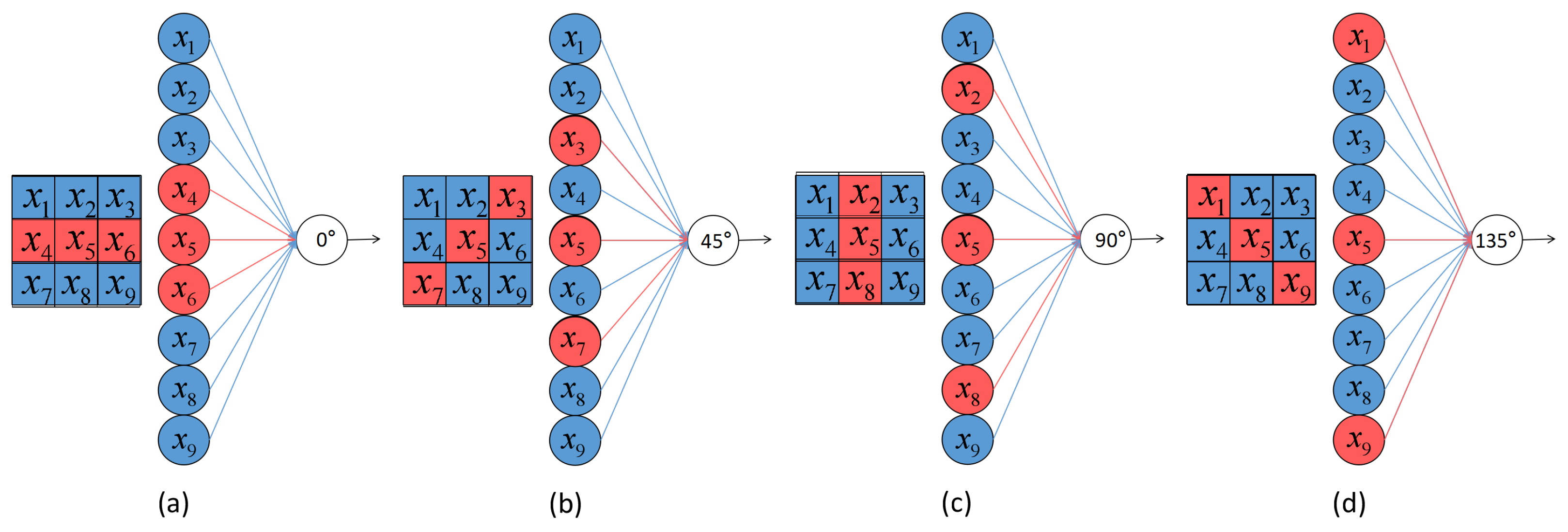
2.2. Local Edge-Orientation Detection Neuron

In Hubel and Wiesel’s research, it was found that the simple cells and complex cells are located in the V1 of the primary cortex. These kinds of cells have the ability of orientation selection when a group of light spot or thin lines are detected [8]. On the other hand, edge selective cells that only have activation to the edge of optical stimuli are found in the V1 of the primary cortex [25]. As the light spots and thin lines satisfy the feature of the edge and the location of the two kind of cells are the same, we assume that the visual orientation detection function is partly completed by such neurons and are named the local edge-orientation detection neurons. Instead of co-operating, the edge selective simple cell and the orientation selective cell is the different function of a single type of neuron. We implemented the local edge-orientation selective neurons by computer simulation. Four types of edge-orientation selective neurons are realized based on the McCulluch-Pitts neuron model, which corresponds to four orientation angles (0, 45, 90, and 135).
Each neuron is designed with a local receptive field sized 3 × 3. Additionally, within one single receptive field, four different local edge-orientation detection neurons share the same inputs from 9 photoreceptors. We designed this multi-layer perceptron in order to simplify the complex process in biology. We set each function neurons to directly receive the inputs generated by photoreceptors. When light stimulus is projected on a photoreceptor, it will be activated and generate input information 1, otherwise, it is 0 for the photoreceptors’ simulation of a single local edge-orientation cell. Moreover, to realize the function of a neuron that has edge selectivity and orientation selectivity, each input information is given different weights when transmitted to different neurons, which deciding on the neuron’s exhibitory receptive field or inhibitory receptive field. The local edge-orientation selective neuron needs the function to detect both edge and orientation. First, for the function of orientation detection, since there are only 9 pixels in a single receptive field, it can only show 4 orientations so far, so we give 4 neurons for each 9-pixel receptive field to detect its orientation. Next, to detect the edge of an object, with the theory mentioned, neurons show that both inhibitory and exhibitory position should be used, which means the weight of the inputs may be different due to the positive number for exhibitory and negative number for inhibitory, by fulfilling the following equation like a usual McCulloch-Pitts Neuron:
y = 1 , ( i = 1 9 w i x i b ) 0 , ( i = 1 9 w i x i < b ) ,
after our mathematical calculation, the weight and bias of each McCulloch-Pitts Neuron of perceptron should fulfil the inhibitory weight w i n of other pixels, which should be one fourth of exhibitory weight w e x , and the bias b is just as large or a little larger than double of the w e x . Furthermore, there should be at least 3 pixels of a straight in order to clarify the orientation and edge of the object, with the fulfilment of the equation; o means a positive number small enough that smaller than the absolute value of inhibitory weight in order to simplify the situation of the specific one to avoid, which is activated when 4 of the pixels other than the orientation ones can be detected but not the edge, theoretically:
y = 1 , ( i = 1 3 w e x x i + j = 1 6 w i n x i b ) 0 , ( i = 1 3 w e x x i + j = 1 6 w i n x i < b ) ( 2 w e x = 8 w i n = b o ) .
For example, when we give the w e x value 1, the w i n is valued −0.25; o can be a positive number below 0.25, but theory of signal processing tells us that noise is inevitable and the input cannot always keep 0 and 1, so we give o the value of 0.125 to avoid it. Finally, the threshold, b, obtains the value of 2.125. Each orientation follows the Figure 2, such as a McCulloch-Pitts Neuron (here, we use the one of 0 degree as an example).
This McCulloch-Pitts Neuron works by the equation:
y = 1 , ( i = 1 3 x i j = 1 6 0.25 x i 2.125 ) 0 , ( i = 1 3 x i j = 1 6 0.25 x i < 2.125 ) ,
just like Figure 3, while the red pixels have exhibitory weight and the blue ones have inhibitory weight, only in the situation of the sum by weight over the bias, the edge-orientation detection neuron becomes activated. Because Figure 3a is a 0-degree detection neuron, the pixels including the central one combined as 0-degree is with the exhibitory weight, so the Figure 3b–d is of the degree of 45, 90 and 135.
Figure 4 shows how this kind of neurons works, desperately.
For further illustration, especially the specific position that the summary of inputs with weight is close to the bias, we show a situation in Figure 5 in order to explain how we sort these performances of receptive field out. In Figure 5a, 6 pixels are detected with light stimuli, and it is easy for our eyes to distinguish it with the angles or the internal part of objects, and also it is simply regarded as an edge of a 0 degree thick object, or the bottom of an object of another degree contributing little for global orientation detection, at least as a 2-pixel thickness thin object. So, as the Figure 5b, it can be regarded as a possibility of a thick irregular object or a thin one. However, when 7 pixels is detected with light stimuli, our eyes are confused as to our edge-orientation detection neuron, which proves our theory laterally. In the Figure 5c,d, it is possible to be inside a thick object with irregular form, or more possible for a regular thin object, at the string, which is very close to the edge instead off the edge. Consequently, we choose the boundary of our edge-orientation detection neuron as a 6-pixel image other than a 7-pixel one.
In the simplified experiment in Figure 6, we use the 0-degree edge-orientation neuron shown in Figure 6a as a sample, and a irregular object colored yellow in Figure 6b is given to be detected. Giving a specialize weight 1 for exhibitory parts, the inhibitory ones obtain −0.25 here for calculating in the experiment. The o, however, due to the theory of signal processing, signal may changed to noise in some cases, we give it the value of 0.125 to avoid noise that may occupy the experiments but still fulfil the conditions before, just fitting the example we have given. When our 0-degree edge-orientation neuron detects its edge and the orientation of this part fit the neuron, such as in Figure 6c, it becomes activated. When it detects the edge but a different degree, it will never be activated like Figure 6d. If there is no edge of the object whatever, it is a background like Figure 6e or the inside of object like Figure 6f; it keeps being inactivated. In our theory, the neurons of other degrees work at the same mechanism.
This result is just the same with a biological experiment, in which these kinds of neurons are discovered in the V1 cells of the primary cortex, and become exhibitory when the edge of objects is detected or is in an inhibitory position in other positions, so this mechanism is proved by biologist [25]. As a result, these kinds of perceptrons with the 9-pixel photoreceptors inputs and 4 edge-orientation neurons can solve the local orientation detection and edge detection problems. The inhibitory and exhibitory regions’ arrangement of four edge-orientation detection neurons are shown in Figure 7 that have the same rules with the Equation (3), different neurons prefer different regions of inputs and obtain their own weights by their regions placed in receptive field; the red strings represent the exhibitory inputs to the neurons they correspond with when objects were detected, while the blue strings represent the inhibitory inputs. Finally, all of their sums will get a comparison with the bias of four neurons to calculate the orientation.
By analyzing the individual inputs in the receptive field of the 9 pixels and using a perceptron, a local edge orientation detection model can be obtained. As the neurons in primary cortex have the function of edge selectivity, it can detect the orientation of an object by its edge, as long as the function is of orientation detection. Due to its function, we named it the edge-orientation detection neuron in the following section of this paper.

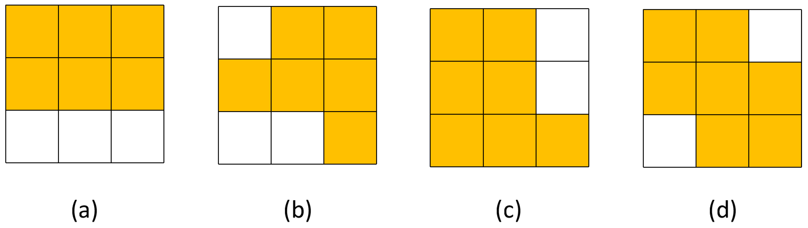
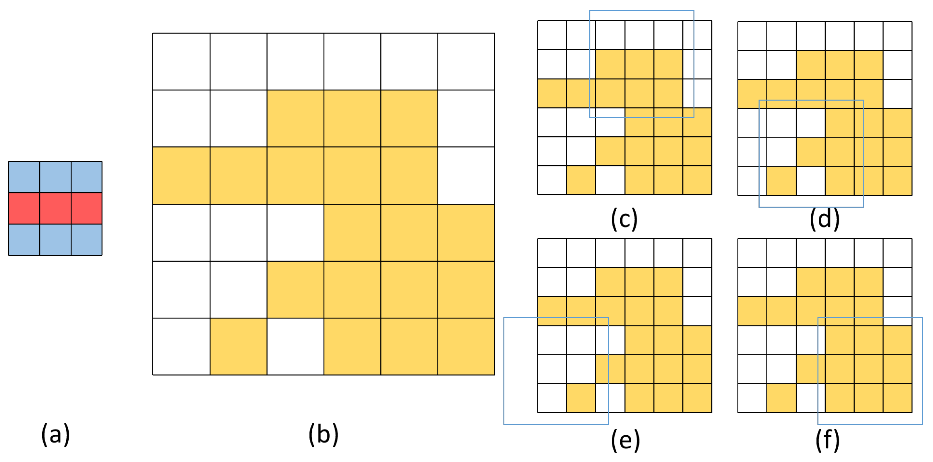
2.3. Global Edge-Orientation Detection Neuron
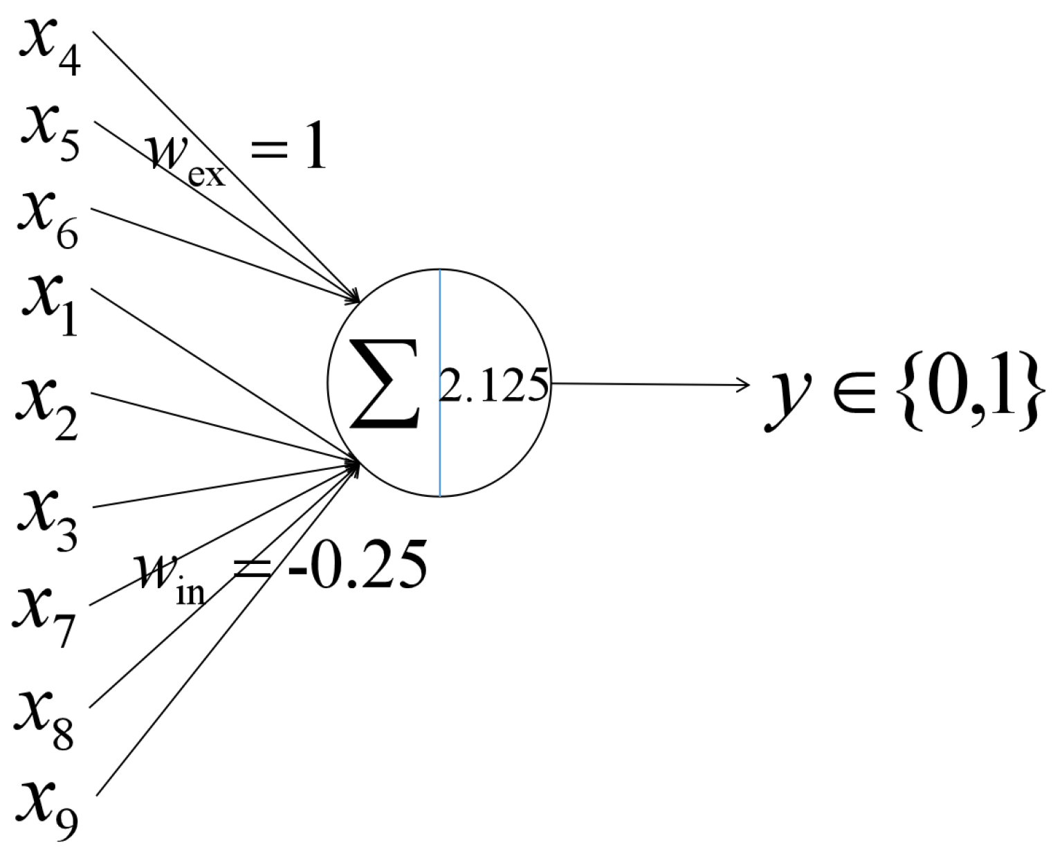
After our experiment, we find that these edge-orientation detection neurons can be used in global orientation detection as well. According to the methodology of obtaining global information from the local, we implemented an artificial visual system based on the edge-orientation selective neuron. For the orientation task on an object within an image, we first divide the image into several local regions and then use edge-orientation detection neurons to extract all local information. Finally, we obtain the global orientation according to the activation situation of function neurons in every local region. The global orientation corresponds to the type of function neuron with the most activation. However, the splendid outputs of edge-orientation cannot be calculated with no specific cells. It was found that the simple cells and complex cells located in the V1 cells of the primary cortex have orientation selection but the response of a group of light spot or thin lines is of the simple cells; the complex cells have the function to align the output of a large number [8]. Although the mechanism of how it concretely works is not clear, the results of the simulation show that adding and comparing the number of the outputs is very close to it [30]. Furthermore, research demonstrates that the retina can conduct the global detection by summing the output of the local neurons, and comparing the differences inside, in order to conduct complex actions [31]. In another word, a sumpooling layer is needed after the output part of a local edge-orientation detection neuron to correct which angle is indeed when several detection results appear. A sumpooling layer is to add up all the inputs, and the output is the summary of tthe inputs, as shown in Figure 8.
A two-dimensional global direction detection system based on a perceptron is shown in this section. In the input layer, the output of a photoreceptor is equal to the input value, where a photoreceptor receives light with a corresponding input value of 1 and 0 otherwise. The structure of the orientation detection artificial visual system and its working flow on a 4 × 4 image is shown in Figure 9. With each pixel as the center of the local receptive field, 4 local regions can be divided. For the light stimuli within the 4 × 4 region, 4 photoreceptors receive the corresponding information. In the figure, photoreceptors that receive light are colored yellow. Otherwise, they are represented colorless. After each local receptive field, four different edge-orientation detection neurons are connected. Therefore, 16 neurons are needed to extract all local orientation information. Exhibitory edge-orientation selective neurons are colored red, while inhibitory edge-orientation selective neurons are colored blue. There is a sumpooling layer after the output part, as it is explained before, it will sum up how many pixels are detected as a specific degree. Following our detection method, the global orientation can be inferred from the activation of all function neurons and the most activated neuron type corresponding to the orientation of the object.
The bar graph in Figure 10 shows the number of activated neurons of the four orientations of edge-orientation selective neurons. According to our mechanism of the global edge-orientation detection neuron, we use a sumpooling layer to decide which orientation is the final one by the outputs of it. From the histogram of the sumpooling result, we know that the 45 degree selective neurons are the most numerous activated neurons, so the detection result is that the object is oriented at 45 degree, which is consistent with the observations by the real visual system that we have seen.
Consequently, these regulations of our edge-orientation neurons should follow:
(1)
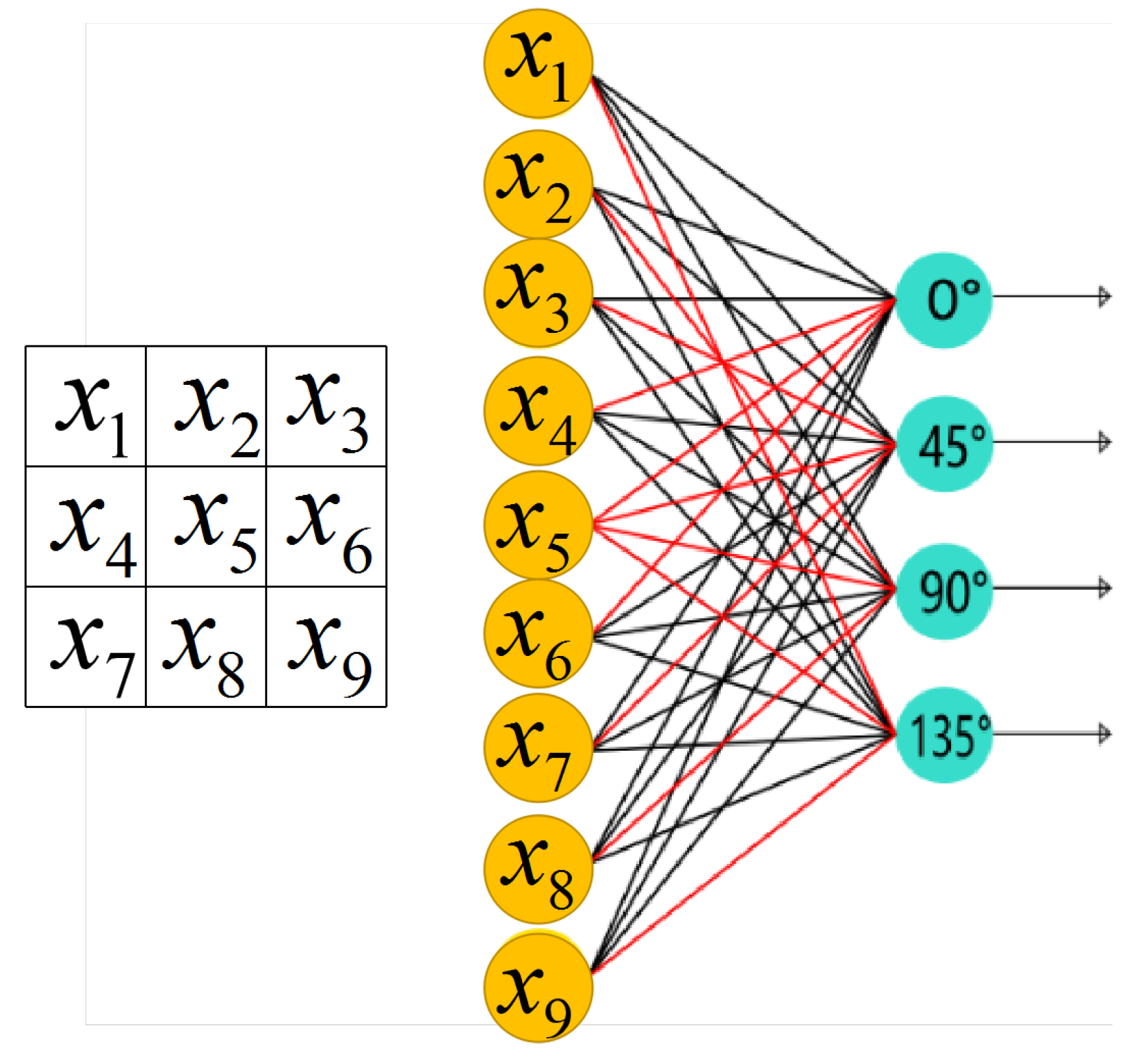
Each neuron receives 9 specific inputs from the photoreceptors they are in charge of, and obtain the weight depending on the characteristics of the distribution of the different inputs.
(2)
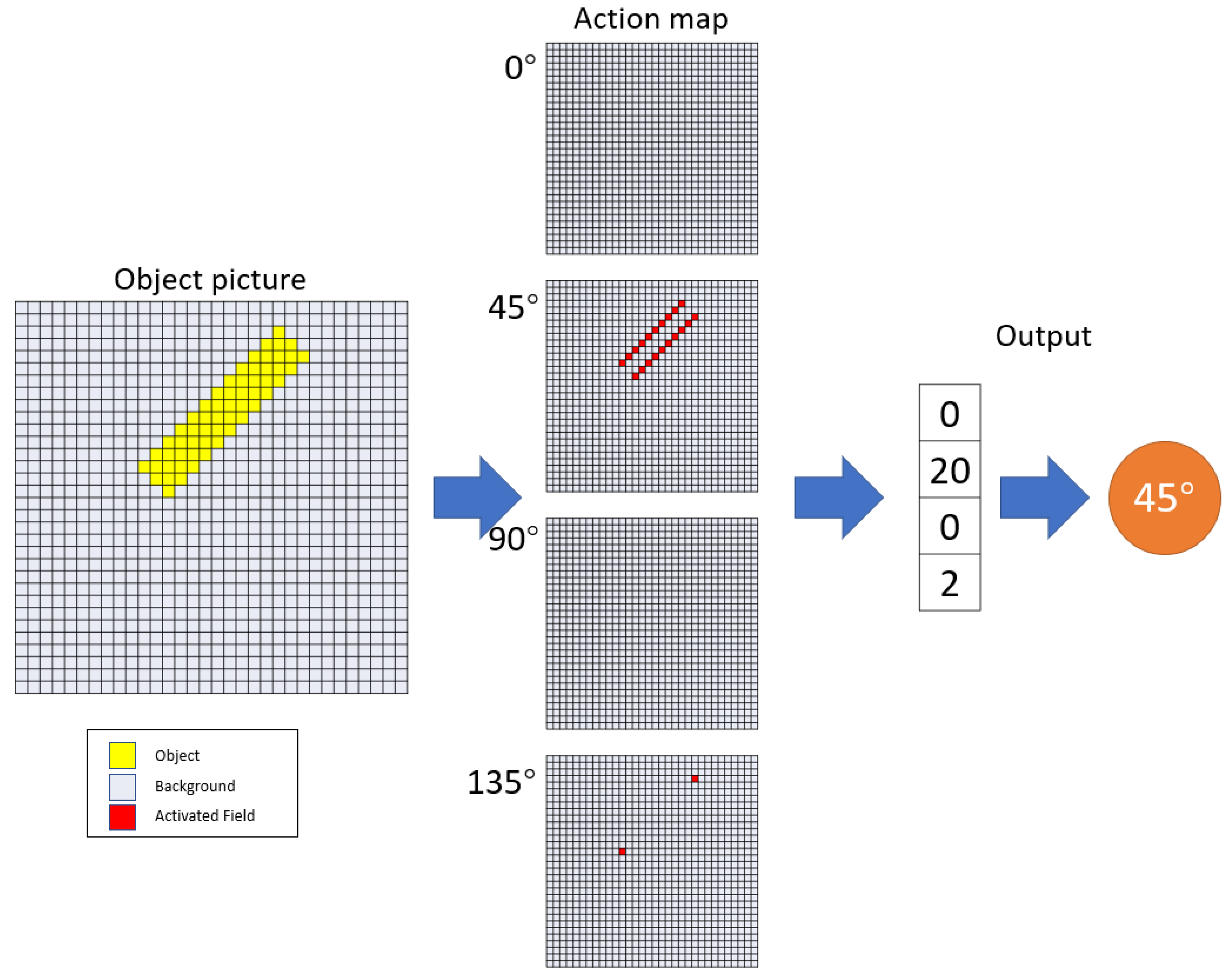
In the local receptive field, four neurons can be defined as four different orientation and edge selective neurons, in order to detect the orientation of the objects’ edge.
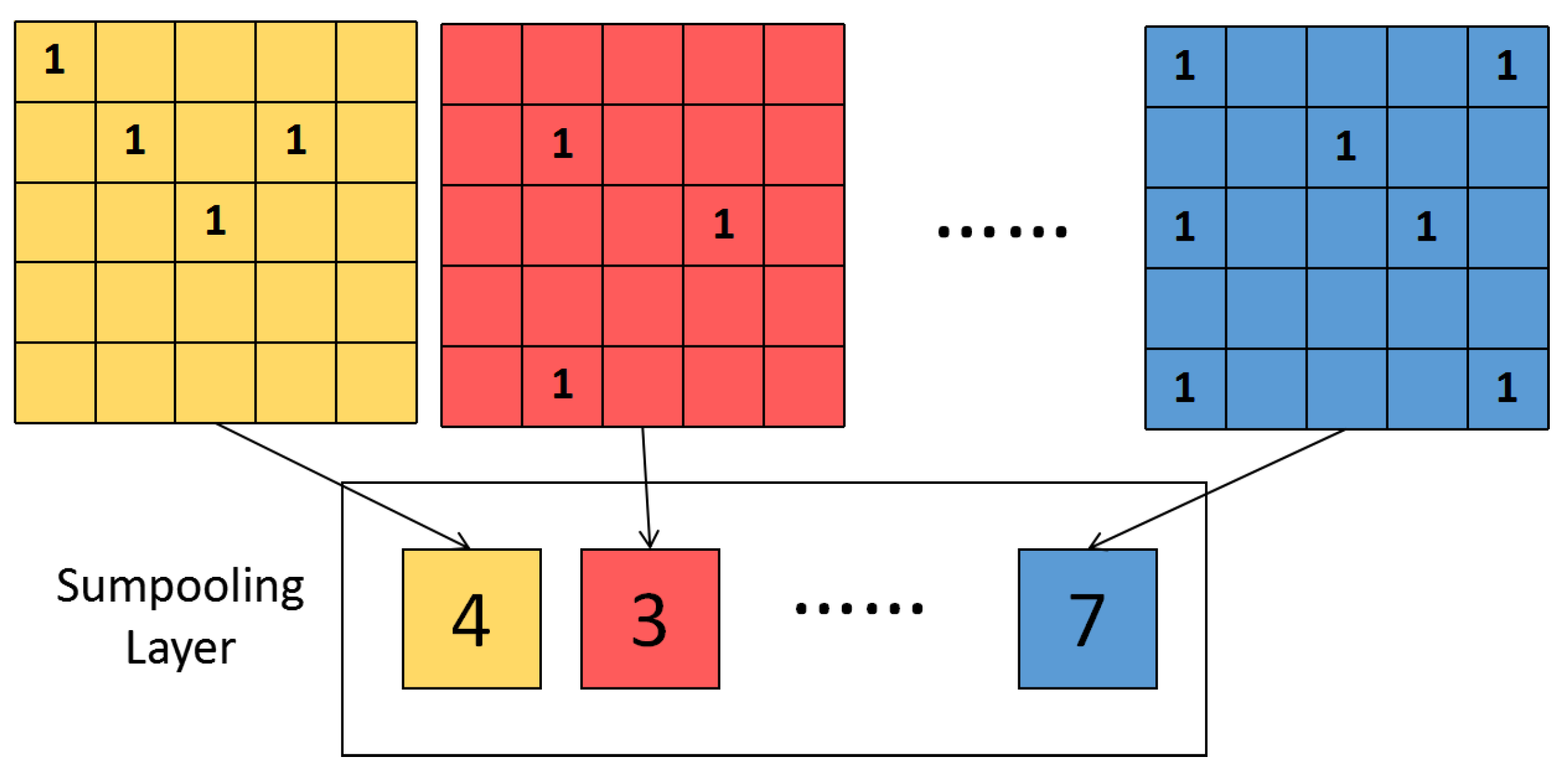
(3)
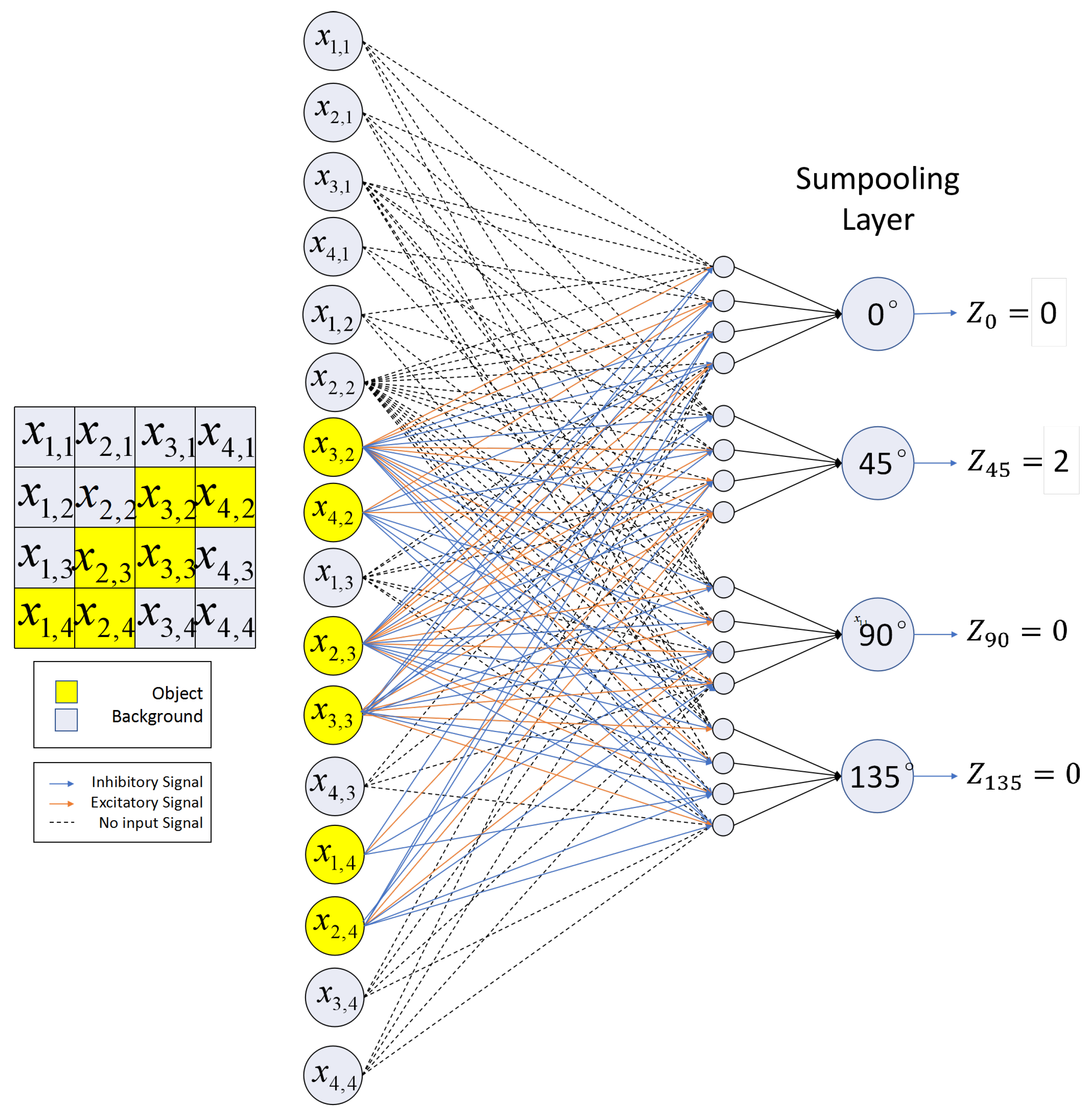
After the output layer of the four selective neurons, we set up four ladders as a sumpooling layer, and the output comes from former steps, which calculates the sum of the effective outputs, and then, counts the number of such neurons activated.
(4)
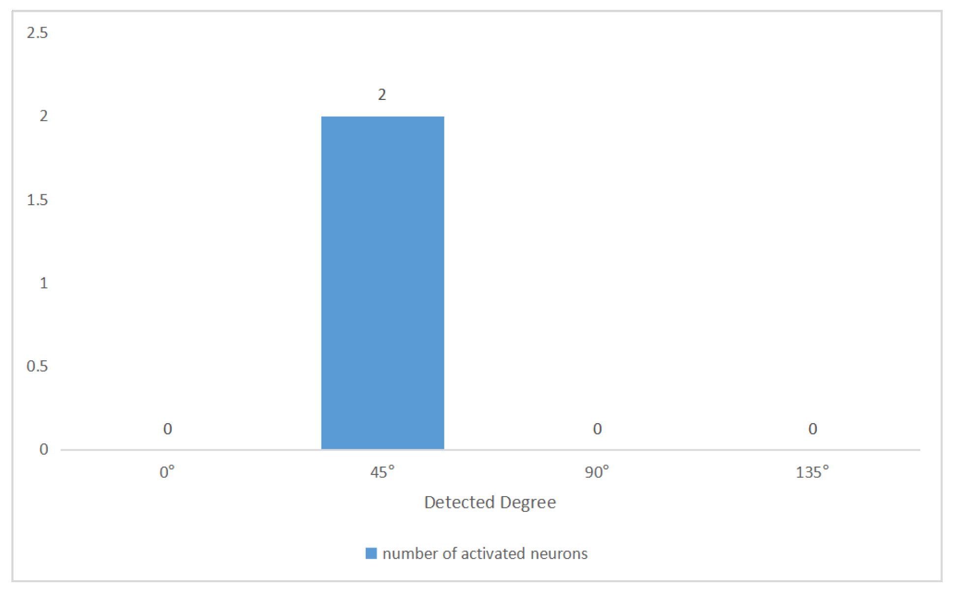
A kind of specialized cell will do a comparison of the number of 4 kinds of outputs, as the function of complex cells in Hubel’s theory, and decide the final output of the orientation detection result.
For the objects for which orientations are given in following experiment, we use edge-orientation detection neurons to detect all local orientations, derive their global orientation and determine it by a contrasting algorithm based on the number of activated neurons.

3. Simulation Results

To validate the global orientation detection mechanism of the edge-orientation selective neuron, we implemented this mechanism and the artificial visual system based on the previous illustrated mechanism by computer simulation. Performance of this artificial visual system is tested on binary image data sets. We first generated an original binary image data set consisting of 40,000 noiseless images, which are sized 32 × 32. These images are created by our original program that first builds a 32 × 32 pixels white image with the input 0. Since there are only 4 orientation degrees needed to be detected, we designed objects in regular shapes (for example, a 32-pixel object can be designed as 4 × 8 or 2 × 16 in 0 or 90 degree and 10 + 11 + 11 for 45 or 135 degree) and then placed them anywhere that has enough space for them. Each image is generated with a small object (size of 4 pixels, 8 pixels, 12 pixels, or 16 pixels since the smallest object our artificial visual system can detect is the 3-pixel one) or a large object (size of 32 pixels or above since an object over 32 pixel has the ability to fulfil every part of the image) with random orientation.
For an image sized 32 × 32, taking each pixel point as the center of the local receptive field, 1024 (32 × 32) local areas could be divided out. Thus, a total of 4096 (4 × 1024) neurons need to be involved in a process of orientation detection. To visualize this mechanism, we take an example in Figure 11 and show its action map.
The feasibility of the artificial visual system is first evaluated on 20,000 noiseless images. The detection results on clean images are given in Table 1. All objects’ orientation could be correctly recognized no matter the object size. The global orientation detection mechanism of edge-orientation selective neurons and the mechanism-based artificial visual system are feasible.
As mentioned in the previous article, due to the wide availability of orientation detection, there are many orientation detection methods now. However, the most widely used is the CNN-based orientation detection and evolved EfN-based orientation detection, which has the ability to learn and has the highest recognized accuracy. This means if our artificial visual system has a higher accuracy than these methods, it will have the most believable result on the specific positions. That means it is important to take these methods into comparison to prove how correct is an artificial visual system.
So, we further confirmed the artificial visual system’s noise immunity and compared it with the classical CNN. Figure 12 shows the structure of the utilized CNN model. Four 3 × 3 filters were used in the convolution layer, and 2 × 2 maxpooling was used in the pooling layer. The output size of the first affine layer was 256, and the last layer ended up with outputting the confidence of four orientation angles. Adam was chosen as the training optimizer. Moreover, in order to ensure enough data for learning, 40,000 pictures are randomly selected from an original data set as the training set; some of them are probably to be repeated, since there are limited permutations for objects with a given size and degree (this is also a weakness of the CNN we mentioned), and then 10,000 pictures are randomly selected from the remaining data as the test set. Within 50 training epochs, choose the model parameters as final parameters when the model has the highest validation accuracy.
For further comparison, we also took EfN, which is another method that has high accuracy, into consideration. As it is well known, EfN has a complex structure and needs a lot of blocks to run. We used EfN to provide proof to show our artificial visual system’s accuracy. In the Figure 13, we showed the standard structure of EfN, and the data set is the same with CNN, because of the needs of training for both of them. It is truly proved that EfN also has the ability to detect the orientation of the objects correctly, and both groups of the objects demonstrated a high accuracy of 100.00%.
To match various possible noise conditions, four types of noise were separately utilized in generating the noise image data: object noise, edge noise, background noise, and random noise.
For object noise type, which means ‘noise on the object’, 1, 2, 4, 8, or 16 pixels of the object were changed into noise (pixel value changes from 1 to 0). Figure 14 illustrates an example of image data with object noise.
Table 2 gives the detection results of artificial visual system, CNN and EfN on the object noise data. Artificial visual system shows a better noise immunity than CNN. It is clear that noise in the objects can influence the result of the local neuron of traditional artificial visual system without using the inhibitory mechanism because of the change of some 9-pixel parts in the whole picture, and CNN and EfN can also be confused by the noise that cover the object and lead to a wrong result, which can lead to a different conclusion of the orientation. In fact, the result of the experiment shows that the edge-orientation neuron can keep its accuracy in a high level when it meets this kind of noise.
For edge noise type, which means ‘noise on the edge of the object’, 1, 2, 4, 8, or 16 pixels around the object were changed into noise (pixel value changes from 0 to 1). An example of image data with edge noise are shown in Figure 15.
According to Table 3, although the accuracy of our edge orientation detection model tends to decrease significantly as the amount of noise in contact with the object increases, it is still much slower than the accuracy of EfN and CNN. This is because the noise on the edge of object can easily influence the orientation of the “edge” of the object in the picture. As a neuron which needs to detect the orientation of edge, our artificial visual system may reduce the accuracy because of this kind of noise. Frankly, our artificial visual system accuracy is truly low down in a small level, because the edge can only change a little part of them, as well as the CNN is seriously misled by it.
For background noise type, which means ‘noise on the background’, different proportions of the background pixels were changed into noise (pixel value changes from 0 to 1). An example of image data with background noise is given in Figure 16.
The results are given in Table 4. It is obvious that CNN’s learning ability is limited in more chaotic noise conditions. The edge orientation detection model still has the ability to accurately recognize object orientation and the anti-noise performance is acceptable, especially on large objects. Chaotic noise will no doubt influence the judgement of CNN and EfN because they are designed to learn information by all the important parts of a picture. However, our artificial visual system can easily detect the orientation, as it is designed to detect the orientation information most necessary unless too many noises of the pixel combine into a whole object.
These experiments used Google-Colaboratory’s device. To demonstrate that our artificial visual system can save the cost not only by duration, but also by the calculation ability of devices, we used CPU to calculate our artificial visual system, and GPU for CNN and EfN, since it is well known that both these systems take much more time when calculated by CPU than GPU. The Google-Colaboratory’s paid account can use efficient GPU randomly, but we chose the same GPU, which works the fastest in the experiments. Since the images are all consist of binary pixels and have the same number, they took a similar time to calculate the orientation information. As a result, we chose to demonstrate the duration by the average of all the experiments, which means each experiment for 10 times (40 times totally).
In order to compare the duration of all of three orientation detection system, we made Table 5 to show the differences between these three systems.
In summary, our proposed edge orientation detection mechanism is reliable. This model also fits the variation well in the recognition ability of organisms for objects, considering the variation in the recognition efficiency of the noise generated on the edges of the objects, especially in such binarized images. That is, this model can be interpreted as a good simulation of the visual system of the creature while having a strong ability of anti-noise.
The methods used for comparison, CNN and EfN, show a high accuracy when there is no noise. However, when the noise occupied the images, the accuracy descended immediately. Although the accuracy of EfN fell much more slowly than CNN, it is truly influenced dramatically by the noise. In our consideration, the reason of it is that both CNN and EfN obtain the feature of a whole image instead of the object. When too much noises appear, the feature of the object stays but one of the whole pictures does not; this is why our artificial visual system has a better result. Further more, the learning algorithm also has to face the problem of overfitting, that is why EfN and CNN become even lower when they detect the images with background noise.
The mechanism-based artificial visual system has excellent performance on clean data. In addition, the artificial visual system is a direct computer simulation of the biological visual system and eliminates the learning costs because it has no learning process. In comparison with CNN and EfN, the detection system is more feasible for object orientation angles against CNN and EfN, and the model has good immunity on noise data, especially noise inside the object or a large amount of random background noise. Therefore, we conclude that the artificial visual system has a high recognition accuracy, lower computational and learning costs compared to traditional methods, and has better noise immunity.

4. Conclusions

In this paper, we proposed a novel two-dimensional global orientation detection mechanism based on the neurons in the primary cortex of the human visual system. We assumed that there are neurons which can only detect a specific orientation of the objects’ edge, and each neuron is only responsible for a local area.
The global information is obtained from the activation position of different types of neurons. We use the present theory in the field of retina and cortex research, and provide the global edge-orientation detection neuron a sumpooling layer to decide the final result of the orientation detection from those numerous outputs. The final detection result depends on the type of neurons that are most activated. These theories are completely based on the biological experiments and hypothesis of biologists, which makes our research more convincing on physiology. We implemented an orientation detection system based on the mechanism through computer simulations and evaluated its recognition performance on a large number of objects with different orientations, positions, sizes, and noise types. This artificial visual system shows better detection accuracy and noise immunity than CNN-based and EfN-based image technological orientation detection systems, and it significantly saves time and learning costs, which is obviously proved in our experiments.
As it is simple to calculate, it can be taken into use soon when a binary image needs to be detected. Their accuracy makes it more correct than the present method, and shows the possibility of the bionic artificial visual system. It also has the merit mentioned several times previously that it takes less time than EfN to calculate the detailed features in the image due to the parameters we have given by the theory of biological basic, and the prolix learning steps and the costs were prepared in advance. Calculation units that CNN needs for sorting and classifying is also cut down.
The success of the proposed mechanism provided a possible solution for explaining global orientation detection. Due to the necessity of learning for CNN and EfN and the possible lack of database, our artificial visual system can be used for some positions that has little data for learning, just like the pathology figures, geography measures and other situations needing orientation detection of binary images, which are also detected by our artificial visual system. For example, it is verified that pathology figures operated into binary images can be detected as our four orientations close to the correct angles, the usage of our artificial visual system can be proved when developed.Since image orientation detection’s wide usage, our research has a lot of applications that can be predicted. By researching this mechanism in depth, it is possible to enlarge the receptive field into 5 × 5 or 3 × 5 for the further research of this mechanism with more degree to detect. On the other hand, by adding some biological research results, we can do grayscale image orientation detection and colored image orientation detection in the future. This discovery not only proposes an extraordinary way to solve orientation detection questions in the analysis of images, but also shows the possibility in image processing that a biological based visual system can be used for other scientific areas. If it can be demonstrated in biological neural structures, it will provide a strong guide to our understanding of the human brain orientation detection mechanism and help construct the biological structure of the visual system. As a result, both computer science and biological brain science can see the importance of this model commonly.

Author Contributions

Conceptualization, B.L., T.C. and Y.T.; methodology, T.C.; software, T.C. and B.L.; validation, T.C.; formal analysis, T.C.; investigation, B.L. and T.C.; data curation, B.L.; writing—original draft preparation, T.C.; writing—review and editing, Y.T.; visualization, T.C. All authors have read and agreed to the published version of the manuscript.

Funding

This research received no external funding.

Data Availability Statement

Not applicable.

Conflicts of Interest

The authors declare no conflict of interest.

References

  1. Todo, Y.; Tang, Z.; Todo, H.; Ji, J.; Yamashita, K. Neurons with multiplicative interactions of nonlinear synapses. Int. J. Neural Syst. 2019, 29, 1950012. [Google Scholar] [CrossRef] [PubMed]
  2. Medina, J. Brain Rules: 12 Principles for Surviving and Thriving at Work, Home, and School; ReadHowYouWant: Sydney, Australia, 2011. [Google Scholar]
  3. Fiske, S.T.; Taylor, S.E. Social Cognition; Mcgraw-Hill Book Company: New York, NY, USA, 1991. [Google Scholar]
  4. Vanston, J.E.; Strother, L. Sex differences in the human visual system. J. Neurosci. Res. 2017, 95, 617–625. [Google Scholar] [CrossRef] [PubMed]
  5. Namboodiri, V.M.K.; Huertas, M.A.; Monk, K.J.; Shouval, H.Z.; Shuler, M.G.H. Visually cued action timing in the primary visual cortex. Neuron 2015, 86, 319–330. [Google Scholar] [CrossRef] [PubMed] [Green Version]
  6. Hubel, D.H.; Wiesel, T.N. Receptive fields, binocular interaction and functional architecture in the cat’s visual cortex. J. Physiol. 1962, 160, 106. [Google Scholar] [CrossRef] [PubMed]
  7. Hubel, D.H.; Wiesel, T.N. Shape and arrangement of columns in cat’s striate cortex. J. Physiol. 1963, 165, 559. [Google Scholar] [CrossRef] [PubMed] [Green Version]
  8. Hubel, D.H.; Wiesel, T.N. Receptive fields of single neurones in the cat’s striate cortex. J. Physiol. 1959, 148, 574. [Google Scholar] [CrossRef] [PubMed]
  9. Hubel, D.H. Exploration of the primary visual cortex, 1955–1978. Nature 1982, 299, 515–524. [Google Scholar] [CrossRef] [PubMed]
  10. Hubel, D.H.; Wiesel, T.N. Receptive fields and functional architecture of monkey striate cortex. J. Physiol. 1968, 195, 215–243. [Google Scholar] [CrossRef] [PubMed]
  11. Baylor, D.; Hodgkin, A.; Lamb, T. The electrical response of turtle cones to flashes and steps of light. J. Physiol. 1974, 242, 685–727. [Google Scholar] [CrossRef] [PubMed] [Green Version]
  12. Vallerga, S.; Covacci, R.; Pottala, E. Artificial cone responses: A computer-driven hardware model. Vis. Res. 1980, 20, 453–457. [Google Scholar] [CrossRef] [PubMed]
  13. Kwon, S.M.; Cho, S.W.; Kim, M.; Heo, J.S.; Kim, Y.H.; Park, S.K. Environment-adaptable artificial visual perception behaviors using a light-adjustable optoelectronic neuromorphic device array. Adv. Mater. 2019, 31, 1906433. [Google Scholar] [CrossRef] [PubMed]
  14. Kadota, T.; Mizote, M.; Kadota, K. Synaptic spinules attendant on post-tetanic potentiation in cat sympathetic ganglion. Proc. Jpn. Acad. Ser. B 1996, 72, 48–51. [Google Scholar] [CrossRef] [Green Version]
  15. Baxter, L.C.; Coggins, J.M. Supervised pixel classification using a feature space derived from an artificial visual system. In Proceedings of the Intelligent Robots and Computer Vision IX: Algorithms and Techniques, SPIE, Orlando, FL, USA, 2–4 April 1991; Volume 1381, pp. 459–469. [Google Scholar]
  16. Li, B.; Todo, Y.; Tang, Z. The Mechanism of Orientation Detection Based on Local Orientation-Selective Neuron. In Proceedings of the 2021 6th International Conference on Computational Intelligence and Applications (ICCIA), Xiamen, China, 11–13 June2021; pp. 195–199. [Google Scholar]
  17. Francis, P.J.; Wills, B.J. Introduction to principal components analysis. arXiv 1999, arXiv:astro-ph/9905079. [Google Scholar]
  18. Veeser, S.; Cumming, D. Object Position and Orientation Detection System. U.S. Patent 9,536,163, 3 January 2017. [Google Scholar]
  19. Knutsson, H. Filtering and Reconstruction in Image Processing. Ph.D. Thesis, Linköping University Electronic Press, The Institute of Technology at Linköping University, Linköping, Sweden, 1982. [Google Scholar]
  20. Veeser, S.; Cumming, D. Learning orientation-estimation convolutional neural network for building detection in optical remote sensing image. In Proceedings of the 2018 Digital Image Computing: Techniques and Applications (DICTA), Canberra, Australia, 10–13 December 2018; pp. 1–8. [Google Scholar]
  21. Tan, M.; Le, Q. Efficientnet: Rethinking model scaling for convolutional neural networks. In Proceedings of the International Conference on Machine Learning, Long Beach, CA, USA, 9–15 June 2019; pp. 6105–6114. [Google Scholar]
  22. Burr, D.; Thompson, P. Motion psychophysics: 1985–2010. Vis. Res. 2011, 51, 1431–1456. [Google Scholar] [CrossRef] [PubMed] [Green Version]
  23. Li, B.; Todo, Y.; Tang, Z. Artificial Visual System for Orientation Detection Based on Hubel–Wiesel Model. Brain Sci. 2022, 12, 470. [Google Scholar] [CrossRef] [PubMed]
  24. Zhu, M.M.; Xu, Y.L.; Ma, H.Q. Edge Detection Based On the Characteristic of Primary Visual Cortex Cells. J. Phys. Conf. Ser. 2018, 960, 012052. [Google Scholar] [CrossRef]
  25. Kandel, E.R.; Schwartz, J.H.; Jessell, T.M.; Siegelbaum, S.; Hudspeth, A.J.; Mack, S.; Mack, S. Principles of Neural Science; McGraw-Hill: New York, NY, USA, 2000; Volume 4. [Google Scholar]
  26. McCulloch, W.S.; Pitts, W. A logical calculus of the ideas immanent in nervous activity. Bull. Math. Biophys. 1943, 5, 115–133. [Google Scholar] [CrossRef]
  27. Collobert, R.; Bengio, S. Links between perceptrons, MLPs and SVMs. In Proceedings of the Twenty-First International Conference on Machine Learning, Banff, AB, Canada, 4–8 July 2004; p. 23. [Google Scholar]
  28. Minsky, M.; Papert, S. An introduction to computational geometry. Camb. Tiass HIT 1969, 479, 480. [Google Scholar]
  29. Rosenblatt, F. Principles of Neurodynamics. Perceptrons and the Theory of Brain Mechanisms; Technical Report; Cornell Aeronautical Lab Inc.: Buffalo, NY, USA, 1961. [Google Scholar]
  30. Antinucci, P.; Suleyman, O.; Monfries, C.; Hindges, R. Neural mechanisms generating orientation selectivity in the retina. Curr. Biol. 2016, 26, 1802–1815. [Google Scholar] [CrossRef] [PubMed] [Green Version]
  31. Henning, M.; Ramos-Traslosheros, G.; Gür, B.; Silies, M. Populations of local direction–selective cells encode global motion patterns generated by self-motion. Sci. Adv. 2022, 8, eabi7112. [Google Scholar] [CrossRef] [PubMed]
Figure 1. (a) A McCulloch-Pitts Neuron model with its inputs, weights, bias and output; (b) A perceptron and its input layer and output layer; (c) A multi-layer perceptron that has input layer, hidden layers and output layer.
Electronics 11 03946 g001
Figure 2. An example of given value of weight and bias.
Electronics 11 03946 g002
Figure 3. Weight of different pixels in the receptive field of a single neuron. (a) 0-degree neuron; (b) 45-degree neuron; (c) 90-degree neuron; (d) 135-degree neuron.
Electronics 11 03946 g003
Figure 4. Weight of different pixels in the receptive field of a single neuron and shown as MP neurons. (a) 0-degree neuron; (b) 45-degree neuron; (c) 90-degree neuron; (d) 135-degree neuron.
Electronics 11 03946 g004
Figure 5. Some special situation of a single receptive field. (a,b) 6 pixels detected image; (c,d) 7 pixels detected image.
Electronics 11 03946 g005
Figure 6. An example of how a local 0-degree edge-orientation neuron detects an object: (a) a local 0-degree edge-orientation neuron; (b) a random irregular object; (c) a 9-pixel receptive field on the edge of the object with the same degree as the local edge-orientation neuron; (d) a 9-pixel receptive field on the edge of the object with the different degrees with the local edge-orientation neuron; (e) a 9-pixel receptive field on the background; (f) a 9-pixel receptive field inside the object.
Electronics 11 03946 g006
Figure 7. A local orientation neuron mechanism shown as a multi-layer perceptron.
Electronics 11 03946 g007
Figure 8. An example of a sumpooling layer.
Electronics 11 03946 g008
Figure 9. A global orientation detection of an example picture.
Electronics 11 03946 g009
Figure 10. Activated neuron in Figure 9.
Electronics 11 03946 g010
Figure 11. A total of 56 pixels, 45 degree and action maps.
Electronics 11 03946 g011
Figure 12. Structure of CNN.
Electronics 11 03946 g012
Figure 13. Structure of EfN.
Electronics 11 03946 g013
Figure 14. 50pixel, 90° 16pixel object noise.
Electronics 11 03946 g014
Figure 15. A total of 75 pixel, 0° 16pixel edge noise.
Electronics 11 03946 g015
Figure 16. A total of 30 pixel, 0° 20% background noise.
Electronics 11 03946 g016
Table 1. Noise-free accuracy of artificial visual system.
Object SizeAccurate NumberNumber of PicturesAccuracy
Small objects 110,00010,000100.00%
Large objects 210,00010,000100.00%
1 Objects of 4, 8, 16 pixels. 2 Objects of 32 or more pixels.
Table 2. Object noise accuracy.
Object SizeNoise SizeEOAVS 1CNNEfN
Small size2199.57%72.85%69.58%
288.75%66.00%67.83%
Large size31100.00%100.00%100.00%
2100.00%99.95%97.66%
499.70%99.40%94.11%
896.66%77.40%83.92%
1676.23%59.60%73.23%
1 Edge and orientation detection artificial visual system. 2 Objects of 4, 8, 16 pixels. 3 Objects of 32 or more pixels.
Table 3. Edge noise accuracy.
Object SizeNoise SizeEOAVS 1CNNEfN
Small size2197.70%98.35%95.03%
293.32%86.05%88.47%
486.77%71.00%79.17%
876.08%49.85%59.53%
Large size31100.00%100.00%100.00%
2100.00%99.94%96.90%
499.28%99.20%88.80%
896.14%77.70%86.43%
1689.83%61.60%82.85%
1 Edge and orientation detection artificial visual system. 2 Objects of 4, 8, 16 pixels. 3 Objects of 32 or more pixels.
Table 4. Background noise accuracy.
Object SizeNoise Percentage 1EOAVS 2CNNEfN
Small size35%91.41%45.75%34.07%
10%77.05%33.65%29.80%
15%63.51%31.70%28.20%
20%52.34%37.95%24.20%
Large size45%99.87%48.95%40.63%
10%98.51%48.70%38.52%
15%93.58%48.40%37.97%
20%82.17%36.20%35.44%
1 Size of noise equals the whole picture size multiplies the percentage. 2 Edge and orientation detection artificial visual system. 3 Objects of 4, 8, 16 pixels. 4 Objects of 32 or more pixels.
Table 5. Device and duration of orientation detection system.
Orientation Detection SystemDeviceTypeDuration
EOAVS 1CPUIntel(R) Xeon(R) CPU @ 2.20 GHz1 min 17 s
CNNGPUNVIDIA Tesla P1005 min 3 s
EfNGPUNVIDIA Tesla P1004 min 47 s
1 Edge and orientation detection artificial visual system.
Publisher’s Note: MDPI stays neutral with regard to jurisdictional claims in published maps and institutional affiliations.

