Article

Vehicle Motion Prediction Algorithm Based on Artificial Potential Field Correction and Fuzzy C-Mean Driving Intention Classification

1
Antobot Robot (Shanghai) Limited, Shanghai 201800, China
2
School of Automotive Studies, Tongji University, Shanghai 201800, China
*
Author to whom correspondence should be addressed.
Electronics 2022, 11(23), 3857; https://doi.org/10.3390/electronics11233857
Submission received: 12 October 2022 / Revised: 19 November 2022 / Accepted: 21 November 2022 / Published: 23 November 2022
(This article belongs to the Special Issue Recent Advances in Intelligent Transportation Systems)

Abstract

:
Predicting the trajectories of surrounding vehicles plays an important role in the driving safety of autonomous vehicles. It impacts the decision making, path planning, and vehicle motion control process in autonomous vehicles. However, due to the uncertainty of vehicle dynamics, driving intention, and the complexity of the surrounding environment, there are interactions between vehicles and other issues, and their motion prediction faces great challenges. This paper proposes a trajectory prediction algorithm combining driving intention classification and environmental interaction correction to overcome the leading vehicle movement prediction problem. In order to solve the problems of uncertainty in predicting vehicle driving intention and nonlinearity between future vehicle movements and the environment, a driving intention recognition based on the Fuzzy C-mean algorithm and a forward vehicle motion prediction algorithm combining multi-model prediction results are proposed. The artificial potential field method is also used to model vehicle interaction and correct the trajectory prediction results. Finally, the real vehicle data validation proves that this algorithm has high prediction accuracy.

1. Introduction

In order to improve the driving safety and fuel economy of autonomous vehicles, autonomous vehicles need to be able to observe and perceive [1]. However, due to the inertia of the vehicle and the limitation of the detection capability of the on-board sensors, the vehicle may not be able to respond correctly to the detected objects in time, and the frequent acceleration and deceleration of the vehicle are detrimental to the effective use of energy and the efficient passage of the road. Therefore, the traffic participants around this vehicle need to be predicted. In the prediction process, it is necessary not only to detect the location of the object in real time but also to predict the intention of the object [2]. Surrounding vehicles, as the most common traffic participants in the driving environment, play a key role in driving safety [3], vehicle control [4,5], and vehicle decision [6] functions for this vehicle by predicting the trajectory of vehicles around the self-driving vehicle.
The Society of Automotive Engineers (SAE) classifies assisted/autonomous driving as L0 (fully human and manual control of all aspects of driving) to L5 (fully automated driving), which corresponds to L3 and above when the vehicle moves from assisted driving to autonomous driving [7]. However, due to the uncertainty of vehicle dynamics, driving intention, and the complexity of the surrounding environment, there are issues such as interactions between vehicles, and their motion prediction faces great challenges. First, vehicles interact and are also affected by traffic rules and the driving environment [8]. Second, the future behavior of vehicles is uncertain, and the driving intention of vehicles needs to be recognized in advance. Therefore, the trajectory prediction module of self-driving vehicles should consider the influence of surrounding vehicle interactions and recognize the vehicle driving intention in advance. The prediction algorithm proposed in this paper can be used for L3 and above autonomous vehicles.
In order to solve the trajectory prediction problem under the interaction of multiple vehicles around, this paper proposes a trajectory prediction algorithm based on environmental interaction correction. The proposed method consists of two stages: a trajectory prediction model based on a weighted fusion of driving intention and a trajectory prediction model based on environmental corrections. Since the future actions of vehicles are uncertain, the model first classifies driving intention in the first stage and then performs a weighted fusion of trajectory prediction results based on the classification results. Then, in the second stage, the trajectory prediction results are corrected by considering the vehicle’s interaction and establishing the vehicle potential field based on the safety distance. Finally, the proposed algorithm is validated using real vehicle data.
The rest of this paper is organized as follows: Section 2 presents the related work and problems of vehicle motion prediction, and Section 3 introduces the proposed trajectory prediction model, including the principle of the algorithm and the framework of the trajectory prediction algorithm. Section 4 introduces the research object and evaluation criteria and analyzes the experimental results, and Section 5 concludes the paper.

2. Overview of Vehicle Trajectory Prediction
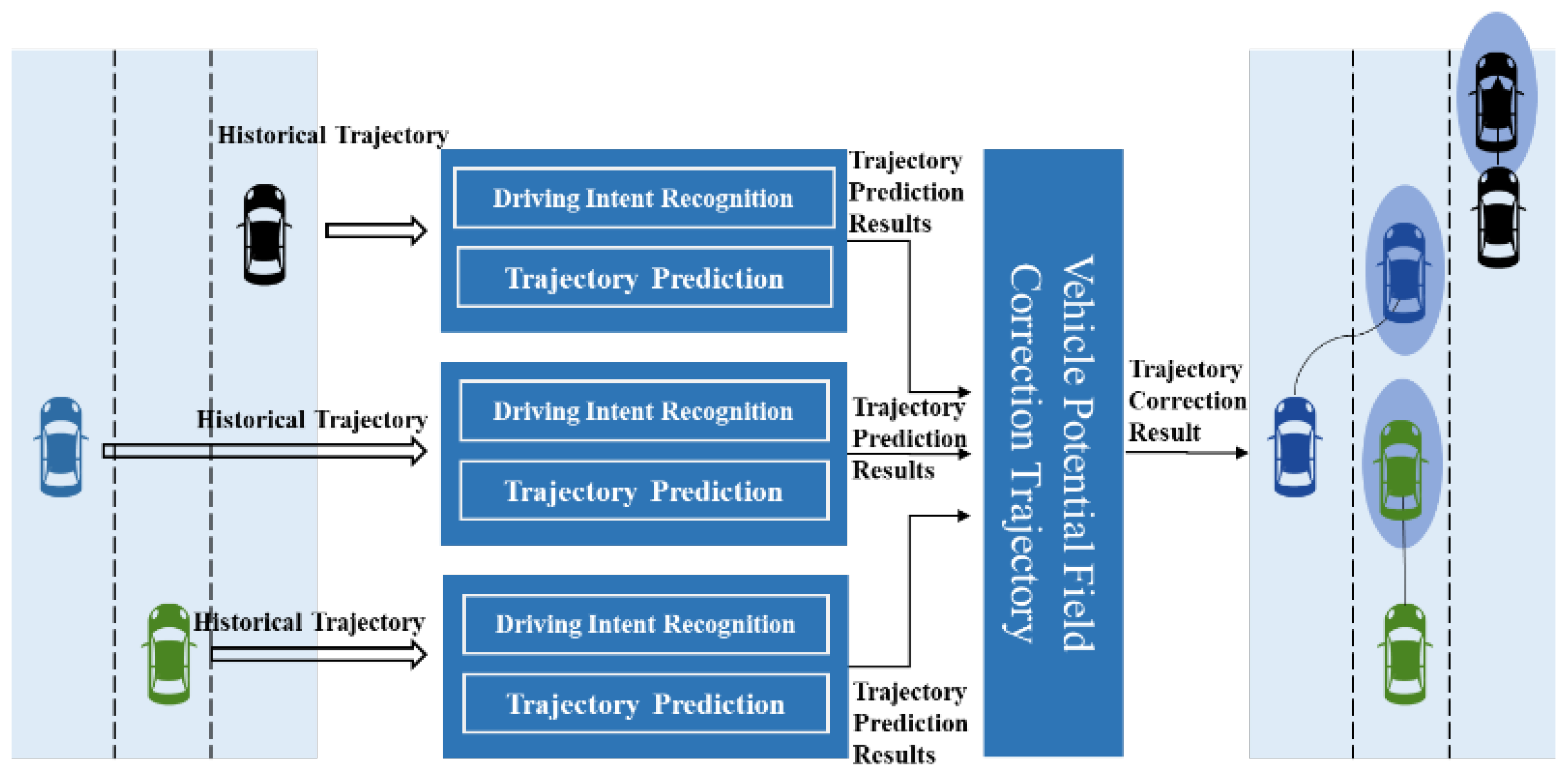
The accuracy of front vehicle trajectory prediction is largely influenced by the uncertainty of front vehicle driving intentions, dynamics, and inter-vehicle interactions and is challenged by limited data sources. Current approaches for vehicle trajectory prediction are divided into the following two approaches: parametric model-based methods and nonparametric data-driven methods [9,10,11]. There has been a large amount of work on parametric model-based trajectory prediction methods, including the use of physics-based or rule-based models [12,13,14,15,16]. The method has a strong environmental adaptation capability. However, with uncertainty in vehicle dynamics, it is impossible to build complex vehicle behavior models to derive sophisticated trajectory prediction algorithms, and in addition, the interaction effects between vehicles cannot be accurately described for each other. Therefore, model-based parametric approaches are not very reliable.
Data-driven nonparametric approaches based on historical data are trained with models to learn the nonlinear relationship between prediction and actual output. Yoon et al. [17] proposed a road-aware trajectory prediction method using HD maps and deep learning networks, using road structure constraints as the prior knowledge of the prediction network. The Uber research team [18] fused the predicted vehicle trajectories with lane-based paths Zou et al. [19] based on multiple sensors in an urban scenario and fused V2V data, and two transformer-based methods were built to predict the vehicle’s trajectory. Li et al. [20] proposed an end-edge-cloud architecture that deploys at the edge of the network machine learning-driven methods to predict the trajectory of the vehicle. The above trajectory prediction frameworks are highly dependent on data, such as road information and vehicle–vehicle communication, and may not work well in scenarios with limited data sources. Qu et al. [21] developed a data-driven predictive trajectory model based on long- and short-term memory, convolutional neural networks, and attention mechanisms. Wang et al. [22] used recurrent and convolutional neural networks to predict the vehicle trajectory in highway and urban scenarios and improved the prediction based on attention mechanisms. Choi et al. [23] proposed a vehicle trajectory prediction architecture based on a random forest (RF) algorithm and long short-term memory (LSTM). Shen et al. [24] predicted the coordinates of the target vehicle by visually identifying lane lines and vehicles and inputting the vehicle coordinate sequence into the LSTM algorithm. However, the above methods do not consider the driver’s driving intention and the interaction of the predicted object with the scene.
Interactions between vehicles significantly impact the accuracy of vehicle trajectory prediction. The problem becomes more complex when it involves interactions between objects and driving scene dynamics. The reason for this lies in how to model the interaction and scene dynamics. Lv et al. [25] model the trajectory correction mechanism based on an interactive network model. Zhao et al. [26] model the interactions and constraints between vehicles based on the novel Multi-Agent Tensor Fusion to predict the trajectory of vehicles. Yu et al. [27] proposed an LSTM model. The model predicts the trajectory of a vehicle by using an attention mechanism to manage the driving process of the target and adjacent vehicles and the importance of the target vehicle. Eunsan Jo et al. [28] proposed a hierarchical graph neural network for approximating the multiple maneuvers of a vehicle and considering the interactions between maneuvers by representing their relationships in a graph structure. Li et al. [29] predicted the probability of trajectories of multiple interacting entities based on dynamic Bayesian networks. Robicquet et al. [30] improved prediction models and multi-objective tracking tasks based on social sensitivity. Park et al. [31] proposed models that integrate multiple input signals, including environmental influences and interactions between multiple surrounding vehicles.
Multi-modal prediction based on driving intention classification is necessary because driving intention is uncertain and difficult to observe directly by sensors. The purpose of driving intention classification is to determine the future operating behavior of a vehicle [3], such as lane keeping or steering, acceleration, or deceleration. Cosimi et al. [32] estimated that the trajectory should remain within the defined level range to achieve similar results to the driving intention classification by the MPC control algorithm. Zyner et al. [33] classified the driving intention of a vehicle at a T-intersection as “east,” “west,” and “south” based on the destination of the vehicle. In [34], the driving intentions of vehicles were predicted in an unsignalized roundabout intersection scenario. Lee et al. [35] applied intention prediction to a highway driving scenario based on convolutional neural networks to infer the lane change intention of traffic participants. The drawback of the existing studies is that they can only provide high-level predictions of vehicle behavior but do not refine them to accurately describe operational intention [36]. For example, the lane change operation is subdivided into sharp and normal lane change, and the acceleration operation is subdivided into sharp and slow acceleration [37]. For example, Wang et al. [38] used acceleration and deceleration behavior, accelerated behavior, and operational stability as feature parameters to classify driver driving behavior using the Fuzzy C-Means (FCM) clustering method. Liu et al. [39] used speed, acceleration, and gas pedal opening as feature quantities of the FCM algorithm to classify driving style.

3. System Overview

The motion prediction of the front vehicle is affected by the problem of unclear driving intention and dynamics of the front vehicle. In addition, the future trajectory of the vehicle is influenced by other surrounding vehicles. In order to improve the estimation and prediction accuracy, the following ideas are proposed in this paper. Firstly, the FCM algorithm is used to extract the corresponding feature parameters by using the information related to the vehicle’s historical trajectory and realize the automatic recognition of driving intention through offline training; secondly, the LSTM algorithm is used to calculate the future trajectory results based on different driving intentions, and the predicted trajectories are fused according to the classification results of driving intentions, and the 1s rolling prediction is performed by the iterative method. Finally, the artificial potential field method is used to correct the predicted trajectory results based on the longitudinal and lateral safety distances, and the final trajectory prediction results are output. The structure diagram of the front vehicle trajectory prediction algorithm is shown in Figure 1.

3.1. Driving Intention Classification

Generally, drivers must turn on the turn signal in the corresponding direction before performing a lane change operation. However, statistics show [40] that turn signals are used while turning in only 64% of cases, but some drivers signal only after starting a lane change and fail to use their turn signals in 70% of cases when other vehicles are nearby. Therefore, it is not enough to use turn signals alone as an identification feature for driving intention, and other feature parameters need to be used to distinguish driving intention.
In order to solve the problem of the unclear driving intention of the preceding vehicle, the FCM algorithm is used to classify driving intentions. The FCM algorithm is used to solve the problem of the unclear driving intention of the front vehicle. The final output of the FCM algorithm is the magnitude of the degree to which each object belongs to each class, rather than providing only high-level predictions of vehicle behavior that do not accurately describe the problem of operating intentions.
Using the relative offset of the current prediction window lateral and longitudinal coordinates and the current vehicle speed as feature parameters, respectively, the vehicle driving intentions are classified, and the driving intentions are categorized as drastic lateral change, lateral slow change, lateral uniform change, drastic longitudinal change, slow longitudinal change, and longitudinal uniform change driving. The vehicle’s tendency to change in longitudinal and lateral directions is described in the form of probabilities to classify the vehicle’s driving intentions and improve the classification’s accuracy. Driving intentions are classified in terms of how drastically they change in the lateral and longitudinal directions so that if moving at a constant acceleration, driving intentions will classify this situation as a uniform change.
In order to classify driving intentions, Table 1 shows the selected characteristic parameters.
A portion of the real vehicle data C t , l = [ V t , l , X t , l , Y t , l ] is selected as the training set, Where C t , l is the data of the l th vehicle at time t, V t , l is the speed information of the l th vehicle at time t, and X t , l , Y t , l is the relative position offset of the l th vehicle in the lateral and longitudinal directions at time t. As an example of classifying the driving intention of vehicle 1 for the next 1 step, the historical 4-step and the current moment data are composed as a set of data [ C 4 , 1 , C 3 , 1 , C 2 , 1 , C 1 , 1 , C 0 , 1 ] . When classifying lateral driving intentions, A t , l is calculated by Equation (1) with the value of A t , l _ x in Equation (3). When classifying longitudinal driving intentions, A t , l is calculated by Equation (2) with the value of A t , l _ y in Equation (3). When classifying lateral driving intentions, Equation (5) outputs u t j _ x , which is the probability of belonging to class j of lateral driving intentions at time t. When classifying the longitudinal driving intentions, Equation (5) outputs the result as u t j _ y , which is the probability of belonging to class j longitudinal driving intentions at moment t. Ultimately, the FCM model outputs the result of the vehicle’s affiliation function [ u t 1 _ x , u t 2 _ x , u t 3 _ x ] in the lateral direction and the result of the affiliation function [ u t 1 _ y , u t 2 _ y , u t 3 _ y ] in the longitudinal direction.
The FCM algorithm is applied to determine the clustering center and affiliation matrix.
A t , l _ x = [ V t , l , max ( X t 4 , l , X t 3 , l , X t 2 , l , X t 1 , l , X t , l ) ,   min ( X t 4 , l , X t 3 , l , X t 2 , l , X t 1 , l , X t , l ) ]
A t , l _ y = [ V t , l , max ( Y t 4 , l , Y t 3 , l , Y t 2 , l , Y t 1 , l , Y t , l ) ,   min ( Y t 4 , l , Y t 3 , l , Y t 2 , l , Y t 1 , l , Y t , l ) ]
J = t = 1 N j = 1 3 u t j m A t , l c j
where J is the objective function, c j denotes the clustering center of class j, u t j denotes the affiliation degree of sample A t , l belonging to class j, N is the dataset size, and m is fuzzy partition matrix exponent for controlling the degree of fuzzy overlap, with m > 1.
After initializing the affiliation function, according to Equations (4) and (5), u t j and c j are continuously iterated and updated so that minimize Equation (3) under the condition that t = 1 3 u t j = 1 and finally reaches a stable state, and the values of u t j , c j in this state are the final affiliation matrix and clustering centers.
c j = t = 1 N u t j m A t , l t = 1 N u t j m ( j = 1 , 2 , 3 )
u t j = 1 k = 1 3 ( A t , l c j A t , l c k ) 2 m 1
For a single sample A t , l , the sum of the affiliation degree for each class is 1. The closer the affiliation degree u t j is to 1, the higher the degree of A t , l belonging to c j , and the affiliation function u t j , which takes the value in the interval (0,1), is used to characterize the degree of x i belonging to c j .
For the driving intention classification problem, the current and historical four-step sampling moment data are used as a group during the vehicle’s actual driving, and the group’s feature values are extracted. Moreover, the distance from the current moment data to each cluster center and the corresponding affiliation function are calculated using Equation (3) to characterize the probability that it belongs to that cluster center, and this probability is used as the weight coefficient of the trajectory prediction results based on different driving intentions. The accuracy of driving intention classification is improved by forming a combination of probabilities of different driving intentions.

3.2. Trajectory Prediction

The vehicle trajectory prediction problem is impacted by uncertainty in dynamical properties. Deep neural network architectures have been applied to many machine learning tasks and can generalize the nonlinear problems between real data and the environment. Among the existing deep neural network architectures, recurrent neural networks (RNNs) are widely used to analyze the structure of time series data, and RNNs have better results in targeting time series data. This paper uses a long short-memory (LSTM) model to predict the front car trajectory. LSTM is a variant in RNN, which has the same ability to learn long-term dependencies from the dataset and handle time series data as RNN. The LSTM algorithm can avoid the gradient disappearance/explosion problem of traditional RNN algorithms. In terms of structure, LSTM and RNN are dynamic structures containing repetitive blocks forming a chain. Within the repetition block, the difference between LSTM and traditional recurrent neural network is mainly its added gate structure, which is the forgetting gate, input gate, and output gate [41].
The relevant formula for LSTM is.
x t , l _ x = [ X t 4 , l , X t 3 , l , X t 2 , l , X t 1 , l , X t , l ]
x t , l _ y = [ Y t 4 , l , Y t 3 , l , Y t 2 , l , Y t 1 , l , Y t , l ]
f t , l = σ ( W f h t 1 , l + U f x t , l + b f )
i t , l = σ ( W i h t 1 + U i x t , l + b i )
C t , l = tanh ( W c h t 1 , l + U c x t , l + b c )
C t , l = f t , l C t 1 , l + i t , l C t , l
O t , l = σ ( W O h t 1 , l + U O x t , l + b O )
h t , l = O t , l tanh ( C t , l )
where f t , l denotes the forgetting gate, which controls the proportion of selectively forgotten information and i t , l denotes the input gate; when predicting the lateral trajectory, x t , l is calculated by Equation (6) and predicts the lateral trajectory with the value of x t , l _ x . When classifying longitudinal driving intentions, x t , l is calculated by Equation (7) and predicts the lateral trajectory with the value of x t , l _ y . C t , l denotes the state update, and the role of the input gate is to control the proportion of the state update C t , l added to the t-th step memory cell. O t , l denotes the output gate, which determines the proportion of output information. h t , l denotes the final output value and when classifying the lateral driving intention, the output of Equation (13) is h t , l _ x , which indicates the predicted result of the trajectory of car l in the lateral direction at the moment t. When classifying the longitudinal driving intention, Equation (13) outputs the result as h t , l _ y , which indicates the predicted result of the trajectory of car l in the longitudinal direction at the moment t and the final output of the LSTM is determined by both the output gate and the cell state. W f , U f , W i , U i , W c , U c , W O denotes the weight coefficient, b f , b i , b c , b O denotes the bias, and σ = 1 1 + e x is the activation function.
Based on the FCM, the driving intention of the front vehicle is classified, and the LSTM algorithm predicts the trajectory of the front car. First, the LSTM model is trained using data with different driving intentions, the three LSTM prediction models based on the drastic lateral change, the slow lateral change, and the lateral uniform change, and the three LSTM prediction models based on the drastic longitudinal change, the slow longitudinal change, and the longitudinal uniform change, were formed, respectively. Additionally, the LSTM algorithm takes the historical four-step length and current trajectory data as input and the future one-step trajectory as output to derive the LSTM prediction results under different driving intentions. When predicting the lateral trajectory, the three LSTM lateral prediction models with different lateral driving intentions yielded [ h t , l _ x 1 , h t , l _ x 2 , h t , l _ x 3 ] . The three LSTM longitudinal prediction models with different longitudinal driving intentions yielded [ h t , l _ y 1 , h t , l _ y 2 , h t , l _ y 3 ] when predicting the longitudinal trajectory. Then the vehicle data are input to the FCM algorithm, combined with the FCM algorithm to determine the probability of different driving intent, and the probability is used as the weight coefficient of the trajectory prediction results. Furthermore, finally, the multi-model prediction results are fused to derive the trajectory prediction results based on driving intention classification. Take the future trajectory prediction of vehicle 1 with 1 step length as an example, and input the historical four-step length and current data into FCM driving intention classification model and LSTM trajectory prediction model. The FCM model outputs the result of vehicle affiliation function [ u t 1 _ y , u t 2 _ y , u t 3 _ y ] in the longitudinal direction and [ u t 1 _ x , u t 2 _ x , u t 3 _ x ] in the lateral direction. The LSTM model outputs the future longitudinal coordinate [ h t , l _ y 1 , h t , l _ y 2 , h t , l _ y 3 ] and lateral coordinate [ h t , l _ x 1 , h t , l _ x 2 , h t , l _ x 3 ] under different driving intentions. The future one-step trajectory prediction result [ x t p 1 , y t p 1 ] for the final vehicle 1 is shown in Equations (14) and (15).
x t p 1 = u t 1 _ x × h t , l _ x 1 + u t 2 _ x × h t , l _ x 2 + u t 3 _ x × h t , l _ x 3
y t p 1 = u t 1 _ y × h t , l _ y 1 + u t 2 _ y × h t , l _ y 2 + u t 3 _ y × h t , l _ y 3
The structure of the algorithm for trajectory prediction for 1-step is shown in Figure 2.

3.3. Vehicle Interaction Correction

The predicted object is influenced by other traffic participants around it during its movement. However, the data-driven method does not consider the influence of other surrounding traffic participants in the prediction results. The purely data-driven method lead to prediction results that are inevitably detached from the essential characteristics of the predicted object and therefore needs to be corrected by environmental influences and the vehicle kinematic model of the predicted object itself to improve the algorithm’s environmental adaptability and accuracy. In this study, the artificial potential field (APF) method is used to calculate the repulsive field of the vehicle around the prediction object, and based on the vehicle dynamics model, the longitudinal and lateral safety distances are calculated to determine the influence range of the repulsive field, and finally, the trajectory prediction results are corrected.
The basic principle of the APF method is to assume the vehicle as a point that moves in a virtual force field, which is composed of the gravitational field of the target point to the vehicle and the repulsive field of the obstacle to the vehicle. Different from the traditional trajectory planning scenario, in this paper, APF is applied to trajectory prediction without using the gravitational field-related content, and the vehicle safety distance is used as one of the parameters in the repulsive field to achieve the correction of the prediction results, as shown in Equation (16).
R ( c ) = R r e p ( c )
c is the vehicle’s coordinate, R r e p ( c ) is the repulsive field, and R ( c ) is the sum of the repulsive fields.
The forces on the vehicle in the potential field are shown in Equation (17).
F ( c ) = R r e p ( c ) = F r e p ( c )
F ( c ) is the combined force on the vehicle, and F r e p ( c ) is the repulsive force that keeps the vehicle away from the obstacle point. The repulsive field is as in Equation (18).
R r e p = { 0 , i f ρ o b s ( c ) ρ 0 1 2 K r e p ( 1 ρ o b s ( c ) 1 ρ 0 ) 2 , i f ρ o b s ( c ) < ρ 0
where K r e p is the repulsive force gain constant, ρ o b s ( c ) = c c o b s is the obstacle coordinates. ρ 0 is the maximum influence distance. The repulsive force is calculated as (19).
F r e p = R r e p ( c ) = { 0 , i f ρ o b s ( c ) ρ 0 K r e p ( 1 ρ o b s ( c ) 1 ρ 0 ) ( 1 ρ 2 o b s ( c ) ) c c o b s c c o b s , i f ρ o b s ( c ) < ρ 0
In the scenario of multiple traffic participants, the repulsive field and repulsive force should be the sum of the repulsive field and the repulsive force of multiple traffic participants on the vehicle.
R ( c ) = R r e p ( c ) + i = 1 n R r e p ( c )
F ( c ) = F r e p ( c ) + i = 1 n F r e p ( c )
In this paper, the artificial potential field method is used to establish the surrounding vehicle potential field based on the vehicle safety distance, which is used to correct the predicted trajectory results and the erroneous results that lead to accidents of vehicles.
According to [42], Equations (18) and (19) are used for the calculation of longitudinal safety distance and lateral safety distance as follows:
d y = v 1 T r + 1 2 a max a c c T r 2 + ( v 1 + T r a max a c c ) 2 2 a min b r k v 2 2 2 a max b r k
d x = v 1 + v 1 + T r a max a c c 2 T r + ( v 1 + T r a max a c c ) 2 2 a min b r k v 2 + | v 2 | + T r a max a c c 2 T r + ( | v 2 | + T r a max a c c ) 2 2 a min b r k
T r is the reaction time, a max a c c is the maximum longitudinal acceleration, a min b r k is the minimum longitudinal braking required to avoid a collision, and a max b r k is the maximum longitudinal braking acceleration.
The potential field combines longitudinal and lateral safety distances to limit the minimum distance of the predicted vehicle from surrounding vehicles under the current driving intention and establishes a repulsive field of surrounding vehicles to predict the vehicle trajectory. The final prediction position is shifted to the edge of the repulsive field both horizontally and vertically to reduce the problem of ignoring the actual scenario constraints caused by the purely data-driven approach to predict trajectories and to improve the interaction with the surrounding environment in the trajectory prediction process.

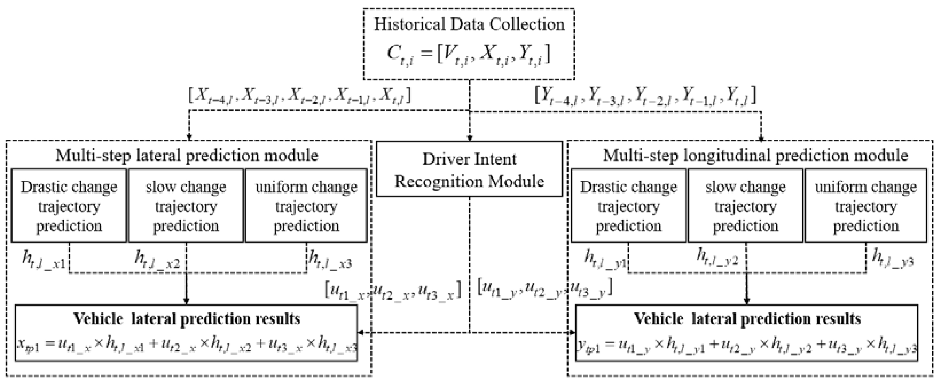
3.4. Multi-Step Prediction

Multi-step prediction methods are mainly divided into direct and iterative methods. The iterative method uses the result of the previous prediction step as the input for the next prediction step until rolling the prediction up to the expected step. The direct method is to predict directly up to the kth step, but the trained model has to match the predicted step size, and models with different prediction steps cannot be substituted for each other [43]. Moreover, the direct method prediction model requires much more training data than the iterative method [44,45].
However, the iterative method is affected by the problem that the prediction error accumulates with the prediction step. To solve this problem, in this paper, driving intention is identified at each prediction step, and the APF algorithm is used to determine and correct the results for collision risk. The k-step prediction indicates that the data at the current moment is used to predict the next k sampling moments. For example, the five-step prediction indicates that the current moment data is used to predict the trajectory for the next five sampling moments. Taking the prediction of the future two-step trajectory as an example, firstly, the FCM algorithm is used to classify the driving intention. The input data are the historical three-step long and current moment trajectory information, the predicted future one-step trajectory information, and the driving intention affiliation function of this data set is output. Then, the LSTM algorithm is used to predict the future two-step trajectory and combined with the affiliation function calculated by FCM, and the trajectory prediction result based on driving intention is obtained. Finally, the APF algorithm is used to determine whether there is a collision risk at the predicted points and to correct the predicted points with a safety risk, resulting in the final trajectory prediction results.

4. Experimental Results and Analysis

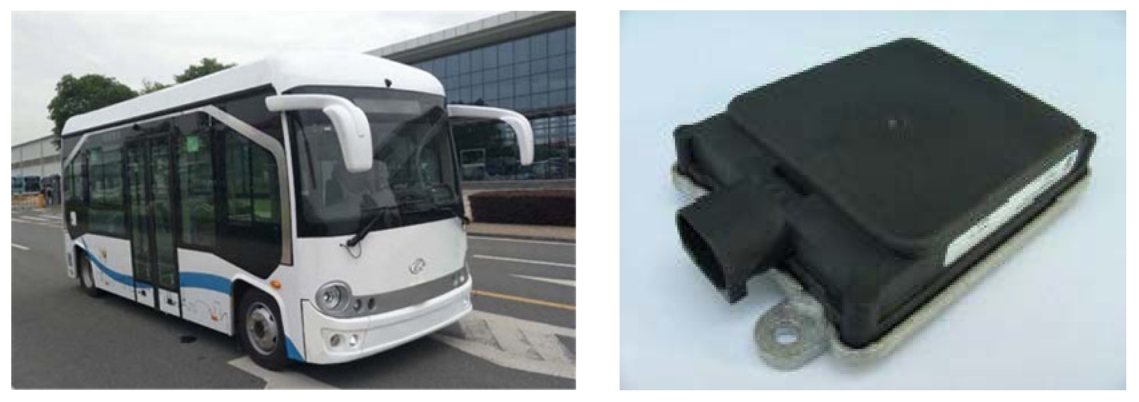
4.1. Research Subjects

The research subject of this paper is a purely electric bus with the specific configuration parameters shown in Table 2. The bus and the millimeter wave radar are shown in Figure 3.
The data for this study were obtained from the millimeter wave radar mounted on the vehicle and mounted at the vehicle’s front windshield. The collected vehicle data C t , l = [ V t , l , X t , l , Y t , l ] , where C t , l is the data of the ith vehicle, V t , l is the speed information of the previous vehicle, and X t , l , Y t , l is the relative position information of the vehicle in the horizontal and vertical directions. The data cover a wide range of operating conditions and are collected at a frequency of 10 Hz. The collected data are divided into a training set, a validation set, and a test set for the driving intention classification algorithm and the prediction algorithm.

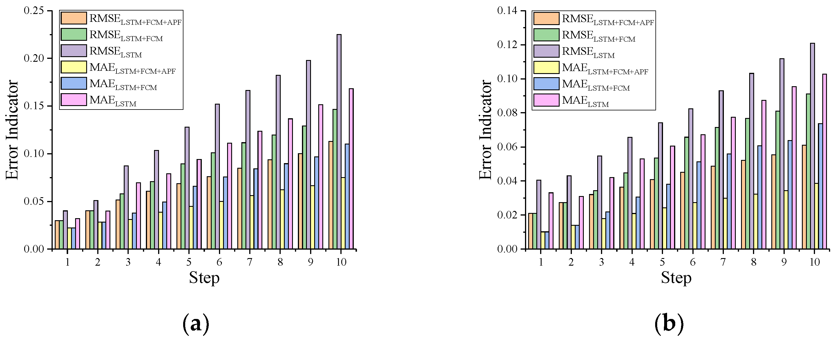
4.2. Evaluation Indicators

In this paper, root mean square error (RMSE) and mean absolute error (MAE) are indicators to evaluate the accuracy of trajectory prediction. Among them, the root mean square error measures the deviation between the predicted value and the true value and is more sensitive to the outliers in the data, and the mean absolute error represents the average of the absolute error between the predicted value and the observed value. The calculation formula is shown in Equations (24) and (25).
R M S E ( X , h ) = 1 m i = 1 m ( h ( x i ) y i ) 2
M A E ( X , h ) = 1 m i = 1 m | h ( x i ) y i |
where m is the sample size, h ( x i ) is the predicted value, and y i is the true value.

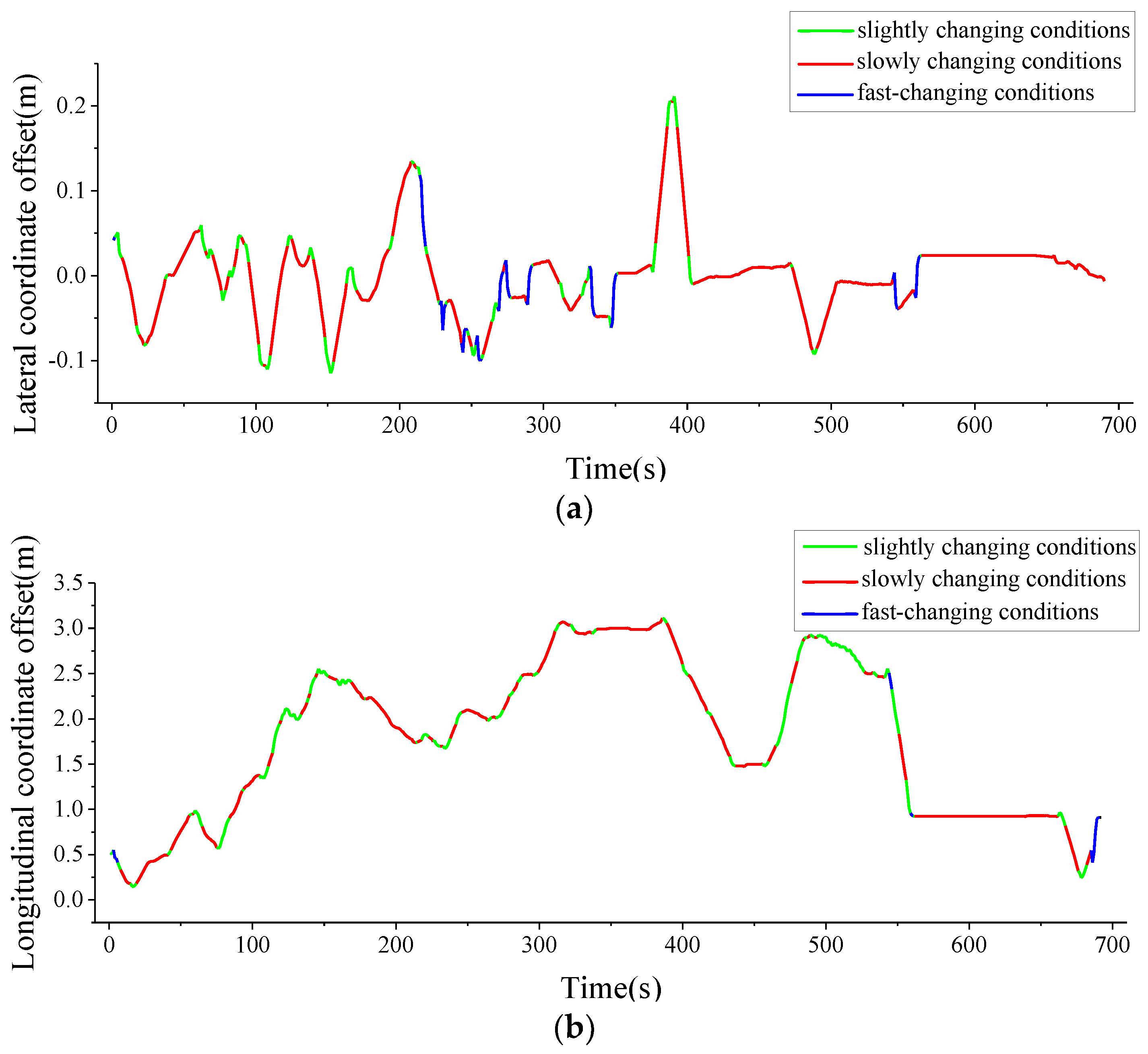
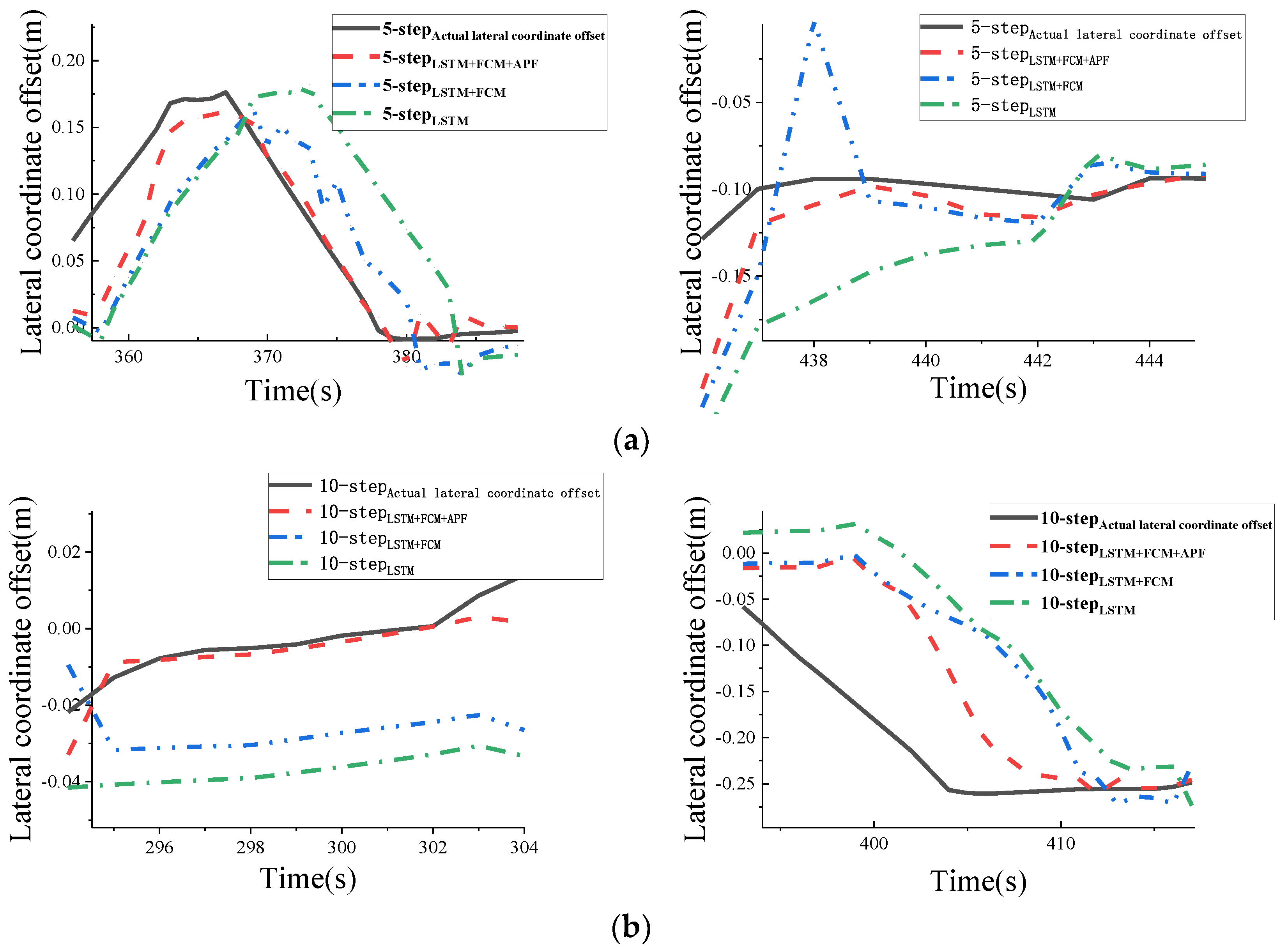
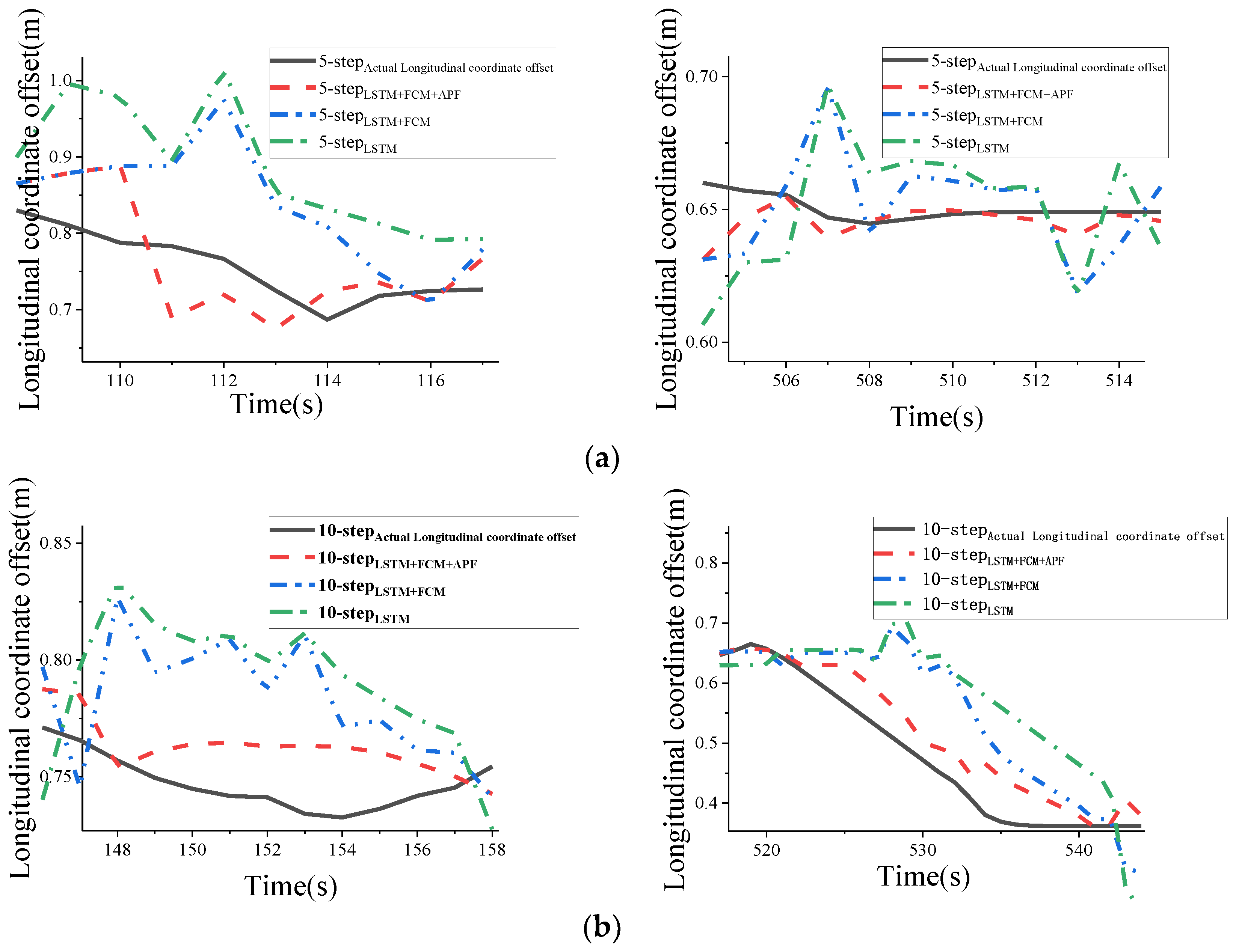
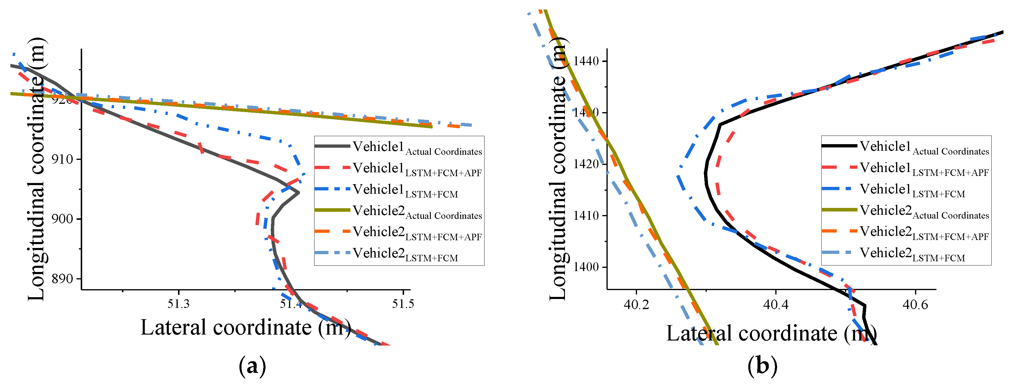
4.3. Analysis of Experimental Results

Figure 4 shows the driving intention classification results for one set of vehicle data, with different colors representing different driving intentions in the lateral and longitudinal directions. In addition, the driving intention classification aims to distinguish the trend and degree of change in the lateral and longitudinal coordinates rather than the magnitude of the slope of change. In the case of the longitudinal driving intention classification, for example, the longitudinal uniform change includes both uniform motion and uniform acceleration in the longitudinal direction.
The iterative method predicts the future lateral and longitudinal coordinate offsets of multiple vehicles ahead in multiple steps. Only the lateral coordinate prediction results of vehicle 1 are shown in Figure 5 and Figure 6. Figure 5 is the comparison curves of the lateral coordinate prediction results for the 5-step and 10-step prediction, respectively. As can be seen from the figures, firstly, the prediction error of each algorithm increases with the increase of the prediction step length, and there is a certain lag in the prediction results. However, APF can correct the prediction results that lead to collision risk. Second, in the case of changes in the lateral coordinate, the algorithms that do not use driving intention classification have more aggressive prediction results, and smaller changes can have a larger impact on the prediction impact. The prediction curve of the algorithm proposed in this paper is closer to the true lateral coordinates of the vehicle in front, and the prediction error is significantly reduced.
Figure 6 shows the plot of the prediction curves of the 5-step and the 10-step of the longitudinal coordinate of vehicle 1. As can be seen from the figure, firstly, as the prediction step increases, the prediction results of each algorithm show an increase in error and a lag in the prediction results, as in the case of the prediction in the longitudinal coordinates. Second, in the case of longitudinal coordinate changes, the other two methods have more aggressive prediction results than the algorithm used in this paper. Smaller changes can have a larger impact on the prediction impact, which leads to an increase in the prediction error. The prediction curve of the algorithm proposed in this paper is closer to the real longitudinal coordinates of the vehicle, and the prediction error is significantly reduced.
Figure 7 shows the trajectory prediction curves for the 5-step and 10-step of vehicle 1 and vehicle 2. From the Figure, it can be seen that in the trajectory prediction during the turn, the two algorithms predict the results with different degrees of deviation. There is a lag in the prediction results. However, the APF algorithm can correct the results with the risk of collision, thus reducing the prediction error and showing the applicability of this algorithm in the interaction between vehicles.
Table 3 and Table 4 show the error distribution in the 5-step prediction and 10-step prediction with different prediction methods as an example of the prediction results of vehicle 1. As shown in Table 3 and Table 4 for the comparison of prediction errors in the lateral coordinates, it can be seen from the table that the prediction errors of all three methods increase with increasing step length in the prediction results of the 5-step prediction and the 10-step prediction. In addition, the FCM-based LSTM algorithm has smaller error means and error variances than the prediction results of the LSTM with deviations in the lateral coordinates. After adding APF correction to the FCM-based LSTM algorithm, the mean and variance of the errors were further reduced, and the prediction results proved to be more accurate.
Table 5 and Table 6 also show the error distribution in the 5-step prediction and 10-step prediction with different prediction methods, as shown in Table 5 and Table 6 for the comparison of the prediction error in the longitudinal coordinate, which shows that the prediction error of all three methods increases with the increase in the step length. The FCM-based LSTM algorithm has a smaller mean error and error variance than the LSTM prediction results with a deviation of longitudinal coordinates. Adding APF correction to the FCM-based LSTM algorithm further reduces the mean and variance of the errors and proves that the prediction results are more accurate.
Comparing the results of the trajectory prediction algorithm for multiple vehicles ahead, Figure 8 shows the metric results of RMSE and MAE at different steps using different prediction methods using vehicle 1 as an example. Before the third step length, the RMSE and MAE metrics results are similar because the prediction error is small, resulting in fewer cases of prediction results falling into the range of other vehicle potential fields. As the prediction step length increases, the prediction error increases, and the APF corrects the prediction results when it appears that the prediction results fall into the range of other vehicle potential fields, and the corrected results continue to affect the subsequent prediction results. The RMSE and MAE values of the algorithm in this paper, both lower than the other two algorithms, prove the effectiveness of this algorithm.
The prediction results of this algorithm for multi-vehicle trajectory prediction compared with the actual trajectory are shown in Figure 9. The trajectory prediction for the next 1s was carried out for three vehicles, in which the prediction error of vehicle 1 in the tenth step of the longitudinal distance was less than 0.17 m in 95% of the prediction results, and the maximum distance prediction error was 0.29 m among all the prediction results. The prediction error of vehicle 2 at the tenth step of longitudinal distance is less than 0.13 m in 95% of the prediction results, and the maximum distance prediction error is 0.30 m in all the prediction results; 95% of the prediction error of vehicle 2 at the lateral distance is less than 0.11 m, and the maximum distance prediction error is 0.14 m in all the prediction results. The prediction error of the longitudinal distance of vehicle 3 at the tenth step is less than 0.16 m in 95% of the prediction results, and the maximum distance prediction error is 0.33 m in all the prediction results; 95% of the prediction error of the lateral distance of vehicle 3 is less than 0.03 m in all the prediction results, and the maximum distance prediction error is 0.10 m in all the prediction results.

5. Conclusions

This paper aims to improve the prediction accuracy of forwarding vehicle behavior, reduce the influence of uncertainties such as driving intention, dynamics characteristics, and vehicle interaction effects on the prediction results, and construct a forward vehicle behavior prediction algorithm based on driving intention classification and vehicle interaction modeling correction. In order to accurately predict the trajectory of the front vehicle, this paper classifies the driving intention based on the FCM algorithm, then uses the LSTM algorithm to predict the trajectory of the front vehicle and corrects the trajectory prediction results by the APF algorithm and finally combines to calculate the future trajectory.
First, considering the influence on the future trajectory of the vehicle ahead under different driving intentions, the FCM algorithm outputs the probability of the current data belonging to each category by taking the previous vehicle speed and trajectory information as input to improve the resolution and accuracy of the classification.
Second, the historical and current trajectory data under different driving intention are used to train the LSTM model to predict trajectories under different driving intentions, and the affiliation function of FCM output, as the weight of each model, is used for the weighted fusion of prediction results with different driving intents with variable gain. The rolling prediction of the trajectory of multiple targets ahead for 1s is performed by an iterative method.
The APF method is used to establish repulsive vehicle fields based on longitudinal and lateral safety distances to correct the trajectory results that have the risk of collision or do not match the actual situation driving operation. In this way, the interaction with the surrounding environment is improved in the trajectory prediction process.
The algorithm is validated using real vehicle data. In the test results of different vehicles and scenes, 95% of the longitudinal distance prediction results have an error less than 0.17 m, and the maximum distance prediction error is 0.33 m; 95% of the lateral distance prediction results have an error less than 0.11 m, and the maximum distance prediction error is 0.15 m, which proves the accuracy of the algorithm and the good scene adaptation ability.

Author Contributions

Conceptualization, W.M.; software, W.M.; validation, W.M.; resources, W.M., Y.Z. and Z.W.; data curation, W.M.; writing—original draft preparation, W.M.; writing—review and editing, W.M., Y.Z. and Z.W.; visualization, W.M.; supervision, Y.Z. and Z.W. All authors have read and agreed to the published version of the manuscript.

Funding

This research received no external funding.

Data Availability Statement

Not applicable.

Conflicts of Interest

The authors declare no conflict of interest.

References

  1. Bello, L.L.; Mariani, R.; Mubeen, S.; Saponara, S. Recent advances and trends in on-board embedded and networked automotive systems. IEEE Trans. Ind. Inf. 2019, 15, 1038–1051. [Google Scholar] [CrossRef]
  2. Woo, H.; Ji, Y.; Tamura, Y.; Kuroda, Y.; Sugano, T.; Yamamoto, Y.; Yamashita, A.; Asama, H. Lane-change detection based on individual driving style. Adv. Robot. 2019, 33, 1087–1098. [Google Scholar] [CrossRef]
  3. Lefèvre, S.; Vasquez, D.; Laugier, C. A survey on motion prediction and risk assessment for intelligent vehicles. Robomech J. 2014, 1, 1–14. [Google Scholar] [CrossRef] [Green Version]
  4. Wasala, A.; Byrne, D.; Miesbauer, P.; O’Hanlon, J.; Heraty, P.; Barry, P. Trajectory based lateral control: A reinforcement learning case study. Eng. Appl. Artif. Intell. 2020, 94, 103799. [Google Scholar] [CrossRef]
  5. Dini, P.; Saponara, S. Processor-in-the-loop validation of a gradient descent-based model predictive control for assisted driving and obstacles avoidance applications. IEEE Access 2022, 10, 67958–67975. [Google Scholar] [CrossRef]
  6. Sharma, O.; Sahoo, N.C.; Puhan, N.B. Recent advances in motion and behavior planning techniques for software architecture of autonomous vehicles: A state-of-the-art survey. Eng. Appl. Artif. Intell. 2021, 101, 104211. [Google Scholar] [CrossRef]
  7. Saponara, S.; Greco, M.S.; Gini, F. Radar-on-chip/in-package in autonomous driving vehicles and intelligent transport systems: Opportunities and challenges. IEEE Signal Process. Mag. 2019, 36, 71–84. [Google Scholar] [CrossRef]
  8. Deo, N.; Trivedi, M.M. Convolutional social pooling for vehicle trajectory prediction. In Proceedings of the IEEE Conference on Computer Vision and Pattern Recognition Workshops, Salt Lake City, UT, USA, 18–22 June 2018; pp. 1468–1476. [Google Scholar]
  9. Houenou, A.; Bonnifait, P.; Cherfaoui, V.; Yao, W. Vehicle trajectory prediction based on motion model and maneuver recognition. In Proceedings of the 2013 IEEE/RSJ International Conference on Intelligent Robots and Systems, Tokyo, Japan, 3–7 November 2013; IEEE: Manhattan, NY, USA, 2013; pp. 4363–4369. [Google Scholar]
  10. Dai, S.; Li, L.; Li, Z. Modeling vehicle interactions via modified LSTM models for trajectory prediction. IEEE Access 2019, 7, 38287–38296. [Google Scholar] [CrossRef]
  11. Lin, L.; Li, W.; Bi, H.; Qin, L. Vehicle trajectory prediction using LSTMs with spatial-temporal attention mechanisms. IEEE Intel. Transp. Syst. Mag. 2021, 14, 197–208. [Google Scholar] [CrossRef]
  12. Rummelhard, L.; Nègre, A.; Perrollaz, M.; Laugier, C. Probabilistic Grid-Based Collision Risk Prediction for Driving Application; Experimental Robotics; Springer: Cham, Switzerland, 2016; pp. 821–834. [Google Scholar]
  13. Xie, G.; Gao, H.; Qian, L.; Huang, B.; Li, K.; Wang, J. Vehicle trajectory prediction by integrating physics-and maneuver-based approaches using interactive multiple models. IEEE Trans. Ind. Electron. 2017, 65, 5999–6008. [Google Scholar] [CrossRef]
  14. Xiao, W.; Zhang, L.; Meng, D. Vehicle trajectory prediction based on motion model and maneuver model fusion with interactive multiple models. SAE Int. J. Adv. Curr. Pract. Mobil. 2020, 2, 3060–3071. [Google Scholar]
  15. Baek, M.; Jeong, D.; Choi, D.; Lee, S. Vehicle trajectory prediction and collision warning via fusion of multisensors and wireless vehicular communications. Sensors 2020, 20, 288. [Google Scholar] [CrossRef] [PubMed] [Green Version]
  16. Liu, W.; He, H.; Sun, F. Vehicle state estimation based on minimum model error criterion combining with extended Kalman filter. J. Frankl. Inst. 2016, 353, 834–856. [Google Scholar] [CrossRef]
  17. Yoon, Y.; Kim, T.; Lee, H.; Park, J. Road-aware trajectory prediction for autonomous driving on highways. Sensors 2020, 20, 4703. [Google Scholar] [CrossRef] [PubMed]
  18. Yalamanchi, S.; Huang, T.K.; Haynes, G.C.; Djuric, N. Long-term prediction of vehicle behavior using short-term uncertainty-aware trajectories and high-definition maps. In Proceedings of the 2020 IEEE 23rd International Conference on Intelligent Transportation Systems (ITSC), Rhodes, Greece, 20–23 September 2020; IEEE: Manhattan, NY, USA, 2020; pp. 1–6. [Google Scholar]
  19. Zou, B.; Li, W.; Hou, X.; Tang, L.; Yuan, Q. A framework for trajectory prediction of preceding target vehicles in urban scenario using multi-sensor fusion. Sensors 2022, 22, 4808. [Google Scholar] [CrossRef] [PubMed]
  20. Li, H.; Liu, F.; Zhao, Z.; Karimzadeh, M. Effective safety message dissemination with vehicle trajectory predictions in V2X networks. Sensors 2022, 22, 2686. [Google Scholar] [CrossRef] [PubMed]
  21. Qu, D.; Wang, S.; Liu, H.; Meng, Y. A car-following model based on trajectory data for connected and automated vehicles to predict trajectory of human-driven vehicles. Sustainability 2022, 14, 7045. [Google Scholar] [CrossRef]
  22. Wang, J.; Wang, P.; Zhang, C.; Su, K.; Li, J. F-net: Fusion neural network for vehicle trajectory prediction in autonomous driving. In Proceedings of the ICASSP 2021—2021 IEEE International Conference on Acoustics, Speech and Signal Processing (ICASSP), Toronto/Ontario, Canada, 6–11 June 2021; IEEE: Manhattan, NY, USA, 2021; pp. 4095–4099. [Google Scholar]
  23. Choi, D.; Yim, J.; Baek, M.; Lee, S. Machine learning-based vehicle trajectory prediction using v2v communications and on-board sensors. Electronics 2021, 10, 420. [Google Scholar] [CrossRef]
  24. Shen, C.H.; Hsu, T.J. Research on vehicle trajectory prediction and warning based on mixed neural networks. Appl. Sci. 2020, 11, 7. [Google Scholar] [CrossRef]
  25. Lv, P.; Liu, H.; Xu, J.; Li, T. Trajectory prediction with correction mechanism for connected and autonomous vehicles. Electronics 2022, 11, 2149. [Google Scholar] [CrossRef]
  26. Zhao, T.; Xu, Y.; Monfort, M.; Choi, W.; Baker, C.; Zhao, Y.; Wang, Y.; Wu, Y.N. Multi-agent tensor fusion for contextual trajectory prediction. In Proceedings of the IEEE/CVF Conference on Computer Vision and Pattern Recognition, Long Beach, CA, USA, 15–20 June 2019; pp. 12126–12134. [Google Scholar]
  27. Yu, D.; Lee, H.; Kim, T.; Hwang, S.H. Vehicle trajectory prediction with lane stream attention-based LSTMs and road geometry linearization. Sensors 2021, 21, 8152. [Google Scholar] [CrossRef] [PubMed]
  28. Jo, E.; Sunwoo, M.; Lee, M. Vehicle trajectory prediction using hierarchical graph neural network for considering interaction among multimodal maneuvers. Sensors 2021, 21, 5354. [Google Scholar] [CrossRef] [PubMed]
  29. Li, J.; Ma, H.; Zhan, W.; Tomizuka, M. Coordination and trajectory prediction for vehicle interactions via Bayesian generative modeling. In Proceedings of the 2019 IEEE Intelligent Vehicles Symposium (IV), Paris, France, 9–12 June 2019; IEEE: Manhattan, NY, USA, 2019; pp. 2496–2503. [Google Scholar]
  30. Robicquet, A.; Sadeghian, A.; Alahi, A.; Savarese, S. Learning social etiquette: Human trajectory understanding in crowded scenes. In Proceedings of the European Conference on Computer Vision, Odessa, Ukraine, 6 July 2019; Springer: Cham, Switzerland, 2016; pp. 549–565. [Google Scholar]
  31. Park, S.H.; Lee, G.; Seo, J.; Bhat, M.; Kang, M.; Francis, J.; Jadhav, A.; Liang, P.P.; Morency, L.-P. Diverse and admissible trajectory forecasting through multimodal context understanding. In Proceedings of the European Conference on Computer Vision, Glasgow, UK, 23–28 August 2020; Springer: Cham, Switzerland, 2020; pp. 282–298. [Google Scholar]
  32. Cosimi, F.; Dini, P.; Giannetti, S.; Petrelli, M.; Saponara, S. Analysis and design of a non-linear MPC algorithm for vehicle trajectory tracking and obstacle avoidance. In Applications in Electronics Pervading Industry, Environment and Society; Saponara, S., de Gloria, A., Eds.; ApplePies 2020; Lecture Notes in Electrical Engineering; Springer: Cham, Switzerland, 2020; Volume 738. [Google Scholar] [CrossRef]
  33. Zyner, A.; Worrall, S.; Ward, J.; Nebot, E. Long short term memory for driver intent prediction. In Proceedings of the 2017 IEEE Intelligent Vehicles Symposium (IV), Los Angeles, CA, USA, 11–14 June 2017; IEEE: Manhattan, NY, USA, 2017; pp. 1484–1489. [Google Scholar]
  34. Zyner, A.; Worrall, S.; Nebot, E. A recurrent neural network solution for predicting driver intention at unsignalized intersections. IEEE Robot. Automat. Lett. 2018, 3, 1759–1764. [Google Scholar] [CrossRef]
  35. Lee, D.; Kwon, Y.P.; McMains, S.; Hedrick, J.K. Convolution neural network-based lane change intention prediction of surrounding vehicles for ACC. In Proceedings of the 2017 IEEE 20th International Conference on Intelligent Transportation Systems (ITSC), Yokohama, Japan, 16–19 October 2017; IEEE: Manhattan, NY, USA, 2017; pp. 1–6. [Google Scholar]
  36. Liu, L.; Xu, G.; Song, Z. Driver lane changing behavior analysis based on parallel Bayesian networks. In Proceedings of the 2010 Sixth International Conference on Natural Computation, Yantai, China, 10–12 August 2010; IEEE: Manhattan, NY, USA, 2010; Volume 3, pp. 1232–1237. [Google Scholar]
  37. Mozaffari, S.; Al-Jarrah, O.Y.; Dianati, M.; Jennings, P.; Mouzakitis, A. Deep learning-based vehicle behavior prediction for autonomous driving applications: A review. IEEE Trans. Intell. Transp. Syst. 2020, 23, 33–47. [Google Scholar] [CrossRef]
  38. Wang, X.; Wang, H. Driving behavior clustering for hazardous material transportation based on genetic fuzzy C-means algorithm. IEEE Access 2020, 8, 11289–11296. [Google Scholar] [CrossRef]
  39. Liu, Y.; Wang, J.; Zhao, P.; Qin, D.; Chen, Z. Research on classification and recognition of driving styles based on feature engineering. IEEE Access 2019, 7, 89245–89255. [Google Scholar] [CrossRef]
  40. Olsen, E.C.B. Modeling Slow Lead Vehicle Lane Changing. Ph.D. Thesis, Virginia Polytechnic Institute and State University, Blacksburg, VA, USA, 2003. [Google Scholar]
  41. Graves, A. Long Short-Term Memory. Neural Comput. 1997, 9, 1735–1780. [Google Scholar]
  42. Corso, A.; Du, P.; Driggs-Campbell, K.; Kochenderfer, M.J. Adaptive stress testing with reward augmentation for autonomous vehicle validation. In Proceedings of the 2019 IEEE Intelligent Transportation Systems Conference (ITSC), Auckland, New Zealand, 27–30 October 2019; pp. 163–168. [Google Scholar] [CrossRef]
  43. Girard, A.; Rasmussen, C.E.; Quinonero-Candela, J.; Murray-Smith, R.; Winther, O.; Larsen, J. Multiple-step ahead prediction for non linear dynamic systems—A gaussian process treatment with propagation of the uncertainty. Adv. Neural Inf. Process. Syst. 2002, 15, 529–536. [Google Scholar]
  44. Hachino, T.; Kadirkamanathan, V. Time series forecasting using multiple gaussian process prior model. In Proceedings of the 2007 IEEE Symposium on Computational Intelligence and Data Mining, Honolulu, HI, USA, 1 March–5 April 2007; IEEE: Manhattan, NY, USA, 2007; pp. 604–609. [Google Scholar]
  45. Yan, W.; Qiu, H.; Xue, Y. Gaussian process for long-term time-series forecasting. In Proceedings of the 2009 International Joint Conference on Neural Networks, Atlanta, GA, USA, 14–19 June 2009; IEEE: Manhattan, NY, USA, 2009; pp. 3420–3427. [Google Scholar]
Figure 1. The architecture of the vehicle motion prediction algorithm.
Electronics 11 03857 g001
Figure 2. The structure of the algorithm for trajectory prediction for 1-step.
Electronics 11 03857 g002
Figure 3. The bus and the millimeter-wave radar.
Electronics 11 03857 g003
Figure 4. Driving Intention Classification Results: (a) Lateral Driving Intention Classification Results; (b) Longitudinal Driving Intention Classification Results.
Electronics 11 03857 g004
Figure 5. Lateral coordinate prediction results: (a) lateral coordinate 5−step prediction results and (b) lateral coordinate 10−step prediction results.
Electronics 11 03857 g005
Figure 6. Longitudinal coordinate prediction results: (a) longitudinal coordinate future 5−step prediction results and (b) longitudinal coordinate future 10−step prediction results.
Electronics 11 03857 g006
Figure 7. Multi-vehicle trajectory prediction results: (a) future 5−step prediction results and (b) future 10−step prediction results.
Electronics 11 03857 g007
Figure 8. Vehicle multi-step coordinate prediction results: (a) multi-step prediction results for the lateral coordinate of vehicle 1 and (b) multi-step prediction results for the longitudinal coordinate of vehicle 1.
Electronics 11 03857 g008
Figure 9. Multi-step prediction of multi-vehicle trajectory results.
Electronics 11 03857 g009
Table 1. Characteristic parameter table.
No.Characteristic Parameters
1Vehicle speed (m/s)
2Lateral coordinate relative maximum offset (m)
3Lateral coordinate relative minimum offset (m)
4Longitudinal coordinate relative maximum offset (m)
5Longitudinal coordinate relative minimum offset (m)
Table 2. Electric bus parameter configuration table.
Parameter
Length (mm)6605
Width (mm)2320
Height (mm)2870
Maximum Speed (km/h)69
Table 3. The 5−step of the lateral coordinate prediction results.
Prediction AlgorithmsMean ValueVariance
LSTM + FCM + APF0.0223670.000753
LSTM + FCM0.034780.001322
LSTM0.0545490.002092
Table 4. The 10−step of the lateral coordinate prediction results.
Prediction AlgorithmsMean ValueVariance
LSTM + FCM + APF0.0350860.001718
LSTM + FCM0.0546990.00277
LSTM0.0848630.008036
Table 5. The 5−step of the longitudinal coordinate prediction results.
Prediction AlgorithmsMean ValueVariance
LSTM + FCM + APF0.0061135.02 × 10−5
LSTM + FCM0.0089886.8 × 10−5
LSTM0.0128330.000141
Table 6. The 10−step of the longitudinal coordinate prediction results.
Prediction AlgorithmsMean ValueVariance
LSTM + FCM + APF0.0297710.001118
LSTM + FCM0.0432560.00147
LSTM0.0677880.003272
Publisher’s Note: MDPI stays neutral with regard to jurisdictional claims in published maps and institutional affiliations.

