

A 177 ppm RMS Error-Integrated Interface for Time-Based Impedance Spectroscopy of Sensors

 ,
,  ,
,  ,
,  and
and 
Abstract
:1. Introduction
2. System Architecture
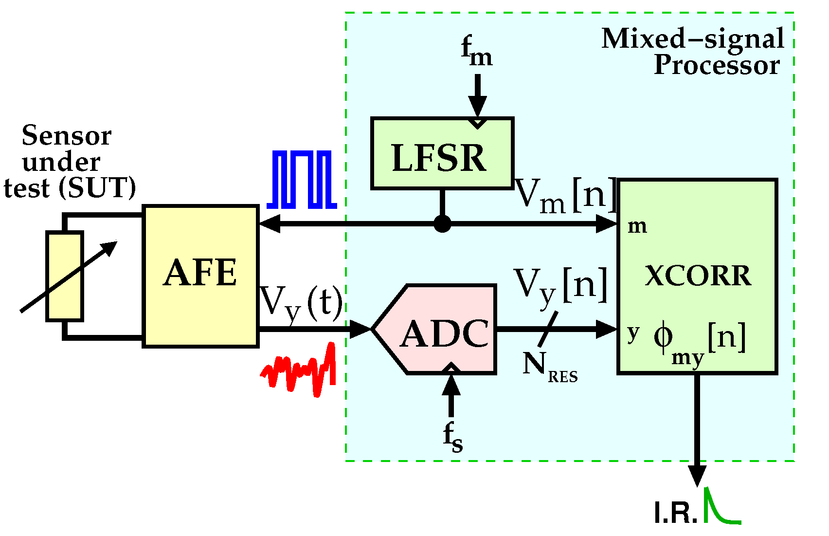
2.1. Overview and Conventional Approach
- The quantization noise no longer affects the cross-correlation operation; thus, only the electronic noise contributes to the error in the measured IR;
- Since the ADC must convert only the last sample of the entire cross-correlation process, the sampling rate requirement of the ADC is greatly relaxed;
- RAM usage is totally avoided, simplifying the digital design of the system.
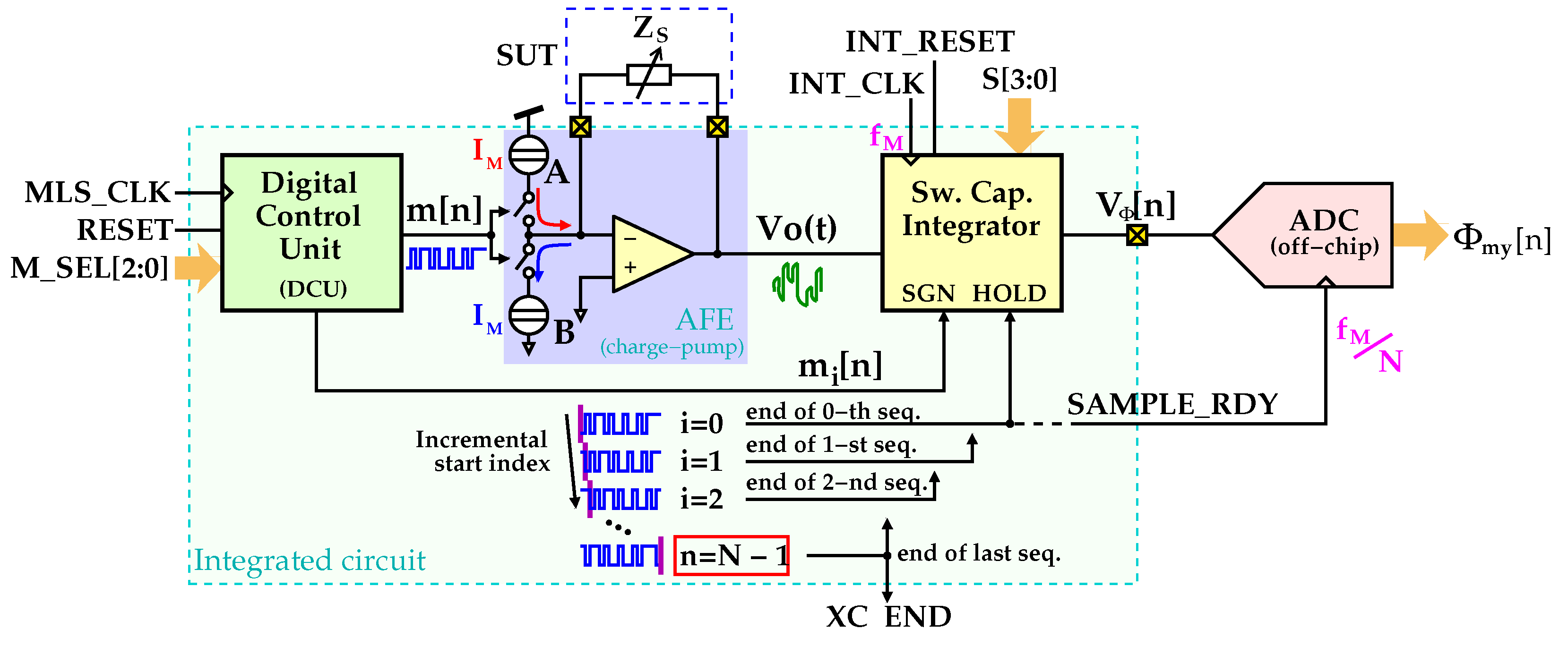
2.2. Proposed Analog Solution
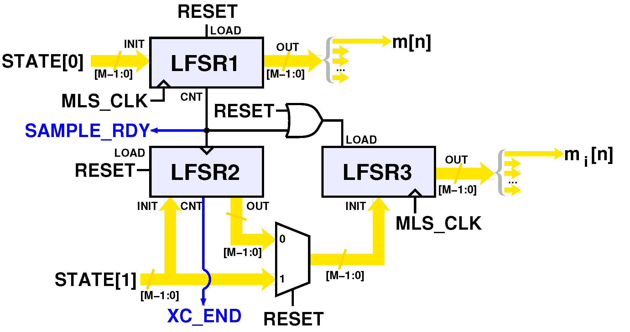
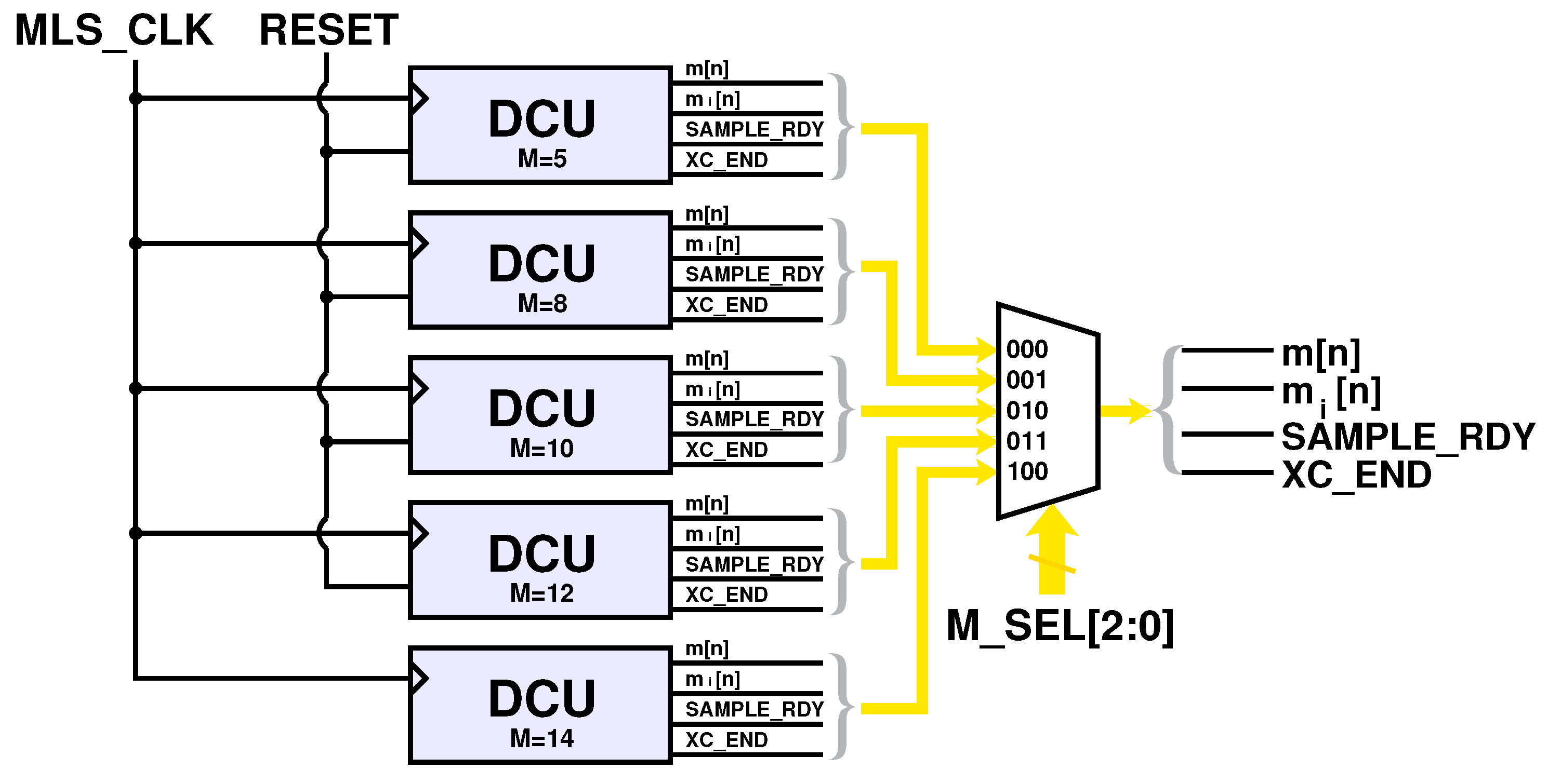
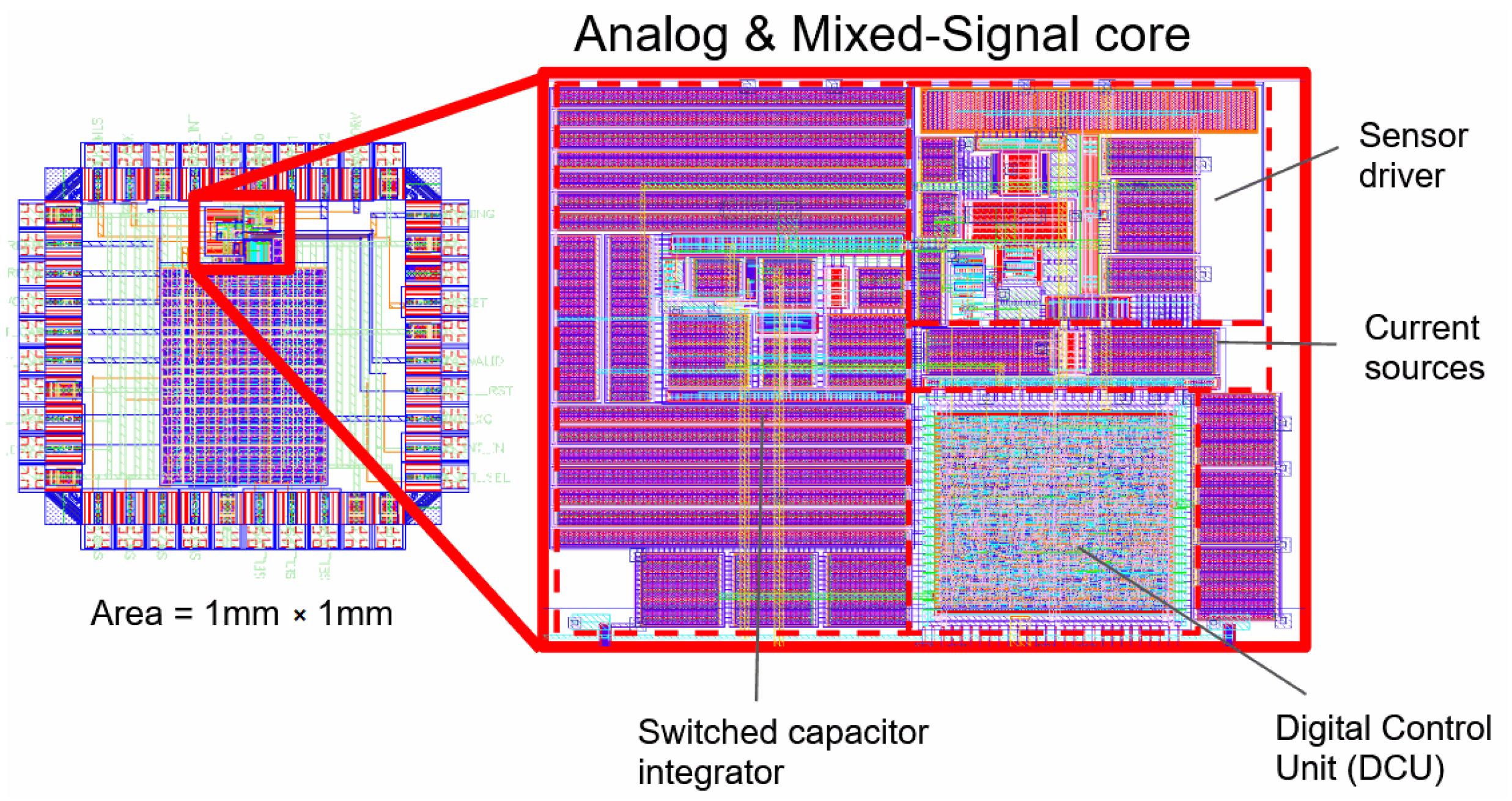
- Digital Control Unit (DCU): This unit generates two MLS sequences, namely m and mi, expressed here as arrays. More specifically, m is a standard MLS, whereas mi replicates m with an i start index that is incremented at every completion of m. The clock frequency of the DCU is the same as that of the MLS, i.e., . The M number of binary symbols is selected by the user through the M_SEL configuration word. The DCU is also responsible for the generation of the SAMPLE_RDY and XC_END control signals;
- AFE (analog front end): This is a charge pump-based front-end circuit for the SUT. It drives the sensor with a pseudo-random binary current signal of amplitude. This current signal is generated from the m sequence. The output of the AFE is the voltage across the sensor in response to the binary current;
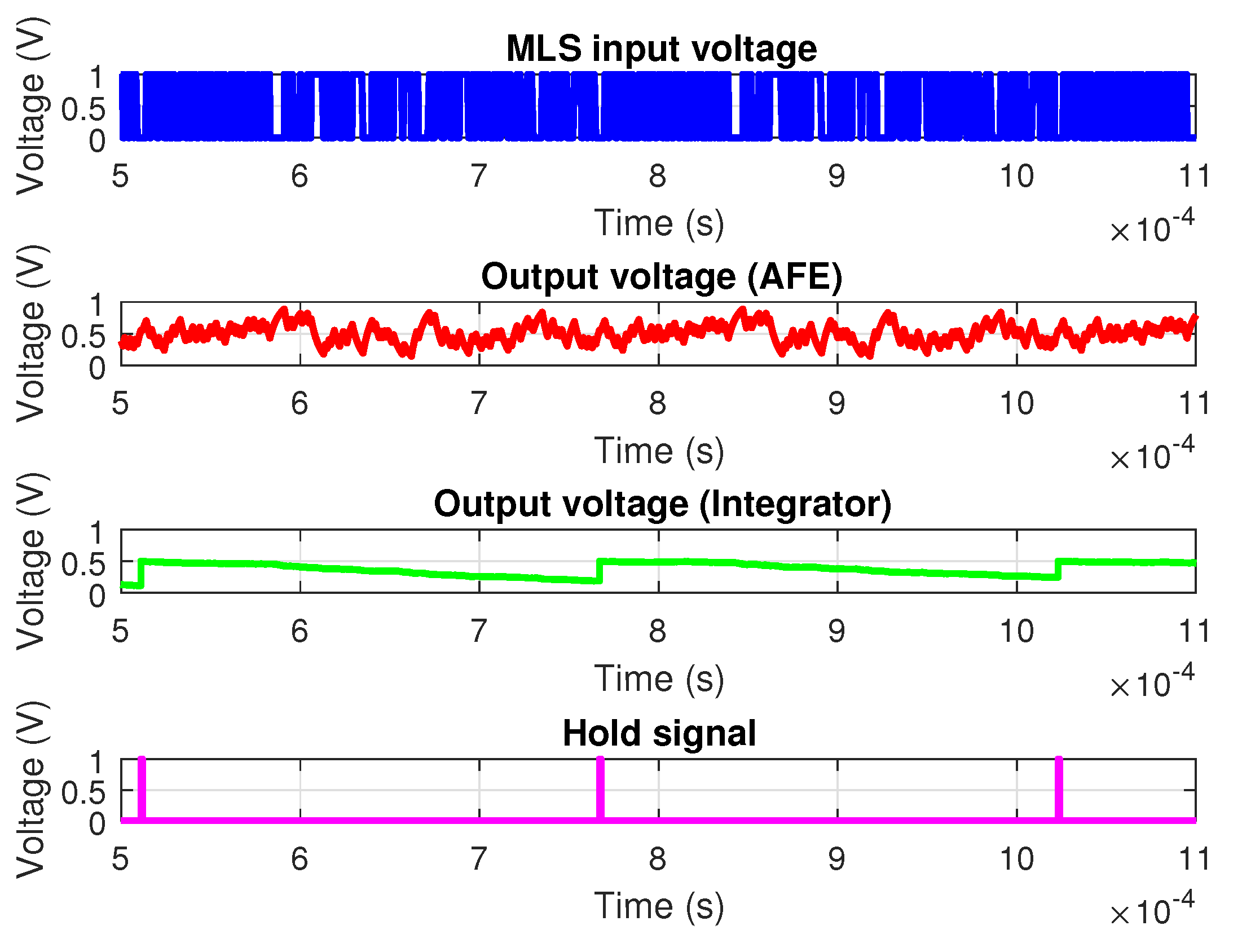
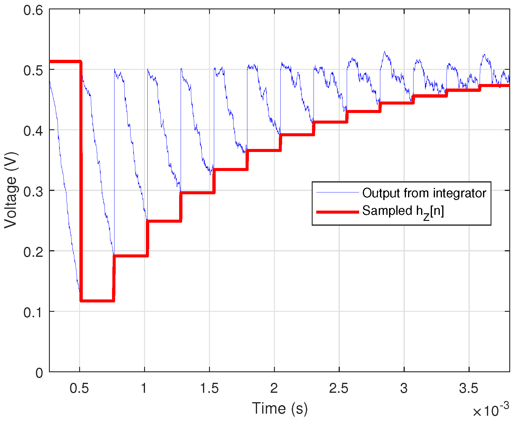
- Switched-Capacitor Integrator: This integrates the voltage into the discrete time. Its clock signal is provided through the INT_CLK input port and it has the same clock frequency as the MLS, i.e., . The integrator has the option to change the gain of the integration through the S configuration word. Moreover, the sign of the integration can be changed through the SGN binary input. This feature is essential in order to properly implement the cross-correlation operation in an analog fashion. Regarding the HOLD input, when set to 1, the integrator stops its operation while maintaining the stored value. The integrator’s output voltage, , is the output of the system and it is sampled by an external ADC at a lower sample rate as the SAMPLE_RDY signal goes higher.
3. Circuit Design
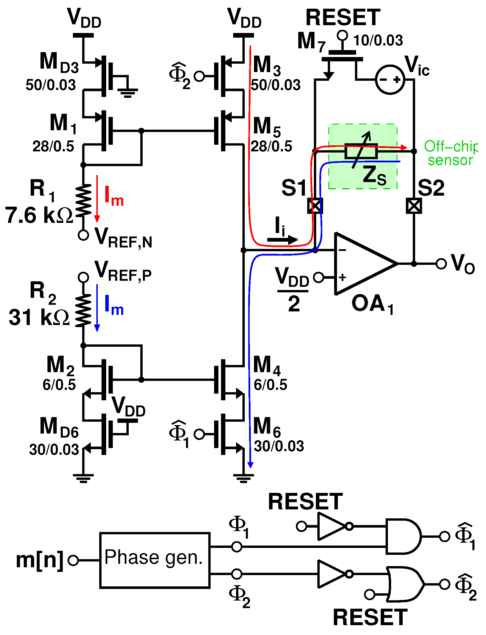
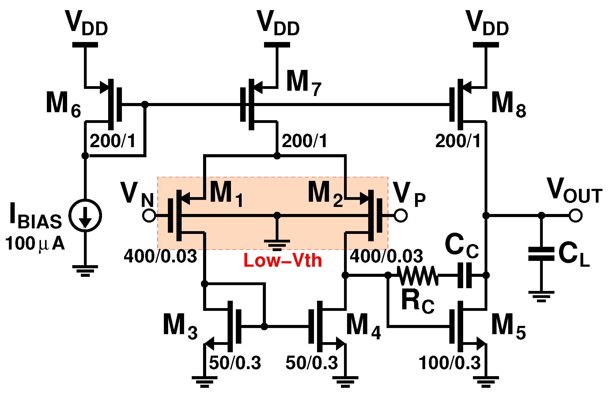
3.1. Analog Front End (AFE)
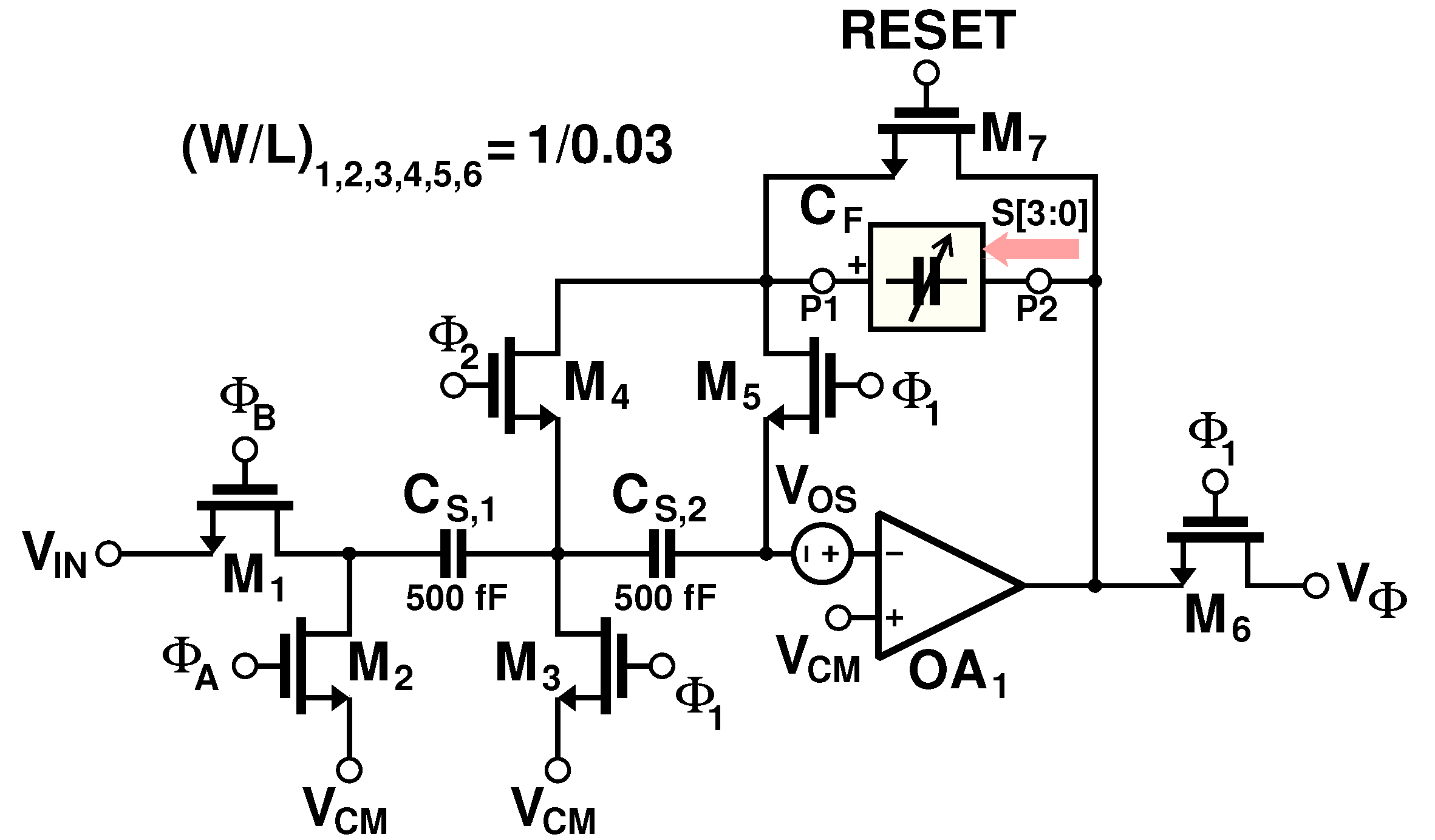
3.2. Switched-Capacitor Integrator
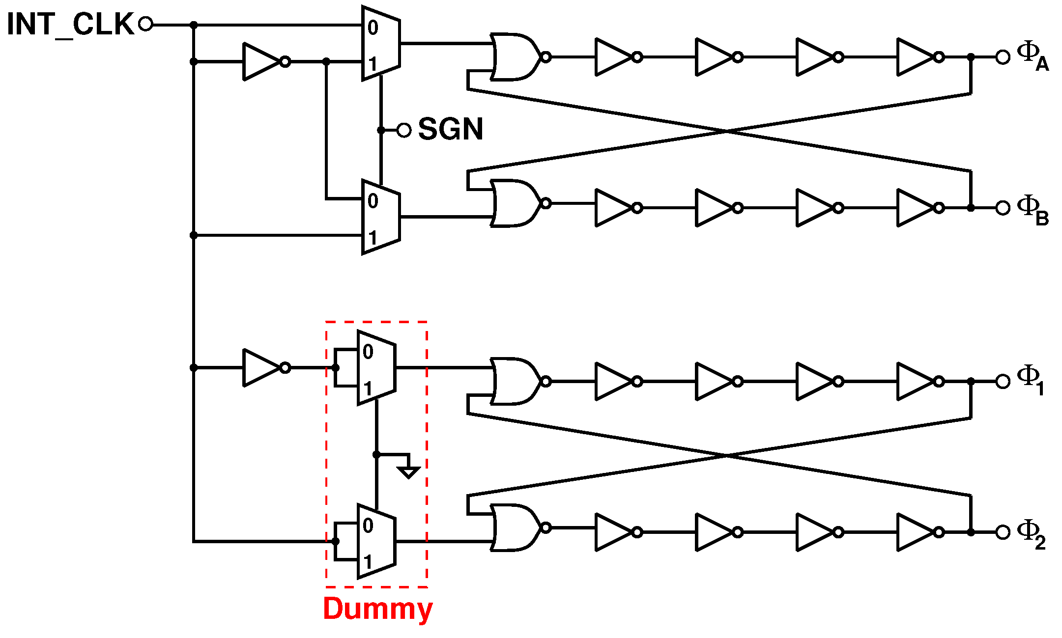
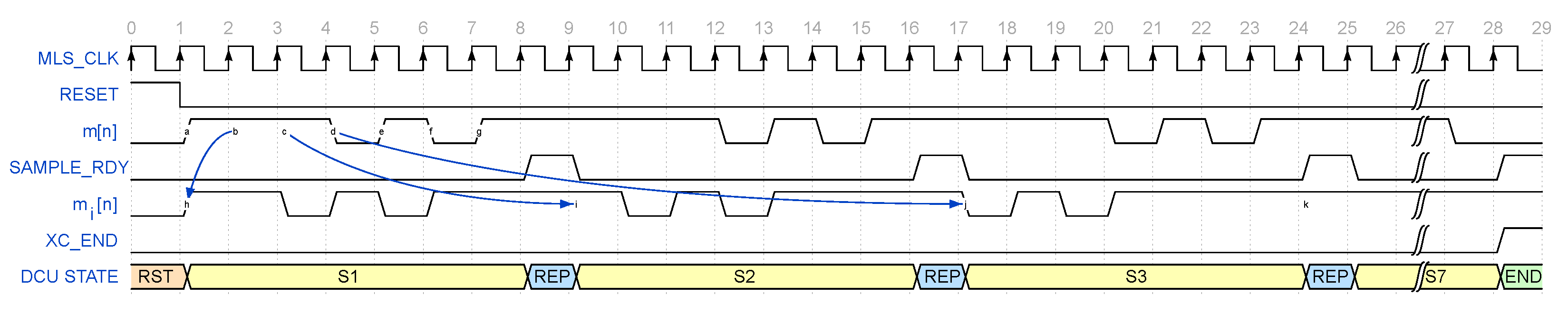
3.3. Digital Control Unit (DCU)
3.4. Noise Estimation
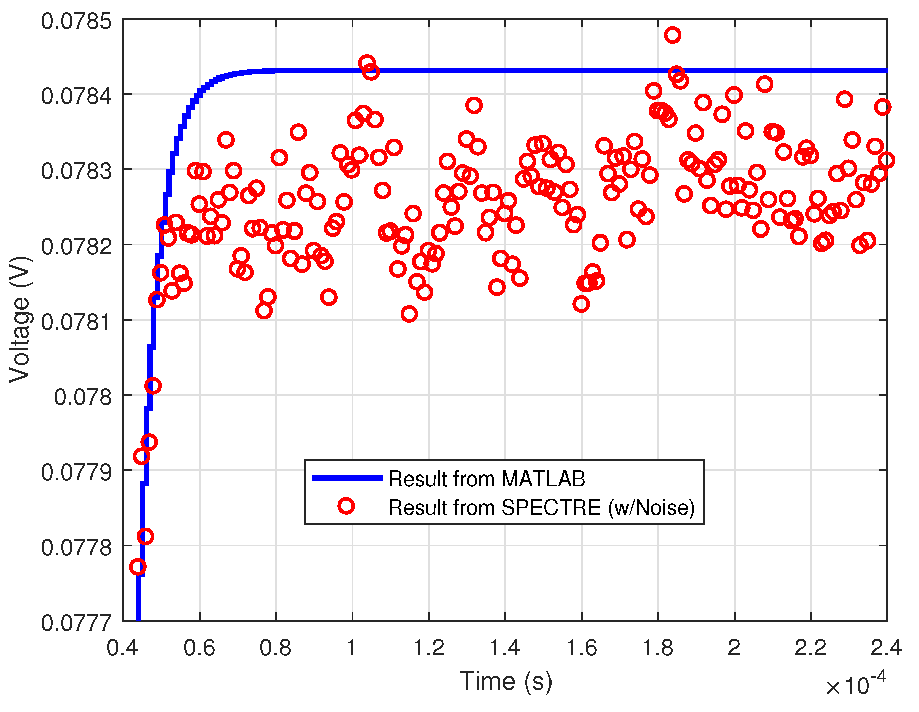
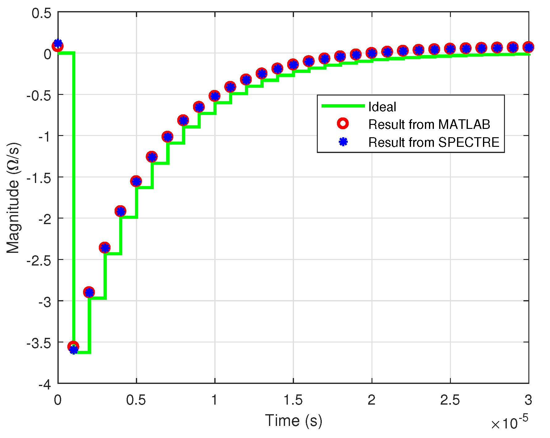
4. Simulation Results
5. Conclusions
Author Contributions
Funding
Conflicts of Interest
Abbreviations
| ADC | analog-to-digital converter |
| AFE | analog front end |
| CMOS | complementary metal-oxide semiconductor |
| DCU | digital control unit |
| EIS | electrical impedance spectroscopy |
| EpM | energy per measurement |
| FD-SOI | fully depleted silicon on insulator |
| GBW | gain-bandwidth product |
| IR | impulse response |
| LFSR | linear feedback shift register |
| LTI | linear time-invariant |
| MLS | maximum-length sequence |
| MOSFET | metal-oxide-semiconductor field-effect transistor |
| MOX | metal oxide |
| PM | phase margin |
| PRBS | pseudo-random binary sequence |
| RAM | random access memory |
| SNR | signal-to-noise ratio |
| SUT | sensor under test |
References
- Bianchi, D.; Ferrari, G.; Rottigni, A.; Sampietro, M. CMOS Impedance Analyzer for Nanosamples Investigation Operating up to 150 MHz with Sub-aF Resolution. IEEE J. Solid-State Circuits 2014, 49, 2748–2757. [Google Scholar] [CrossRef]
- Xu, J.; Hong, Z. Low Power Bio-Impedance Sensor Interfaces: Review and Electronics Design Methodology. IEEE Rev. Biomed. Eng. 2022, 15, 23–35. [Google Scholar] [CrossRef]
- Beohar, N.; Malladi, V.N.K.; Mandal, D.; Ozev, S.; Bakkaloglu, B. Online Built-In Self-Test of High Switching Frequency DC–DC Converters Using Model Reference Based System Identification Techniques. IEEE Trans. Circuits Syst. Regul. Pap. 2018, 65, 818–831. [Google Scholar] [CrossRef]
- Islam, S.M.R.; Park, S.Y. Precise Online Electrochemical Impedance Spectroscopy Strategies for Li-Ion Batteries. IEEE Trans. Ind. Appl. 2020, 56, 1661–1669. [Google Scholar] [CrossRef]
- Radogna, A.V.; Capone, S.; Francioso, L.; Siciliano, P.A.; D’Amico, S. Performance Analysis of an MLS-Based Interface for Impulse Response Estimation of Resistive and Capacitive Sensors. IEEE Trans. Circuits Syst. Regul. Pap. 2022, 69, 3666–3678. [Google Scholar] [CrossRef]
- Kassanos, P.; Triantis, I.F.; Demosthenous, A. A CMOS Magnitude/Phase Measurement Chip for Impedance Spectroscopy. IEEE Sens. J. 2013, 13, 2229–2236. [Google Scholar] [CrossRef]
- Shumba, A.T.; Montanaro, T.; Sergi, I.; Fachechi, L.; De Vittorio, M.; Patrono, L. Leveraging IoT-Aware Technologies and AI Techniques for Real-Time Critical Healthcare Applications. Sensors 2022, 22, 7675. [Google Scholar] [CrossRef] [PubMed]
- Ferrari, G.; Bianchi, D.; Rottigni, A.; Sampietro, M. 17.4 CMOS impedance analyzer for nanosamples investigation operating up to 150 MHz with Sub-aF resolution. In Proceedings of the 2014 IEEE International Solid-State Circuits Conference Digest of Technical Papers (ISSCC), San Francisco, CA, USA, 9–13 February 2014; pp. 292–293. [Google Scholar] [CrossRef]
- Cheon, S.I.; Kweon, S.J.; Kim, Y.; Koo, J.; Ha, S.; Je, M. An Impedance Readout IC with Ratio-Based Measurement Techniques for Electrical Impedance Spectroscopy. Sensors 2022, 22, 1563. [Google Scholar] [CrossRef]
- Crescentini, M.; Bennati, M.; Tartagni, M. A High Resolution Interface for Kelvin Impedance Sensing. IEEE J. Solid-State Circuits 2014, 49, 2199–2212. [Google Scholar] [CrossRef]
- Luciani, G.; Crescentini, M.; Romani, A.; Chiani, M.; Benini, L.; Tartagni, M. Energy-Efficient PRBS Impedance Spectroscopy on a Digital Versatile Platform. IEEE Trans. Instrum. Meas. 2021, 70, 6501912. [Google Scholar] [CrossRef]
- Radogna, A.V.; D’Amico, S.; Capone, S.; Francioso, L. A Simulation Study of an Optimized Impedance Spectroscopy Approach for Gas Sensors. In Proceedings of the 2019 IEEE 8th International Workshop on Advances in Sensors and Interfaces (IWASI), Otranto, Italy, 13–14 June 2019; pp. 142–147. [Google Scholar] [CrossRef]
- Rife, D.D.; Vanderkooy, J. Transfer-Function Measurement with Maximum-Length Sequences. J. Audio Eng. Soc. 1989, 37, 419–444. [Google Scholar]
- Radogna, A.V.; Capone, S.; Francioso, L.; Siciliano, P.A.; D’Amico, S. A 296 nJ Energy-per-Measurement Relaxation Oscillator-Based Analog Front-End for Chemiresistive Sensors. IEEE Trans. Circuits Syst. Regul. Pap. 2021, 68, 1123–1133. [Google Scholar] [CrossRef]
- Nagaraj, K.; Vlach, J.; Viswanathan, T.; Singhal, K. Switched-capacitor integrator with reduced sensitivity to amplifier gain. Electron. Lett. 1986, 22, 1103. [Google Scholar] [CrossRef]
- Im, S.; Park, S.G. A 154-μW 80-dB SNDR analog-to-digital front-end for digital hearing aids. Analog Integr. Circuits Signal Process. 2016, 89, 383–393. [Google Scholar] [CrossRef]
- Boni, A.; Giuffredi, L.; Pietrini, G.; Ronchi, M.; Caselli, M. A Low-Power Sigma-Delta Modulator for Healthcare and Medical Diagnostic Applications. IEEE Trans. Circuits Syst. Regul. Pap. 2022, 69, 207–219. [Google Scholar] [CrossRef]
- Xu, J.; Harpe, P.; Van Hoof, C. An Energy-Efficient and Reconfigurable Sensor IC for Bio-Impedance Spectroscopy and ECG Recording. IEEE J. Emerg. Sel. Top. Circuits Syst. 2018, 8, 616–626. [Google Scholar] [CrossRef] [Green Version]


| Parameter | Value |
|---|---|
| DC Gain | 60 dB |
| Gain-Bandwidth Product (GBW) | 105 |
| Phase Margin (PM) | 53 Deg |
| [10] | [9] | [6] | [18] | This Work | |
|---|---|---|---|---|---|
| Approach | Frequency-based (ΔΣ demodulation) | Frequency-based (magnitude/real part measurement) | Frequency-based (magnitude/phase measurement) | Frequency-based (MLS/DMLS + read-out, DSP not included) | Time-based (MLS + analog cross-correlation) |
| CMOS Process | 0.35 μm | 180 nm | 0.35 μm | 180 nm | 28 nm FD-SOI |
| Chip area | 9 mm2 | N/A | 0.4 mm2 | N/A | 0.034 mm2 (core) |
| Tested impedance | 68 Ω ‖ 1 μF | 200 Ω + (5 kΩ ‖ 45 nF) | Equivalent circuit of the electrode/tissue impedance | 100 Ω ‖ (100 Ω + 220 nF) | 50 kΩ ‖ 100 pF |
| Stimulus generator | Yes | No | No | Yes | Yes |
| Max tested frequency | 16 kHz | 1 MHz | 100 kHz | 125 kHz | 500 kHz (capable of measuring up to 50 MHz) |
| Measured points | 1 | 1 | 1 | 63 | 255 (capable of measuring up to 2 points) |
| Max Error | 0.0166 % (INL) | 0.3% (magnitude error, simulated) | 1.15% (magnitude error) | >10% (resistor error) | 0.0177% (RMS on entire curve, simulated) |
| Max power consumption | 5.8 mW | 0.513 mW | 21 mW | 0.155 mW | 0.420 mW |
Publisher’s Note: MDPI stays neutral with regard to jurisdictional claims in published maps and institutional affiliations. |
© 2022 by the authors. Licensee MDPI, Basel, Switzerland. This article is an open access article distributed under the terms and conditions of the Creative Commons Attribution (CC BY) license (https://creativecommons.org/licenses/by/4.0/).
Share and Cite
Radogna, A.V.; Capone, S.; Francioso, L.; Siciliano, P.A.; D’Amico, S. A 177 ppm RMS Error-Integrated Interface for Time-Based Impedance Spectroscopy of Sensors. Electronics 2022, 11, 3807. https://doi.org/10.3390/electronics11223807
Radogna AV, Capone S, Francioso L, Siciliano PA, D’Amico S. A 177 ppm RMS Error-Integrated Interface for Time-Based Impedance Spectroscopy of Sensors. Electronics. 2022; 11(22):3807. https://doi.org/10.3390/electronics11223807
Chicago/Turabian StyleRadogna, Antonio Vincenzo, Simonetta Capone, Luca Francioso, Pietro Aleardo Siciliano, and Stefano D’Amico. 2022. "A 177 ppm RMS Error-Integrated Interface for Time-Based Impedance Spectroscopy of Sensors" Electronics 11, no. 22: 3807. https://doi.org/10.3390/electronics11223807
APA StyleRadogna, A. V., Capone, S., Francioso, L., Siciliano, P. A., & D’Amico, S. (2022). A 177 ppm RMS Error-Integrated Interface for Time-Based Impedance Spectroscopy of Sensors. Electronics, 11(22), 3807. https://doi.org/10.3390/electronics11223807