1. Introduction
Engineering graduates in industrial technologies are professionals with the ability to efficiently plan, design, implement, operate, maintain, and control organizations made up of people, materials, equipment, and information to ensure the best performance of systems related to the production and administration of goods and services [
1]. These professionals must act as one of the main factors of industrial development and respond to the needs imposed by a modern society where classic design techniques must be combined with new technologies and all the necessary restrictions to conserve the environment [
2]. For this reason, their training includes knowledge of various branches, such as mechanical, electrical, materials, systems and automatic engineering, electronic engineering, installation and construction, design and production, energy, environment, direction, and management, etc., which allows them to be at the service of society applications in which these branches of knowledge must be suitably combined [
3]. It is a challenge to integrate and unite this knowledge, giving students a comprehensive perspective that requires combining multiple knowledge [
4] and facing a practical technical challenge [
5] under the supervisor guidance, and this is the aim of degree final projects (DFP).
The present scenario in electrical power distribution and consumption [
6] increases the motivation to extend the content related to power electronic converters connected to electrical grids in the subjects of Power Electronics and the DFP of the Degree in Engineering in Industrial Technologies. The design of converters requires combining knowledge in different disciplines such as electricity, power electronics, control systems, and digital electronics, among others [
7]. To build a power converter successfully, students traditionally have developed prototypes based on a bridge rectifier and a boost converter with an analog-integrated circuit (IC) control (e.g., UC3854 [
8]) that includes the necessary active components to implement the control loops and drivers and guarantee well-established configuration to acquire signals and to define the controller. With the IC and following the technical notes of the manufacturers, students built prototypes covering the expected specifications. However, these technologies are being overtaken by the latest trends in power converters developed in the last decade [
9]. Updating the technology to bridgeless topologies [
10], wide bandgap power devices [
11], and digital control [
12] increases the number of tasks the time required to be performed to successfully complete a prototype. Therefore, this modern and new approach can become a challenge for students and teachers, due to the time limitations, in terms of available credits to tackle the task completely and effectively [
13,
14]. In this new context, the programming of control in a device is considered a bottleneck because students must learn and/or delve into programming languages and become familiar with the devices (microcontrollers or field programmable gate arrays, FPGA) and the software used. Here, the replacement of this task by rapid prototyping techniques allows the student to connect the simulation models with the automatic programming of the device used, eliminating the need-to-know programming languages, delve into the device used, and spend time debugging errors in the code [
15,
16]. Thus, it allows them to focus their efforts on other project tasks that they are less familiar with, such as building the converter or choosing its components.
Project-based learning (PBL) [
17,
18,
19] seems the most appropriate learning environment to develop these DFPs because its effectiveness in teaching power electronics is widely contrasted [
20,
21,
22,
23]. Therefore, the teaching experience presented in this work uses PBL to make modern prototypes of digitally controlled power electronic converters in the DFP in Engineering in Industrial Technologies at the University of Cantabria [
24]. Its objective is to present an adaptive proposal to students where, based on their experience and knowledge, a challenge is posed that allows them to put into practice and balance the knowledge and skills acquired in previous subjects. To do this, students become familiar with the topologies of power factor correctors (PFC), their modes of operation [
25], the design, modeling, and validation of digital controllers, minimizing the skills required on digital control devices architecture and programming, using a LAUNCHXL-F28379D board from Texas Instruments (TI) [
26] and PLECS
® code generation tool from Plexim [
27]. The design of the laboratory prototype is carried out, starting from a reference design, e.g., [
28], designing and selecting the components of the power stages (magnetic, semiconductor, etc.), voltage and current sensing, signal conditioning, as well as the printed circuit boards (PCB) and, finally, its associated budget was validated. This work has been organized as follows.
Section 2 describes the methodology followed in the experience.
Section 3 presents the results and the discussion, showing a concrete example of a bridgeless totem-pole PFC developed. At last,
Section 4 includes the main conclusions of the work.
2. Materials and Methods
Building a bridgeless PFC prototype following the state-of-art power converters requires the student to deepen their knowledge of digital electronics, analog electronics, electricity, signal processing, electronic instrumentation, power electronics, programming languages, and computer technologies because it includes:
- I.
The modeling of the converter using MATLAB®/Simulink®.
- II.
The design of the device control and its modeling to debug errors.
- III.
The programming of the control in a digital device (FPGA or microcontroller), which required becoming familiar with the device architecture, functionalities and operation, the programming languages (VHDL or C) and development environments (Vivado®, ISE®, or Code Composer Studio™).
- IV.
The design and construction of the power converter (including the selection and construction of components and the design and construction of auxiliary circuits and PCBs).
- V.
The full system checks.
The bottlenecks that the students faced were usually focused on the programming of the digital devices, component selection, and the prototyping of the converter. Although this methodology used guaranteed complete learning, compliance with the limited deadlines for the delivery of the DFP was complex and the real workload exceeded the planned. For this reason, the methodology is revisited, allowing the tasks to be undertaken with tighter execution times and autonomous work outside the laboratory while balancing the integration of the required skills for each student.
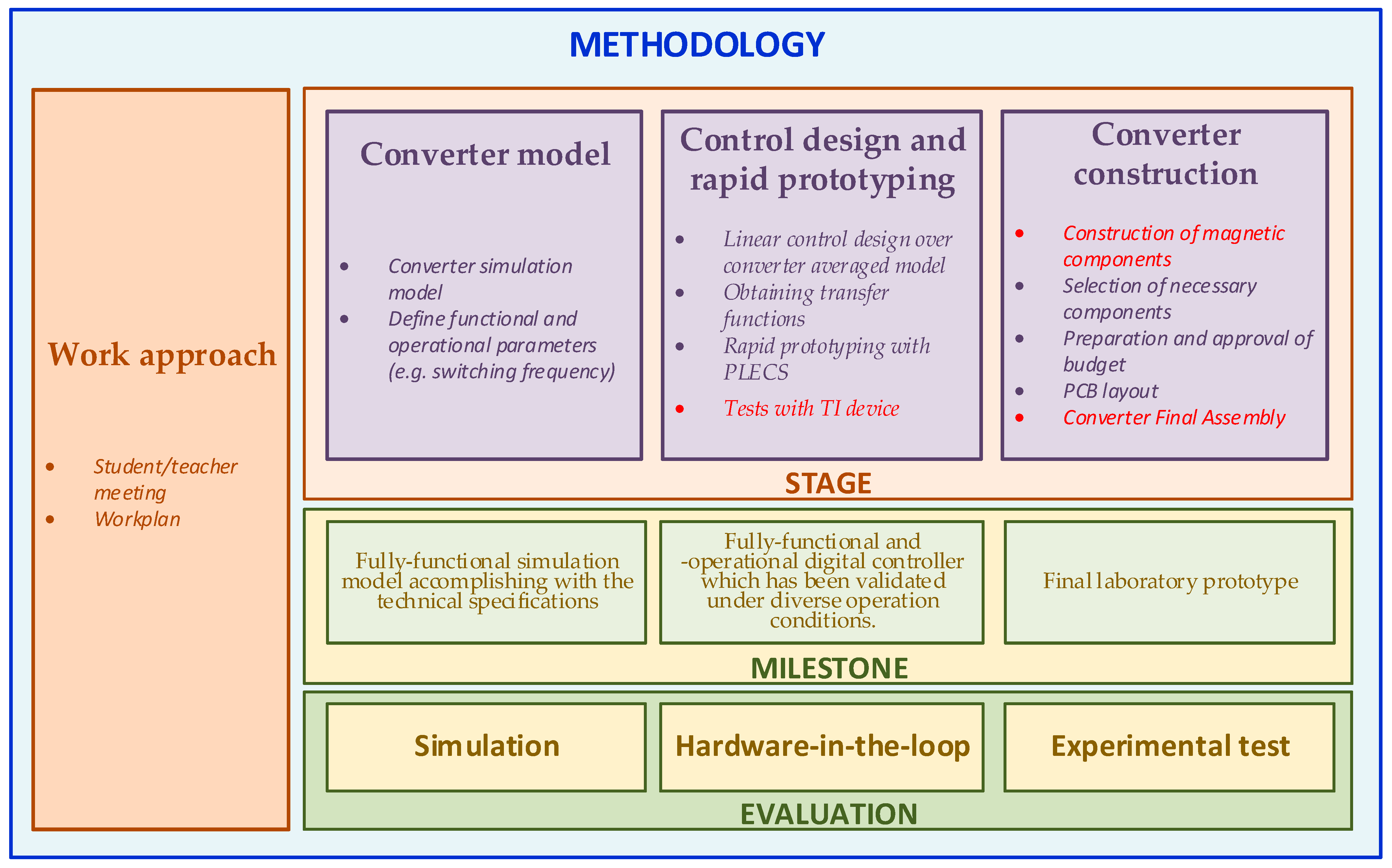
Figure 1 presents the basic scheme of the teaching–learning methodology used, detailing the labor to be developed and how to evaluate it. The tasks that must be realized in person in the laboratory have been marked in red. Other tasks, presented with purple background, can be performed at home with the online supervision of the instructors whenever necessary.
2.1. Work Approach
After the student decides to get involved in the DFP with the power electronics laboratory (PEL), an individualized workplan is defined. Across the power converter topologies being used in researching and development activities, interests and planned deadline, a certain power converter is selected. The target of this individualized workplan is to (1) accomplish the required tasks in the established schedule; (2) develop their skills facing the practical challenge; (3) balance previously acquired knowledge; and (4) get out of their comfort zone and face challenges close to the professional environment where they will develop. Once the work plan has been agreed upon along with the follow-up of the tasks as defined in
Figure 1, the student is given access to the laboratory and receives the material necessary to carry out the task.
2.2. Converter Model
The students receive the technical specifications of the converter.
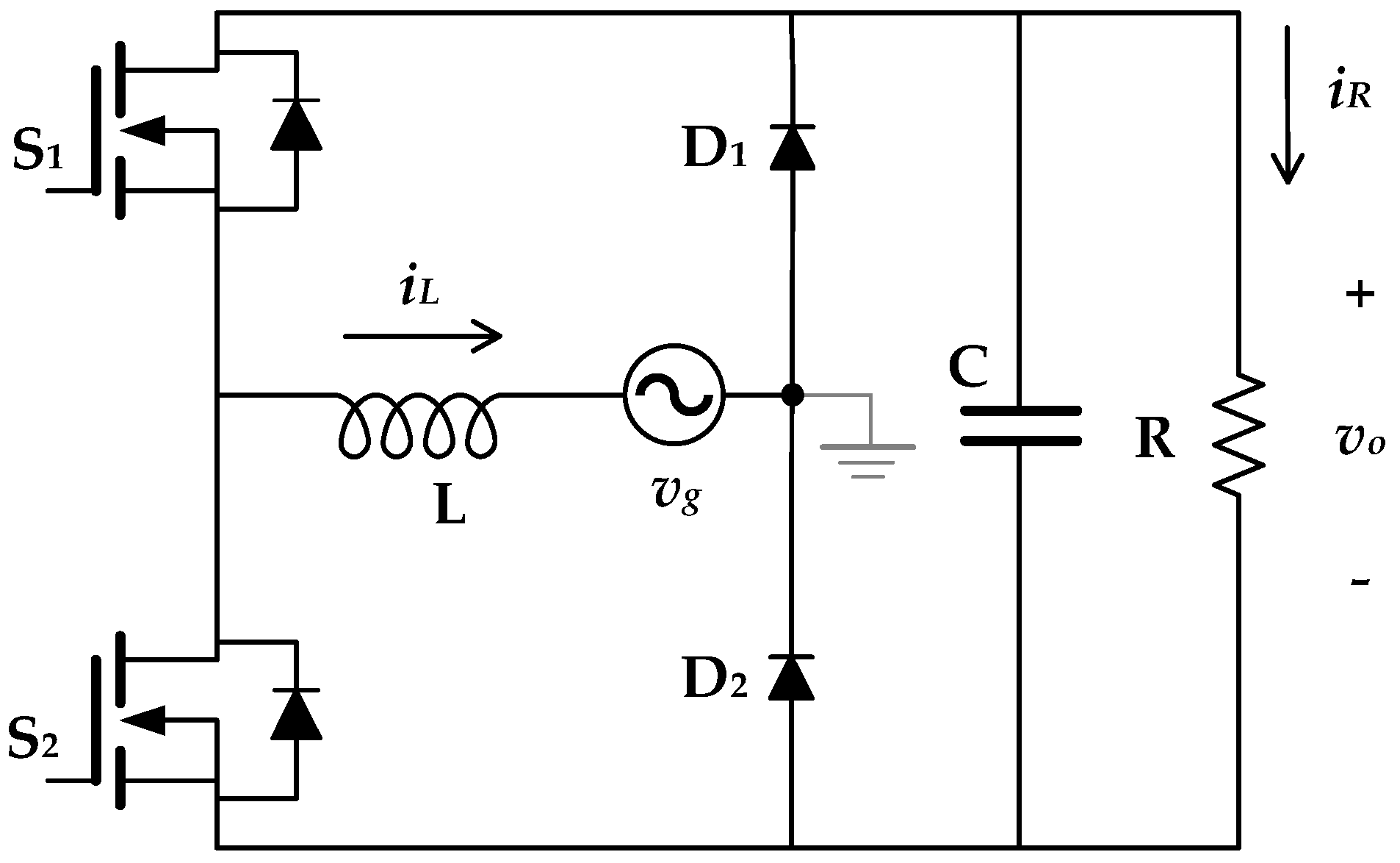
Table 1 shows an example of the specifications of a totem-pole converter (
Figure 2), made by one of the students following this methodology.
The students have received training on power converter modeling techniques in a compulsory subject, Extension of Electronics, and in another elective subject, Electronic Power Conversion. This knowledge is used in this project to translate the technical specifications to functional and operational characteristics to be implemented. From these, they develop a simulation model using the PLECS
® tool in MATLAB
®, where the power converter functionalities can be varied through design parameters to become familiar with its behavior and allow including the effects of the increase in temperature due to the dissipated power and non-linearities of the magnetic elements [
29].
Additionally, for the choice of the switching frequency of the converter, the students take into account factors such as the losses due to switching, the characteristics of analog-to-digital conversion (ADC), and pulse width modulation (ePWM) subsystems of the LAUNCHXL-F28379D microcontroller. Initially, the ePWM is presented as the sampler of the controller output signal. The generation of PWM results from the comparison of the modulating signals, resulting from the control action that is acquired at the beginning of each switching period to obtain the ePWM signal, according to [
20]. Additionally, the size of the magnetics and the grid filter according to [
30] is worked.
As a milestone for this first stage, a fully functional simulation model accomplishing with the technical specifications is given. From the qualitative evaluation at this stage, e.g., startup issues, sensitivity to parameters and protections, considerations are given to address these issues in subsequent stages.
The model is evaluated based on analyzing the simulation results obtained, which are used to verify the design of the control and the designed converter.
2.3. Control Design and Rapid Prototyping
To design the controller, students follow the technique described in [
20], where the input current regulator is designed from the identification of the plant of the boost converter, specifying the bandwidth of the loop of current control. Once the current control has been defined, they design the output voltage control loop by modeling the converter as an equivalent variable resistor at the input and a power source at the output. As a result of this task, the students obtain the transfer functions of the two regulators in the frequency domain. To implement the designed control, it is avoided to delve into the architecture of the microcontroller and its programming using the PLECS
® rapid prototyping tool. In it, the control can be configured using the blocks provided by PLECS
® (
Table 2) for use in the microcontroller.
The novelty of the device used compared to previous versions, i.e., the control card F28335, lies in the fact that the need to build some elements of the system is eliminated. This is the case with the digital-to-analog converter (DAC), which in previous versions required an external connection through a general-purpose output (GPIO).
The methodology to implement the transfer functions in the tool is not specific to PLECS® but is inherited from MATLAB®/Simulink®. To configure the transfer functions of the designed control, students must create enabled subsystems to include a block that allows them to define the transfer function in the frequency domain.
PLECS® student licenses are provided by Plexim through teacher-distributed codes. They have a duration of one year and are subsequently renewable through a new code. In this way, students can work on their projects from home without the need for lab assistance while debugging and improving their designs.
The PLECS® environment has two programs: PLECS® Blockset, which integrates with an updated version of MATLAB®, and PLECS® Standalone, which allows for working in an independent environment. Both options can be used for automatic code generation and are available for different operating systems. In either case, installing the tool is easy. However, in this experience, the PLECS® Blockset version was chosen, because MATLAB® is available to students using their corporate credentials and they handle it with ease due to its use in previous subjects. To further facilitate the task, the teachers present a step-by-step guide to the students on how to undertake this installation successfully and simple examples are practiced, verifying the operation of the device and PLECS®. For example, a simple but very useful first practice consists of configuring the blinking of one of the LEDs that include the device using the scheme shown within a subsystem. The objective of this practice is threefold: (1) to familiarize with the tool, (2) to verify the correct installation of the software and the operation of the hardware, and (3) to know the pin map of the device.
The milestone at this stage is the student having a fully functional digital controller which has been validated under diverse operation conditions.
For evaluation purpose, the proposed controller interacts with a HIL converter model in a FPGA which is provided by the instructors. Students program their LAUNCHXL-F28379D, using the PLECS® code generation tool, and verify the build by checking its operation alongside the FPGA.
2.4. Converter Construction
After verifying the design of the converter and its behavior with the control in simulation, some students reach the stage of building the prototype of the converter.
In the construction of the prototype, the students acquire experience in the design of magnetic components by building and characterizing the coil of the converter [
31,
32]. Reactive components are characterized by an LCR that allows direct current injection.
Regarding the choice of semiconductor elements, students must select the transistors that best suit their case to reduce capacities and parasitic inductances. For the control of the switching state of the power devices, a non-isolated driver is used, following the strategy presented in [
33].
The sensing of the voltages and currents of the circuit where control and protections act are performed through voltage dividers and current shunts, respectively. The signal conditioning circuits are designed using low-noise, thermal-drift, uni-rail operational amplifiers, and incorporate second-order anti-aliasing filters [
34,
35]. The designs aim to minimize the number of power supply units (PSUs) isolated from the laboratory prototype. The LAUNCHXL-F28379D has two differential analog inputs and sixteen single-ended ones. The latter is used in the acquisition of three prototype signals: input voltage, input current, and output voltage. The two gate signals necessary for the operation of the power converter are applied from the GPIO of the microcontroller. One of these signals, used for the branch switching at 65 kHz, is generated from a high-resolution ePWM block of the microcontroller, while the gate signal for the branch switching at 50 Hz is obtained through a digital output.
Finally, students design a PCB with trying to ensure the proper functioning of the laboratory prototype and facilitating its subsequent construction.
The milestone at this stage is having the final laboratory prototype.
To evaluate this stage, the final product that the students are expected to develop is a prototype of the converter controlled by the designed control. Behavior and robustness tests will be carried out on this prototype. The laboratory has an operational 3300 W CCM bidirectional PFC totem-pole unit that uses CoolSiC™, which is used as an example of good practice.
3. Results and Discussion
The realization of this adaptive experience began during the 2020–2021 academic year and continues over time. However, student work is performed in 6 months with a dedication of 4 h per day. This period is significantly lower than needed using the traditional methodology. This difference is mainly due to the introduction of the rapid prototyping tool, which allows students to focus on making a good converter design and delve into the handling of electronic instrumentation and practical skills. This allows rebalancing the competences acquired by the students, since it is not possible to go deeper with this level of detail in the subjects of power electronics included in the degree.
The contents worked are based on the use of practical methods in the laboratory as a teaching–learning method and the use of specific software and hardware that cannot be completely replaced by a virtual environment without compromising the advantages that a practical method offers the engineering student [
36]. The use of simulation software with student licenses that allows, in turn, rapid prototyping of these systems, makes the tasks more attractive for students, who can develop this part at their own pace at any time and place, eliminating the need for a permanent presence in the laboratory.
Although this new methodology began to be used during the COVID-19 pandemic and was a viable solution to the capacity limitations caused by health restrictions, this fact is anecdotal since the success of the proposal guarantees its continuity over time, establishing it as a benchmark to follow in the future.
3.1. Limitations
From the point of view of student work, the main problems related to designing and choosing system components. For example, difficulties have been found in defining low noise references of the control measurement circuits and drivers, in the choice of the appropriate length for the conductors that make them compatible with the frequency of the signals, and in the sizing of the Bootstrap capacitor for the branch that switches at 50 Hz, which must be different from the one used in the branches that work at tens of kHz. In addition, there were additional difficulties bottlenecking in the verification of the built prototype, e.g., in checking the welding points and the verification of the correct operation of each welded component.
As it is an individualized teaching experience, where the student works at their own pace, advised by the teachers, and the result is the construction of a real prototype of a power converter, which is subsequently documented for their DFP, interactions among students have been limited. This has two conditions: (1) It has not been possible to propose a work scheme where several students with different levels of knowledge and/or skills are worked together. (2) The number of students who have participated in it (<10) prevents presenting statistical results of student satisfaction or their grades.
To compare the teaching experience presented in this work, different proposals published in power electronics in recent years have been deepened. However, the proposals focus on hardware-in-the-loop emulators to develop controls of power electronics systems [
37,
38], simulation models [
39], and remote laboratories [
36,
40] to strengthen basic knowledge and methodologies based on the use of augmented reality [
41], which make the most of the multimedia resources and virtualization. Only the experience presented in [
42] uses an approach focused on the construction and testing of basic electronic circuits, concluding, the suitability of using blended teaching in these cases and how the strategy improved student scores. Therefore, it has not been possible to draw a fair comparison between them because their methodologies, objectives, and results were different.
3.2. Example of the Results Obtained
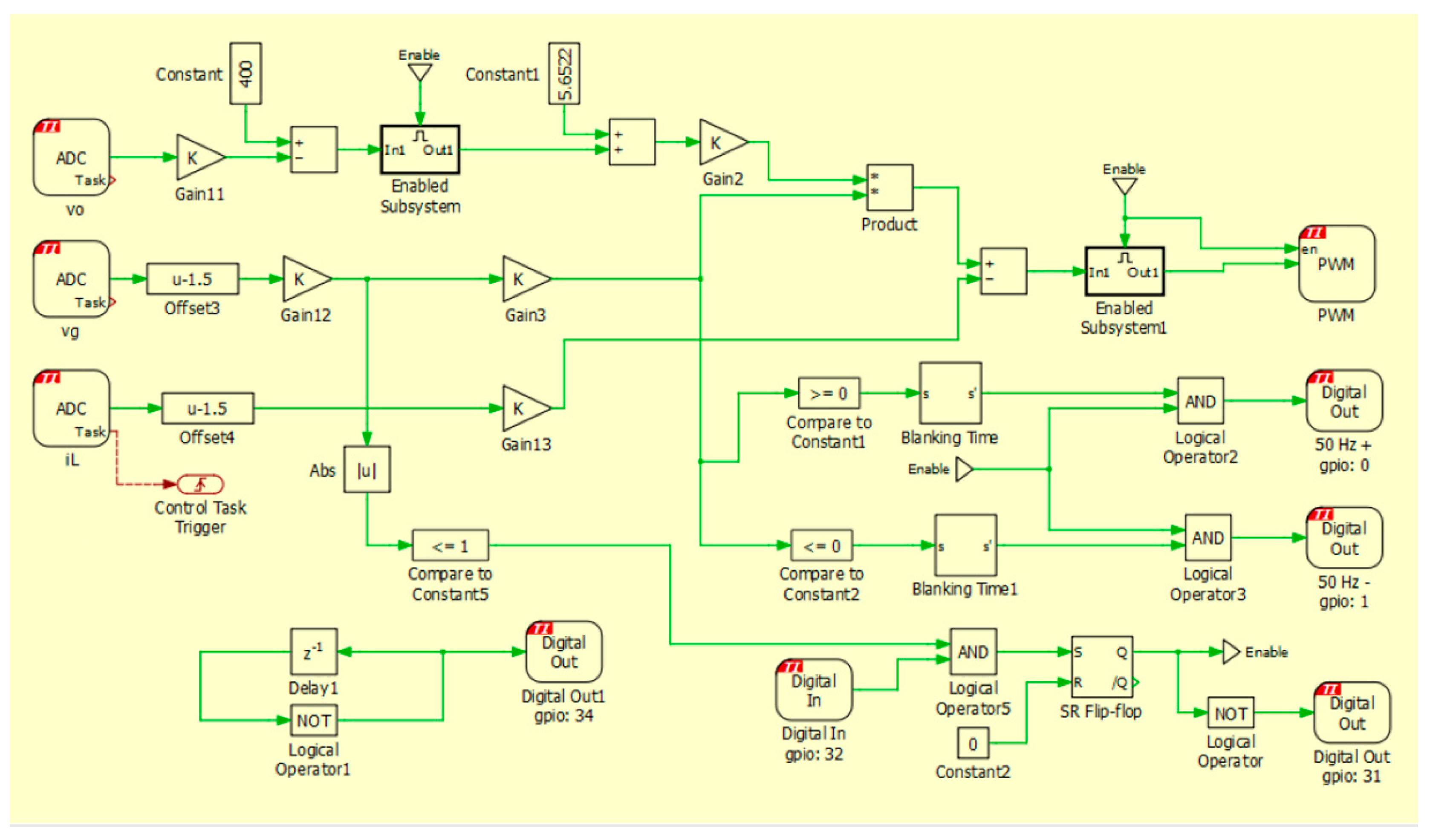
In the example, the students design and build a bridgeless totem-pole AC/DC rectifier converter and synthesize its digital controller, resulting in an adequate correction of the power factor and high efficiency. Initially, students design and simulate the power converter based on previous technical specifications (
Table 1) and its control in PLECS
®. As represented in
Figure 3, they have not only included the current and voltage control blocks in their design, but also security measures, such as the enabling of a high-frequency and low-frequency switching activation signal. The latter occurs when the peak value of the input voltage exceeds 200 V and the voltage crosses through zero, reducing the intensity peaks in the input current. In addition, a soft start of the input voltage by ramp has been designed.
The current regulator obtains a loop transfer function with a 0 dB crossover frequency at 6 kHz. The phase margin is 53°. For its part, the output voltage regulator is designed for the loop transfer function crosses 0 dB at 1 Hz. Output capacitor is calculated to obtain 10% output voltage ripple.
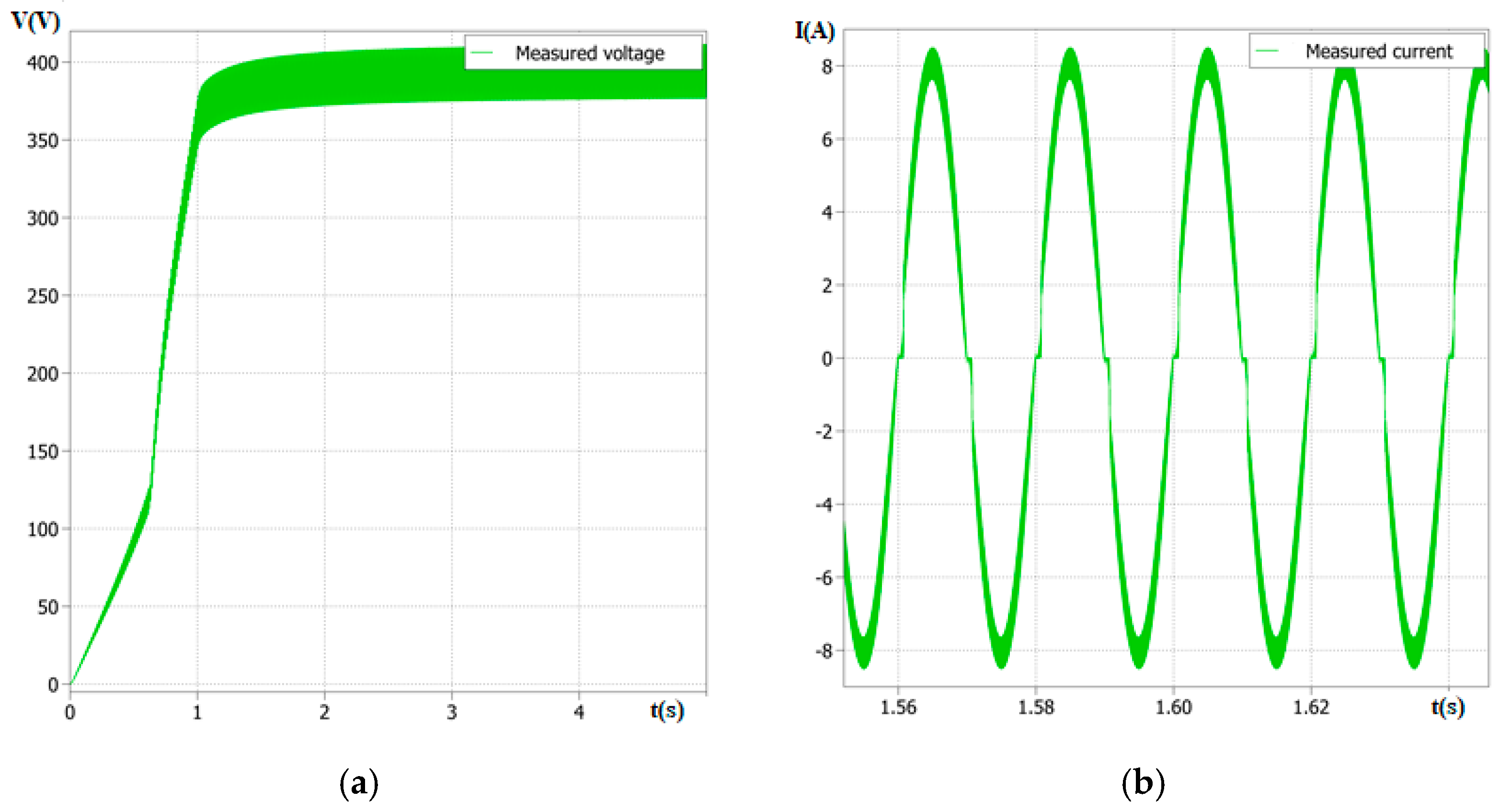
Figure 4 presents examples of simulation results of the digitally controlled converter, where the waveform of the output voltage of the soft start can be seen during the first second and its nominal value (400 V) stabilizes after 1.5 s (
Figure 4a). In addition,
Figure 4b holds up the input current in a steady state. The effect of the zero crossing of the positive half cycles due to the subsequent reconstruction of the input voltage from the polarity signal can be seen, given that at first that the input voltage to the converter is rectified before going to the sensing circuit, while the harmonic distortion of the current in the coil reaches 7%.
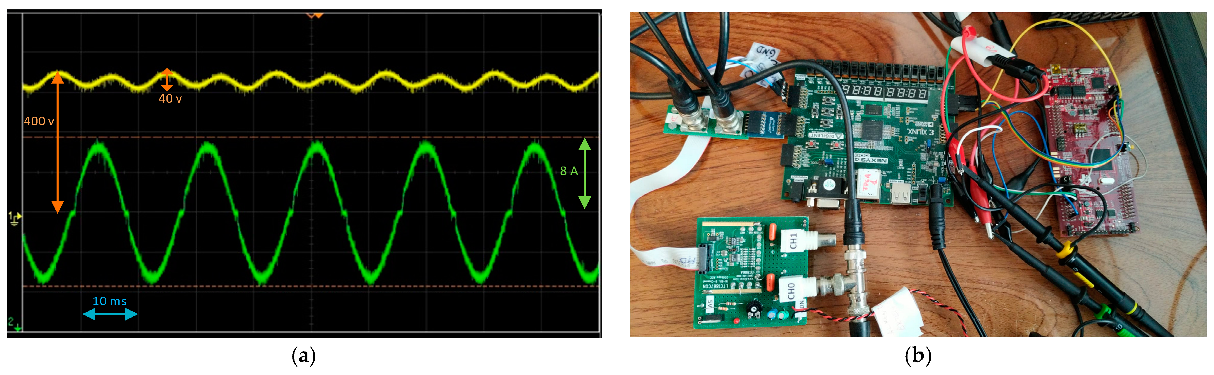
Figure 5 shows the verification of the control operation using a Nexys-4DDR FPGA and an ADC model DC806A that emulates a totem-pole converter using the HIL technique.
Figure 5b presents the details of the experimental set-up carried out to verify the control proposed in the LAUNCHXL-F28379D and analyze whether the response of the converter is as expected. The waveforms of the voltage and current are shown in
Figure 5a.
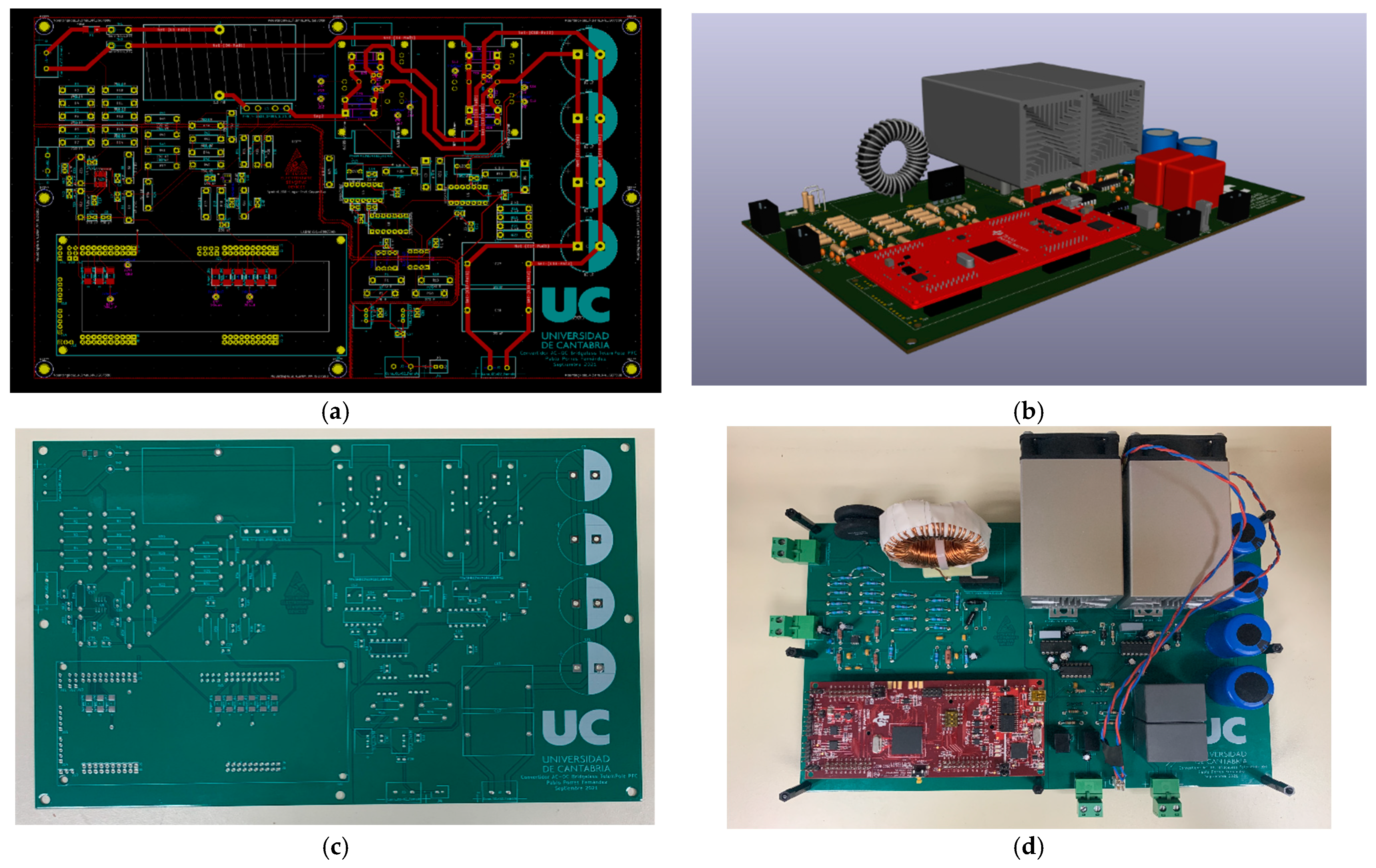
When the controller works correctly, students start the design of the PCB from the footprint of the designed and/or selected components using a design tool. They configure the PCB trying to optimize the space (
Figure 6a). This software has a 3D viewer that allows visualizing how their plate will finally look like and the physical distribution of the elements on it (
Figure 6b). Once the design has been verified by the teachers, the PCB is built (
Figure 6c) and, with it, the final prototype (
Figure 6d) welding of each component in the appropriate place.
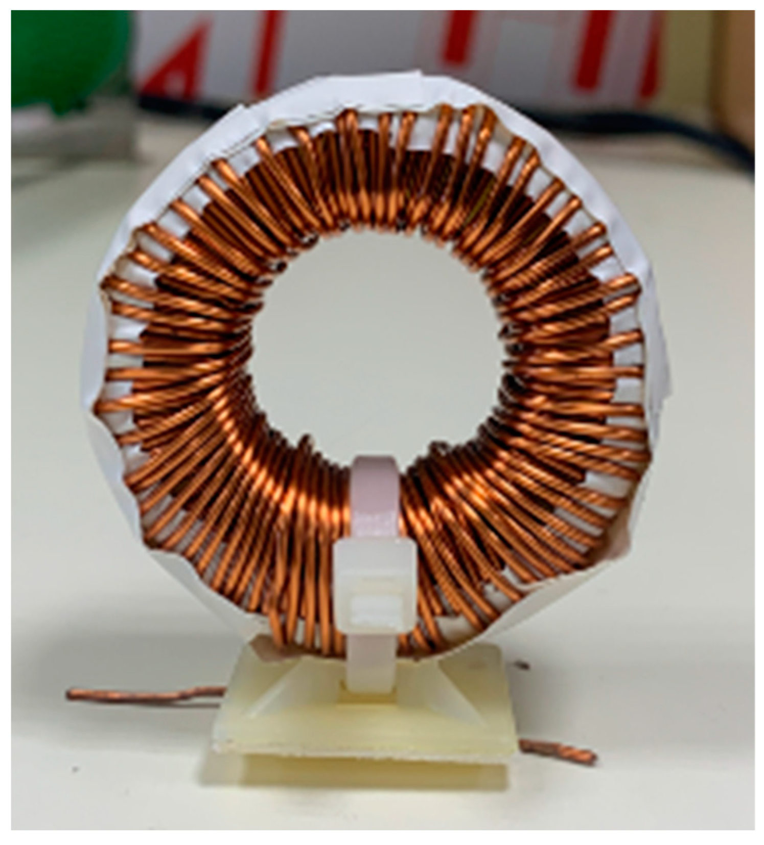
After validating the simulation results, the students design or select each component of the converter prototype, such as the coil in
Figure 7, which is characterized (
Table 3) in a precision LCR meter. Once all the necessary components have been selected, a budget is drawn up that is approved, before being executed, by the instructors.
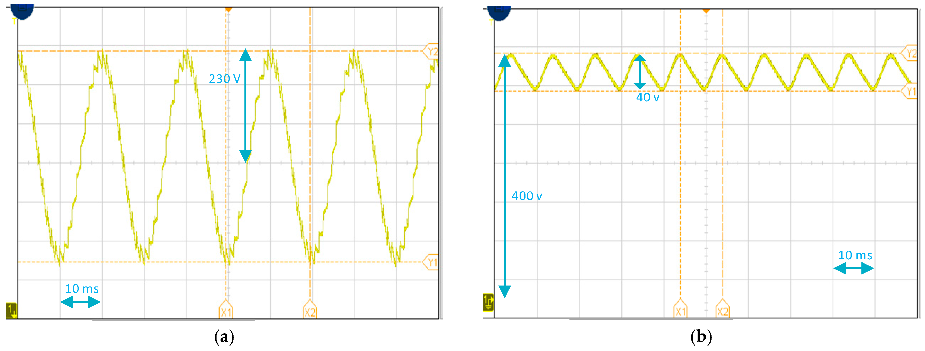
Finally, the complete assembly of the prototype is verified through controlled tests in the laboratory. The converter is powered by an Agilent 6813B AC source and its response is measured using a Keysight InfiniiVision DSOX3024T oscilloscope.
Figure 8 shows the experimental results obtained with oscilloscope captures of the input voltage of the converter (
Figure 8a), and output voltage (
Figure 8b).


