Abstract
The continuous high-frequency oscillation phenomenon of the MMC-HVDC system occurs frequently in practical engineering. How to design an effective oscillation suppression strategy based on the essential mechanism of continuous oscillation has not been sufficiently supported by theory. For this reason, this paper firstly analyzes the high-frequency oscillation characteristics of the MMC-HVDC system. On this basis, considering the influence of the control system time delay, the MMC high-frequency impedance model is established based on harmonic linearization. Thirdly, the dynamic interaction between the control system and the harmonic disturbance is analyzed, and the continuous oscillation mechanism of the MMC-HVDC system is revealed. Finally, a high-frequency oscillation suppression strategy is proposed, consisting of adding a nonlinear low-pass filter to the MMC voltage feedforward link and reducing the risk of oscillation in the 0–2000 Hz frequency band. The simplified impedance model and high-frequency oscillation suppression strategy are verified in time simulation.
1. Introduction
High voltage direct current transmission technology, based on the modular multilevel converter (MMC-HVDC), is widely used in the fields of AC grid asynchronous interconnection, the distributed new energy grid connection, urban load center, and island power supply [1]. With the rapid development of MMC-HVDC transmission technology, the oscillation problem of the MMC-HVDC system has become increasingly prominent. Many different types of oscillation accidents have occurred worldwide, such as the blockage of the converter station and even the outage of the transmission system, resulting in serious economic losses [2].
In recent years, the oscillation problem has gradually shown the trend of high-frequency. For example, when the North Sea wind farm in Germany is connected to the MMC-HVDC system, an intermediate frequency oscillation of between 250 and 350 Hz occurs [3]. When the receiving-end MMC of the Luxi HVDC project is connected to the weak AC power grid, a high-frequency oscillation of approximately 1200 Hz occurs, causing a system outage [4]. Moreover, 1600 Hz high-frequency oscillation occurred in the INELFE France–Spain grid interconnection project [5]. High-frequency oscillation may excite the AC system to generate harmonics with large amplitudes, causing severe distortion of the AC voltage and AC current, resulting in the system facing the risk of lock-up and shutdown [6]. Therefore, it is important to research the high-frequency oscillation mechanism and suppression method of the MMC-HVDC system for improving safety and stability. Moreover, there may also be high-frequency oscillation problems in the offshore wind power transmission system [7,8,9]. The research on the high-frequency oscillation of the MMC-HVDC system is mainly based on the eigenvalue analysis method and the impedance analysis method [10,11].
The eigenvalue analysis method judges the stability of the system by analyzing the eigenvalues and eigenvectors of the system coefficient matrix and needs to establish a detailed state space model considering the characteristics of the time delay [12], which is difficult to apply to the MMC-HVDC system with a complex structure.
In order to overcome the limitation of the eigenvalue analysis method, scholars have proposed the impedance analysis method. The author of [13] compares the AC impedance models of two-level converters and MMC and points out that the internal dynamic characteristics of MMC can be ignored at high-frequency. The author of [14] considers the delay characteristics of the MMC controller and proposes an analytical impedance model in a synchronous rotating coordinate system. The author of [15] analyzes the influence of delay and system operating conditions changes on the system impedance characteristics and points out that increasing the delay will cause negative damping in the high-frequency band of the system, which makes the system more prone to oscillation and instability.
However, the above model involves a large number of complex matrix operations, which is difficult to meet the requirements of engineering applications. Therefore, there is currently no simplified impedance model of the MMC-HVDC system considering the characteristics of time delay.
On the other hand, for the high-frequency oscillation suppression of the MMC-HVDC system, related research generally includes optimizing the controller parameters [16], optimizing the controller structure [17], and additional damping control [18]. The author of [19] proposes a high-frequency resonance suppression strategy by adding a band-stop filter in the voltage feedforward link and designs the control parameters of the band-stop filter. The authors of [20] proposes to add a second-order band-pass filter in the voltage feedforward control link and implement it on site to verify its effectiveness. The authors of [21] proposes an optimization nonlinear voltage feedforward strategy with rounding function.
Adding a filter to the feedforward voltage link of the inner loop control is an effective method to improve the system damping. The author of [19] proposed an active control strategy based on notch filter, which can effectively suppress the oscillation of the two-level converter in a specific frequency band. The author of [20] proposed an active damping controller based on virtual flux linkage, which uses integral AC voltage as feedback to reduce the impact of control link delay on harmonic impedance. The author of [21] proposed that the feedforward voltage is added with a notch link to compensate the phase at a specific frequency, which can reduce the impact on the performance of the control system. However, the AC model used is simple and the system resonance point is single, which cannot fully reproduce the actual situation. These active damping control methods can weaken the negative damping effect caused by control delay but cannot enhance the damping level of the system. In addition, they may cause new negative damping in other frequency bands of the system. For this reason, some scholars of [22], on the basis of the feedforward voltage plus low-pass filtering link, propose that the control scheme where the additional voltage is superposed with the reference current after the damping controller can solve the problem of high-frequency oscillation in the full frequency band. However, due to the need to coordinate and balance multiple potential resonance points, the parameter design is complex, and the adaptability of the controller parameters needs to be investigated.
However, although the above methods can effectively suppress high-frequency oscillation in some cases, they may deteriorate the MMC impedance characteristics in other frequency bands.
In December 2018, a high-frequency oscillation of approximately 1.8 kHz occurred on the Hubei side during the open line test (OLT) at the Shizhou converter station of the South Pass of the Yu-E project, and then a low-pass filter was added to the voltage feedforward link to successfully suppress oscillation. However, during the OLT test on the Chongqing side, high-frequency oscillations of approximately 660 Hz and 700 Hz appeared in the system, respectively. At this time, the above-mentioned high-frequency oscillation suppression strategy failed, which eventually led to the blocking and tripping of the converter station [23]. Therefore, the existing high-frequency oscillation suppression scheme does not respond to the needs of actual engineering. The suppression effect may not be obvious or invalid and may even cause oscillation of additional frequencies.
Therefore, this paper proposes a high-frequency oscillation suppression strategy based on nonlinear low-pass filtering, which can improve the full-band impedance characteristics of the flexible straight MMC-HVDC system. Firstly, the system is divided into blocks by the modular modeling methods, and the simplified high-frequency impedance model of MMC considering the time delay is derived. On the basis of this, the influence of the dynamic interaction between the control system and the harmonic disturbance on the impedance characteristics of the MMC-HVDC system is analyzed, and the essential reasons for the continuous high-frequency oscillation of the MMC-HVDC system are revealed. Finally, a high-frequency resonance suppression strategy is designed based on a nonlinear low-pass filter. The simulation model of the MMC-HVDC grid-connected system is built to verify the correctness of the simplified impedance model and high-frequency oscillation suppression strategy.
2. Continuous High-Frequency Oscillation of Back-to-Back MMC-HVDC System
The back-to-back HVDC System is usually composed of two MMC converters with equivalent capacity, as shown in Figure 1. The MMC adopts symmetrical unipolar wiring, and both sides of the converter station are connected to the AC power grid.
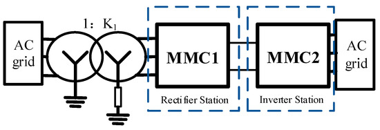
Figure 1.
Structure of back-to-back MMC-HVDC system.
During the open line test (OLT) of an actual back-to-back MMC-HVDC project in China, high-frequency harmonics appeared in system, and after the high-frequency harmonic suppression measures were optimized, other frequency resonance occurrences appeared, showing the continuous high-frequency oscillation phenomenon. Figure 2 shows the AC voltage waveform when the system oscillated for the first time. As shown in Figure 3, the dominant frequency of the harmonic is 1780 Hz and the amplitude is 0.11 pu.
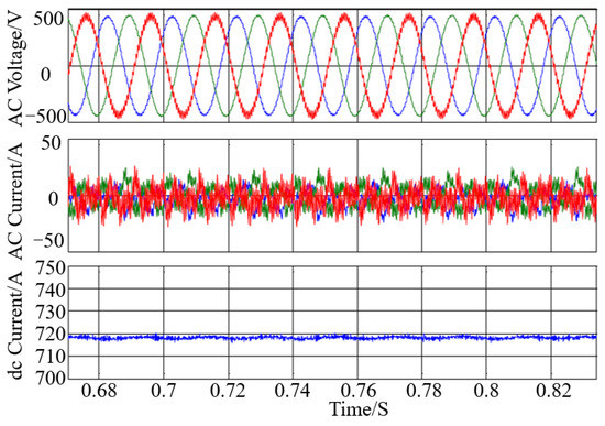
Figure 2.
Waveform of high-frequency oscillation.
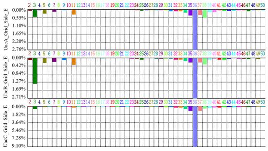
Figure 3.
Spectrum analysis of AC voltage.
After the first high-frequency oscillation, a low-pass filter with a cut-off frequency of 400 Hz is added to the voltage feedforward of the control system to achieve oscillation suppression. However, in the other OLT test, oscillation reappeared in the back-to-back HVDC system and the AC system. The dominant frequency of harmonics was 700 Hz and the amplitude was 0.097 pu as shown in Figure 4.
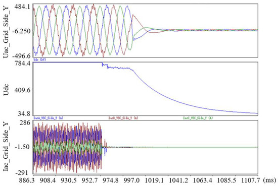
Figure 4.
Waveform of second high-frequency oscillation.
3. High-Frequency Impedance Model of MMC Considering Time Delay
3.1. High-Frequency Small Signal Model of Main Circuit in MMC
The harmonic linearization modeling method is adopted for the high-frequency bands, ignoring the internal dynamics of the MMC, and considering the influence of the power voltage/outer loop, the current inner loop, the phase-locked loop, the arm inductance, and the time delay. The basic idea of harmonic linearization modeling is basically the same as that of the harmonic state space method.
Therefore, the influence of the above factors can be ignored when analyzing the high-frequency oscillation problem. The main circuit model of the MMC is simplified, which is consistent with the two-level converter after simplification. Due to the symmetry of the MMC structure and parameters, the single-phase arm model is taken as an example to calculate the high-frequency impedance model of the MMC main circuit. The current path of the upper arm of the A-phase is shown in Figure 5.
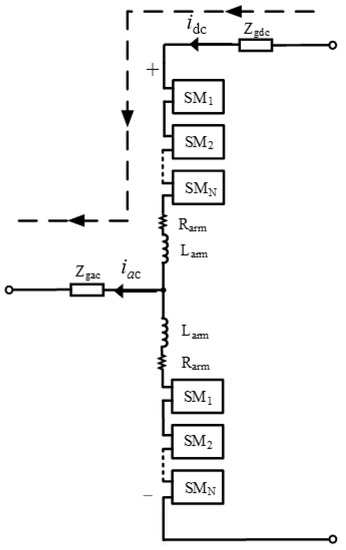
Figure 5.
Equivalent circuit of MMC one phase arm.
According to the equivalent circuit shown in Figure 5, by applying a voltage disturbance to the AC side of the MMC, and further calculating the current disturbance excited by the voltage disturbance, we can obtain:
where Vp is the voltage disturbance injected into the MMC, Is is the corresponding small-signal current response, f1 is the fundamental frequency, and fp is the frequency of the injected disturbance voltage.
3.2. Small Signal Model of MMC Control System Considering Time Delay
Since the control frequency band of the outer loop controller and the phase-locked loop is low, so it can be ignored in modeling. Therefore, the influencing factors considered in MMC high-frequency impedance modeling are power/voltage outer loop, current inner loop, bridge arm inductance, and delay. The simplified control structure block diagram of MMC high-frequency modeling is shown in Figure 6. The specific process of modeling MMC high-frequency impedance based on harmonic linearization is presented.
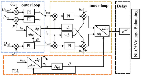
Figure 6.
Simplified control structure of MMC mid-high-frequency modelling.
3.2.1. System Delay Modeling
The actual MMC system contains many time delays, mainly including voltage and current sampling delay, data processing delay, algorithm execution delay, communication delay, etc. It can be seen that the types of delays in the MMC are relatively complex. In this paper, the whole delay is collectively referred to as large time delay, and the large time delay is added between the control system and modulation of the MMC for equivalence, such as Figure 6. The time delay has discrete characteristics and cannot be described by a time domain model. The first-order inertial element can be used to model the control delay.
The first-order or second-order model used in traditional two-level converters can achieve accurate simulation when the delay is less than 200 us and the frequency is less than 1 kHz, but it is difficult to meet the accuracy requirements of a 2 kHz frequency and a large time delay. For this reason, this paper uses the high-order Pade approximation to find the equivalence of the delay, and its specific expression is:
where τ is the delay, l and k are the order of the numerator and denominator polynomials in the Pade approximation, respectively, usually l = k, and the polynomial coefficients of the numerator and denominator can be obtained by Equation (3a,b):
If the Pade approximation order is higher, the accuracy of the equivalent delay in the model is higher, but at the same time it will increase the complexity of the model. The frequency domain characteristics of the fourth-order Pade model are very close to the frequency domain characteristics of the delay in the actual system. In the case of ensuring the complexity and accuracy of the model at the same time, we use the fourth-order Pade approximation to find the equivalence of the time delay.
3.2.2. Power Outer Loop Modeling
According to the control diagram of the power outer loop in Figure 5, the input of the outer loop is the active and reactive power deviation, and the output is the current reference value of the dq-frame current of the inner loop. The expression of the inner loop current reference value can be obtained as:
Bring the three-phase voltage and current into Equation (4) and expand into a Fourier series based on harmonic linearization to obtain the frequency domain expressions of active and reactive power as shown in Equations (5) and (6):
where φi is the phase difference between the AC voltage and AC current, I1 is the amplitude of the three-phase AC current in the steady state, Ip is the current disturbance amount, φip is the phase of the current disturbance, and Ip0 is the current disturbance amplitude.
3.2.3. Current Inner Loop Modeling
The current inner loop control model is shown in Figure 6, and the frequency domain expression of the dq-frame current is obtained as:
In the same way, the frequency domain expression of the three-phase AC voltage after dq transformation is:
Combined with the current inner loop control model, the expression of the output dq-frame reference voltage is obtained as:
where Kd is the current inner loop decoupling coefficient, and GI is the current inner loop open-loop transfer function.
Substitute the power outer loop output, the dq-frame voltage, and the current frequency domain expressions into Equation (10) to obtain the expression of the dq-frame modulation reference voltage as:
Converting the reference voltage from the dq-frame into the abc-frame, and the frequency domain expression of the three-phase reference voltage is obtained as:
where ud0 and uq0 are calculated from the steady-state operating point. In the steady state, there are:
where id0 and iq0 are the dq-frame steady-state currents, respectively.
3.3. High-Frequency Simplified Impedance Modeling of MMC
By combining the frequency domain model of the main circuit of the MMC and the frequency domain model of the control system, the high-frequency simplified impedance modeling of the MMC can be calculated as:
3.4. Impedance Model Verification
In order to verify the accuracy of the high-frequency simplified impedance model in this paper, the impedance frequency sweep test is completed based on the RTDS model of an actual MMC converter station. The specific parameters of the MMC converter station are shown in Table 1. The frequency sweep band is from 300–5000 Hz, and a frequency sweep point is set every 100 Hz. The verification results are shown in Figure 7.

Table 1.
Parameters of MMC.
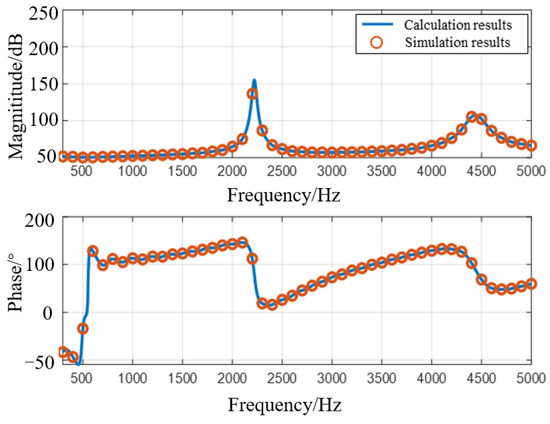
Figure 7.
RTDS verification of MMC high-frequency impedance model.
The RTDS model used in this paper is based on an actual dc project. The dc project adopts the form of conventional UHV DC and flexible UHV DC hybrid transmission, and the sending-end converter station adopts the grid commutated converter (Line Commutated Converter), LCC), the receiving converter station adopts MMC. The receiving-end converter station adopts a true bipolar structure, in which each pole is composed of two converters, and the rated transmission power of a single converter is 1250 MW. The model verified in this paper is based on impedance scan results of the MMC.
“⚪” in Figure 7 is the RTDS frequency sweep result, and the solid line is the analytical calculation result. From the comparison results, it can be seen that the MMC impedance calculation results are basically consistent with the RTDS frequency sweep results. There is a slight error at some frequencies, but the maximum error is within 0.5%, which verifies the accuracy of the high-frequency impedance model built in this paper.
4. Mechanism Analysis of Continuous High-Frequency Oscillation
4.1. Analysis of High-Frequency Oscillation Mechanism of Back-to-Back MMC-HVDC
The inherent delay of the back-to-back MMC-HVDC system will inevitably lead to the existence of poles in the control system, forming an unstable control mode, which may cause oscillation under background harmonic excitation. Pole frequency and inherent delay are reciprocal. In order to control the pole frequency to high-frequency range, the international common practice is to improve software and hardware performance and compress delay time. The impedance characteristics of the back-to-back MMC-HVDC are shown in Figure 8. It can be seen that in the case of feedforward without filtering, the control link has a pole at 1800 Hz, and when the phase angle of the back-to-back MMC-HVDC at the pole exceeds 90°, it is in the negative damping state, and there may be resonance risk under external excitation.
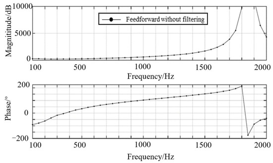
Figure 8.
Impedance characteristics of back-to-back MMC-HVDC.
Sampling and control delay of the back-to-back MMC-HVDC is usually about 550~600 μs, the pole frequency is the inverse of the sampling and control delay and is between 1650 (33 times fundamental frequency) and 1818 Hz (36 times fundamental frequency). Therefore, the high-frequency oscillation will be excited when the background harmonic near 36 times fundamental frequency appears in the AC grid connected with the back-to-back MMC-HVDC. The background harmonics obtained by spectrum analysis of AC power grid are shown in Figure 9.
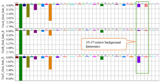
Figure 9.
Background harmonic spectrum analysis.
It can be seen that one of the reasons for the high-frequency oscillation of the back-to-back MMC-HVDC is the existence of ultra-high-frequency background harmonics near the pole frequency in the AC grid. On the other hand, based on the operating control principle of the back-to-back MMC-HVDC system, the disturbance signal will be quickly followed in the ideal state. When the disturbance signal is upper/lower half-wave, the system will adjust downward/upward. The control system will generate a signal opposite to the disturbance to cancel it, which makes the interference signal gradually converge and disappear. In other words, the control system presents a ‘positive damping’ for the interference signal. However, in practical engineering, due to the hardware processing, communication, protocol conversion, and other aspects of the back-to-back MMC-HVDC, it will inevitably delay. When the link delay of the control system is close to the 1/4 or 3/4 period of the high-order harmonics, the upper half wave may be tracked upward and the lower half wave may be tracked downward, forming a continuous oscillation under harmonic disturbance excitation. The schematic diagram of resonance analysis is shown in Figure 10.
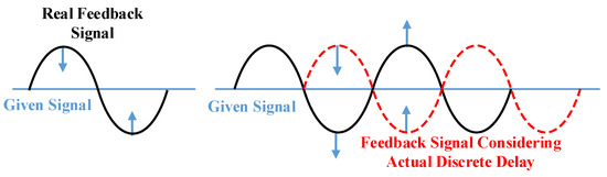
Figure 10.
Qualitative analysis schematic diagram of resonance generation mechanism.
4.2. Mechanism Analysis of Continuous High-Frequency Oscillation Based on Impedance Matching
The impedance equivalent model of the MMC-HVDC and AC system is shown in Figure 11.
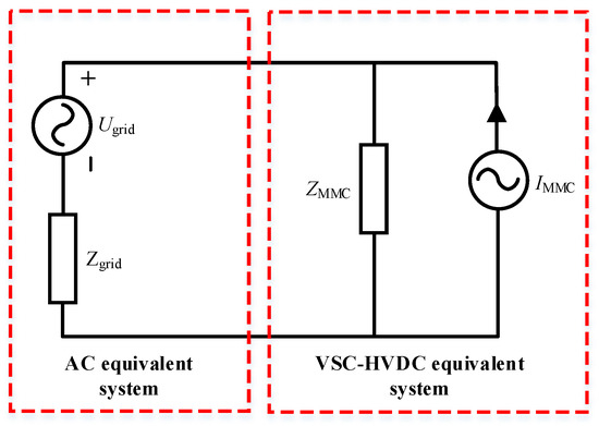
Figure 11.
The equivalent impedance of the MMC-HVDC and AC system.
Where Zgrid is the equivalent impedance of AC system, and Zmmc is the equivalent impedance of VSC-HVDC. According to Nyquist stability criterion:
When the number of Gstability crossing (2k + 1)π from up to down is greater than that crossing (2k + 1)π from down to up in the range of amplitude greater than 0 dB, the interconnected system is unstable. In short, it is considered that the system will resonate when two conditions are satisfied:
- (1)
- The impedance amplitude of MMC-HVDC is consistent with that of the AC system;
- (2)
- The impedance phase angle difference between the MMC-HVDC and AC system is greater than 180°.
Therefore, the dynamic interaction between the control system and harmonic disturbance can be equivalent to the reverse matching of the equivalent impedance model of the back-to-back MMC-HVDC and AC system. When the impedance cannot meet the matching condition, the interconnected system will have high-frequency oscillation under the action of disturbance excitation. In order to cope with this situation, the back-to-back MMC-HVDC usually inputs a low-pass filter with a cut-off frequency of 400 Hz after high-frequency oscillation. The impedance analysis of the interconnected systems with a low-frequency filter is carried out. The results show that the system can suppress the oscillation of more than 1000 Hz after the input of the low-pass filter, but at 685 Hz, the phase difference between the two is 206.43°, that is, there is a new oscillation mode. The impedance characteristics of VSC-HVDC and the AC grid are shown in Figure 12.
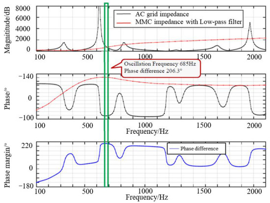
Figure 12.
Impedance characteristic of system with low-pass filter.
Figure 12 shows that, based on the optimized low-pass filter, there will be 14 times fundamental harmonic oscillation in the interconnected system. According to the amplitude–frequency characteristic curve of the filter, it can be seen that 14 times fundamental harmonic cannot be completely filtered out and 30% of the harmonic will remain. The harmonic enters the modulation wave of the back-to-back MMC-HVDC through the feedforward link. In addition, the low-pass filter will cause approximately 0.5 ms delay in the control response of 14 times the fundamental frequency component, which makes the controller unable to track the harmonic effectively. It can be seen that the reason for the continuous high-frequency oscillation of the back-to-back MMC-HVDC is the improper impedance matching between MMC-HVDC and the AC grid near the cut-off frequency of the low-pass filter in the feedforward link.
5. High-Frequency Oscillation Suppression Strategy Based on Nonlinear Low Pass Filter
From the analysis results of the high-frequency continuous oscillation mechanism, the main influencing factor of the high-frequency oscillation of the system is the control link delay, so optimizing the delay link is the best way to suppress high-frequency oscillation. However, for the system in which the delay link cannot be further optimized, additional damping control is needed to improve the negative damping characteristics of MMC-HVDC.
Therefore, in this section, based on the existing additional low-pass or band-stop filter control, an MMC-HVDC high-frequency resonance suppression strategy with nonlinear low-pass filter added to the voltage feedforward link is proposed. This method can better improve the negative damping characteristics of MMC-HVDC in the high-frequency band than the traditional additional low-pass filter control strategy.
5.1. Operation Principle of Nonlinear Low-Pass Filter
For MMC-HVDC based on MMC, the impedance characteristics of MMC can be used to replace the impedance characteristics of MMC-HVDC in the high-frequency band. Adding a low-pass filter to the voltage feed-forward link of the MMC control system can improve the impedance characteristics of MMC in the high-frequency band and block the oscillation frequency component in the grid feed-forward voltage, so as to realize the high-frequency resonance suppression of the interconnected system. The transfer function of the low-pass filter is:
where ξ is the damping coefficient of the low-pass filter and ωn is the center frequency of the filter.
The frequency response curve of the low-pass filter can be obtained from the transfer function of the filter, as shown in Figure 13.
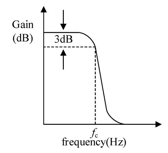
Figure 13.
Filter Frequency response curve of the low-pass filter.
From the frequency response curve of the traditional low-pass filter, it can be seen that the low-pass filter can filter the frequency component above the cut-off frequency. By setting the cut-off frequency of the low-pass filter to less than the high-frequency oscillation frequency in MMC-HVDC, the high-frequency component in the feed-forward voltage of the AC grid can be filtered and the high-frequency resonance suppression can be realized.
The high-frequency problem can be effectively solved by using the low-pass filter. However, due to the inherent characteristics of the quality factor of the low-pass filter, the harmonics near the cut-off frequency cannot be completely filtered, which may lead to the transfer of resonant points. Therefore, special strategy design must be carried out. In this paper, based on the double closed-loop controller, the nonlinear low-pass filter is used for filtering in the inner loop voltage feedforward link. According to the fundamental level of AC voltage, different cut-off frequencies of the low-pass filter is used to further improve the effect of the low-pass filter and avoid the influence of harmonics on the voltage feedforward control. After adding the nonlinear cut-off frequency filter, the simplified control block diagram of MMC is shown in Figure 14:
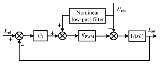
Figure 14.
Simplified control diagram of MMC after adding nonlinear low-pass filter.
Iref represents the reference voltage of the current inner loop, Iout is the AC current, Uabc is the grid voltage, Gi is the PI controller of the current inner loop, KPWM is the modulation coefficient, and 1/(sL) is the simplified model of the main circuit.
5.2. Parameter Design of Nonlinear Low-Pass Filter
According to the transfer function and frequency response characteristics of the low-pass filter, it can be concluded that the main parameters of the low-pass filter design are cut-off frequency ωn and damping coefficient ξ0. The following describes the parameter design process of the nonlinear low-pass filter:
- (1)
- Determination of center frequency and cut-off frequency of the low-pass filter. After the low-pass filter is put into operation, it is still necessary to ensure the flow of the voltage components of fundamental frequency and nearby frequencies, that is, the passband of the low-pass filter is required to contain the fundamental frequency 50 Hz, and the low-pass filter can also block high-frequency oscillation, so the center frequency can be set at 50 Hz, and then the cut-off frequency can be determined according to the selection result of the cut-off frequency screening module ωn.
- (2)
- Initial value of damping coefficient ξ0 of the low-pass filter. The cut-off frequency and center frequency f0 of the low-pass filter jointly define the adjustment range of the low-pass filter. The initial value of the damping coefficient can be calculated according to the cut-off frequency and center frequency of the filter.
- (3)
- Final value of damping coefficient ξn. When the center frequency is given, the greater the damping coefficient, the greater the adjustment degree of the low pass filter to the amplitude and phase characteristics of the impedance, and the larger the corresponding influence range. Therefore, on the basis of the initial value of the damping coefficient, further adjust the damping coefficient according to the requirements of the stability margin of the system and the dynamic adjustment ability of the control link to obtain the final value of the damping coefficient.
The specific resonance suppression process is shown in Figure 15:
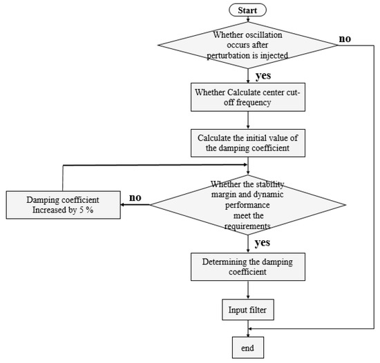
Figure 15.
Resonance suppression process based on additional nonlinear low-pass filter.
5.3. Effect of Nonlinear Low-Pass Filter on Impedance Characteristics of MMC
5.3.1. Analysis of MMC Impedance after Adding Nonlinear Low-Pass Filter
In order to further illustrate the principle of high-frequency oscillation suppression by adding the nonlinear low-pass filter to the voltage feedforward link, the impedance characteristics of MMC before and after adding the nonlinear low-pass filter to the voltage feedforward link are compared, as shown in Figure 16.
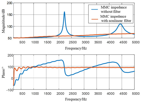
Figure 16.
MMC impedance with/without nonlinear low-pass filter.
From the comparison of the impedance characteristics of the MMC, it can be seen that the nonlinear low-pass filter added to the voltage feed-forward link can effectively improve the impedance characteristics of the MMC in the high-frequency band. The comparison of amplitude–frequency characteristics shows that the resonant peaks of MMC impedance at 2.2 kHz and 4.5 kHz are effectively suppressed. The comparison of phase–frequency characteristics shows that the negative damping phenomenon of the MMC in the high-frequency band is greatly improved, and the stability margin of the system is improved.
5.3.2. Performance Comparison of Different Filters Added to the Feedforward Link
In order to further illustrate the advantages of the additional band-pass filter proposed in this paper, the impedance characteristics of the MMC after adding the nonlinear low-pass filter, a band-stop filter, and a band-pass filter are compared as Figure 17:
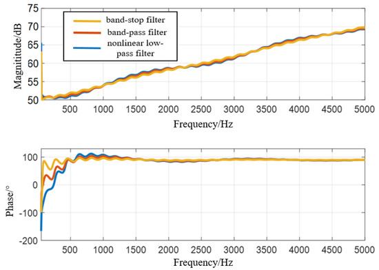
Figure 17.
MMC impedance characteristics using different filters.
Band-pass and band-stop filter transfer functions are described in detail below:
- (1)
- Band-stop filter:
Among ξ is the damping coefficient of the band-stop filter, and f0 is the center frequency of the filter.
- (2)
- Band-pass filter:
Among ξ is the damping coefficient of the band-pass filter, and f0 is the center frequency of the filter.
According to the transfer function of the filter, the frequency response curves of the band-stop filter and the band-pass filter can be obtained, as shown in Figure 18 and Figure 19.
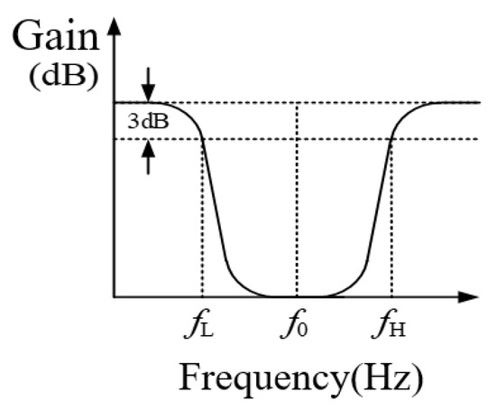
Figure 18.
Filter frequency response curve of band-stop filter.
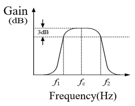
Figure 19.
Filter frequency response curve of band-pass filter.
The parameters of the band-pass filter and band-stop filter are ξ as the damping coefficient and f0 as the center frequency of the filter. Among ξ, the damping coefficient is usually set to 0.707 and f0, the filter center frequency, is usually set to 50 Hz.
As can be seen from Figure 16, the three filters can effectively improve the negative damping phenomenon of the MMC in the high-frequency band, but the performance of the three filters shows obvious differences in the middle frequency band (500~1000 Hz). After the low-pass filter and the band-stop filter, the MMC still has serious negative damping in the mid-frequency band, and the nonlinear low-pass filter can also suppress the negative damping phenomenon in the mid-frequency band well, which shows that the nonlinear low-pass filter can suppress full frequency resonance.
To further illustrate the advantages of the proposed additional nonlinear low-pass filter, the impedance characteristics of the MMC with an additional nonlinear low-pass filter and traditional low-pass filter are compared as follows:
It can be seen from Figure 20 that both filters can effectively improve the negative damping phenomenon of the MMC in the high-frequency band, but the characteristics of the two filters show obvious differences in the frequency band from 500–1000 Hz. After the addition of the traditional band-pass filter, the MMC still has a serious negative damping phenomenon. By using the nonlinear low-pass filter, it can ensure that the phase angle of the interconnected system impedance is not more than 93°, and the phase angle difference of the system impedance is less than 180° in the whole frequency band. There is no impedance resonance matching point, indicating that the nonlinear low-pass filter has better resonance suppression ability than the traditional low-pass filter.
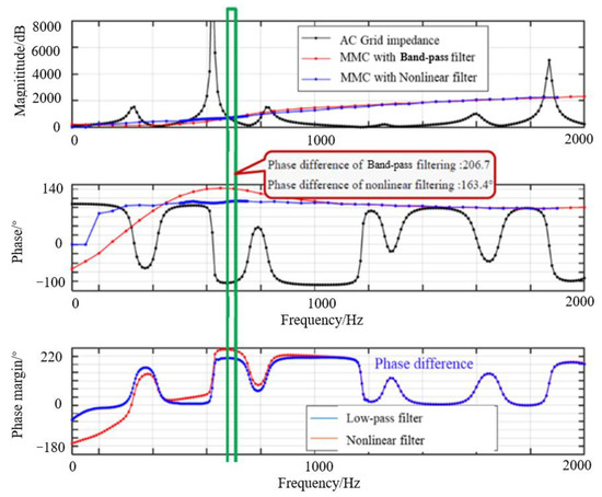
Figure 20.
Stability analysis of MMC using different filters.
It is obvious from Table 2 that the voltage feedforward damping control strategy with the nonlinear low-pass filter has a narrow negative damping band and low control complexity. Although the additional control link can also achieve full frequency resonance suppression, it has a high complexity. Therefore, the additional nonlinear low-pass filter in the voltage feedforward link has a better oscillation suppression effect than the traditional high-frequency oscillation suppression strategy.
Table 2.
Comparison of oscillation suppression ability of different control strategies.
6. Time Domain Simulation Verification
In order to verify the effectiveness of the high-frequency oscillation suppression strategy of the nonlinear low-pass filter, based on the parameters of the MMC converter station in a back-to-back MMC-HVDC project, an MMC-HVDC system is built in MATLAB/Simulink, and the parameters of the system are shown in Table 1. The control system structure of converters are shown in Figure 20.
The simulation results of the high-frequency resonance suppression of the MMC-HVDC system are shown in Figure 20. When t = 1 s, the disturbance source with a frequency of 1.8 kHz is injected into the system, and the voltage amplitude of the disturbance source is 1% of the fundamental voltage amplitude. The system runs stably before the disturbance is injected. After the disturbance is injected, the three-phase voltage and three-phase current at the PCC point show different degrees of high-frequency oscillation. The Nyquist curve of the interconnected system is shown as the blue line in Figure 20. The curve surrounds (−1,j0) points and the system is unstable, which is consistent with the simulation results.
The resonant frequency of the system is determined as high-frequency resonance. The main factor of high-frequency resonance is the delay link. In order to compensate the influence of the delay link, as shown in Figure 21, when t = 1.1 s, the frequency resonance suppression strategy improved in this paper is put into the simulation, which adds the nonlinear low-pass filter to the voltage feedforward link. It can be seen from Figure 20 that the voltage and current of the MMC system gradually returns to stable operation after the filter is put into operation.
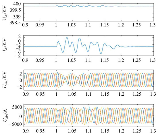
Figure 21.
Simulation verification of low-frequency resonance suppression.
The Nyquist curve of the system is shown as the orange line in Figure 22, and the curve does not surround (−1,j0) points. The system is stable and consistent with the simulation results, which verifies the effectiveness of the proposed oscillation suppression strategy. It should be noted that the main influencing factor of high-frequency resonance is the delay link, and the suppression of high-frequency resonance can also be achieved by directly reducing the control system delay. Therefore, in practical engineering, the high-frequency resonance characteristics of the system can be improved by optimizing the control system delay.
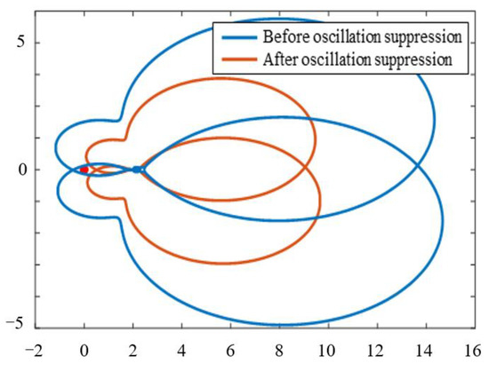
Figure 22.
Nyquist curve before and after low-frequency resonance suppression.
7. Conclusions
This paper takes the MMC-HVDC system as the research object, establishes the impedance model of the MMC, and proposes a high-frequency oscillation suppression strategy based on a nonlinear filter. In the three-phase balanced system, the simplified high-frequency impedance model can accurately describe the MMC impedance characteristics, which can be applied to the high-frequency oscillation study of the MMC-HVDC system.
The reason for the continuous high-frequency oscillation of the MMC-HVDC system is that the impedance of the MMC-HVDC system and the AC grid does not match after the low-pass filter is put into the MMC. The high-frequency oscillation suppression strategy proposed in this paper can optimize the impedance characteristics of the MMC-HVDC system in all frequency bands, which greatly reduces the risk of high-frequency oscillation of the system.
Author Contributions
Conceptualization, H.W., N.Z., P.H. and X.D.; methodology, H.W.; software, H.W.; validation, P.H. and X.D.; formal analysis, R.H.; investigation, X.D.; resources, P.H.; data curation, H.W.; writing—original draft preparation, P.H.; writing—review and editing, X.D.; visualization, R.H.; supervision, R.H.; project administration, P.H. and X.D.; funding acquisition, R.H. All authors have read and agreed to the published version of the manuscript.
Funding
This research received no external funding.
Data Availability Statement
Data is contained within the article.
Conflicts of Interest
The authors declare no conflict of interest. The funders had no role in the design of the study; in the collection, analyses, or interpretation of data; in the writing of the manuscript, or in the decision to publish the results.
References
- Zhou, B.R.; Hong, C.; Jin, X.M. Study of Backbone Structure Change from Synchronous to Asynchronous in China Southern Power Grid. Proc. CSEE 2016, 36, 2085–2092. [Google Scholar]
- Li, Y.; Tang, G.; Ge, J.; He, Z.; Pang, H.; Yang, J.; Wu, Y. Modelling and damping control of modular multilevel converter based DC grid. IEEE Trans. Power Syst. 2018, 33, 723–735. [Google Scholar] [CrossRef]
- Wan, X.; Li, Y.; Peng, M. Modelling, analysis and virtual parallel resistor damping control of VSC-based DC grid using master–slave control mode. IET Gener. Transmiss. Distrib. 2018, 12, 2046–2054. [Google Scholar] [CrossRef]
- Zou, C.; Rao, H.; Xu, S.; Li, Y.; Li, W.; Chen, J.; Zhao, X.; Yang, Y.; Lei, B. Analysis of resonance between a VSC-HVDC converter and the AC grid. IEEE Trans. Power Electron. 2018, 33, 10157–11016. [Google Scholar] [CrossRef]
- Saad, H.; Fillion, Y.; Deschanvres, S.; Vernay, Y.; Dennetiere, S. On resonances and harmonics in HVDC-MMC station connected to AC grid. IEEE Trans. Power Deliv. 2017, 32, 1565–1573. [Google Scholar] [CrossRef]
- Liu, H.; Sun, J. Voltage stability and control of offshore wind farms with ac collection and HVDC transmission. IEEE J. Emerg. Sel. Top. Power Electron. 2014, 2, 1181–1189. [Google Scholar]
- Cheah-Mane, M.; Sainz, L.; Liang, J.; Jenkins, N.; Ugalde-Loo, C.E. Criterion for the Electrical Resonance Stability of Offshore Wind Power Plants Connected Through HVDC Links. IEEE Trans. Power Syst. 2017, 32, 4579–4589. [Google Scholar] [CrossRef]
- Amin, M.; Rygg, A.; Molinas, M. Self-Synchronization of Wind Farm in an MMC-Based HVDC System: A Stability Investigation. IEEE Trans. Energy Convers. 2017, 32, 458–470. [Google Scholar] [CrossRef]
- Ji, K.; Liu, S.; Pang, H.; Yang, J.; Xu, Z.; He, Z.; Tang, G. Generalized Impedance Analysis and New Sight at Damping Controls for Wind Farm Connected MMC–HVdc. IEEE J. Emerg. Sel. Top. Power Electron. 2021, 9, 7278–7295. [Google Scholar] [CrossRef]
- Sun, J.; Liu, H. Sequence impedance modeling of modular multilevel converters. IEEE J. Emerg. Sel. Top. Power Electron. 2017, 5, 1427–1443. [Google Scholar] [CrossRef]
- Zhou, J.Z.; Ding, H.; Fan, S. Impact of short-circuit ratio and phase-locked loop parameters on the small-signal behavior of a VSC-HVDC Converter. IEEE Trans. Power Deliv. 2014, 29, 2287–2296. [Google Scholar] [CrossRef]
- Wang, Y.; Wang, X.; Blaabjerg, F.; Chen, Z. Harmonic instability assessment using state space modeling and participation analysis in inverter-fed power systems. IEEE Trans. Ind. Electron. 2017, 64, 806–816. [Google Scholar] [CrossRef]
- Wang, C.; Xiao, L.; Jiang, H.; Cai, T. Analysis and compensation of the system time delay in an MMC system. IEEE Trans. Power Electron. 2018, 33, 9923–9936. [Google Scholar] [CrossRef]
- Wu, H.; Wang, X.; Kocewiak, Ł.; Harnefors, L. AC impedance modeling of modular multilevel converters and two-level voltage-source converters: Similarities and differences. In Proceedings of the IEEE 19th Workshop Control Modeling for Power Electronics, Padua, Italy, 25–28 June 2018; pp. 1–8. [Google Scholar]
- Zhu, J.; Hu, J.; Lin, L.; Wang, Y.; Wei, C. High-Frequency oscillation mechanism analysis and suppression method of VSC-HVDC. IEEE Trans. Power Electron. 2020, 35, 8892–8896. [Google Scholar] [CrossRef]
- Cespedes, M.; Sun, J. Adaptive control of grid-connected inverters based on online grid impedance measurements. IEEE Trans. Sustain. Energy 2014, 5, 516–523. [Google Scholar] [CrossRef]
- Harnefors, L.; Bongiorno, M.; Lundberg, S. Input-Admittance calculation and shaping for controlled voltage-source converters. IEEE Trans. Ind. Electron. 2008, 54, 3323–3334. [Google Scholar] [CrossRef]
- Lyu, J.; Cai, X.; Molinas, M. Optimal design of controller parameters for improving the stability of mmc-hvdc for wind farm integration. IEEE J. Emerg. Sel. Top. Power Electron. 2017, 6, 40–53. [Google Scholar] [CrossRef]
- Dannehl, J.; Liserre, M.; Fuchs, F.W. Filter-based active damping of voltage source converters with lcl filter. IEEE Trans. Ind. Electron. 2011, 58, 3623–3633. [Google Scholar] [CrossRef]
- Wang, X.; Blaabjerg, F.; Loh, P.C. Grid-current-feedback active damping for lcl resonance in grid-connected voltage-source converters. IEEE Trans. Power Electron. 2016, 31, 213–223. [Google Scholar] [CrossRef]
- Guo, X.; Liu, Z.; Li, Y.; Lu, Y. Characteristic analysis of high-frequency resonance of flexible high voltage direct current and research on its damping control strategy. Proc. CSEE 2020, 40, 19–29+370. (In Chinese) [Google Scholar]
- Du Dongye, G.C.; Xiufang, J. Suppression strategy for high-frequency resonance ofmodular multilevel converter based on additional band-stop filter. Trans. China Electrotech. Soc. 2021, 36, 1516–1525. (In Chinese) [Google Scholar]
- Li, Y.; An, T.; Zhang, D.; Pei, X.; Ji, K.; Tang, G. Analysis and Suppression Control of High-frequency Resonance for MMC-HVDC System. IEEE Trans. Power Deliv. 2021, 36, 3867–3881. [Google Scholar] [CrossRef]


Publisher’s Note: MDPI stays neutral with regard to jurisdictional claims in published maps and institutional affiliations. |
© 2022 by the authors. Licensee MDPI, Basel, Switzerland. This article is an open access article distributed under the terms and conditions of the Creative Commons Attribution (CC BY) license (https://creativecommons.org/licenses/by/4.0/).