Article

Multi-Gbps LDPC Decoder on GPU Devices

1
Engineering Research Center of Digital Audio and Video, Communication University of China, Beijing 100024, China
2
State Key Laboratory of Media Convergence and Communication, Communication University of China, Beijing 100024, China
*
Author to whom correspondence should be addressed.
Electronics 2022, 11(21), 3447; https://doi.org/10.3390/electronics11213447
Submission received: 24 September 2022 / Revised: 18 October 2022 / Accepted: 22 October 2022 / Published: 25 October 2022

Abstract

:
To meet the high throughput requirement of communication systems, the design of high-throughput low-density parity-check (LDPC) decoders has attracted significant attention. This paper proposes a high-throughput GPU-based LDPC decoder, aiming at the large-scale data process scenario, which optimizes the decoder from the perspectives of the decoding parallelism and data scheduling strategy, respectively. For decoding parallelism, the intra-codeword parallelism is fully exploited by combining the characteristics of the flooding-based decoding algorithm and GPU programming model, and the inter-codeword parallelism is improved using the single-instruction multiple-data (SIMD) instructions. For the data scheduling strategy, the utilization of off-chip memory is optimized to satisfy the demands of large-scale data processing. The experimental results demonstrate that the decoder achieves 10 Gbps throughput by incorporating the early termination mechanism on general-purpose GPU (GPGPU) devices and can also achieve a high-throughput and high-power-efficiency performance on low-power embedded GPU (EGPU) devices. Compared with the state-of-the-art work, the proposed decoder had a ×1.787 normalized throughput speedup at the same error correcting performance.

Graphical Abstract

1. Introduction

Low-density parity-check (LDPC) codes, proposed by Gallager in 1962 [1] and rediscovered by Mackay and Neal in 1996 [2], are a class of error-correction codes whose performance is close to the Shannon limit. They have been used in many communication systems, such as 5G New-Radio (NR) [3], WiMAX (802.16e) [4], WiFi (802.11N) [5], and DVB-S2 [6]. Moreover, the LDPC code was also used in the CV-QKD system [7] and the NAND memory storage [8]. However, LDPC codes also have the disadvantage of a high decoding complexity, which becomes a significant challenge to meet the requirements for high throughput in communication systems. For example, the peak throughput of the 5G NR standard needs to achieve 10 Gbps [9]. Therefore, the design of high-throughput LDPC decoders has attracted significant attention.
Due to the high parallelism of LDPC decoding algorithms, high-throughput LDPC decoders can be achieved by devices with parallel processing capabilities. Based on specialized hardware platforms such as ASIC and FPGA, the decoding throughput performance of LDPC decoders can be extremely high [10,11,12,13] but also bring a high development cost. Different from traditional development methods, soft-defined radio (SDR) technology offers a software-based solution for many hardware devices in communication systems [14,15]. This software solution considerably reduces the hardware resources and development time necessary for the deployment of radio-based communications systems, and it can be very useful when testing protocols, prototypes, and applications in a simple and economical way. However, traditional SDR implementation platforms, such as X86 CPU, have limited hardware resources and cannot meet the high throughput requirements of communication systems. Due to the advantage of graphics processing unit (GPU) devices offering a large number of computing cores, decoders based on GPU can also achieve a high throughput and even outperform FPGAs in some cases [16]. GPU also has the advantage of configurable flexibility, as the compute unified device architecture (CUDA) from NVIDIA Corporation enables efficient software design of GPU devices [17]. It should be noted that GPUs from other manufacturers can implement the software design by the OpenCL protocol [18]. In addition, for the application of GPU in an embedded platform, many researchers have also studied the computation optimization technology of embedded GPU (EGPU) and achieved good results [19,20]. Due to these advantages, GPU plays an important role in communication systems based on SDR platforms. As a result, the designs of the high-throughput GPU-based decoder that can be dynamically configured to enable multi-length and multi-rate decoding have become increasingly more attractive.
GPU-based high-throughput LDPC decoders have been widely studied in the past years [21,22,23,24,25,26]. In [21], a high-throughput decoder based on layered scheduling was proposed. Some GPU-based optimizations were presented in [22] to obtain a high throughput, which reached a 1.27 Gbps peak throughput on a single GPU. By applying an optimized message updating scheme for QC-LDPC of 5G NR, two GPU-based LDPC decoders based on flooding and layered scheduling were presented in [23], respectively. The shortening and puncturing techniques in 5G NR were adopted in [24] when designing the LDPC decoder. To meet the different demands of 5G NR, [25] proposed an LDPC decoder with various working modes. The authors of [26] proposed a low-latency decoder design strategy that exploits additional parallelism, which also has a high throughput performance. However, despite the availability of many GPU-based LDPC decoders, a decoder designed for scenarios that can handle large-scale data is still lacking.
To address the challenge of the scenario required to process a large amount of data, this paper proposes a novel high-throughput flooding-based LDPC decoder, which can handle different rates and lengths of LDPC codes. To maximize the utilization of the parallel processing ability of GPU, the decoding parallelism of the decoder is optimized from intra-codeword and inter-codeword parallelisms, respectively. According to the characteristics of flooding scheduling, the intra-codeword parallelism is improved by reasonably configuring CUDA kernels. The inter-codeword parallelism is greatly increased by utilizing the SIMD instruction. To meet the demands of processing of large-scale data, we optimize the data scheduling strategy by reasonably allocating the memory during decoding. The experiment results show that the proposed decoder can reach 10 Gbps with the early termination (ET) mechanism on general-purpose GPU (GPGPU) devices. The proposed decoder can also obtain a high-throughput and high-power-efficiency performance on the EGPU devices. Compared with the state-of-the-art work [26], it has a normalized throughput with a ×1.787 speedup. In short, the main contributions of this paper can be summarized as follows:
(1)
We propose a high decoding parallelism GPU-based LDPC design scheme, which further optimizes intra-codeword and inter-codeword parallelisms to improve the throughput performance.
(2)
We propose a new GPU-based data scheduling strategy, which enhances the off-chip memory utilization to match well with different rates and lengths of LDPC codes and meet the requirements of large-scale data processes.
(3)
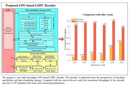
Combined with the high decoding parallel design scheme and data scheduling strategy, we implement GPU-based high-throughput decoders on GGPU and EGPU devices, respectively. The experimental results show that the proposed decoder outperforms the state-of-the-art work in scenarios that need to process large-scale data.
The remainder of this paper is structured as follows. In Section 2, the characteristics of LDPC codes and the decoding algorithms are briefly introduced. Section 3 illustrates the implementation of the proposed GPU-based LDPC decoder in detail. The performance test results and analysis of the decoder and comparisons with other implementations are given in Section 4. Section 5 discusses the future improvement direction of our decoder. The conclusions are found in Section 6.

2. LDPC Codes and Decoding Algorithms

LDPC codes are a class of linear ( N , K ) block codes defined by an M × N sparse binary parity-check matrix (PCM) H , with K = N M and r a t e = K / N . PCM H can be used to create a bipartite Tanner graph, where rows correspond to check nodes (CNs), columns correspond to variable nodes (VNs), and non-zero elements in the H represent the edge linking CNs and VNs [27]. LDPC codes can be decoded by using the belief propagation (BP) method. The central theory of most LDPC decoding algorithms is that any incorrect bits may be found and corrected by sending messages from VNs to CNs. Therefore, LDPC decoding algorithms must iteratively compute the message passing between VNs and CNs to obtain the decoded data [28].
The two major decoding algorithms of LDPC are the Sum-Product algorithm (SPA) and the Min-Sum algorithm (MSA). Through these decoding algorithms, a posteriori probabilities (APPs) can are obtained [29]. As a typical simplification algorithm of SPA, MSA decreases the computational complexity of the CN computation in SPA, but the simplicity reduces the error correcting performance [30]. To overcome this issue, two MSAs, normalized MSA (NMSA) [31] and offset MSA (OMSA) [32], with a scaling parameter or an offset are presented to address this issue. NMSA and OMSA optimize MSA to provide negligible error correction performance loss while ensuring low algorithm complexity. The authors of [33] found that the decoding latency of OMSA is 10% faster than NMSA.
Flooding, layered, and shuffled are three commonly used scheduling for LDPC decoding algorithms [23]. Flooding scheduling divides the decoding algorithm into two independent phases: CN computation and VN computation. In the CN computation phase, all the check-to-variable (C2V) messages are updated, and in the VN computation phase, the variable-to-check (V2C) messages are updated. Layered and shuffled scheduling group the decoding computations according to the row and column of PCM, respectively [34,35]. Taking layered scheduling as an example, the computations of CN and its linked VNs are performed together. Compared with flooding scheduling, layered and shuffled scheduling achieve the same decoding performance with only half the number of iterations, thus reducing the decoding delay (layered scheduling is less complex than shuffled scheduling [36]). However, despite layered and shuffled scheduling reducing the decoding latency, the reduction of iteration number results in the data dependence of CN and VN computations, which means the computation cannot be fully paralleled. As a result, layered and shuffled scheduling have much lower parallelism than flooding scheduling [37].
Based on the above analysis, we adopt the flooding-based OMSA to maximize the decoding parallelism of the GPU-based LDPC decoder. The specific decoding steps of the flooding-based OMSA are shown as follows:
In the first step, the initialization of the algorithm starts. The initial messages sent to each VN are configured using the corresponding initial log-likelihood ratio (LLR) data. The expression of the initial message for each VN is stated as:
V n m 0 = L n LLR .
The second step is the CN computation, where C2V messages from CNs to VNs are computed. The formula for updating the C2V messages is expressed as:
s i g n C 2 V = n s i g n ( V n m i 1 ) , n [ 0 , N 1 ] \ m ,
C m n i = { m i n ( m i n 1 β , 0 ) × s i g n C 2 V , m i n 1 V n m ( n = m ) i 1 m i n ( m i n 2 β , 0 ) × s i g n C 2 V , e l s e .
The third step is the VN computation, where V2C messages from VNs to CNs are computed. The formula for updating the V2C messages is expressed as:
V n m i = L n LLR + m C m n i , m [ 0 , M 1 ] \ n .
After performing the maximum number of iterations, the final hard decision operation can be taken as indicated in the fourth step. The formula for the hard decision is expressed as:
L n A P P = V n m i + C m n ( m = n ) i ,
D n = { 0   , L n A P P 0 1   , L n A P P > 0 .
The meanings of the variables in four steps are shown as follows: m and n stand for the indexes of the check and variable nodes and the range of values is [ 0 ,   M 1 ] and [ 0 ,   N 1 ] , respectively. i represents the current number of iterations. C m n i and V n m i are the C2V messages from the m th CN to the n th VN and V2C messages from the n th VN to the m th CN at the i th iteration, respectively. s i g n C 2 V is the sign bit of the C2V message. m i n 1 and m i n 2 are the minimum and sub-minimum values in the V2C messages of all the VNs linked to one CN. β that appeared in the updates of the C2V messages is the offset factor. L n LLR stands for the LLR data to be decoded. L n A P P stands for the APP data obtained by the decoding iterations. D n represents the binary decoded data obtained after the hard decision.

3. Proposed High-Throughput GPU-Based LDPC Decoder

The utilization of the parallel processing capability of GPU and the data scheduling strategy are two crucial factors for a high-throughput GPU decoder. To fully utilize the parallel processing capabilities of GPU, we propose a high decoding parallelism design scheme. The decoding parallelism can be improved by extending the intra-codeword parallelism or increasing the number of codewords decoding in parallel (the inter-codeword parallelism). To improve the intra-codeword parallelism, the design uses the characteristics of flooding scheduling to configure the CUDA kernels reasonably. To improve the inter-codeword parallelism, the design uses the SIMD instructions to increase the number of codewords decoding in parallel. For a higher throughput when decoding large-scale data, the targeted optimization for the data scheduling strategy is made. We reasonably allocate the GPU memory to improve the memory access efficiency and utilize many methods to reduce the data transmission delay.
The proposed decoder is based on the CUDA platform and follows the selected algorithm in Section 2. To describe the proposed decoder more clearly, the (8448, 26,112) LDPC code in 5G NR is set as an example for the below descriptions.

3.1. High Decoding Parallelism Design Scheme

To improve the intra-codeword parallelism, the design must be effectively mapping the decoding algorithm to GPU devices. In our design, we extend the architecture described in [25] and divide the decoding progress into six parts: (1) Initialization and ordering, (2) check node update, (3) variable node update, (4) hard decision, (5) evaluate check (optional), and (6) bit packed and reordering. Each part corresponds to one CUDA kernel (in CUDA terminology, a kernel denotes an enclosed function). Compared with [25], the introduction of initialization and ordering and hard decision parts further exploits the parallelizable computation in the flooding scheduling algorithm, which efficiently improves the intra-codeword parallelism. In addition, considering the iteration number under high signal-to-noise ratio (SNR) regions is few, we introduce the evaluate check part, which can judge whether the decoding process should be terminated early, thereby reducing the launch number of decoding kernels. The processing flow chart of the design is shown in Figure 1 and Figure 2.
To improve the inter-codeword parallelism, the SIMD instruction of GPU is utilized in this design. Due to the data type for the SIMD instruction built into CUDA being 32-bit, two 16-bit or four 8-bit data can be processed simultaneously. Motivated by [33], we take advantage of the SIMD instructions at the codeword level, which can execute the same computation sequence (the flooding-based OMSA) over different codewords. Since the LDPC decoding algorithm is not sensitive to quantization [38], each message element during decoding can be represented by 8-bit data in this design. As a result, the addition of SIMD instructions can quadruple the number of simultaneously processed codewords and further extends the inter-codeword parallelism.
Although the utilization of the SIMD instructions improves the inter-codeword parallelism, additional preparation works are needed. When utilizing the SIMD instruction, four 8-bit elements with an identical location from four codewords must be packed into one 32-bit data before decoding, and the 32-bit data should be unpacked into four 8-bit data after the hard decision. It should be noted that the pack and unpack operations in this design are called ordering and reordering, respectively. To reduce the ordering and reordering time, these operations are implemented on GPU to allow parallel execution of the reordering and ordering procedures. The ordering operation is incorporated into the initialization and ordering kernel for the proposed decoder. The reordering operation is performed in the bit packed and reordering kernel before the decoded data is transmitted to the CPU memory. Note that these operations involve data synchronization, which results in an extra overhead. However, this impact is limited due to the following two reasons: (1) We utilize the advantages of the GPU parallel process and save a lot of time compared with performing these operations on CPU; (2) since ordering and reordering operations are performed only once per decoding, the operation time without change in the number of iterations is negligible compared to the total time. The diagram of the ordering and reordering procedures is shown in Figure 3.
The details of the CUDA kernel implementation for the decoder are described in the next section.

3.1.1. Initialization and Ordering

This kernel is mainly responsible for the initialization and ordering works. Before the iteration decoding begins, the initial value V n m 0 of the V2C messages must be initialized by the LLR data L n LLR . Since L n LLR from various codewords is not aligned in the GPU memory, the message V n m 0 must be ordered in accordance with the index of the associated position in H to use the SIMD instruction.
For the initialization and ordering of four codewords, the total number of threads in this kernel is N , where N stands for the column number of H . The single thread in this kernel corresponds to a single VN. Through bit operations, the messages V n m 0 at the same location of four codewords are packed by each thread.

3.1.2. Check Node Update

Each thread in the check node update kernel corresponds to one CN, and the C2V messages C m n of the relevant check node in the Tanner graph are computed in this kernel. Since the CN computation of MSA can be reduced to multiplication and addition, searching for the minimum and sign computations are performed separately. Two loops in this kernel each perform one of these computations, respectively. In the first loop, the minimum value m i n 1 and subminimum value m i n 2 in all absolute values of the messages V n m are found using the vmin and vabs instructions to scan all VNs linked to the corresponding CN, and the total product of the sign values is also computed. In the second loop, the absolute values of the current message C m n are selected from m i n 1 and m i n 2 by the vcmpene and vcmpeq instructions, and the sign bit is obtained by multiplying the sign value of the current V2C message and the total product of the sign values obtained from the first loop. The implementation of the check node update process in this kernel is shown in Figure 4.

3.1.3. Variable Node Update

The implementation of this kernel follows the updated principle of one thread for one VN. This kernel includes two loops. By calculating the sum of the message V n m and message C m n of the connected edge, the first loop updates the APP data L n A P P (the vaddss instruction is used). Utilizing the APP data L n A P P to subtract the C2V message of the linked one (the vsubss instruction is used), the second loop can yield the message V n m of each VN. The implementation of the variable node update process in this kernel is shown in Figure 5.

3.1.4. Hard Decision

The design of the hard decision kernel also follows the principle of one thread for one variable node update. When performing the hard decision, the vmaxs instruction is used. If the corresponding data L n A P P is positive, the decoded data is 1; otherwise; it is 0.

3.1.5. Evaluate Check

In order to improve the decoding speed of the decoder, this design introduces the ET mechanism, which can effectively reduce the number of decoding iterations in the case of a high SNR, thereby reducing the time required for decoding. It should be noted that the evaluate check part is optional and can be closed by the ET_flag in the GPU program. The difference between closing and opening this kernel can be found in Figure 1 and Figure 2.
The formula for the ET mechanism to decide whether the decoding iteration can be terminated is as follows:
D n × H T = 0 .
The evaluation check will be satisfied if all the results of the sum are zero. Then, the decoding iteration can be terminated. To reduce the check time, this parallelized kernel implements the sum operation of decoded data in the same row of H , and the thread of this kernel follows one thread for one row. The implementation of the check process in this kernel is shown in Figure 6. It should be noted that the iteration will only stop when the data of the four code blocks meet the requirements of the formula at the same time due to the addition of the SIMD instruction.

3.1.6. Bit Packed and Reordering

This kernel is mainly responsible for the decoded data ordering and packing works. Corresponding to the ordering operation, the reordering operation is performed in this kernel. To reduce the transmission latency, we implement the bit packed operation in this kernel to pack the decoded data. The process of the bit packed and reordering kernel is shown in Figure 7. Each thread in this kernel first performs the ordering operation, unpacking 32-bit data to four 8-bit data. Then, the thread grabs eight adjacent 8-bit from the decoded data pack to one 8-bit data because the decoded data can be represented by one bit after the hard decision. In addition, only the information data (length is K ) in the decoded data (length is N ) is useful after the decoding iteration, so the length of the final data that needs to be transferred becomes K / 8 . As a result, the amount of data transferred from the GPU device memory back to the CPU host memory is reduced after the bit is packed, and the transfer time becomes 1/32 of the 32-bit quantization scheme.

3.2. Data Scheduling Strategy

For a high throughput performance, an appropriate data scheduling strategy is crucial when designing a GPU-based decoder. The data scheduling strategy mainly includes two parts: memory allocation and data transmission. For the scenario that needs to process large-scale data, we propose a reasonable memory allocation strategy during decoding according to the features of the selected LDPC decoding algorithm and GPU memory, which enhance the utilization of the off-chip memory. In addition, the proposed decoder compresses PCM to reduce the storage space. To improve the transmission efficiency, we utilize many optimized methods to reduce the transmission time between GPU and CPU. The details of the data scheduling strategy are described in the next section.

3.2.1. Memory Allocation Strategy during Decoding

To design a suitable memory allocation strategy, we study the characteristics of different GPU memories in depth. The GPU memory can be divided into two categories: on-chip memory and off-chip memory. The size of the on-chip memory is smaller than the off-chip memory but has a faster read-write speed. Registers and shared memory are both on-chip memory. Different from the coverage of the register being one thread, the shared memory can be used in the threads of one block. Registers have a faster read-write speed than shared memory. Constant memory and global memory are off-chip memory. Constant memory is a read-only memory on the board, and the reading speed is faster than global memory. Based on the above analysis, the memory allocation of the proposed decoder is illustrated in Figure 8 (the solid line represents the data transfer between GPU and CPU, and the dotted line represents the data flow in the GPU device), and the details are described as follows:
In most CUDA kernels of the decoding loop, the C2V message C m n and V2C message V n m that are passed between variable nodes and check nodes, in addition to the APP data L n A P P , are accessed very frequently. Therefore, they are the most crucial pieces of data during decoding iteration. However, the proposed decoder should support LDPC codes of different lengths and rates, which increases the possibility that the quantity of memory needed for message data will exceed the capacity of on-chip memory. Due to the various row degrees in PCM, the global memory is the only practical choice remaining for addressing the requirement for quasi-random access to the message data. Therefore, these data are stored in the global memory. In addition, in order to improve the utilization of the memory space, L n A P P data reuse the storage space of the message V n m during decoding iteration.
The LLR data L n LLR and APP_bit data are stored in the global memory. Although the L n LLR data is read-only during initialization, L n LLR data is stored in the global memory instead of the constant memory considering the large amount. Due to neighboring elements of L n LLR data being accessed by adjacent threads, these accesses are merged to obtain high memory access efficiency. When the hard decision kernel is executed, L n LLR data is reused to store the decoded data obtained after the decision. The APP_bit data is the final decoded data that needs to be copied to the host memory, and it is obtained by the bit-packed operation.
s i g n c 2 v , m i n 1 , m i n 2 , and s u m are temporary variables generated in node computations. In the proposed decoder, node computations correspond to the check node update kernel and variable node update kernel; thus, these temporary variables are stored in the registers of the corresponding thread.
When performing the ordering operation, the amount of data that must be ordered is too large compared with the capacity of the on-chip memory; thus, the ordering operation is performed on the global memory. Since we use the bit packed operation to compress the decoded data, the size of the reordering data is just K / ( N * 8 ) of ordering. Therefore, the shared memory can be used to reduce the reordering time. However, as the size of the reordering data increases with the codeword number, the shared memory cannot meet the storage demand when decoding a large number of codewords. Consequently, we need to change the storage method to meet the demands of different codeword numbers.
We adopt an adaptive strategy, which can efficiently utilize memory resources to improve the memory access efficiency during reordering. According to the shared memory size of GPU devices, we can precompute the max codeword number, which can use shared memory. Then, the storage method can be selected by comparing the current codeword number with the max codeword number. For example, the shared memory size of RTX 2080Ti is 49.15 kb. If decoding the LDPC code (8448, 25,344), the max codeword number that can execute the reordering operation in the shared memory is 4 (since the decoder uses the SIMD instructions, the number of codewords is a multiple of 4), and we need to use the global memory when the codeword number is larger than 4.
To avoid random memory access, when designing the kernel of the ordering and reordering operation in Section 3.1, we ensure that the data accessed by adjacent threads is adjacent to the memory address. Therefore, even if the global memory is being used, our decoder also can allow the coalesced memory access in the same swap to improve the memory access efficiency when performing the ordering and reordering operations.

3.2.2. Storage Method for PCM

Since PCM H is not changed during decoding iteration and needs to be used by most kernels, we can store H in the constant memory to reduce the memory access latency. However, due to the limited size of the constant memory, we should compress H before decoding. Since the ‘0’ elements in H do not participate in the decoding iteration, these elements can be ignored. Based on the compressed column storage (CCS) method [39], we order and compress H to the row-degree and column-degree versions for the VN update and CN update computations, respectively. For the row-degree version, we need to count the number of non-‘0’ elements (row degree) in each row, and then order the row of H according to the row degree. After ordering, we only need to store the row degree and non-0 element index of each row. Similarly, for the column-degree version, we only need to store the column degree and non-0 element index of each column. The ordering operation in the compress method is to meet the requirement of CUDA for the fixed-sized data structure, thereby avoiding accessing erroneous places while decoding. It should be noted that when the matrix is too large, the data index will be beyond the range of 8-bit data, so we use the 16-bit data type to store the compressed matrix information. After compression, the row-degree version and column-degree version matrix are loaded by the host onto the constant memory of GPU, and the storage space occupied by H with a code rate of 1/3 in 5G NR becomes 0.03% of the original. The details of the compression method are shown in Figure 9.

3.2.3. Data Transfer Strategy

When processing large-scale data, the transmission delay between GPU and CPU hinders the improvement of the throughput performance. To reduce the transmission delay, we use three methods. First, the CPU side uses pinned memory (API cudaHostAlloc()) to store data, which can improve the efficiency of the addressing operations. Second, the data during decoding are represented by the 8-bit char unit without an error-correction performance loss and the decoded data are represented by 1-bit after the hard decision, then the data transfer time can be significantly reduced compared with the 32-bit float data. Third, the transfer time can be overlapped with the kernel execution by the asynchronous data transfer mode that CUDA-enabled GPUs provide. Since the streams are independent of each other and can be executed in parallel, we design a multiple-stream mode to decode different codewords. The multiple-stream mode contributes to ensuring the computational resources are fully utilized most of the time and reduces the waiting time for new data.

4. Experimental Results and Analysis

In this section, we test and analyze the performance of the proposed GPU-based LDPC decoder. The performances of the proposed decoder are tested over an additive white Gaussian noise (AWGN) channel and modulated by binary phase-shift keying (BPSK). The scale factor β of OMSA is 1. The experimental results are averaged over 100,000 times.
The experiments of the GPGPU device are conducted on GeForce RTX 2080Ti. RTX 2080Ti is Turing architecture, with 4352 CUDA cores and 11GB of GDDR6 memory. The software program of the proposed decoder is developed with C language and complied by GCC11.1 and CUDA11.3. The CPU type of the host platform is Intel i9-9900K, and the GNU/Linux 5.12.15-arch1-1 (X86_64) is used as the operating system.

4.1. Throughput and Latency Performance Analysis

In Figure 10, the decoding throughput and latency of the decoder processing various numbers of codewords based on GPGPU are shown. The throughput performance for decoding in the case of the 5G BG2 scenario with an expansion factor of 256 and a maximum iteration of 10 is tested, which is equivalent to a 1/5 rate code with a length of 12,800. The throughput can be estimated using the following formula:
T h r o u g h p u t = N u m b e r × L e n g t h l a n t e n c y ,
where N u m b e r represents the number of codewords. L e n g t h stands for the length of the codeword, which is equal to the length of the coded bit, so T h r o u g h p u t represents the coded throughput. l a n t e n c y is the decoding latency, which includes the latency of data transmission and the decoding iteration. The throughput curve in Figure 10 does not climb linearly and gradually as the number of codewords increases. It can be observed that the throughput greatly increases between 4 and 200 codewords but the increasing speed between 200 and 1600 codewords is slow. The reason behind this is that as the number of codewords increases, an increasing amount of data passes between CPU and GPU, and more processing time outside the main decoding loop is needed.
The decoding latency without a transmission delay is also displayed in Figure 10. We can see that as the number of codewords increases, the decoding latency changes just slightly. This is because the proposed decoder makes full use of the bigger off-chip memory outside of the GPU on-chip memory for scenarios involving simultaneous processing of large-scale data. The expanded part in Figure 10 shows that the decoding latency abruptly increases when the number of codewords surpasses 12. This is because the reordering operation utilizes the adaptive memory technique in Section 3.2.2, which changes the store method of temporary variables from shared memory to global memory.
Table 1 shows the throughput and latency of the proposed decoder processing LDPC codes with various code rates and lengths (the number of codewords is 4, 64, 128, and 512), and a general trend of increasing latency can be drawn from these data. It can be seen from Table 1 that the increasing speed of latency L2 for different LDPC codes has a boundary: when the number of codewords increases from 4 to 64, the decoding time increases faster, and then slows down. This tendency is also consistent with the conclusion obtained in Figure 10.
Figure 11 shows the throughput and iteration number of the decoder with the change channel quality after the ET mechanism is opened (the maximum iteration number is set as 10, and Eb/N0 from 1.5 to 3.0). The proposed decoder introduces the ET mechanism to reduce the decoding time when the channel quality is high. Figure 11 shows the performance for LDPC codes with base BG1 and BG2 in 5G NR, and the expansion factor is 384 and 256, respectively. It should be noted that the throughput result in Figure 11 is slightly lower than the result in Section 4.1 due to the need to perform additional verification operations. We observed that with the increase in Eb/N0, the iteration number decreased. When SNR values are below 2 dB, to successfully obtain the corrected decoded data, the maximum iteration number of 10 is almost all executed, which results in the very low total throughput and large iteration number. At a high Eb/N0 value, few decoding iterations are needed to be performed before the correct codeword data is obtained, so the throughput is high. It is observed that the curves in this figure only display the part average throughput and iteration since the number of iterations that are actually executed lowers as Eb/N0 increases and the throughput at high Eb/N0 values can also continue to increase.

4.2. Performance Analysis on the EGPU Device

The proposed decoder has the ability of versatility, which can achieve high throughput performance in low power devices as well. To verify the versatility of the proposed decoder, we implement the decoder on Jetson Xavier NX. Jetson Xavier NX is an EGPU low-power device launched by NVIDIA, with 6 SM units, 384 CUDA cores, and a frequency of 1100 MHz under overlocking. To optimize the power efficiency, we use two power modes of the Jetson Xavier NX, 10W_MODE and 15W_MODE. Using jtop, we find that the real power consumption of 10W_MODE and 15W_MODE is 8.805 and 10.844 W, respectively. The test program under EGPU is compiled with GCC-7.5 and CUDA10.2, and the operating system is GNU/Linux 4.9.140-terga (aarch64). The test on Jetson Xavier NX demonstrates that the high-throughput decoding acceleration of the proposed decoder can achieve a maximum throughput of 610.3Mb/s after the addition of the ET mechanism at 15W_MODE, and the normalized throughput can reach 1.445 when the maximum number of iterations is set to 20 and the number of codewords is 1024.
To evaluate the power efficiency of the presented decoder, we also test the power efficiency performance proposed by [26], and the result is shown in Table 2. The formula of power efficiency is:
E f f i c i e n c y = T h r o u g h p u t × 1000 P o w e r .
The power efficiency of the proposed decoder is tested based on the GPGPU and EGPU devices, respectively. The power of the implementation on the GPGPU device is found by the nvidia-smi tool. It can be seen from Table 2 that the decoder has a high power efficiency on different GPU devices. The experiments show that the proposed decoder can also achieve a high-throughput and high-power-efficiency performance on low-power embedded devices.

4.3. Performance Analysis under Multiple-Stream Mode

Table 3 gives the throughput and latency performance with various combinations of Stream and N s under multiple-stream mode. The LDPC code used in the performance test is (8448, 26,112), and the iteration number is 20. When the number of codewords is 7168 and 8192, the throughput performance can obtain a 13.193% and 14.843% improvement, respectively. When the number of codewords is 6144, the improvement of Stream = 4 is lower than Stream = 2 . This is because when the number of codewords is 6144 and the number of streams is set to 4, the transmission and operation time cannot completely overlap, and the resource utilization between different streams is competitive, which increases the kernel execution time. It can be seen that the introduction of the multiple-stream mode results in a performance improvement when the codeword number is large.

4.4. Comparison with Other Works

Table 4 shows the comparison result with related software works. Due to the exact number of decoding codewords to obtain the maximum throughput not being listed in many works, it is not fully feasible to objectively compare each work without knowing the precise resource usage of each. Therefore, this comparison is not meant to be used to draw definite judgments about how well our decoder performs in contrast to others but rather to highlight how well our decoder performs in scenes that need to process a large number of codewords. To make the comparison fairer, we mainly perform the test from four aspects. First, we test the throughput performance of the proposed decoder when decoding the same LDPC code with reference works. Second, we ensure a comparison of the throughput performance under the same bit error rate performance. Compared with layered scheduling, flooding scheduling requires twice the number of iterations to achieve the same bit error performance. Therefore, when comparing with works that adopt layered scheduling, we test the throughput performance under twice the number of iterations to ensure the fairness of the comparison. Third, we test the performance under a single stream for comparison with other designs as the performance of most previous works was tested under a single stream. Finally, considering the test of current decoders based on different hardware platforms, we introduce the normalized throughput in [23] to exclude the influence of the GPU boost frequency and the number of CUDA cores on the throughput. The formula of the normalized throughput is:
N o r m a l i z e d _ T h r o u g h p u t = T h r o u g h p u t × 1000 G P U _ F r e q u e n c y × C U D A _ N u m b e r .
where G P U _ F r e q u e n c y is the boost frequency of GPU, in Mhz. C U D A _ N u m b e r is the number of CUDA cores in GPU devices.
Since the code of [21] is open source, we implement this decoder on the same GPU device as our decoder, and about ×8.797 speedups can be achieved by our decoder. The authors of [22,23] both proposed the GPU-based LDPC decoder for IEEE802.11n, which can achieve a peak normalized throughput of 0.166 and 0.259 at a code rate (972, 1944), respectively ([22] did not consider the data transmission time between GPU and CPU). Compared with [22,23], the proposed decoder has ×8.048 and ×5.274 speedup, respectively. When decoding the (1760, 2080) code in 5G NR, the proposed decoder has a ×5.756 normalized throughput speedup than [24]. The authors of [25,26] both provided the maximum throughput when decoding the (8448, 26,112) code. The authors of [25] adopted the flooding scheduling algorithm and obtained a maximum normalized throughput of 0.486. By utilizing the flooding scheduling, [26] reached 0.662 normalized throughputs with 10 iterations. Compared with [25,26], the proposed decoder has ×2.884 and ×1.787 speedup, respectively.
Table 5 shows the throughput comparison with other works after the introduction of the ET mechanism. The authors of [23] introduced the ET mechanism, and when selecting the code rate (972, 1944) and using the flooding scheduling decoding algorithm, the maximum throughput reached 4.771 Gbps. In Table 5, when the code rate is (8448, 26,112) and the number of codewords is 512, the proposed decoder reaches a 10.013 Gbps peak throughput, which is a significant improvement compared with the previous work.

5. Discussion

Our proposed GPU-based LDPC decoder achieves a high throughput performance and a significant improvement over the state-of-the-art work on GPGPU devices. However, for the implementation of EGPU devices, its performance still has the potential to be further exploited. For example, we can utilize many GPU computation optimization techniques to improve the throughput and latency performance of the implementation on EGPU devices, such as reducing the initialization time latency of EGPU devices [19] and tackling the hidden memory latency for EGPU devices [20]. In the future, we will utilize more GPU computation optimization techniques to further improve the performance of EGPU implementations.

6. Conclusions

A high-throughput GPU-based LDPC decoder is presented in this paper. We optimized the decoder from the perspective of the decoding parallelism and data scheduling strategy, respectively. High intra-codeword parallelism was achieved by combining the features of the flooding-based decoding method with the GPU programming model. Furthermore, the inter-codeword parallelism was improved using the SIMD instructions. To meet the needs of large-scale data processing, targeted optimization was used for the data scheduling strategy. The experiments showed the proposed decoder obtains a 10 Gbps peak throughput on GPGPU by incorporating the ET criterion. Moreover, the proposed decoder implemented on EGPU devices can also achieve a high-throughput and high-power-efficiency performance. Compared with the state-of-the-art work, the proposed decoder obtained ×1.787 speedups of normalized throughput at the same error correcting performance.

Author Contributions

Conceptualization, J.D.; methodology, J.D.; software, J.D.; validation, J.D.; formal analysis, J.D.; investigation, J.D.; resources, J.D., H.Y., W.X. and Z.Y.; data curation, J.D.; writing—original draft preparation, J.D.; writing—review and editing, J.D., H.Y. and Y.L.; visualization, J.D.; supervision, J.D. and H.Y.; project administration, H.Y., W.X. and Z.Y.; funding acquisition, H.Y., W.X. and Z.Y. All authors have read and agreed to the published version of the manuscript.

Funding

This research was funded by the Fundamental Research Funds for the Central Universities, grant number CUC22GZ064.

Data Availability Statement

Not applicable.

Conflicts of Interest

The authors declare no conflict of interest.

References

  1. Gallager, R. Low-Density Parity-Check Codes. IEEE Trans. Inform. Theory 1962, 8, 21–28. [Google Scholar] [CrossRef] [Green Version]
  2. MacKay, D.J.C.; Neal, R.M. Near shannon limit performance of low density parity check codes. Electron. Lett. 1996, 33, 457–458. [Google Scholar] [CrossRef]
  3. Session Chairman (Nokia). Chairman’s Notes of Agenda Item 7.1.5 Channel Coding and Modulation. 3GPP TSG RAN WG1 Meeting No. 87, R1-1613710. 2016. Available online: https://portal.3gpp.org/ngppapp/CreateTdoc.aspx?mode=view&contribu-tionId=752413 (accessed on 14 August 2022).
  4. A 802.11 Wireless LANs; TGn Sync Proposal Technical Specification. IEEE Standard Association: Piscataway, NJ, USA, 2004.
  5. Std IEEE 802.16e; Part 16: Air Interface for Fixed and Mobile Broadband Wireless Access Systems. IEEE Standard Association: Piscataway, NJ, USA, 2008.
  6. Chen, S.; Peng, K.; Song, J.; Zhang, Y. Performance Analysis of Practical QC-LDPC Codes: From DVB-S2 to ATSC 3.0. IEEE Trans. Broadcast. 2019, 65, 172–178. [Google Scholar] [CrossRef]
  7. Li, Y.; Zhang, X.; Li, Y.; Xu, B.; Ma, L.; Yang, J.; Huang, W. High-throughput GPU layered decoder of multi-edge type low density parity check codes in continuous-variable quantum key distribution systems. Sci. Rep. 2020, 10, 14561. [Google Scholar] [CrossRef] [PubMed]
  8. Cui, L.; Liu, X.; Wu, F.; Lu, Z.; Xie, C. A Low Bit-Width LDPC Min-Sum Decoding Scheme for NAND Flash. IEEE Trans. Comput.-Aided Des. Integr. Circuits Syst. 2022, 41, 1971–1975. [Google Scholar] [CrossRef]
  9. Wang, C.X.; Haider, F.; Gao, X.Q.; You, X.H.; Yang, Y.; Yuan, D.F.; Aggoune, H.M.; Haas, H.; Fletcher, S.; Hepsaydir, E. Cellular architecture and key technologies for 5G wireless communication networks. IEEE Commun. Mag. 2014, 52, 122–130. [Google Scholar] [CrossRef] [Green Version]
  10. Lin, C.H.; Wang, C.X.; Lu, C.K. LDPC Decoder Design Using Compensation Scheme of Group Comparison for 5G Communication Systems. Electronics 2021, 10, 2010. [Google Scholar] [CrossRef]
  11. Chen, W.; Zhao, W.; Li, H.; Dai, S.; Han, C.; Yang, J. Iterative Decoding of LDPC-Based Product Codes and FPGA-Based Performance Evaluation. Electronics 2020, 9, 122. [Google Scholar] [CrossRef] [Green Version]
  12. Thi Bao Nguyen, T.; Nguyen Tan, T.; Lee, H. Low-Complexity High-Throughput QC-LDPC Decoder for 5G New Radio Wireless Communication. Electronics 2021, 10, 516. [Google Scholar] [CrossRef]
  13. Verma, A.; Shrestha, R. Low Computational-Complexity SOMS-Algorithm and High-Throughput Decoder Architecture for QC-LDPC Codes. IEEE Trans. Veh. Technol. 2022, 1–14. [Google Scholar] [CrossRef]
  14. Duarte, L.; Gomes, R.; Ribeiro, C.; Caldeirinha, R.F.S. A Software-Defined Radio for Future Wireless Communication Systems at 60 GHz. Electronics 2019, 8, 1490. [Google Scholar] [CrossRef] [Green Version]
  15. Richter, L.; Reimers, U.H. A 5G New Radio-Based Terrestrial Broadcast Mode: System Design and Field Trial. IEEE Trans. Broadcast. 2022, 68, 475–486. [Google Scholar] [CrossRef]
  16. Fernandes, G.; Silva, V.; Sousa, L. How gpus can outperform asics for fast ldpc decoding. In Proceedings of the International Conference Supercomputing, New York, NY, USA, 8–12 June 2009; pp. 390–399. [Google Scholar]
  17. NVIDIA Corporation. NVIDIA CUDA C Programming Guide Version 4.0[M]; NVIDIA CUDA Group: Santa Clara, CA, USA, 2011; pp. 1–5. [Google Scholar]
  18. OpenCL—The Open Standard for Parallel Programming of Heterogeneous Systems. Available online: http://khronos.org/opencl/ (accessed on 13 August 2022).
  19. Wang, Z.; Jiang, Z.; Wang, Z.; Tang, X.; Liu, C.; Yin, S.; Hu, Y. Enabling Latency-Aware Data Initialization for Integrated CPU/GPU Heterogeneous Platform. IEEE Trans. Comput. Des. Integr. Circuits Syst. 2020, 39, 3433–3444. [Google Scholar] [CrossRef]
  20. Wang, Z.; Wang, Z.; Liu, C.; Hu, Y. Understanding and tackling the hidden memory latency for edge-based heterogeneous platform. In Proceedings of the 3rd USENIX Workshop on Hot Topics in Edge Computing (HotEdge 20), 25–26 June 2020. [Google Scholar]
  21. Le Gal, B.; Jego, C.; Crenne, J. A High Throughput Efficient Approach for Decoding LDPC Codes onto GPU Devices. IEEE Embed. Syst. Lett. 2014, 6, 29–32. [Google Scholar] [CrossRef]
  22. Keskin, S.; Kocak, T. GPU-Based Gigabit LDPC Decoder. IEEE Commun. Lett. 2017, 21, 1703–1706. [Google Scholar] [CrossRef]
  23. Yuan, J.; Sha, J. 4.7-Gb/s LDPC Decoder on GPU. IEEE Commun. Lett. 2018, 22, 478–481. [Google Scholar] [CrossRef]
  24. Li, R.C.; Zhou, X.; Pan, H.Y.; Su, H.Y.; Dou, Y. A High-Throughput LDPC Decoder Based on GPUs for 5G New Radio. In Proceedings of the IEEE Symposium on Computers and Communications (ISCC), Rennes, France, 7–10 July 2020; pp. 1–7. [Google Scholar]
  25. Tarver, C.; Tonnemacher, M.; Chen, H.; Zhang, J.Z.; Cavallaro, J.R. GPU-Based, LDPC Decoding for 5G and Beyond. IEEE Open J. Circuits Syst. 2021, 2, 278–290. [Google Scholar] [CrossRef]
  26. Ling, J.; Cautereels, P. Fast LDPC GPU Decoder for Cloud RAN. IEEE Embed. Syst. Lett. 2021, 13, 170–173. [Google Scholar] [CrossRef]
  27. Wymeersch, H. Iterative Receiver Design; Cambridge University Press: Cambridge, UK, 2007. [Google Scholar]
  28. Tanner, R.M. A Recursive Approach to Low Complexity Codes. IEEE Trans. Inf. Theory 1981, 27, 533–547. [Google Scholar] [CrossRef] [Green Version]
  29. MacKay, D.J.C. Good Error-Correcting Codes Based on Very Sparse Matrices. IEEE Trans. Inform. Theory 1999, 45, 399–431. [Google Scholar] [CrossRef]
  30. Fossorier, M.P.C.; Mihaljevic, M.; Imai, H. Reduced complexity iterative decoding of low density parity check codes based on belief propagation. IEEE Trans. Commun. 1999, 47, 673–680. [Google Scholar] [CrossRef]
  31. Chen, J.; Fossorier, M.P.C. Near Optimum Universal Belief Propagation Based Decoding of Low-Density Parity Check Codes. IEEE Trans. Commun. 2002, 50, 406–414. [Google Scholar] [CrossRef]
  32. Chen, J.; Fossorier, M.P.C. Density Evolution for Two Improved BP-Based Decoding Algorithms of LDPC Codes. IEEE Commun. Lett. 2002, 6, 208–210. [Google Scholar] [CrossRef]
  33. Le Gal, B.; Jego, C. High-Throughput Multi-Core LDPC Decoders Based on x86 Processor. IEEE Trans. Parallel Distrib. Syst. 2016, 27, 1373–1386. [Google Scholar] [CrossRef]
  34. Hocevar, D.E. A reduced complexity decoder architecture via layered decoding of LDPC codes. In Proceedings of the IEEE Workshop on Signal Processing Systems (SIPS), Austin, TX, USA, 13–15 October 2004; pp. 107–112. [Google Scholar]
  35. Zhang, J.; Fossorier, M.P.C. Shuffled iterative decoding. IEEE Trans. Commun. 2005, 53, 209–213. [Google Scholar] [CrossRef]
  36. Li, M.; Nour, C.A.; Jégo, C.; Douillard, C. Design and FPGA prototyping of a bit-interleaved coded modulation receiver for the DVB-T2 standard. In Proceedings of the IEEE Workshop On Signal Processing Systems (SIPS), San Francisco, CA, USA, 6–8 October 2010; pp. 162–167. [Google Scholar]
  37. Falcao, G.; Sousa, L.; Silva, V. Massively LDPC decoding on multicore architectures. IEEE Trans. Parallel Distrib. Syst. 2011, 22, 309–322. [Google Scholar] [CrossRef]
  38. Falcao, G.; Andrade, J.; Silva, V.; Sousa, L. GPU-based DVB-S2 LDPC decoder with high throughput and fast error floor detection. Electron. Lett. 2011, 47, 542–543. [Google Scholar] [CrossRef] [Green Version]
  39. Duff, I.S.; Grimes, R.G.; Lewis, J.G. Sparse matrix test problems. ACM Trans. Math. Softw. 1989, 15, 1–14. [Google Scholar] [CrossRef]
Figure 1. Process flow of the proposed GPU-based LDPC decoder without the evaluate check part.
Electronics 11 03447 g001
Figure 2. Process flow of the proposed GPU-based LDPC decoder with the evaluate check part.
Electronics 11 03447 g002
Figure 3. Schematic diagram of the ordering and reordering operations.
Electronics 11 03447 g003
Figure 4. The update process of one thread in the check node update kernel (the data representation in the figure is an unsigned char type).
Electronics 11 03447 g004
Figure 5. The update process of one thread in the variable node update kernel (the data representation in the figure is an unsigned char type).
Electronics 11 03447 g005
Figure 6. The check process of one thread in the evaluate check kernel.
Electronics 11 03447 g006
Figure 7. The process of the bit packed and reordering kernel.
Electronics 11 03447 g007
Figure 8. GPU memory allocation strategy of the LDPC decoder.
Electronics 11 03447 g008
Figure 9. The compression process of PCM.
Electronics 11 03447 g009
Figure 10. The throughput and latency curve of the proposed decoder with different numbers of codewords.
Electronics 11 03447 g010
Figure 11. Effects of the early terminal mechanism on the number of iterations and throughput with the change in Eb/N0 (the codewords number is 256).
Electronics 11 03447 g011
Table 1. The throughput and latency parameters of the LDPC decoder for different rates and lengths.
Number4 × 14 × 164 × 324 × 128
ParameterTL1L2TL1L2TL1L2TL1L2
(8448, 25,344)0.1240.8160.8101.5361.0560.9592.7191.1930.9986.5901.9691.190
(2560, 12,800)0.1430.3580.3551.4470.5660.5162.5640.6390.5426.3751.0280.601
(2488, 4896)0.1340.1450.1441.2050.2590.2352.1420.2920.2455.3420.4690.281
(2000, 4000)0.1130.1410.1401.0890.2350.2151.8550.2750.2364.8710.4200.266
(972, 1944)0.0720.1070.1060.5670.2190.2091.0490.2370.2183.1100.3200.245
T represents the throughput; the unit is Gbps. L1 and L2 represent the latency with and without the transmission time, respectively; the unit is ms.
Table 2. Power efficiency performance comparison.
Decoder[26]Our Work
Code rate(8448, 26,112)(8448, 26,112)
DeviceGPGPUGPGPUEGPU
SchedulingLayeredFloodingFloodingFlooding
Iterations10202020
Power (W)40.000116.5008.80510.844
Throughput (Gbps)1.8007.9590.5670.610
Efficiency (Mbps/W)45.00068.31764.39556.252
Table 3. Throughput and latency performance with different combinations of Stream and N s for the proposed decoder.
ParameterProposed Decoder
Number614471688192
Stream 124124124
N s 614430721536716835841792819240962048
Throughput7.7838.6908.6267.9288.7208.9747.9368.7539.114
Latency20.62618.46718.61623.62021.48820.86426.97024.44323.438
Number = Stream   ×   N s . Stream represents the number of streams. N s represents the number of codewords in each stream.
Table 4. Comparison of the throughput performance with other GPGPU-based works.
Code RateBoost Frequency (CUDA) of Ref.Scheduling of Ref.IterationsThroughputN_ThroughputSpeedup
Ref.OurRef.OurRef.Our
(2000, 4000)1545 (4352) [21]Layered10200.9658.4630.1431.2588.797
(972, 1944)1531 (3584) [22]Flooding10100.9138.9840.1661.3368.048
(972, 1944)1582 (3584) [23]Flooding10101.4748.9840.2591.3365.274
(1760, 2080)1545 (4352) [24]Layered10201.3808.4440.2181.2555.756
(8448, 26,112)1770 (4608) [25]Flooding553.9649.4270.4861.4022.884
(8448, 26,112)1770 (1536) [26]Layered10201.8007.9590.6621.1831.787
N_throughput represents the normalized throughput.
Table 5. Comparison of the throughput performance with other decoders that introduced the early termination mechanism.
DecoderSchedulingMax Iteration NumberSNR (dB)Throughput (Gbps)
[23]Flooding101.0~5.51.153~4.771
Layered101.0~5.50.708~3.672
Our workFlooding10−3.5~5.56.508~10.013
Flooding20−4.5~5.54.688~10.013
Publisher’s Note: MDPI stays neutral with regard to jurisdictional claims in published maps and institutional affiliations.

