Abstract
In order to address the problems of low energy storage capacity and short battery life in electric vehicles, in this paper, a new electromechanical-hydraulic power coupling drive system is proposed, and an electromechanical-hydraulic power coupling electric vehicle is proposed based on this system. The system realizes the mutual conversion between mechanical energy, hydraulic energy, and electric energy through the electromechanical–hydraulic coupler. This paper describes the structural characteristics and working principles of the system and analyzes the different working modes during the driving of the vehicle. We established a mathematical model of the hydraulic accumulator and the hydraulic pump and motor. Based on the vehicle dynamics model, an AME Sim vehicle model was built and the vehicle, and the relevant hydraulic parameters were set in combination with the actual situation. The braking energy recovery and release process was jointly simulated by AME Sim and Simulink. The simulation results show that the hydraulic accumulator size of the accumulator volume can influence the maximum working pressure of the accumulator and the SOC of the vehicle battery, and it is verified that 35 L is the best capacity. This study has an important reference value for matching electromechanical–hydraulic coupling parameters of electric vehicles.
1. Background and Significance
1.1. Introduction
In response to the energy crisis and environmental degradation, as well as people’s pursuit of driving experience and transportation efficiency, the use of electric vehicles is becoming increasingly common [1]. Electric vehicles are becoming the core focus of future development and competition in the world automotive industry [2]. Constrained by battery technology and other issues [3], pure electric vehicles have low driving efficiency in urban conditions, short range, and short battery life due to severe load shock [4]. If the number of batteries is increased in order to increase the range of pure electric vehicles, this will not only increase the equipment mass of the vehicle but also further compress the available space inside the vehicle, which does not meet the practical application requirements [5]. A hydraulic power storage system is used for vehicle start-up acceleration or regenerative braking because of advantages such as high-power density and fast energy conversion [6]. This is undoubtedly a good choice, but an increase in hydraulic energy storage, hydraulic power conversion, and other devices will again make the powertrain structure lose.
Therefore, Qingdao University proposed the structure principle of an electromechanical-hydraulic coupler and applied it to electric vehicles to form a new electromechanical-hydraulic power-coupled electric vehicle (EMHCEV). Such a structure has hydraulic power involved and only one energy conversion device in the power transmission, i.e., an electromechanical-hydraulic power coupling device. The electromechanical-hydraulic power coupling device synthesizes the traditional electric motor and hydraulic pump/motor into one and performs the synergistic coupling of mechanical, electrical, and hydraulic power in order to realize the interconversion of electrical, mechanical, and hydraulic energy. Hong et al. introduced the electro-hydraulic power coupling drive system and suggested the method of distributing the electro-hydraulic ratio under different working conditions. The research results show that the system can reduce the phenomenon of motor torque shock when the electro-hydraulic ratio is at a suitable ratio [7]. Based on theoretical analysis of the electro-hydraulic power-coupled drive system, Yang et al. established an optimal energy management strategy, submitted a fuzzy controller, and optimized the control strategy in order to improve the overall vehicle performance further [8]. Yang, Meng, et al. conducted parameter matching design for the transmission system in the electromechanical hydraulic coupling electric vehicle. Simulations show that the electro-hydraulic hybrid vehicle effectively improves the vehicle economy while ensuring vehicle dynamics [9]. Sun Yue et al. introduced the application of electromechanical-hydraulic power coupling in pure electric vehicles, using AME Sim software to build a simulation model of the whole vehicle and MATLAB/Simulink software to build a model of the control strategy using a joint simulation method to verify the dynamic performance of the electromechanical–hydraulic power coupling. The reasonableness and validity of the model was verified by analysis [10].
The hydraulic system necessary for electromechanical-hydraulic power coupling electric vehicles is an important piece of mechanical equipment and control systems. With a large power-to-weight ratio, fast response, and good stability, hydraulic systems are widely used in aerospace, manufacturing, and daily life. Currently, hydraulic simulation technology is also becoming increasingly mature and is a powerful tool for hydraulic system designers. Among them, the DSH software of RWTH Aachen University in Germany and Bath/FP of Bath University in the UK was launched the earliest and has the greatest influence in the industry. With the developments in the past few years, dozens of hydraulic simulation software and general system simulation software have come into being. Dong Han et al. used AME Sim to build a vehicle model and simulate it and then conducted experiments on the experimental bench for the corresponding typical operating conditions. The correctness of the AME Sim model and the energy-saving characteristics of the hydraulic hybrid system were verified by simulation curves and experimental results. Jin Ying Ji established a simulated experimental environment of YT4543 combined machine tool power slide by Fluid SIM software and realized the simulation of the actual working process of the machine tool power slide feeding system [11]. Li Rong Wan et al. Wang et al. used EASY5 graphical modeling method to establish the model of the hydraulic circuit of the excavator arm. Through the simulation and analysis of the results, it can be seen that the simulation results can accurately simulate the dynamic characteristics of actual hydraulic circuit, and show the variation of the pressure in the hydraulic cylinder chambers [12]. Fang Jian et al. used DSH plus to build a hydraulic system model of a hydraulic breaker, and the results obtained through simulation were within 10% error of the parameters obtained from the real vehicle test, which proved that the simulation model built by DSH plus was correct [13]. Lei Xiao used HyPneu to build a hydraulic system schematic diagram of the boom in order to simulate and analyze the hydraulic system, verifying the realizability of the hydraulic simulation software HyPneu and the rationality of the test bench design [14]. In this paper, the simulation technology of AME Sim and Simulink is used to build a model of the whole vehicle, which can better set the internal parameters of the vehicle to be closer to the various driving conditions of the whole vehicle.
Energy storage is used to assist electric vehicles and can improve the short battery life of pure electric vehicles. The energy recovery efficiency of electric vehicles with the addition of energy storage is improved and the driving range of the vehicle is significantly increased. In recent years, many people have also chosen different energy storage systems to assist electric vehicles. Song et al. proposed a flywheel energy storage system and verified that it has better acceleration characteristics [15]. Kouchachuvili et al. combined batteries with supercapacitors and found that supercapacitors can provide excess energy for electric vehicles with higher multiplier capacity and better cycling capability [5]. However, in comparison, hydraulic accumulators have the advantages of high energy density and low cost, which are more suitable for energy storage systems [16,17]. In addition, hydraulic accumulators have the following advantages.
A sudden change in direction, a sudden stop of the actuating element, etc., will produce a shock pressure in the hydraulic system so that the system pressure increases instantly. At this time, the accumulator can be a good buffer and absorb this part of the energy to ensure the stability of the entire system pressure. When the vehicle starts to accelerate, climbs hills, or other needs for high power work, the accumulator can be stored energy into hydraulic energy release, and re-supply the hydraulic system auxiliary motor to drive work. Due to the complexity of the hydraulic system itself, researchers have to choose an accumulator with a simpler and lighter structure, responsive and functional to meet the required working pressure and flow rate, etc. Therefore, we have to choose the right accumulator, carry out the optimal capacity matching [18], and study the problems of the hydraulic system on the vehicle performance, etc.
1.2. Contribution of This Paper
The following work was conducted in this paper:
- Analysis of the structure and operating principle of the EMHCEV;
- Establishing the mathematical modeling of the hydraulic accumulator;
- Completion of the simulation of the whole vehicle and the hydraulic accumulator based on AME Sim;
- Analysis of the hydraulic energy accumulator dynamic whole-vehicle performance and hydraulic power participation behavior.
2. Structure and Working Principle of an Electro-Hydraulic Coupling Electric Vehicle
2.1. The Structure of Electro-Hydraulic Coupling Electric Vehicle
The principle of an electromechanical-hydraulic power coupling electric vehicle power transmission system is shown in Figure 1, primarily composed of a power battery pack, power converter, high and low voltage accumulator, electromechanical-hydraulic coupling, main reducer/differential, controller, etc. [19]. The controller receives acceleration signals, braking signals, and signals from pressure sensors. The control motor regulates the displacement of the hydraulic pump/motor and the opening and closing of the high-pressure and low-pressure solenoid valves. There are different fits between the hydraulic accumulator, motor, and battery in different operating modes, as described in Section 2.2. The electromechanical-hydraulic coupler can realize any mutual transformation between mechanical, hydraulic, and electric power, and is the core component of the whole power transmission system. The system, through the synergy and coupling of mechanical, electrical, and hydraulic power, can drive the vehicle to travel and at the same time meet the hydraulic energy demand of the hydraulic working device. It can also efficiently recover and utilize the braking energy and the inertial energy of the hydraulic working device, which improves the power, economy, and reliability of the vehicle-carrying electricity.
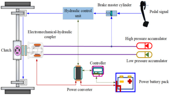
Figure 1.
Schematic diagram of electromechanical-hydraulic power coupling transmission system.
The power battery is the only power source of the entire vehicle, and the hydraulic energy of the high-pressure accumulator comes from brake regeneration or is converted by electric energy. At low speed and heavy load, the hydraulic power is utilized independently or assisted by electric power to drive the vehicle to travel, and at high speed, the electric power is mainly used. When braking, the electric power is used when the speed is high and the inertial energy is recovered to the power battery in the form of electric energy; when the speed is low, hydraulic power is used, and the inertial energy is recovered to the high-pressure accumulator in the form of hydraulic energy; if the braking intensity is large, the electric power and hydraulic power are used to brake at the same time, and the inertial energy is converted into electric energy and hydraulic energy to be stored separately [20]. The switching of the whole process is also affected by the pressure of the hydraulic accumulator and the SOC of the power cell.
The powertrain in the electromechanical-hydraulic coupling is a complete, independent energy and power conversion unit, and the corresponding vehicle is no longer a hybrid vehicle in the traditional sense. Hybrid vehicles are vehicles whose drive systems are composed of two or more individual drive systems that can operate simultaneously, and the vehicle’s driving power is provided by the individual drive systems individually or jointly according to the actual vehicle driving state. The driving power of the vehicle is provided by a single drive system alone or together according to the actual vehicle driving status; there are more than two energy/power conversion devices. Second, mechanical energy, hydraulic energy, and electric energy are coupled and transformed in the electromechanical-hydraulic coupler, and the braking energy can be recovered and stored in the form of hydraulic energy and electric energy to the hydraulic accumulator and battery for reuse [21]. Third, hydraulic power is only auxiliary power, and electric power is the main power. Therefore, a vehicle utilizing this transmission system is called an electromechanical-hydraulic power coupled electric vehicle.
2.2. The Working Principle of Electro-Hydraulic Coupling Electric Vehicle
The electromechanical-hydraulic coupled electric vehicle has different requirements for the power and minimum working pressure of hydraulic accumulators under different working conditions, etc. Therefore, we can divide the working modes into parking accumulation mode, starting acceleration hydraulic drive mode, pure electric drive mode, hybrid drive mode, and regenerative braking mode, as shown in Figure 2.
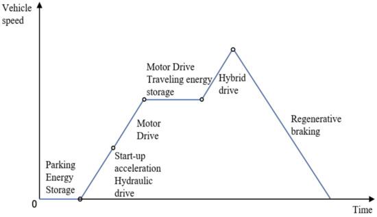
Figure 2.
Typical work cycle model.
- Parking energy storage: hydraulic power drives the vehicle to start. When the pressure in the hydraulic accumulator is higher than the minimum working pressure of the hydraulic accumulator, then the high-pressure oil in the high-pressure accumulator flows to the low-pressure accumulator through the hydraulic pump/motor, converting the hydraulic energy stored in the hydraulic accumulator into mechanical energy.
- Vehicle acceleration: electric power and hydraulic power coupling output energy together to drive the vehicle. The mechanical energy generated when the vehicle is going downhill or braking is first converted into hydraulic energy by the electromechanical-hydraulic coupler and then recovered and stored in the high-pressure accumulator. When the energy is rich, then the electric motor will convert it into electric energy and recover and store it in the battery pack, thereby improving the efficiency of energy recovery.
- When the vehicle is running at a constant speed: The vehicle is judged according to the actual situation of the working pressure in the hydraulic accumulator. When using hydraulic energy to start the vehicle, the high-pressure fluid in the high-pressure accumulator pushes the hydraulic pump/motor to rotate, converting the hydraulic energy stored in the hydraulic accumulator into mechanical energy and driving the vehicle to start. When uniform speed is reached, the battery pack starts to provide electric energy to the electric motor, and the vehicle is driven by electric power to drive.
- When the vehicle climbs/accelerates: After the vehicle starts, the electric power drives the vehicle into acceleration mode. At this time, the electric energy is converted into mechanical energy through the electric motor, which works simultaneously with the hydraulic power. The two are superimposed in the electromechanical-hydraulic coupling for torque to drive the vehicle at a higher speed.
- When decelerating and braking: The vehicle’s electric motor is used as a generator and the vehicle coasts forward under the action of inertia force. The braking energy is converted into hydraulic energy in the electromechanical-hydraulic coupler and stored in the high-pressure accumulator. At the same time, the electric motor starts to work, converting mechanical energy into electrical energy, which is stored in the battery pack through the power converter.
The new electromechanical-hydraulic power transmission system proposed in this paper effectively combines the characteristics of zero-emission and no pollution in pure electric vehicles [22] with the high energy recovery rate and high power density of the hydraulic systems in hydraulic hybrid vehicles [23], and as a result, it better meets the needs of the economy, reliability, and safety of vehicles [24].
3. Accumulator Selection
A hydraulic accumulator is a kind of auxiliary component in the hydraulic pneumatic system and is also the emergency power source in the hydraulic system. During vehicle operations with high power needs, such as vehicle start, vehicle climbing, and other working conditions, the accumulator can release the pressure oil supply hydraulic pump/motor hydraulic energy, and re-supply the hydraulic system auxiliary motor to drive the vehicle together. When the system pressure increases instantly, the accumulator can absorb this part of the energy to ensure the stability of the whole system pressure and can moderate the hydraulic system during a sharp hydraulic shock [25]. Accumulators are divided into spring type, weight type, and gas type according to the loading method [26]. The gas type accumulator is further divided into gas–hydraulic direct contact, piston type, diaphragm type, and skin type according to the structural characteristics. A comparison of the characteristics of several commonly used accumulators is shown in Table 1.

Table 1.
Characteristics of the accumulator.
According to Table 1, it is known that the spring-type accumulator has limited spring expansion and contraction, which is not suitable for high-frequency occasions; the weight-type accumulator is large and bulky, the piston-type accumulator is not sensitive, and the diaphragm-type’s capacity is small. The characteristics of various accumulators and the requirements of the hybrid transmission system are integrated [27], so this paper selects the responsive and lightweight skin-type accumulator as the energy storage element of the electromechanical-hydraulic hybrid transmission system, as shown in Figure 3.
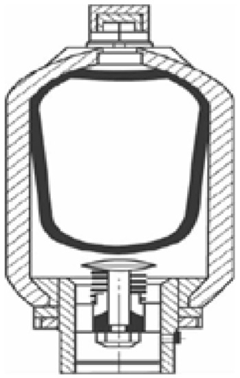
Figure 3.
Skin type accumulator.
4. Mathematical Modeling
4.1. Hydraulic Accumulator
The hydraulic accumulator is the main component of the electromechanical-hydraulic power transmission system. As an auxiliary power, it provides hydraulic power to drive the vehicle, and is also a component for braking energy storage [28]. Therefore, mathematical modeling of the hydraulic accumulator is performed [29]. The high-pressure accumulator (HPA) and low-pressure accumulator (LPA) in the pulse discharge process have a relationship between pressure (MPa) and volume (L) according to Boyle’s law as
where P0 is the initial inflation pressure of the gas in the accumulator, MPa; v0 is the inflation volume when the accumulator pressure is P0, L, at which time the skin is filled with the inner cavity of the shell, i.e., the capacity of the accumulator; P1 is the minimum working pressure of the accumulator, MPa; v1 is the gas volume when the accumulator pressure is P1, L; P2 is the maximum working pressure of the accumulator, MPa;. v2 is the gas volume when the accumulator pressure is P2, L; n is the gas multivariable index. When the gas in the accumulator is fully exchanged with the external heat, the process can be considered as an isothermal state, when n = 1; when the gas in the accumulator expands rapidly and the heat exchange is not sufficient, the process can be considered as an adiabatic state, when n = 1.4.
Regarding the performance of the accumulator, the main parameters involved are filling pressure, minimum working pressure, maximum working pressure, and accumulator volume [30].
- Determination of the minimum working pressure P1
- 2.
- Determination of the maximum working pressure P2
The maximum working pressure P2 of the bladder accumulator is determined according to the requirements of the system and the compression ratio of the bladder (b = P0/P2). From experience, the maximum working pressure P2 cannot exceed three times the minimum working pressure P1. That is, P2 ≤ 3P1. Otherwise, the gas inside the airbag will lead to the deformation of the skin bag due to rapid compression, which will shorten the life of the skin bag.
- 3.
- Determination of inflation pressure P0
Theoretically, the energy that can be stored and released by the hydraulic accumulator is
From Equation (1), we have
by substituting into Equation (3)
From Equation (1), we have
by substituting into Equation (3)
From Equation (5), it can be seen that increasing the volume of the accumulator v0 and increasing the maximum working pressure of the accumulator P2 can increase the energy stored in the accumulator. However, due to space constraints, the volume of the accumulator cannot be too large; the maximum working pressure of the accumulator cannot be too high due to the constraints of sealing and safety factors.
As a rule of thumb, the accumulator filling pressure should be set between 90% of the minimum operating pressure of the system and 25% of the maximum operating pressure of the system, that is
If P1 = P0, v0 and P2 are taken as constants. Set dE/dP0 = 0 to obtain the maximum value of energy absorbed by the accumulator.
Yielding
Let P1 = P0; substituting Equation (11) into Equation (7) yields the maximum stored energy Emax as
- 4.
- Determination of accumulator volume v0
The energy balance equation for the vehicle braking in the ideal state is
where δ is the vehicle’s rotating mass conversion factor and generally takes δ = 1.01; m is the vehicle’s mass, kg; u0 is the vehicle’s initial velocity at the beginning of braking, m/s; u is the vehicle’s speed after t moments of braking, m/s; E1 is the energy recovered by the hydraulic accumulator, J; E2 is the energy lost by the vehicle to overcome rolling friction, J; E3 is the energy lost by the vehicle to overcome air resistance.
The energy lost by the vehicle to overcome rolling friction is
where m is the mass of the vehicle, kg; g is the acceleration of gravity (taken as 9.8 m/s2); f is the rolling friction coefficient of the wheels; S is the braking distance of the vehicle, m.
The energy lost by the vehicle to overcome air resistance is
where CD is the air resistance coefficient; A is the windward area; u is the velocity of the vehicle after braking moment t; a is the deceleration of the vehicle braking.
Substituting Equations (3), (14), and (10) into Equation (13), we get
4.2. Hydraulic Pump/Motor Matching
The hydraulic system is an important part of the electromechanical-hydraulic coupling, and hydraulic power as auxiliary power is also an important part of the energy conversion process. When the vehicle is starting, the hydraulic pump/motor drives the vehicle. When the vehicle is braking, the hydraulic pump can store the excess braking energy in the form of hydraulic energy into the accumulator.
- Maximum power of hydraulic pump/motor
The maximum power consumed by the hydraulic pump/motor while the vehicle is accelerating is calculated by the formula
where Pmax a is the maximum power required in the hydraulic pump/motor-alone drive mode; ηh is the mechanical transmission efficiency from the hydraulic system to the wheels, which is 0.85; m is the mass of the vehicle; g is the acceleration of gravity (taken as 9.8 m/s2); f is the rolling friction coefficient of the wheels; umax a is the maximum vehicle speed in the hydraulic pump/motor alone drive mode; CD is the air resistance coefficient; A is the windward area; δ is the rotating mass conversion factor of the vehicle, generally taken as δ = 1.01.
- 2.
- Maximum torque of hydraulic power
The formula for calculating the maximum torque of hydraulic power is
where α is the torque adaptability coefficient, α = (1.1~1.3), α = 1.2 is selected; nmax a is the maximum power speed, and nmax a = 5350 r/min is selected.
4.3. Electric Motors
The electric drive system is the core of the electromechanical-hydraulic power-coupled vehicle, in which the electric motor can recover the braking energy during the braking process and convert it into electrical and hydraulic energy. We choose a permanent magnet synchronous motor, which has the advantages of good speed regulation characteristics, high efficiency, and compact structure.
- The equations for the mechanical power Pmec and power loss Plost of the motor are
The relationship between the mechanical power Pmec and the electrical power Pelec is
where, Pelec is the electrical power.
- 2.
- Motor/generator efficiency
4.4. Battery
The battery selected in this paper is lithium iron phosphate. A lithium iron phosphate battery has the advantages of high specific energy, high specific power, long cycle life, and good safety. The capacity of the battery pack must meet the requirements of the range of the vehicle. This paper adopts the equal speed method for calculation.
- The power required to drive the vehicle at a constant speed in purely electric mode is
- 2.
- The energy required to travel a certain distance S over an equal distance is
- 3.
- The stored energy of the battery required for electric vehicles is
- 4.
- The power cell pack energy constraint is
5. Simulation Analysis
5.1. Simulation Methodology
In this paper, AME Sim software is used to build the whole vehicle simulation parameters of the electro-hydraulic vehicle, as shown in Table 2.

Table 2.
Main parameters of the whole vehicle.
The whole vehicle simulation model of the electromechanical-hydraulic vehicle is built with the help of AME Sim software [31], as shown in Figure 4. The model mainly consists of the whole vehicle module, driver module, hydraulic hybrid system module, hydraulic hybrid control module, engine module, clutch module, etc.
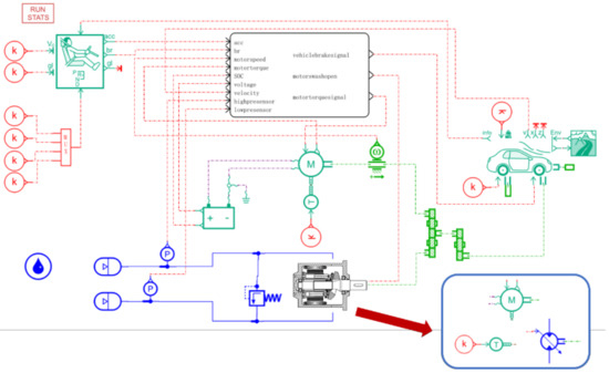
Figure 4.
Full vehicle simulation model of electromechanical hydraulic vehicle.
The control strategy for an electromechanical-hydraulic vehicle was built with the help of Simulink, as shown in Figure 5. The control strategy model mainly includes two parts: mode switching and energy management. Mode switching includes the start mode, drive mode, brake mode, and stop mode. Energy management is the different torque distribution corresponding to each mode.
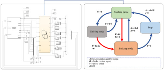
Figure 5.
Full vehicle simulation model of an electromechanical-hydraulic vehicle.
Simulink is a forward simulation that can be used to develop control strategies for the vehicle, and AME Sim is a reverse simulation that can be used to select the components of the vehicle. In this paper, we built the whole vehicle model in AME Sim, imported various working conditions of vehicle driving into it, and then created an interface that could open Simulink software so that we could realize joint AME Sim and Simulink utilization. The joint simulation technique of AME Sim and Simulink can be closer to the natural state of the vehicle with an electromechanical-hydraulic power system [32].
The work of the accumulator can be regarded as an independent thermodynamic system, its work process is the system and the external energy transfer and transformation process; the volume of the accumulator affects the entire vehicle braking performance and energy recovery effect [33].
For the effect of an energy storage volume on the working performance of the whole vehicle, in this paper, we use an AME Sim/Simulink co-simulation technique to run the simulation. The simulation input is the New European Driving Cycle (NEDC) condition, which contains four city cycle conditions and one suburban cycle condition, with a total duration of the 1180 s and a maximum speed of 120 km/h.
5.2. Determination of Energy Storage Capacity
The 20 L, 30 L, 35 L, 40 L, and 50 L hydraulic accumulators were replaced for simulation testing under the premise that the EMHCEV could follow the NEDC working speed normally. The comparison graphs of the SOC curves of the accumulator at different volumes of the vehicle battery (shown in Figure 6) and the pressure comparison graphs of the hydraulic accumulator (shown in Figure 7) were obtained through the simulation.
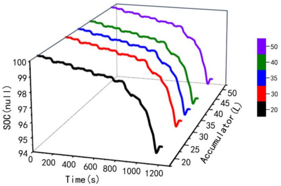
Figure 6.
Battery SOC variation curve with different volumes of the accumulator.
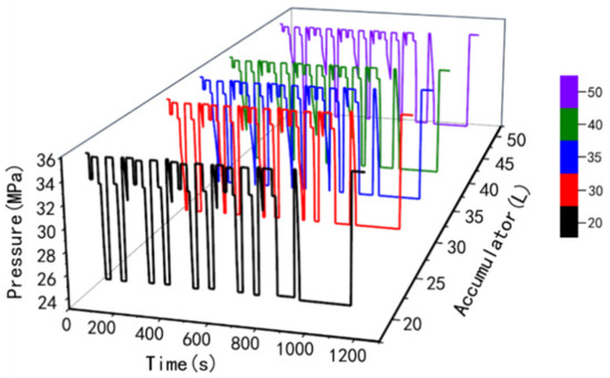
Figure 7.
Pressure variation curve of accumulator with different volumes.
Figure 6 shows the comparison of the consumption of the vehicle battery when the volume of the accumulator is different. The initial battery SOC is set to 100%, and it is clear from the curve that the larger the volume of the accumulator, the smaller the consumption of the vehicle battery instead, i.e., the volume of the accumulator is proportional to the SOC of the battery. The accumulator with a volume of 20 L can make the vehicle’s SOC value reach 94.7099%, and the accumulator with a volume of 50 L can make the vehicle’s SOC value reach 94.7890%. Therefore, the difference in volume makes little difference to the vehicle battery consumption comparison.
The larger the volume, the more energy is stored in the accumulator, but it is important to match the optimal capacity to the vehicle due to the difference in weight, maximum speed, and usage of the vehicle itself. From Figure 7, we know that the 20 L, 30 L, and 35 L accumulators can reach the maximum operating pressure of 35 MPa throughout the braking recovery phase, which ensures energy recovery efficiency. In contrast, the 40 L and 50 L accumulators are always below the maximum operating pressure throughout the brake recovery phase. Therefore, a larger volume of the accumulator may have an impact on the braking time and braking distance of the vehicle, and the larger the volume of the accumulator, the more space it takes up in the vehicle, adding a larger load to the vehicle.
On balance, a 35 L accumulator is the best choice to ensure maximum operating pressure with minimum battery consumption. The 35 L volume accumulator is the best capacity match for this type of vehicle, as it can take into account both operating pressure and battery consumption.
5.3. Speed Following
The speed following is shown in Figure 8. The NEDC speed matches well with the simulated speed, and the EMHCEV has better power performance and braking performance.
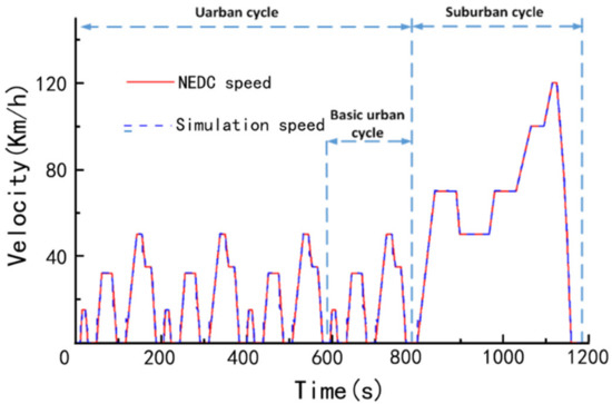
Figure 8.
Speed simulation results.
5.4. Hydraulic Power Involvement
The torque curve of the EMHCEV is shown in Figure 9, which shows the variation of the torque of the electric and hydraulic parts. The maximum total torque is up to 271 Nm. The first half of the torque phase represents the four city cycle driving conditions in NEDC operation, and the second half corresponds to the suburban operation.
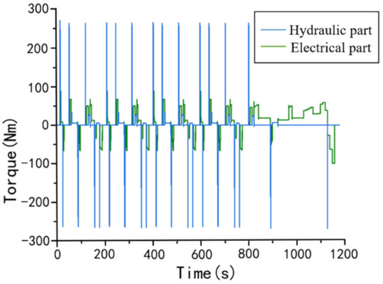
Figure 9.
Torque curve.
The swashplate opening is the inclination angle of the swashplate of the hydraulic part of the electro-hydraulic coupler, ranging between (−1, 1), representing (−20°, +20°), whose opening and closing process is shown in Figure 10 and shows that the opening and closing of the cross plate can be done instantaneously. Negative numbers represent hydraulic regenerative braking, positive numbers represent the involvement of the start-up acceleration, and the high-speed phase is not involved in the work.
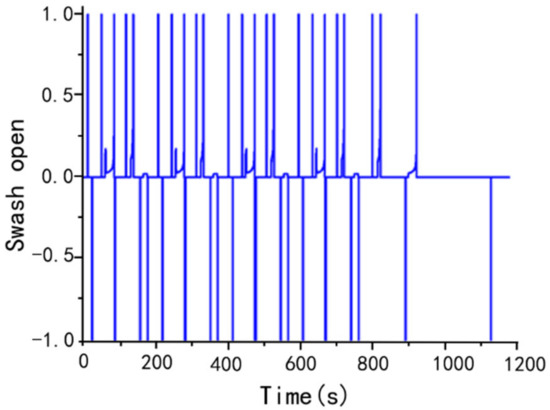
Figure 10.
Hydraulic pump swashplate opening.
6. Conclusions
In this paper, an electromechanical-hydraulic coupled electric vehicle simulation model is established in AME Sim based on the vehicle dynamics model in order to better simulate the influence of each major parameter of the accumulator on the overall operating effectiveness of the vehicle. The vehicle and related parameters are set up in conjunction with the actual situation so that the vehicle is simulated and tested under the New European Driving Cycle (NEDC) operating conditions. Through simulation tests, the effect of different volumes of hydraulic accumulators in the hydraulic system on the operating pressure and the vehicle battery consumption is investigated. From the simulation results, it can be seen that the hydraulic accumulator in the electric vehicle with the electromechanical-hydraulic coupling system used in this paper, the difference of its volume on the vehicle battery consumption is not very different, but it will affect the highest working pressure of the vehicle work, so it may have an impact on the braking time and braking distance of the vehicle. Therefore, based on practical application considerations, a hydraulic accumulator with a volume of 35 L is the best capacity for electromechanical-hydraulic coupled electric vehicles. The research work in this paper provides a basis for subsequent research to improve the energy recovery efficiency of electromechanical-hydraulic coupled electric vehicles and has a certain reference value for the research and optimization of electromechanical-hydraulic coupled electric vehicles.
Author Contributions
Conceptualization, Y.C. and T.Z.; methodology, H.Z.; formal analysis, Z.Z. and Q.J.; investigation, Y.C., H.X. and H.C.; resources, Y.C., Z.Z., Y.Z. and Q.J.; writing—original draft preparation, Y.C.; writing—review and editing, Y.C. and H.Z. All authors have read and agreed to the published version of the manuscript.
Funding
This research was funded by the National Natural Science Foundation of China, grant number 52075278, and Municipal Livelihood Science and Technology Project of Qingdao, grant number 19-6-1-92-nsh.
Conflicts of Interest
The authors declare no conflict of interest.
References
- Chen, J.S. Energy efficiency comparison between hydraulic hybrid and hybrid electric vehicles. Energies 2015, 8, 4697–4723. [Google Scholar] [CrossRef]
- Hong, J.C.; Wang, Z.P.; Chen, W.; Wang, L.Y. Multi-fault synergistic diagnosis of battery systems based on the modified multi-scale entropy. Int. J. Energy Res. 2019, 43, 8350–8369. [Google Scholar] [CrossRef]
- Du, R.; Hu, X.; Xie, S.; Hu, L.; Zhang, Z.; Lin, X. Battery aging- and temperature-aware predictive energy management for hybrid electric vehicles. J. Power Sources 2020, 473, 228–568. [Google Scholar] [CrossRef]
- Bai, Y.; He, H.; Li, J.; Li, S.; Wang, Y.X.; Yang, Q. Battery anti-aging control for a plug-in hybrid electric vehicle with a hierarchical optimization energy management strategy. J. Clean. Prod. 2019, 237, 117841. [Google Scholar] [CrossRef]
- Kouchachvili, L.; Yaici, W.; Entchev, E. Hybrid battery/supercapacitor energy storage system for the electric vehicles. J. Power 2018, 374, 237–248. [Google Scholar] [CrossRef]
- Zhuk, V.; Verbovskyi, O.; Popadiuk, I. Experimental Regulating Parameters of Bladder-Type Hydraulic Accumulator. Int. J. Appl. Mech. Eng. 2022, 27, 232–243. [Google Scholar] [CrossRef]
- Hong, J.C.; Wang, Z.P.; Yao, Y.T. Fault prognosis of battery system based on accurate voltage abnormity prognosis using long shout-term memory neural networks. Appl. Energy 2019, 251, 113381. [Google Scholar] [CrossRef]
- Yang, J.; Zhang, T.; Hong, J.; Zhang, H.; Zhao, Q.; Meng, Z. Research on Driving Control Strategy and Fuzzy Logic Optimization of a Novel Mechatronics-Electro-Hydraulic Power Coupling Electric Vehicle. Energy 2021, 233, 121221. [Google Scholar] [CrossRef]
- Yang, J.; Zhang, T.; Zhang, H.; Hong, J.; Meng, Z. Research on the Starting Acceleration Characteristics of a New Mechanical–Electric–Hydraulic Power Coupling Electric Vehicle. Energies 2020, 13, 6279. [Google Scholar] [CrossRef]
- Sun, Y.; Zhang, H.; Yang, J. The Structure Principle and Dynamic Characteristics of Mechanical-Electric-Hydraulic Dynamic Coupling Drive System and Its Application in Electric Vehicle. Electronics 2022, 11, 1601. [Google Scholar] [CrossRef]
- Jin, Y. Realization of hydraulic simulation system of YT4543 machine tool power slide based on Fluid SIM software. J. Beijing Inst. Ind. Technol. 2012, 11, 13–19. [Google Scholar]
- Wan, L.R.; Gong, Y.Q.; Wang, C.L. Study on Hydraulic Circuit Simulation Based on MSC·EASY5 for the Arm of Excavator. J. Adv. Mater. Res. 2011, 1335, 291–294. [Google Scholar] [CrossRef]
- Fang, J.; Yang, G. Simulation and experimental analysis of hydraulic hammer system based on DSH plus. Mach. Tools Hydraul. 2014, 42, 25–29. [Google Scholar]
- Lei, X. Simulation Analysis of Hydraulic System Test Bed of Concrete Pump Truck Boom Based on Hypneu; Guangxi University of Science and Technology: Liuzhou, China, 2019. [Google Scholar]
- Song, C.; Kum, D.; Kim, K.S. Feasibility analysis and performance evaluation of a novel power-split flywheel hybrid vehicle. Energies 2018, 11, 1744. [Google Scholar] [CrossRef]
- Zhou, S.L.; Walker, P.; Zhang, N. Parametric design and regenerative braking control of a parallel hydraulic hybrid vehicle. Mech. Mach. Theory 2019, 146, 103714. [Google Scholar] [CrossRef]
- Zhu, F.Q.; Yang, Z.P.; Lin, F.; Xin, Y. Synthetic optimization of traction power parameters and energy storage systems in urban rail transit. Trans. China Electrotech. Soc. 2019, 3, 579–588. [Google Scholar]
- Ding, G.B.; Shi, Z.Q.; Cui, H.; Huang, Y.S. New Method of Increasing Working Volume of a Certain Type of Hydraulic Accumulator. Appl. Mech. Mater. 2014, 3558, 972–975. [Google Scholar] [CrossRef]
- Zhao, Q.; Zhang, H.; Xin, Y. Research on Control Strategy of Hydraulic Regenerative Braking of Electrohydraulic Hybrid Electric Vehicles. Math. Probl. Eng. 2021, 2021, 5391351. [Google Scholar] [CrossRef]
- Zeng, X.H.; Wu, Z.Q.; Wang, Y.; Song, D.; Li, G. Multi-mode energy management strategy for hydraulic hub-motor auxiliary system based on improved global optimization algorithm. Sci. China Technol. Sci. 2020, 63, 2082–2097. [Google Scholar] [CrossRef]
- Yu, Y.-X.; Ahn, K.K. Energy Regeneration and Reuse of Excavator Swing System with Hydraulic Accumulator. Int. J. Precis. Eng. Manuf.-Green Technol. 2019, 7, 859–873. [Google Scholar] [CrossRef]
- Raja, T.A.S.; Lakshmi, N.S.; Kumar, K.V.S.; Kumar, A.N. Parallel Battery Management System for Electric Vehicles. Int. J. Recent Technol. Eng. (IJRTE) 2020, 8, 4697–4700. [Google Scholar] [CrossRef]
- Xu, L.; He, X.; Shen, X. Improving Energy Recovery Rate of the Regenerative Braking System by Optimization of Influencing Factors. Appl. Sci. 2019, 9, 3807. [Google Scholar] [CrossRef]
- Moral, M.J.; Jaumandreu, J. Automobile demand, model cycle and age effects. Span. Econ. Rev. 2006, 9, 193–218. [Google Scholar] [CrossRef][Green Version]
- Hillesheim, T. Hydraulic Accumulator Increases Driving Comfort and Safety for Forklift Trucks. ATZheavy Duty Worldw. 2020, 13, 40–43. [Google Scholar] [CrossRef]
- Niu, G.; Shang, F.; Krishnamurthy, M.; Garcia, J.M. Evaluation and selection of accumulator size in electric-hydraulic hybrid (EH2) powertrain. In Proceedings of the 2016 IEEE Transportation Electrification Conference and Expo (ITEC), Dearborn, MI, USA, 27–29 June 2016; pp. 1–6. [Google Scholar] [CrossRef]
- Paswan, R.; Das, J.; Kumar, N.; Kumar, A.; Mishra, S.K.; Sujit, K. Simulation Study on Different Energy Efficient Hydraulic System: An Overview. Appl. Mech. Mater. 2014, 3304, 2234–2238. [Google Scholar] [CrossRef]
- Liu, Y.; Xu, Z.; Hua, L.; Zhao, X. Analysis of energy characteristic and working performance of novel controllable hydraulic accumulator with simulation and experimental methods. Energy Convers. Manag. 2020, 221, 113196. [Google Scholar] [CrossRef]
- Pfeffer, A.; Glück, T.; Kemmetmüller, W.; Kugi, A. Mathematical modelling of a hydraulic accumulator for hydraulic hybrid drives. Math. Comput. Model. Dyn. Syst. 2016, 22, 397–411. [Google Scholar] [CrossRef]
- Castellanos, L.S.M.; Noguera, A.L.G.; Velásquez, E.I.G.; Caballero, G.E.C.; Lora, E.E.S.; Cobas, V.R.M. Mathematical modeling of a system composed of parabolic trough solar collectors integrated with a hydraulic energy storage system. Energy 2020, 208, 118255. [Google Scholar] [CrossRef]
- Zhao, Q.; Duan, J.J.; Wang, C. Modeling and Simulation of Vehicle Hydraulic ABS Based on AMEsim. Adv. Mater. Res. 2012, 2075, 441–445. [Google Scholar] [CrossRef]
- Fang, G.H.; Zheng, W.S.; Zhang, L.B. Modeling and Simulation Based on AME Sim and Simulink Electric Hydraulic Power Steering System. Adv. Mater. Res. 2013, 2428, 1150–1153. [Google Scholar] [CrossRef]
- Juhala, J.; Kajaste, J.; Pietola, M. Experimental analysis of heat losses in different types of hydraulic accumulators. In Proceedings of the ASME 8th FPNI Ph.D Symposium on Fluid Power, Lappeenranta, Finland, 11 June 2014; pp. 2014–7838. [Google Scholar]
Publisher’s Note: MDPI stays neutral with regard to jurisdictional claims in published maps and institutional affiliations. |
© 2022 by the authors. Licensee MDPI, Basel, Switzerland. This article is an open access article distributed under the terms and conditions of the Creative Commons Attribution (CC BY) license (https://creativecommons.org/licenses/by/4.0/).