1. Introduction
In the last two decades, researchers proposed several alternatives to CMOS-based computing. Among them, particular attention has been paid to the so-called Quantum-dot Cellular Automata (QCA) [
1]. The general QCA cell is a squared arrangement composed of four quantum dots and two repelling electrons. Thanks to Coulomb’s repulsion, the two electrons occupy the antipodal sites of the QCA cell, making it possible to encode two distinct logic states.
Various technologies have been proposed to implement the QCA paradigm, such as metallic, magnetic, and molecular implementations [
2,
3,
4,
5]. Among these, the molecular Field-Coupled Nanocomputing (FCN) is one of the most promising, as it is expected to allow very high-frequency operations at ambient temperature and very high devices density [
6,
7]. In detail, the molecular FCN paradigm realizes computational electronic devices by encoding the information in the charge distribution of molecules. Generally, the electrons of the QCA paradigm are replaced by a more general electron cloud that aggregates on specific points of the molecule, acting as QCA quantum dots [
5,
8].
Most of the literature considers all QCA devices as possible molecular FCN devices. Consequently, the QCA circuits are generally analyzed using the quantum two-state approximation and generally considered valid in any QCA technology despite the actual implementation. Most of the works designing molecular FCN circuits take for granted that molecular cells perfectly fit general QCA paradigms. However, molecular FCN differs from the general QCA paradigm for specific aspects related to molecular physics. Until now, only a few works have tried to link the quantum approximations used in the QCA theory to the molecular behavior, mainly for the switching of the molecules [
9,
10]. Nevertheless, many other properties play a relevant role in the molecular interaction, such as the electrostatic characteristics and the possible presence of the counterion [
11,
12].
Over the last few years, several molecules have been proposed as candidates for implementing molecular FCN technology [
8,
12,
13,
14]. All of them are different, yet, the behavior is just taken for granted as consistent with QCA technology, and there is no apparent awareness of the effect that physical molecular properties have at the circuit level.
In this work, by exploiting three reference molecular species (neutral, oxidized, and zwitterionic), we analyze different device layouts from both a theoretical and a quasi-physical point of view. In particular, we perform simulations with two available simulators: the Self-Consistent Electrostatic Potential Algorithm (SCERPA) [
11,
15] and QCADesigner [
16,
17]. This way to proceed allows us to highlight the link between the molecule characteristics and the functional behavior of devices. Thus, this work demonstrates the importance of considering the molecular type during the molecular FCN design process. Indeed, neglecting the molecular species and assuming the molecules copying the QCA behavior leads to controversial molecular circuits proposals, and it slows down the essential assessment of molecular FCN as a possible candidate for future digital electronics. In addition, the analysis in this work guides chemists to synthesize suitable molecules for molecular FCN and to improve the ability of electronics engineers to design molecular FCN circuits with awareness of the physical behavior of the molecule.
2. Background
This section describes the basics of the general QCA paradigm by explaining information encoding and propagation. Then, it analyses the key points of the molecular FCN intended as a possible implementation of the QCA. Next, we describe the significant characteristics of molecular technology, such as the fundamental devices, the clock, and the associated modeling tools. Finally, we list some molecules proposed in the literature for implementing the technology, and we introduce the electrostatic properties of the oxidized, neutral and zwitterionic species.
2.1. The General QCA Paradigm and the Molecular Field-Coupled Nanocomputing
In the general QCA paradigm, four quantum dots and two charges compose the so-called QCA cell [
1]. The two charges dispose on the antipodal quantum dots in order to minimize the electrostatic energy, leading to two equivalent minimum-energy states that associate to logic ‘0’ and logic ‘1’, as
Figure 1a shows. Additionally, by placing several cells in a row, information propagates thanks to Coulomb’s force: nearby cells interact through the electrostatic coupling of the fields generated by the presence of localized charges. The peculiarity of the QCA paradigm is the absence of charge transport between cells, which promises very high-speed operations and very low-power consumption of circuits [
6].
One way to technologically implement the QCA paradigm is to use a couple of molecules to build a cell, defining the so-called molecular FCN [
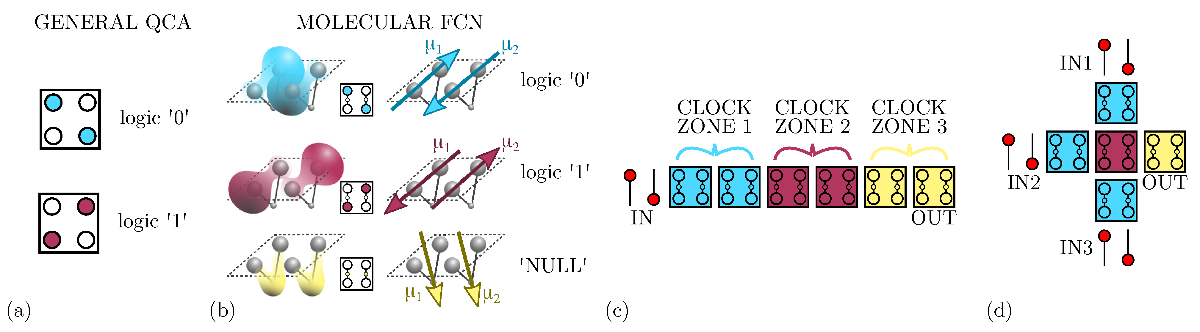
5]. As
Figure 1b shows, the molecules belonging to the same cell exhibit two opposite dipole moments (
and
), mimicking the presence of the two charges in two of the four quantum-dots of QCA cells and encoding the logical states ‘0’ and ‘1’. By using molecules to implement the paradigm, we gain two more advantages: the possibility to build very small devices [
7] and the possibility to work at room temperature [
18].
As
Figure 1b shows, besides the basic implementation of the two logic states, a third state named ‘NULL’ is used to encode no information. The ‘NULL’ state is needed to implement adiabatic and pipelined propagation, accomplished by applying an external electric field, named clock field. Indeed, by aligning several molecular cells, it is possible to propagate the information through FCN wires [
19], as depicted in
Figure 1c. The partitioning of the molecular wire into clock zones, which are activated sequentially through the clock field, allows the information to be guided, eventually avoiding information aberrations during propagation and diminishing the power consumption [
11]. Placing cells in ordered structures makes it possible to implement logic functions or interconnections.
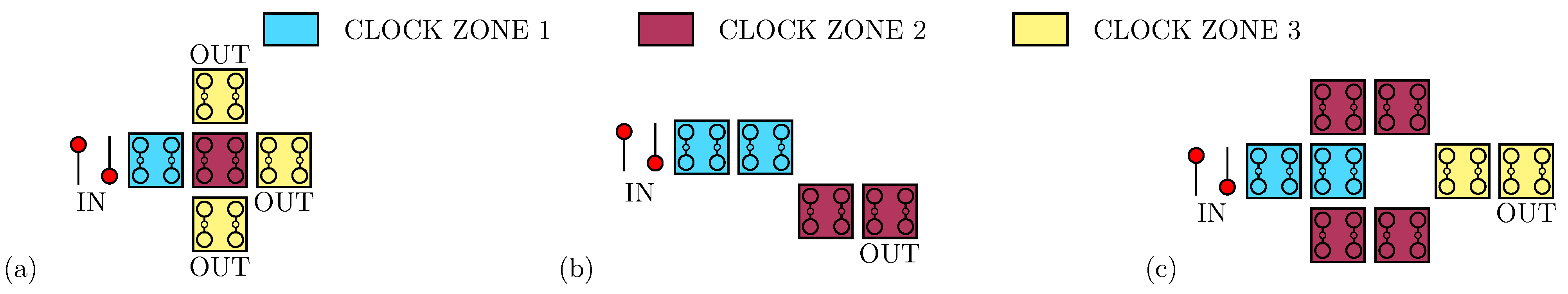
Figure 1d shows the three-inputs Majority Voter (MV), whose output matches the logic value present on the majority of its inputs [
11]. Among the possible devices, the fanout gate, shown in
Figure 2a, triplicates the information encoded by the input cell to three output wires. Another elementary logic gate is the inverter, for which two different layouts exist in literature: the single-branch inverter shown in
Figure 2b and the double-branch inverter shown in
Figure 2c.
2.2. Modelling of Molecular FCN Electrostatics
The decisive mechanism involved in the propagation and elaboration of the information encoded into cells is the electrostatic behavior of a single molecule, which is generally studied through
ab initio calculation [
5]. However, because of the intensive computational requirement needed to solve Schrodinger’s equation,
ab initio analysis becomes impracticable for systems involving many molecules. As a consequence, a methodology named MoSQuiTo (Molecular Simulator Quantum-dot cellular automata Torino) has been proposed: it lies on the physical characteristics of molecules and allows to study systems composed by a large number of molecules by describing them as electronic devices [
8,
20]. This methodology follows three steps: analysis and characterization of a single molecule through
ab initio calculations, extraction of the electrostatic characteristics and definition of high-level figures of merit, and simulation of devices using the figures of merit extracted in the previous step. Specifically, the MoSQuiTo methodology allows considering the molecule as an electronics device with proper input and output.
Among the figures of merit [
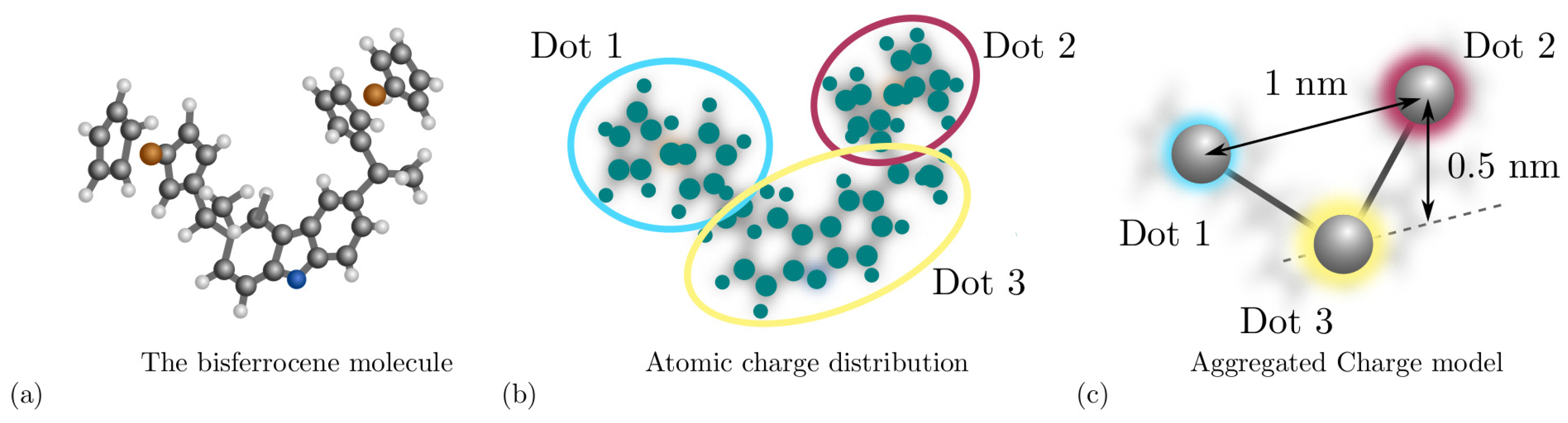
8], the Aggregated Charge (AC) models the charge distribution of a molecule. For example, considering the bis-ferrocene molecule, ad hoc synthesized for molecular FCN computing [
21] and depicted in
Figure 3a, it is possible to obtain the atomic charges by fitting the electrostatic potential from ab initio calculation.
Figure 3b shows the atomic charges and the functional groups permitting the derivation of the AC, indeed the AC is the sum of the atomic charges composing a functional group of the molecule. As depicted in
Figure 3c, functional groups constitute the equivalent of the QCA dots in the molecular FCN paradigm. Another fundamental quantity defined in the second step of the MoSQuiTo methodology is the input voltage of a molecule, defined as the voltage between the two logic dots and generated by all the electric fields surrounding the considered molecule. By relating the behavior of the AC for different input voltages, we obtain the Voltage-Aggregated Charge Transcharacteristic (VACT). Using VACTs to describe the electrostatic behavior of molecules allows simulating circuits composed of several molecules keeping a connection with the physical behavior. The SCERPA tool exploits a self-consistent procedure that enables circuit analysis based on molecule VACTs and geometries [
11,
15]. QCADesigner is an alternative tool intended for the analysis of general QCA circuits [
16] and their dynamic behavior based on the two-state approximation. QCADesigner-E version also allows evaluating the power dissipation by studying the interaction between the ideal QCA cell and the environment [
17]. The integration of molecule time evolution in SCERPA enabling the evaluation of circuit transients is still under development. Nevertheless, some work started with the modeling of molecule dynamics based on time-dependent ab initio calculation [
18]. QCADesigner also integrates a Graphical User Interface (GUI), which makes simple the handling of the circuit drawing and simulation.
2.3. Molecular Candidates and Species
At the state-of-the-art, three molecular species have been considered possible candidates for molecular FCN: neutral, zwitterionic, and oxidized molecules. The neutral molecules exhibit a net molecular charge equal to zero. Similarly, zwitterionic molecules exhibit a net molecular charge equal to zero, even presenting a localized positive charge on specific functional groups: the neutrality is guaranteed by incorporating in the molecule a negative charged group named counterion [
14]. On the other hand, the oxidized molecules are charged cation, thus showing a 1 a.u. net charge, where a.u. is the atomic unit of charge and equals the electron charge. However, in a recent work, we pointed out that a circuit composed of oxidized molecules requires counterions that guarantee the neutrality of each molecule to avoid crosstalk effects [
11]. Oxidized molecules with counterions become electrostatically similar to zwitterionic molecules; indeed, the net charge is null, yet they show positive localized charges on the logical dots. Nevertheless, it is well-known that the counterion disturbs the electrostatic characters of the intermolecular interaction [
22].
Among the proposed molecules, diallyl-butane, decatriene, and bis-ferrocene have been analyzed both as neutral and oxidized molecules [
8]. At the same time, zwitterionic molecules [
13] are in general very promising since the counterion position is fixed [
12] making the electrostatic effects more predictable and controllable. Currently, the research for new molecules providing encoding, switching, and propagation capabilities is still open. Researchers should also take into account the difficulties in the synthesis and deposition of the molecules on an eventual surface [
23].
3. Methodology
This section discusses the modeling and computational method used to analyze the molecular FCN technology and to understand the cross-implication between the molecular properties and the information propagation and elaboration.
3.1. Reference Molecular Model
To highlight the different device behaviors caused by the molecular species, we define a standard structure and conceptual characteristics for each molecule: neutral, oxidized, and zwitterionic. Working in terms of models allows us to make consistent observations with fewer geometry-dependent influences compared to using real molecules.
Figure 3c shows the relative position of the three dots of the conceptual molecules we consider in this work. In particular,
Dot 1 and
Dot 2 are generally referred to as
logic dots, since they are the ones used to encode the digital information. The
Dot 3 is used to encode the NULL state and eventually hosts the counterion of zwitterionic molecules. The relative dot positions of the conceptual molecule have been chosen considering the typical size of molecules used in molecular FCN. The following quantitative analyses are based on the mentioned geometry, although the derived considerations are also valid with other possible molecular sizes.
Moreover, the molecular species and the clock value vary how the dot charges depend on the input voltage. In this work, we consider the case in which the clock forces the charge distribution to occupy the logic dots. Based on literature results [
24], we choose Equation (
1) as a reference VACT to describe the behavior of the logic dot AC, varying the input voltage
. Each AC is denoted as
, where
i represents the
i-th dot of the molecule
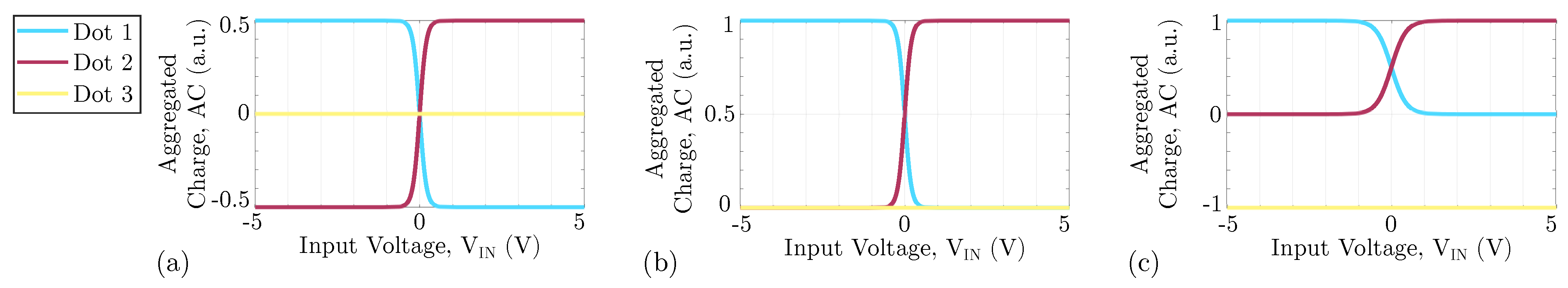
We consider literature results [
8] to derive reference ideal VACTs, which model a possible molecules suitable for FCN. The reference VACT for neutral molecules for enabling clock, is reported in
Figure 4a, where the AC of the logic dots follows the trend of Equation (
1) shifted by 0.5 a.u.
Figure 4b shows the VACT for an oxidized molecule when the clock is enabling the logic value encoding. As we said, oxidized molecules are positive ions. Therefore, if the counterion is not present, the sum of the three curves is constant to 1 a.u.
Figure 4c shows the VACT of the zwitterionic molecule, which present an intermediate behavior between the other two molecule types: the AC of the logic dots equals precisely that of the oxidized molecule. However, the molecule is globally neutral, so a constant negative charge is present on
Dot 3, creating a not-null dipole moment at the thermal equilibrium. Following the employed model, notice that ideal oxidized molecules with a counterion and zwitterionic molecules show the same electrostatic behavior.
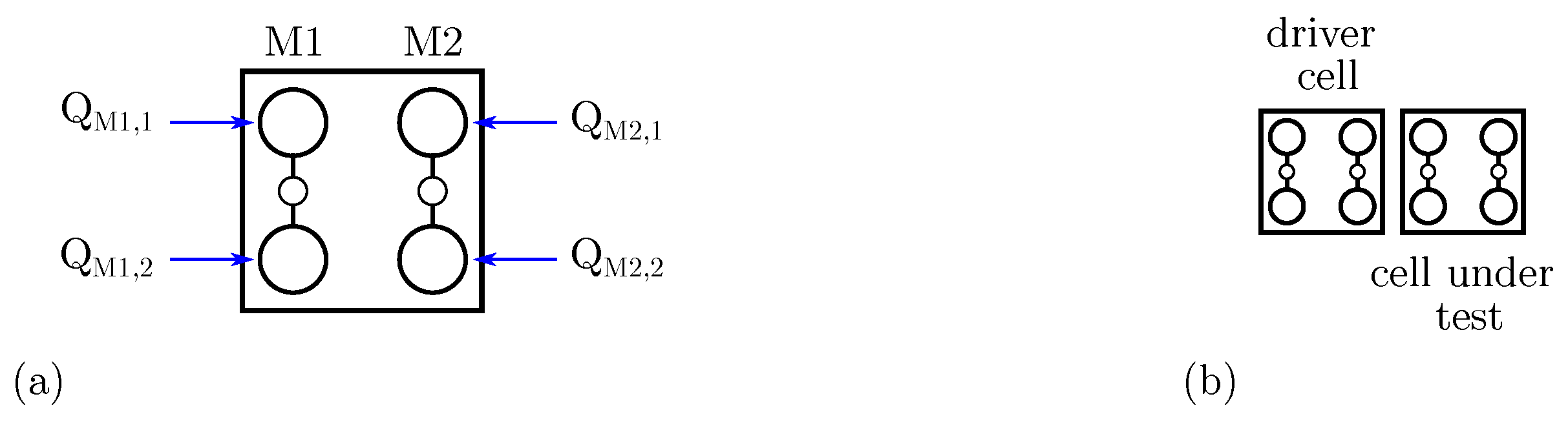
To link the molecular FCN cell with the general QCA paradigm, we combine the QCA polarization and the molecule AC.
Figure 5a shows the molecular cell composed by two molecules
(with logic dot charges
and
) and
(with logic dot charges
and
). The polarization of the cell can be defined, according to the QCA paradigm, as:
In particular, the cells with polarizations
and
are those propagating logic values ‘0’ and ‘1’, respectively.
3.2. Energy Modeling
The molecule is approximated as a distribution of aggregated charges
, associated with the input voltage according to the Equation (
1). In a system of two molecules, denoted as molecule
Mol a and
Mol b, the interaction energy can be evaluated as:
where
denotes the Euclidean distance between the two generic charges
and
. In a circuit composed by several molecules, the total energy may be evaluated as:
To justify the differences caused by the molecular species, we analyze the fundamental cell-to-cell interactions permitting information propagation and computation by analyzing the electrostatic energy. Therefore, we consider a system as the one depicted in
Figure 5b, composed by two molecular cells (i.e., four molecules), here denoted
Driver Cell (
DrC) and
Cell Under Test (
CUT). By using Equation (
4), we can evaluate the energy of the two-cell system when cells encode some logic information. We define
as the system energy when the DrC and the CUT encode logic values
X and
Y (i.e., ‘0’ or ‘1’), respectively.
From an energy point of view, the energies are associated with the DrC and CUT polarizations, and , respectively:
For , polarizations are and
For , polarizations are and
For , polarizations are and
For , polarizations are and
The energy
is then evaluated as:
where
is the electrostatic energy of the DrC-CUT charge system, whereas
and
are the electrostatic energies of the DrC and CUT cells when encoding logical values
X and
Y, respectively. All the three mentioned contributions are evaluated with (
4).
An essential quantity associated to the system energy, with molecular cells encoding logical value, is the Kink Energy (
) [
5]. Considering again
Figure 5b,
is defined as the difference between the energy of the system with DrC and CUT encoding the same logic (
or
) and the energy of the configuration encoding different logic values (
or
). In this work, we define the Kink Energies
and
according to the driver logic, as:
Notice that does not consider the electrostatic energy, resulting in the interaction between charges of the same molecular cell, making mainly due to the interaction among cells.
According to the authors’ knowledge,
and
are never distinguished in the general QCA paradigm, yet are assumed to be equal. This work will show that the two
and
may differ according to the molecular species and that there is a direct link between the functional behavior of the device and the Kink Energy differences. For this purpose, we here define the Kink Error
:
The Kink Error () measures the dependence of the interaction on the driver cell. A non-null Kink Error implies a non-symmetric interaction concerning the two different logic inputs. The Kink Error will be denoted , , and when referred to neutral, oxidized, and zwitterionic species.
3.3. Simulation Tools
In this work, we analyze zwitterionic, oxidized, and neutral molecules. We classify and discuss the electrostatic behavior of each molecular species and report the main system-level consequences. We analyze molecular circuits with the SCERPA algorithm in order to consider the effective behavior of the molecules [
15].
The SCERPA algorithm considers each molecule as an electronic device whose primary status variable is the aggregated charge
, which depends on the input voltage
of the molecule. Each input voltage is evaluated by integrating the electric field generated by the surrounding molecules on a path connecting the two logic dots. Therefore, the SCERPA algorithm iteratively evaluates molecule input voltages and applies the VACT to evaluate the molecular charge. Mathematically, the SCERPA tool solves the equation:
where
is the voltage generated by possible driver molecules on the
i-th molecule. Then,
is the
-th AC of the
j-th molecule and depends on the input-voltage of molecule (
) through the VACT associated to the clock field value of the
j-th molecule (
).
and
are the distances between the
-th AC and
i-th molecule logic dots:
Dot 1 and
Dot 2, respectively.
In the literature, another tool named QCADesigner [
16] is widely used to simulate QCA devices, inferring that they can be implemented with molecules. However, this tool is intended for the general QCA paradigm and not specifically for molecular implementation. Moreover, the QCADesigner tool mainly bases its calculations on the concept of kink energy, which is assumed to be input-independent. In this work, we discuss the possibility of using the general QCA paradigm to analyze molecular circuits, finally declaring and clarifying the scope of QCADesigner and the relation between molecular FCN and the general QCA paradigm.
Therefore, in this work, we also perform a simulation exploiting the QCADesigner bistable engine implemented in QCADesigner-E [
16,
17]. Once we have defined the polarization according to Equation (
2), QCADesigner evaluates, in a self-consistent procedure, the QCA cell non-linear response equation:
In Equation (
9),
is the Kink Energy between
i-th and
j-th molecule, whereas
is the tunneling potential, thus the coefficient used to describe the switching of the QCA cell between polarization +1 and −1, which is eventually modulated by an external clock to guide the information propagation.
In this work, we use QCADesigner-E with the default configuration in order to study the QCA cells within the general paradigm: convergence tolerance: 0.001; radius of effect: 65 nm; relative permittivity: 12.9; clock high: 9.8 × 10 J; clock low: 3.8 × 10 J; clock shift: 0; clock amplitude factor: 2; layer separation: 11.5 nm; maximum iterations per sample: 100. Concerning size, cell width: 18 nm; cell height: 18 nm; dot diameter: 5 nm.
4. Results: Basic Interactions
The results show the main differences at the system level induced by the electrostatics of the molecular species. In particular, we first discuss from an energetic point of view the fundamental cell-to-cell interactions we can find in a circuit, namely parallel and diagonal interactions, for all the molecular species we consider. After that, we focus on the simulation of a few devices relating their logical behavior to the electrostatic effects of the fundamental interactions, demonstrating the cross-implications between molecular physics and circuit behavior, thus the importance of considering the effective behavior of molecules in simulation tools.
In all the reported analyses, the intermolecular distance is fixed to 1 nm for all the analyzed circuits. Unless specified differently, the counterion of the zwitterionic molecule is positioned 0.5 nm below the logic dots. Moreover, the cells are made of two independent molecules oriented along the same direction, independently from the propagation direction.
4.1. Adjacent Cell-to-Cell Interaction
In this section, we analyze from an energy perspective two adjacent molecular cells, named Driver Cell (DrC) and Cell Under Test (CUT), to figure out the effects molecular species have on the fundamental interaction involved in the information propagation.
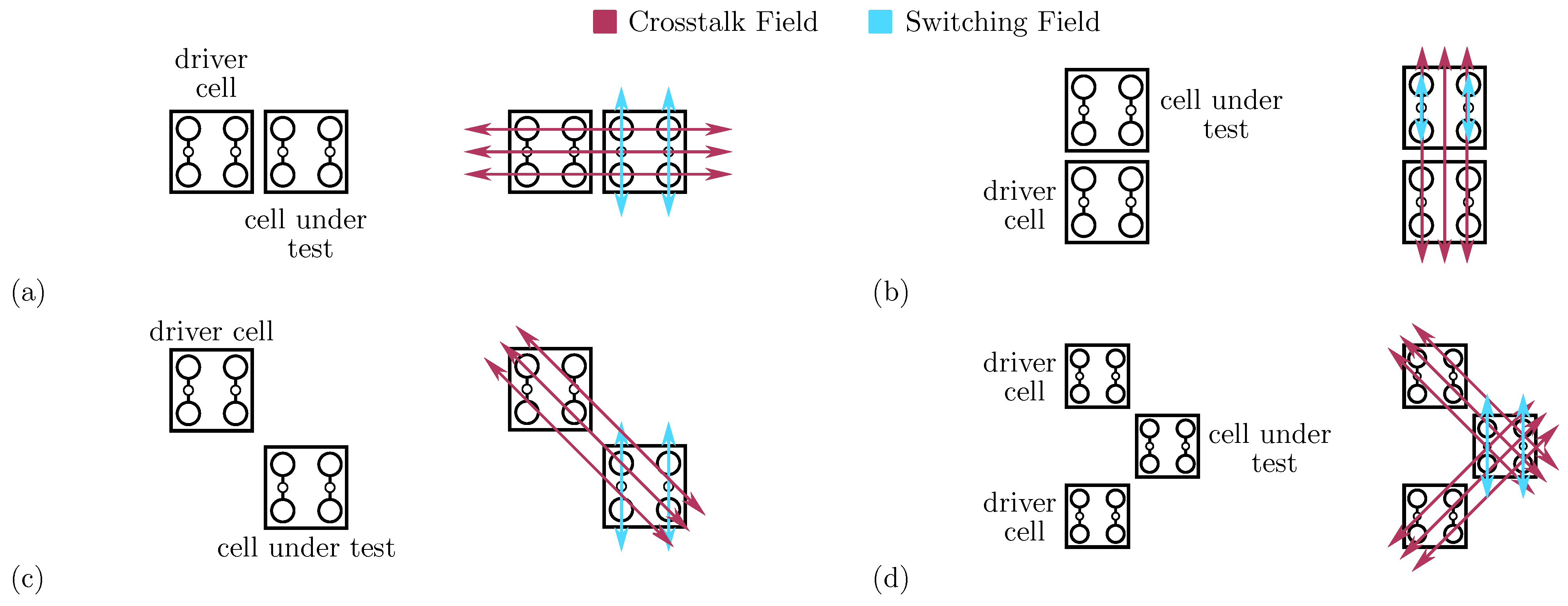
Figure 6a depicts the molecular circuit used to study the horizontal adjacent interaction. Thus, we evaluate the electrostatic energy of the four possible logic configurations (
,
,
, and
) by considering the three molecular species: oxidized, neutral, and zwitterionic molecules. In the case of correct information propagation, the CUT copies the information of the DrC. From an energy perspective, information propagation is achieved if
and
.
Table 1 reports the energies of the four possible combinations
.
With neutral molecules, the energy with equal logic information ( and ) is negative, whereas it is positive when evaluated for opposite logic values ( and ). This result satisfies the relations and , promoting correct information propagation. The two inequalities are also satisfied for oxidized and zwitterionic molecules. The presence of positive charges in oxidized molecules makes the interaction purely repulsive, leading to positive energy values. Concerning the zwitterionic species, the presence of the counterion mitigates the effects of the oxidized molecules, leading to a reduction of the obtained energies.
To evaluate the stability of the interaction and the dependence with the molecular species, we evaluate the Kink Energy according to Equation (
6). For the three species, the two Kink Energies are equal (
eV), and the Kink Errors
are null.
For all the molecular species, the logic encoded by the DrC does not influence the interaction. Thus, the adjacent horizontal interaction is not driver-dependent.
Figure 6b depicts the second adjacent interaction we can find in a circuit. In the adjacent vertical interaction, the DrC and the CUT are vertically aligned. Following the general QCA paradigm, the vertical cell-to-cell interaction equals the horizontal one. Therefore, an eventual energy analysis provides the same results as the adjacent horizontal interaction. However, the field generated by the charges composing the DrC, shown in
Figure 6b, is radial and may influence the interaction. Contrarily to the case of the adjacent horizontal interaction, the radial electric field (
Crosstalk Field) superposes the electric field enabling molecule switching and the information propagation (
Switching Field). The Crosstalk Field influences the molecule polarization individually. Additionally, the two molecules composing the CUT are independent in this specific implementation, differently from the general QCA paradigm that allows antipodal charge configurations only. Therefore, to rigorously analyze the interaction, removing the assumption of having only diagonal charge distributions on the molecular cell is necessary.
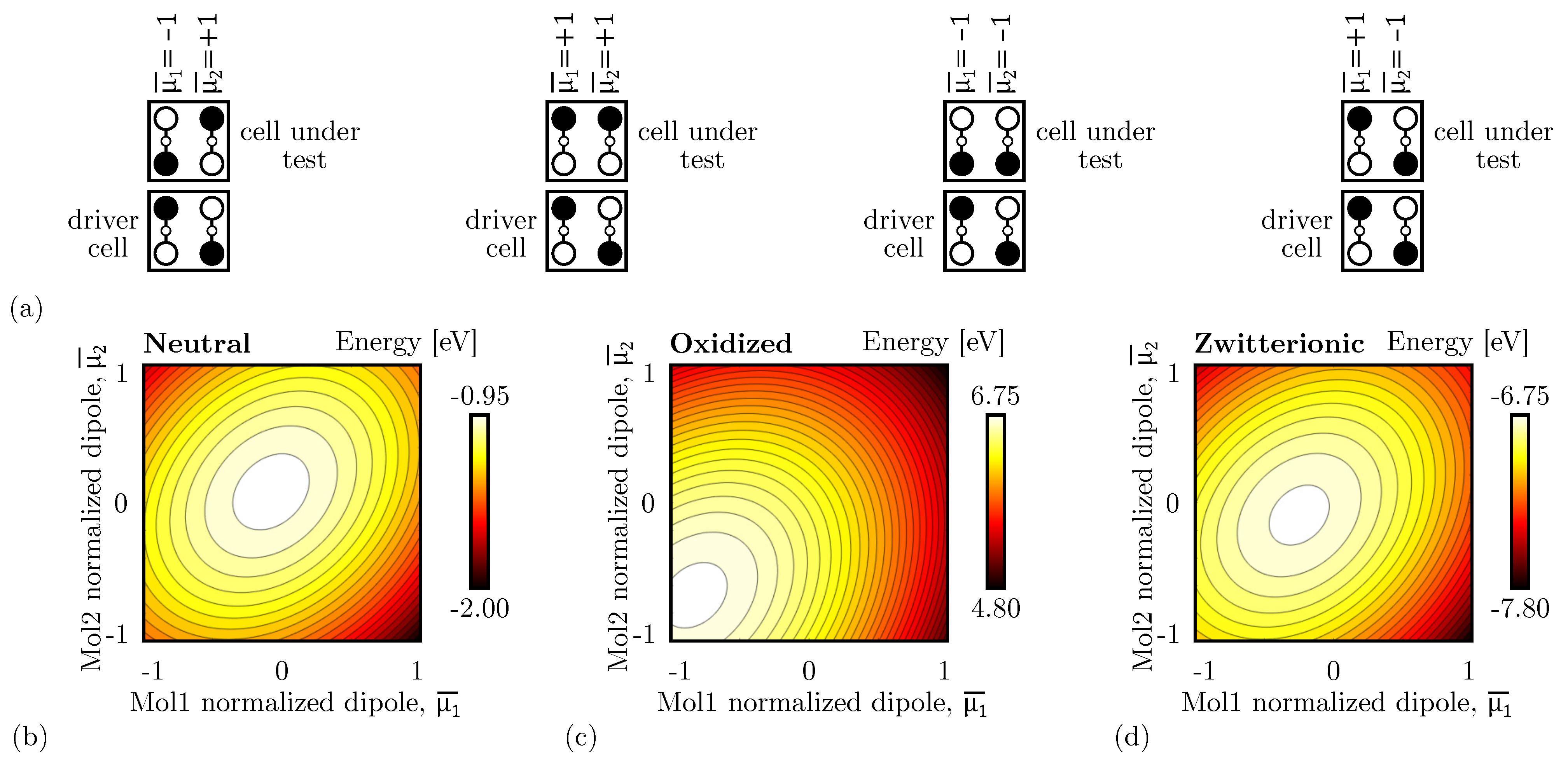
To demonstrate the crosstalk effect in adjacent vertical interactions, we consider the system shown in
Figure 6b, in which the DrC has a fixed logic value ‘0’, and we evaluate the energy of the system linearly varying the normalized dipole moment
and
of the two molecules composing the CUT between −1 and +1.
Figure 7a shows the four limit configurations that we obtain by removing the constraint of having only antipodal configurations.
Figure 7b shows the energy analysis performed with neutral molecules. For the sake of clarity, the total energy in the four limit configurations is also reported in
Table 2. To best fit the molecular technology,
Table 2 also reports the energy without considering the electrostatic contribution of charges within the same molecule, thus considering intermolecular interactions only. The analysis demonstrates a global minimum when
and
. That dipole moment configuration corresponds to the case of correct information propagation, thus the CUT encodes the same logic of DrC. The Crosstalk Field does not impinge on the vertical interaction.
Contrarily, as
Figure 7c shows, with oxidized molecules, the energy global minimum moves to the
and
configuration, which means that the most stable configuration is the one with both the CUT AC are as far away as possible from the DrC. Specifically, the crosstalk influence is maximum for oxidized molecules.
With zwitterionic molecules, the negative counterion neutralizes the molecule and reduces the generated crosstalk field. The situation mimics the case of neutral molecules, as shown in
Figure 7d.
In conclusion, the adjacent vertical interaction is sensitive to the molecular species. In particular, the field generated by the molecule charges blocks the correct propagation of the information if molecules are oxidized. The reported results highlight that the molecular species must be considered when simulating molecular FCN devices involving vertical cell-to-cell interactions.
4.2. Single Diagonal Cell-to-Cell Interaction
We now study the properties of the single diagonal interaction, which is essential to achieve the inversion operation in QCA technology. Thus, we study the diagonal interaction from an energy perspective to investigate the effects of the three molecular species on the single diagonal interaction.
Figure 6c shows the schematic used to study the single diagonal interaction, composed of a DrC and a CUT. Therefore, we linearly vary the driver polarization (
) and the CUT polarization (
) from ‘−1’ to ‘+1’.
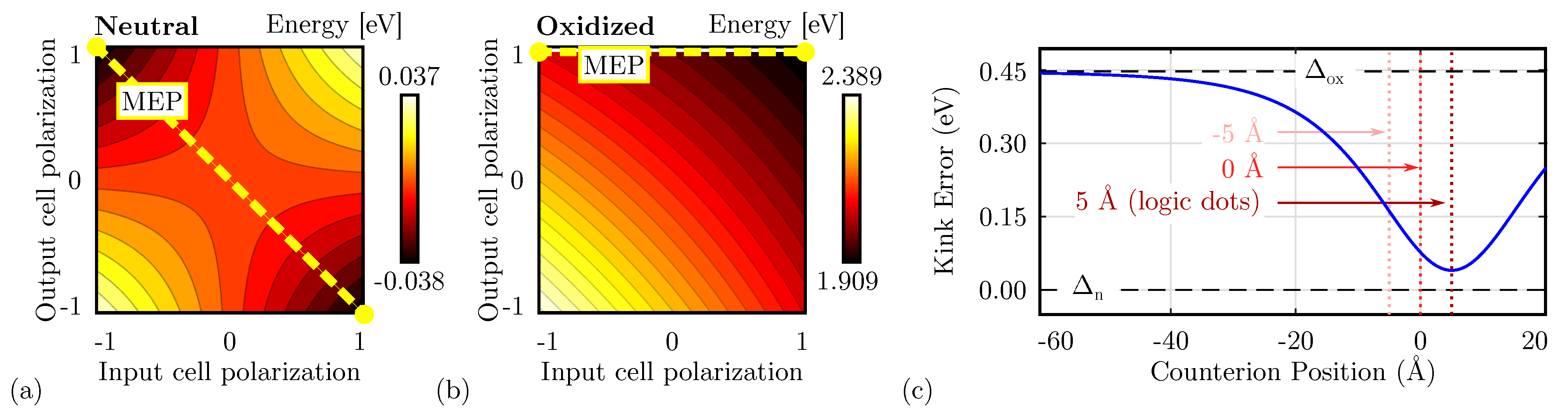
Figure 8a shows the total energy evaluated as a function of the two polarizations evaluated for neutral molecules. The energy minima are positioned where the cell polarizations are opposite, confirming that the circuit is stable when the two cells encode opposite logic values, thus acting as an inverter. The path connecting the two minima, named Minimum Energy Path (MEP), shows the path the system would run along if the DrC logic value is adiabatically moved from ‘−1’ to ‘+1’ or vice versa.
Table 1 reports the energy values of the four possible input–output combinations. The system implemented with neutral molecules is symmetric from an electrostatic energy standpoint (
), which implies Kink Energy does not depend on the input configuration (
) and the Kink Error
is null. The diagonal interaction with neutral molecules is symmetric and makes possible the inversion operation with a single-branch inverter.
Secondly,
Figure 8b shows the energy analysis using oxidized molecules. In this case, independently from the driver polarization, the minimum is always associated with CUT polarization ‘1’. Indeed, the energy map depicts only one minimum, positioned in the configuration ‘11’. Additionally, an output-constant MEP can be noticed, implying that adiabatically switching the input does not vary the output of the device, that remains ‘1’.
Table 1 reports the energy values of the four possible input–output combinations. The system shows an asymmetric electrostatic behavior, indeed
. Consequently, it is impossible to define a unique Kink Energy, which is input-dependent. For input logic ‘0’, the Kink Energy
eV, whereas
eV. More in general, the interaction depends on the driver configuration. The non-null Kink Error well describes this effect (
0.477 eV), indicating the asymmetry of the interaction concerning the input driver configuration.
Finally, the zwitterionic molecule is a mixed condition between the oxidized and the neutral, thus we expect the situation to be intermediate between the two molecular species.
Table 1 reports the energy values of the four possible input–output combinations. In this case, the inverting configurations are favored from an energy perspective, indeed:
and
, thus the device may work as an inverter. In any case, asymmetry is still present in the device, yet the counterion is mitigating the oxidation effect, indeed
.
The position of the counterion plays a relevant role in the electrostatic behavior of the molecule. Therefore, we study the Kink Error for different counterion heights.
Figure 8c shows the obtained Kink Error evaluated for the single diagonal interaction. When the counterion is positioned far from the active dots, the negative charge does not affect the information propagation, leading to an oxidized-like Kink Error (
). On the other hand, if the position of the counterion is closed to the active dots, the error reduces, making the molecular interaction similar to one of the neutral molecules (
). The interaction depends on the position of the counterion. When the counterion is located in the center of the logic dots (height 5 Å), the Kink Error is minimized, which means the molecule behavior resembles that of the neutral molecules.
To sum up, the energy analysis forecasts that the single-branch inverter works with neutral molecules only or with well-engineered zwitterionic molecules with relatively small heights. Additionally, the zwitterionic species shows intermediate behavior between the oxidized and the neutral one. Mathematically:
4.3. Double Diagonal Cell-to-Cell Interaction
In
Section 4.2, we discussed the single-diagonal interaction as a mean of realizing the inversion operation. This section analyzes the double-diagonal interaction, which is intended to make the inverter layout more symmetric, favoring the stability of the inversion operation.
Figure 6d shows the schematic used to analyze the energy of the double-diagonal interaction. The polarization of the two driver cells is kept equal. Therefore, we linearly vary
and
from ‘−1’ to ‘+1’.
Figure 9 shows the cell-to-cell energy evaluated as a function of the two polarizations for the three molecular species. In all the cases, the energy is symmetric with respect to the input polarization, and the inversion operation is permitted despite the molecular species. The energy of the oxidized species is positive, as in the case of the single-diagonal interaction, thus demonstrating the repulsive nature of the system. For the sake of completeness,
Table 1 reports the energy of the four input–output combinations.
In conclusion, the energy minima of the double-diagonal interaction are located in the inverting configurations. Being the system perfectly symmetric, the Kink Error is null.
5. Results: Devices Analysis
In
Section 4, we discussed the fundamental cell-to-cell interactions we can find in a circuit, namely adjacent and diagonal interactions, for all the three molecular species. This section focuses on simulating a few devices relating their logical behavior to the electrostatic effects of the fundamental interactions to demonstrate the cross-implications between molecular physics and circuit behavior.
The reader should be aware that modifying the molecule orientation, or considering cells made by a single molecule, will consequently change the analysis we presented so far. In general, the presented analysis demonstrates that, when working with molecules, their electrostatic behavior may vary significantly and thus influence the device functioning in different ways. Therefore, one must be aware of molecular physics and must include the molecule electrostatic characteristics in the modeling and the simulation processes.
5.1. Device Crosstalk
An important issue associated with the molecular electrostatic characteristics, as introduced by the analysis performed in
Section 4.1, is the crosstalk effect. Indeed, molecules generate an electric field that might influence surrounding devices significantly when they extend in two directions. This section evaluates the effect of the Crosstalk Field between devices by evaluating the field generated by a fully polarized molecular wire at a certain distance
D. First,
Figure 10a shows the system used to evaluate the Crosstalk Field. Then,
Figure 10b shows the electric field generated by a molecular wire on the orthogonal axis, evaluated on the center of a 20 molecule wire (evaluation line) at the level of logic dots. The calculated field eventually interacts with a possible fictitious wire positioned at a distance
D, possibly influencing the polarization of the wire molecules. According to
Figure 10b, the oxidized molecules produce the higher possible Crosstalk Field, which is expected since an oxidized molecule wire is not neutral. Thus, as a direct consequence of Gauss’s law, it generates a non-null field, which decreases with the distance.
In the case of the neutral species, the total charge of the wire is null, and the electric field generated by the wire is strongly reduced. Therefore, neutral molecules give the best results in terms of crosstalk.
Concerning the zwitterionic molecule, it is necessary to consider the position of the counterion. Indeed, the zwitterionic species is neutral overall, reducing the crosstalk field compared to the oxidized case.
Figure 10b shows the crosstalk field generated by the zwitterionic species with three possible counterion positions. Suppose the counterion is positioned at the logic-dot level (
Å). In that case, the distance between the positive charge of the logic dots and the counterion negative charge is minimum, thus lowering the generated net electric field. By increasing the distance between the logical dots and the counterion, see cases
Å and
Å, the net electric field generated at the logic dots plane increases, making the system similar to the oxidized species case. Again, it is interesting to notice that the zwitterionic molecule behavior is intermediate between the oxidized and the neutral molecule.
5.2. Majority Voter
The Majority Voter (MV) is an essential gate for building logical operations. The MV output logic value equals the majority of the inputs and can be used to create AND and OR operations by fixing one of the inputs to ‘0’ or ‘1’, respectively. For the simulations related to the MV, all the cells are controlled by the same clock signal: this choice does not affect the computation since the input wires all have the same length, and thus influence the output cell simultaneously.
In the MV layout, only adjacent cell-to-cell interactions are involved. According to the analysis of
Section 4.1, we expect the device to correctly work for neutral molecules, whereas the presence of molecular cells in two directions would be problematic for oxidized molecules due to crosstalk effects.
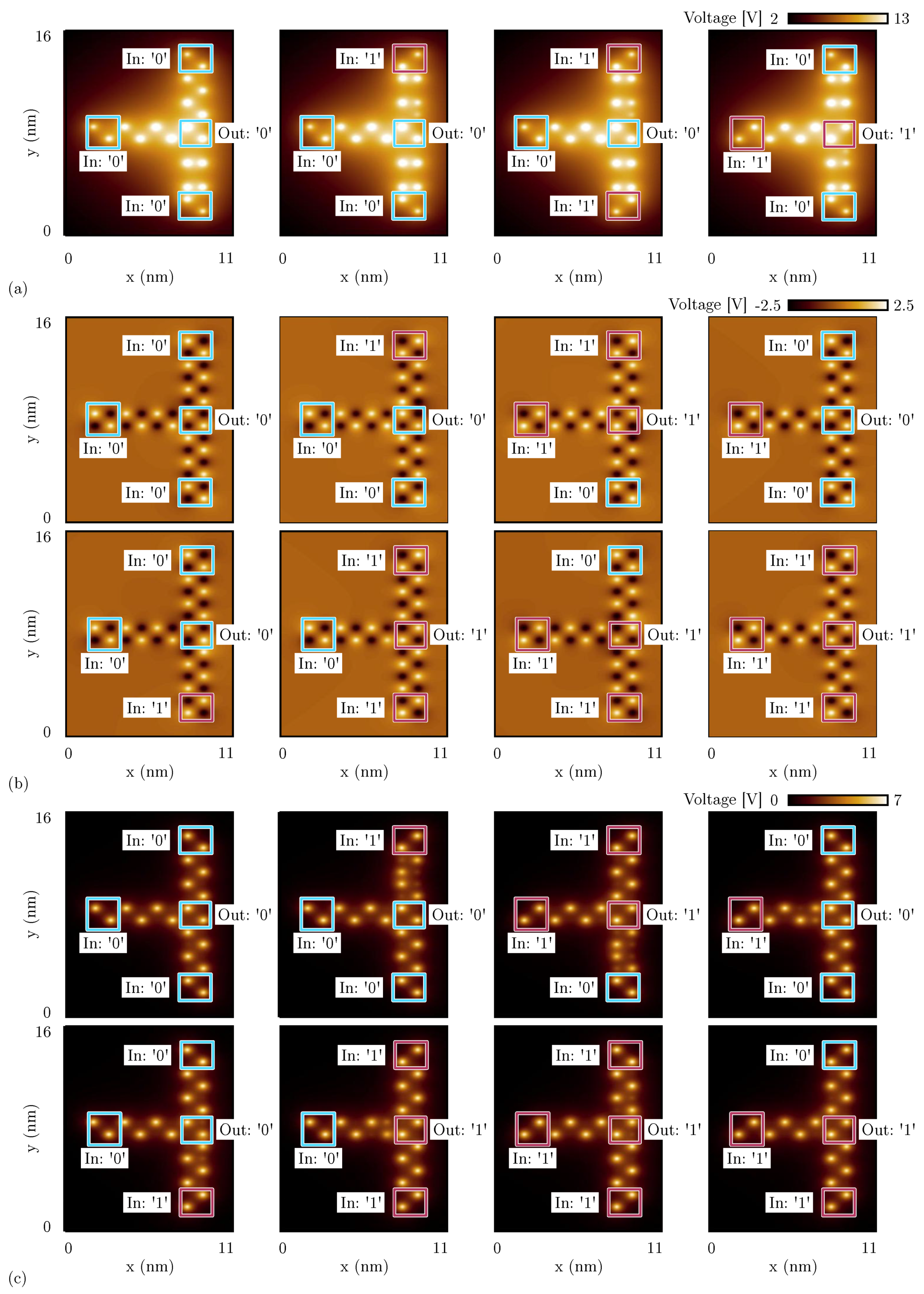
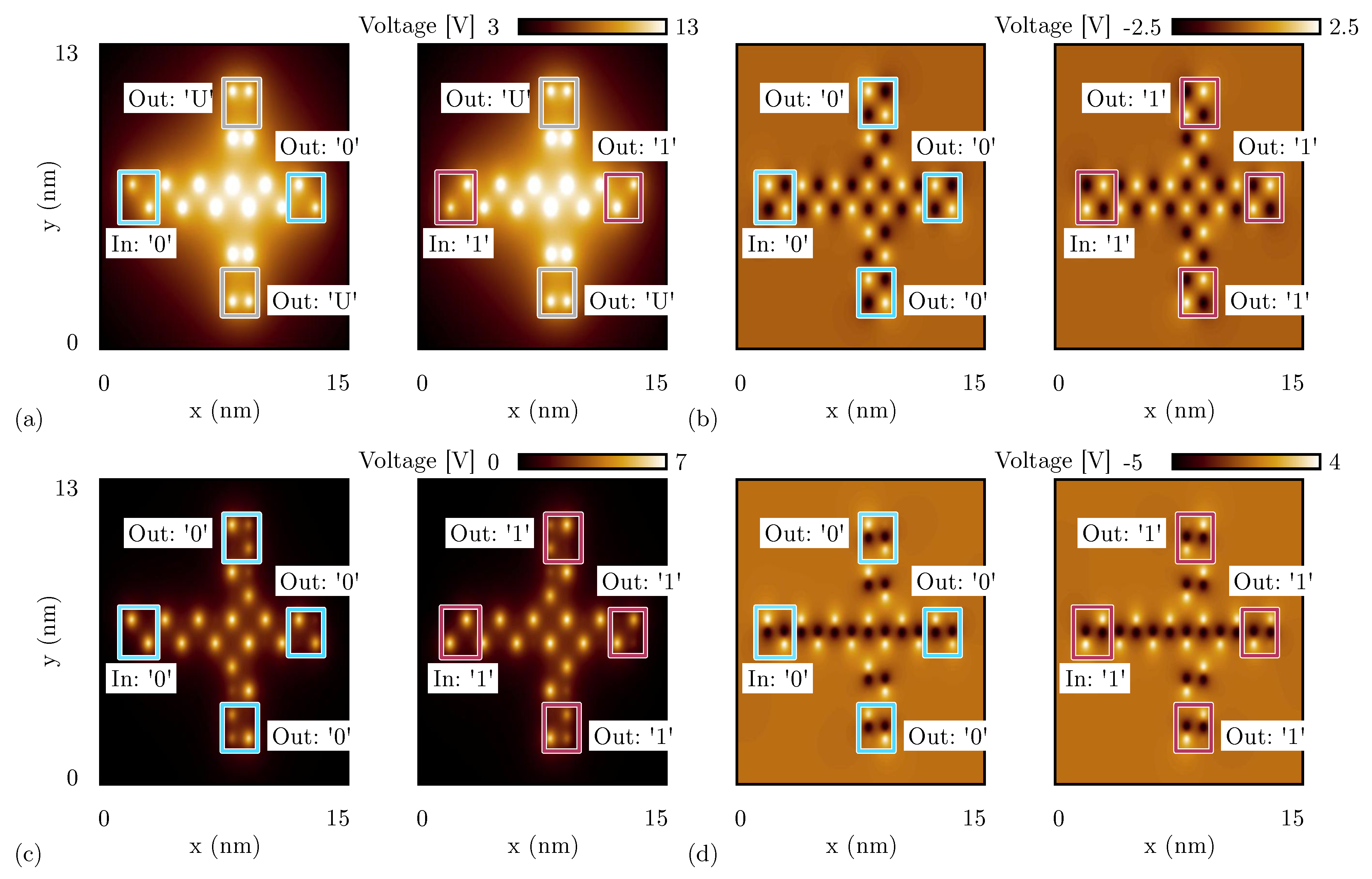
We analyze the MV using SCERPA for the three molecular species.
Figure 11a shows the potential distribution calculated 0.2 nm above the logic dot plane for four specific input configurations when oxidized molecules compose the device. The white spots indicate the aggregation of positive charges demonstrating the encoding of logic information in the molecular device. In the reported potential distribution, it is possible to notice the effect of the crosstalk field, which prevents the circuit from working correctly. Indeed, the left input always dominates onto the top and bottom inputs, as it can be seen from the third and fourth cases of
Figure 11a, where the output should match the logic information encoded on the vertical inputs. The cells connecting the vertical inputs present a charge configuration denoting both molecules having concordant dipole moments, as predicted by the energy analysis of
Section 4.1.
On the other hand,
Figure 11b shows the simulation performed with SCERPA of the MV implemented with neutral molecules. As expected, the system correctly works for all eight possible input configurations. Additionally, in the case of a MV implemented with zwitterionic molecules (counterion position is 10 Å from the logic dots), the device correctly works for all the input configurations, as can be evinced from
Figure 11c. Indeed, as already reported in
Section 5.1, the presence of the counterion reduces the crosstalk field, which is crucial for the correct functioning of the majority voter. Additionally, the simulations of
Figure 11c highlight another phenomenon of the molecular FCN technology, that is, the back-propagation effect. Indeed, in all the configurations with one input different from the others, the central cell back-influences the input wires encoding the opposite logic values.
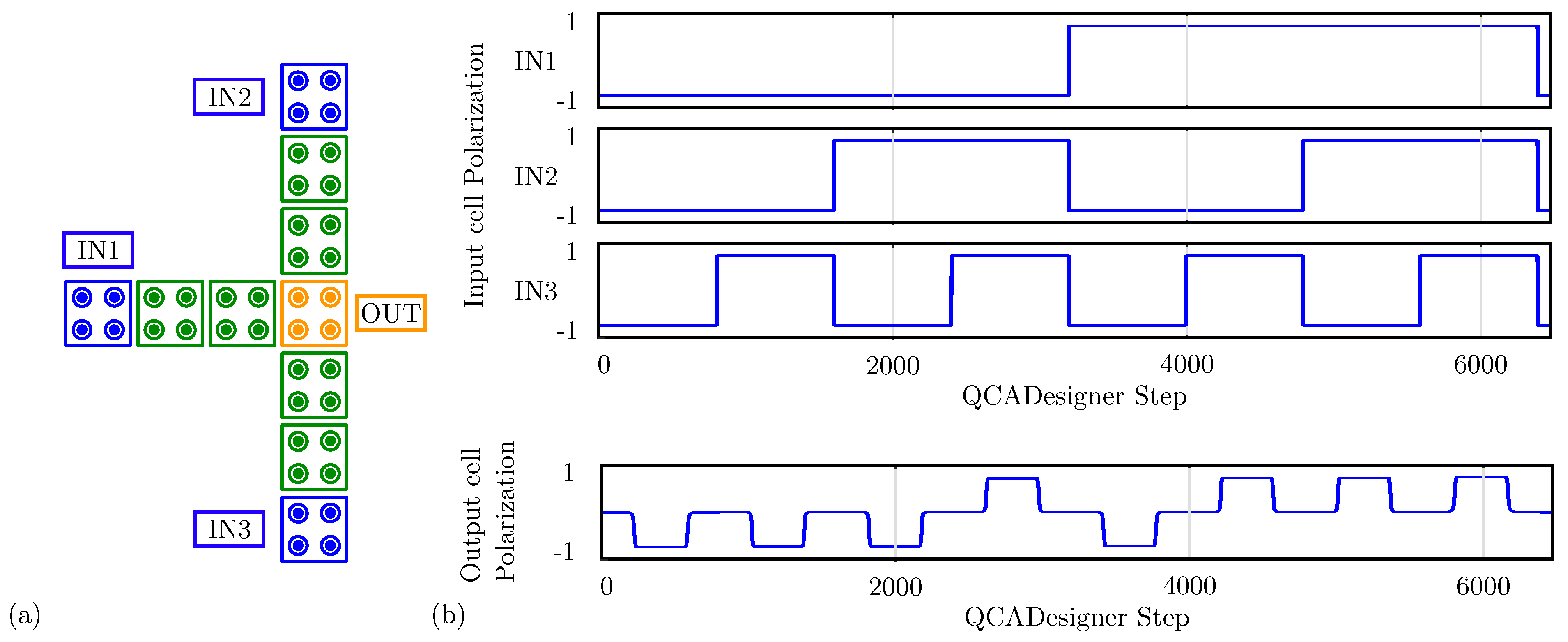
For comparison with the general QCA paradigm, we also simulate the MV using QCADesigner.
Figure 12a shows the layout of the device with inputs and output cells highlighted in blue and yellow, respectively, for the sake of clarity.
Figure 12b shows the waveform imposed on the three input cells and the polarization on the MV output cell versus the simulation step. The output is idle for the first half-period and assumes the correct logic state in the second half-period. Since the circuit is composed of a unique clock zone, there is no delay between input and output. The value of the output cell polarization at the end of each period is always consistent with the expectations. The values sampled at the end of each period associate with the configurations shown in
Figure 11b obtained through SCERPA for the device implemented with neutral molecules, reminding that a polarization
corresponds to a logic ‘0’, whereas a polarization
corresponds to a logic ‘1’. Indeed, QCADesigner assumes an interaction based on a single Kink Energy value and a neutral QCA cell, which is the case more similar to neutral molecular FCN. Moreover, analyzing the majority voter with zwitterionic and oxidized molecules, the effects to be mainly considered are related to the crosstalk field. However, the model of QCADesigner does not allow molecules of the same cell to switch independently, thus making the evaluation of the eventual crosstalk field impossible.
5.3. Fanout
Another device involving only adjacent interactions is the fanout circuit, a connection that replicates the information of the input wire on three output wires. Again, we simulate the circuit using SCERPA by considering all the molecular species.
Figure 13a shows the electrostatic potential evaluated 0.2 nm above the logic dots plane of the fanout circuit implemented with oxidized molecules. Analogously to the analysis reported in
Figure 11a, only the central output propagates the information correctly. Indeed, the vertical wires are influenced by the crosstalk field, leading to an undefined logic value for both the top and the bottom outputs cells, having the two molecules with concordant dipole moments.
On the contrary, if the circuit is implemented with neutral molecules, the crosstalk effect strongly reduces, thus the three outputs correctly replicate the information, see
Figure 13b.
Instead, the fanout circuit implemented with zwitterionic molecules does work correctly. Nevertheless, we observe different behavior depending on the position of the counterion.
Figure 13c shows the simulation result obtained with SCERPA when the counterion of the zwitterionic molecules is placed at 10 Å from the logic dots. The simulation confirms that the information is replicated on the three output wires. However, the information encoded on the two vertical wires is far from the ideal configuration. The output cells show a non-negligible charge distribution on three logic dots (i.e., three out of four logic dots composing the molecular cell), meaning that one of the two molecules is not fully polarized. Additionally, these border effects are mirrored depending on the input logic value and are a consequence of the influence of vertical interactions. This crosstalk effect is mitigated when the counterion is closer to the logic dots, as confirmed by the simulation results shown in
Figure 13d of the fanout circuit implemented with zwitterionic molecules with the counterion on the same plane of the logic dots. The negative charge is located on the
Dot 3, which is visible from the simulation as a black spot in the center of molecules.
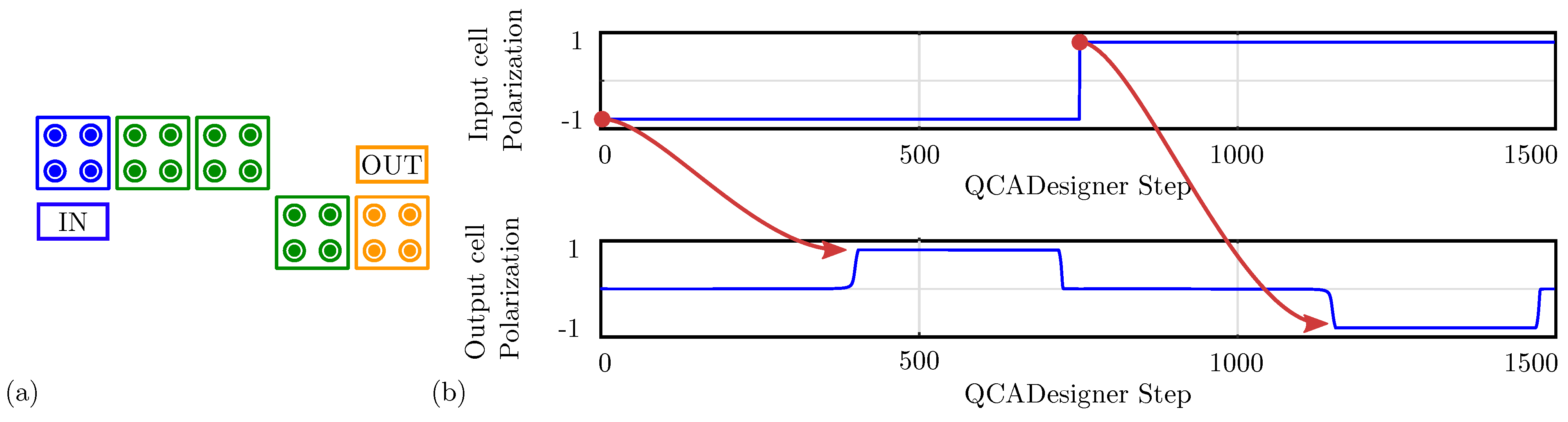
Finally, we simulate the fanout circuit with QCADesigner.
Figure 14a reports the used schematic with inputs and output cells highlighted in blue and yellow, respectively, for the sake of clarity.
Figure 14b shows the imposed input waveforms and the output cell polarization. The red arrows associate each logic input value with the corresponding output. For the sake of brevity, the figure reports the waveform of only one output cell. The not-shown cells are equal to the reported waveform output since the polarization on the three outputs is identical. The output cell polarization at the end of each period is always consistent with the expectations, therefore, the circuit correctly propagates the information. The values sampled at the end of each period associate with the configurations shown in
Figure 13b obtained through SCERPA for the device implemented with neutral molecules, remembering that a polarization
corresponds to a logic ‘0’, whereas a polarization
corresponds to a logic ‘1’.
5.4. Single-Branch Inverter
Another essential logic gate is the inverter, for which the literature proposes two layouts. At first, we analyze the single-branch layout, which is based on the single-diagonal interaction discussed in
Section 4.2.
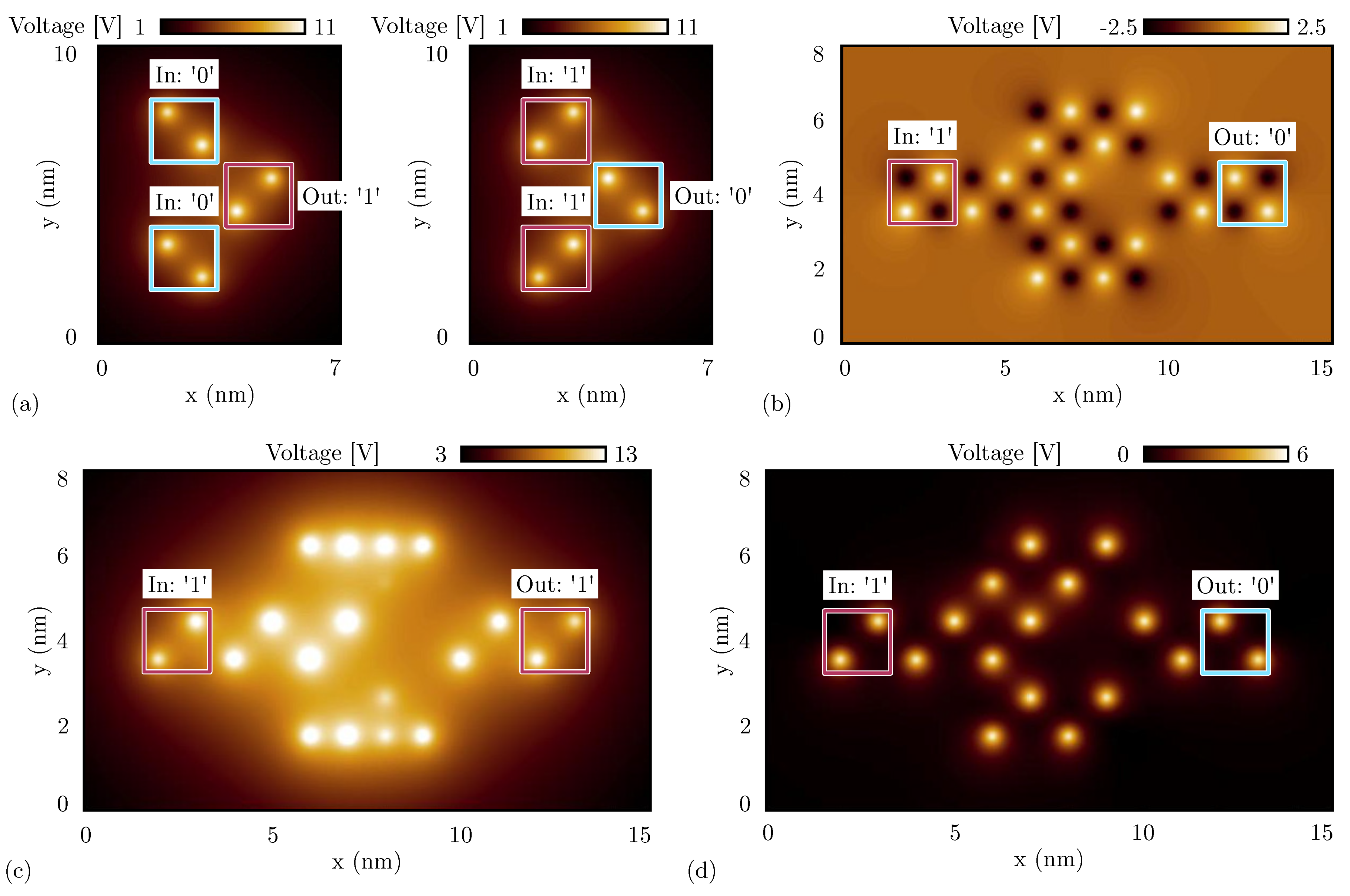
Figure 15a shows the electrostatic potential evaluated 0.2 nm above the logic dots obtained by the SCERPA simulation of a neutral single-branch inverter with logic input ‘1’, whereas
Figure 15b shows the simulation result with input logic ‘0’. As predicted by the energy analysis of the single diagonal interaction, the simulations with neutral molecules show the single-branch inverter correctly inverting both the input logic values. In fact, by concentrating on the two logic dots closest to the diagonal, the negative charge aggregation on the top wire (black spot) attracts the positive charge aggregation on the bottom wire (white spot) and vice versa, permitting the logic inversion.
Secondly, we simulate the single-branch inverter composed of oxidized molecules.
Figure 15c shows the SCERPA simulation of the device with logic input ‘1’, whereas
Figure 15d shows the simulation with input logic ‘0’. Even in this case, the simulation confirms the prediction of the energy analysis performed in
Section 4.2, where a unique minimum corresponding to the configuration ‘11’ was obtained. Indeed, the simulations show both the configurations outputting logic value ‘1’. This behavior is mainly due to the influence of the crosstalk field generated by the top and bottom wires, which is maximum in the case of oxidized molecules. The crosstalk effect is also evident from the charge configuration of the SCERPA simulations. By concentrating on the two logic dots closest to the diagonal in
Figure 15c, there are no negative charges that favor the output to invert the configuration. Being involved with only positive charges, the configuration with minimum energy is the one with the white spots (i.e., positive charges) as far away as possible.
Concerning zwitterionic molecules, the interaction depends on the counterion position as already discussed in
Section 4.2. Therefore, we validate the analysis of
Figure 8c by simulating with SCERPA the three significant cases reported in the plot.
Figure 15e shows the electrostatic potential evaluated 0.2 nm above the active dot plane of a single-branch inverter implemented with zwitterionic molecules when the counterion is on the same plane of the logic dots. The molecules behave similarly to neutral molecules, leading to correct inversion with both the inputs. In
Figure 15f, the counterion is located 5 Å below the active dot plane. In that case, the single-branch inverter still works correctly with both inputs. Finally,
Figure 15g shows the result obtained with the counterion placed 10 Å below the logic dots. The considered counterion distance is enough to obstacle the inverting behavior since the molecules behave more similar to the case of oxidized molecules, so the considerations regarding the simulation results are the same. Again, the behavior of the zwitterionic molecule is intermediate between the oxidized and the neutral molecule, and the position of the counterion plays a key role in establishing more similarity to one rather than the other.
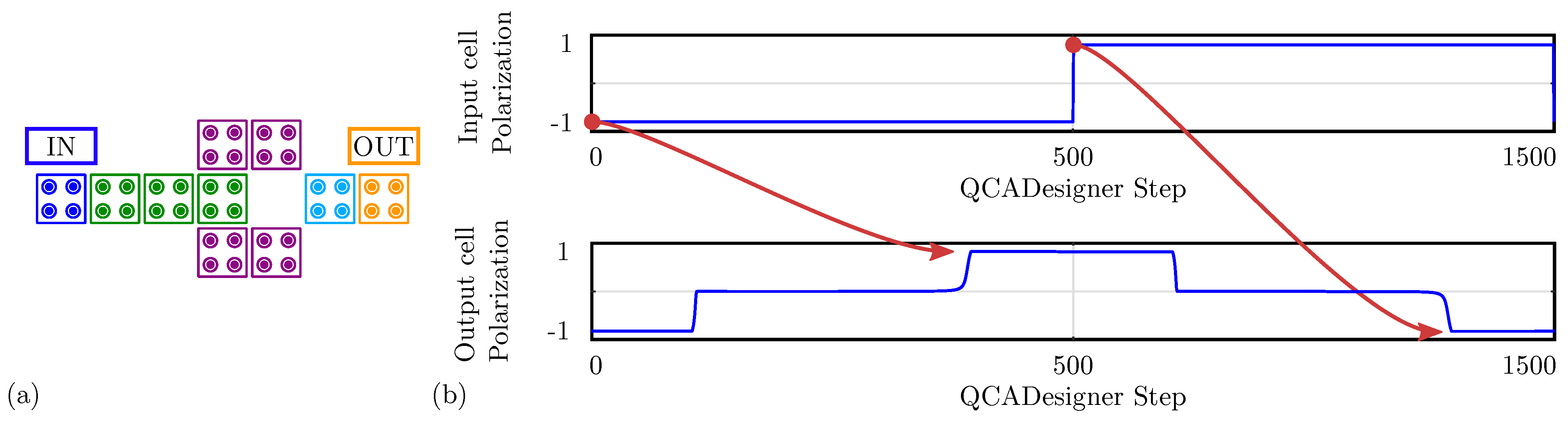
For comparison with the general QCA paradigm,
Figure 16a shows the schematic of a single-branch inverter drawn in QCADesigner with inputs and output cells highlighted in blue and yellow, respectively, for the sake of clarity.
Figure 16b shows the imposed input waveform and the output cell polarization obtained from the simulation: the red arrows associate each logic input value with the corresponding output. The results confirm the working principle of the single-branch inverter within the general QCA paradigm. The output cell polarization at the end of each period is always consistent with the expectations, therefore, the circuit correctly propagates the information. The values sampled at the end of each period associate with the configurations shown in
Figure 15a obtained through SCERPA for the device implemented with neutral molecules, remembering that a polarization
corresponds to a logic ‘0’, whereas a polarization
corresponds to a logic ‘1’. The QCADesigner tool gives consistent results with the case of neutral molecules. Indeed, QCADesigner assumes an interaction based on a single Kink Energy value and a neutral QCA cell, which is the case more similar to neutral molecular FCN. The model used to describe the QCA cell does not allow the designer to simulate molecular circuits composed of oxidized or any zwitterionic molecules.
5.5. Double-Branch Inverter
As reported in
Section 5.4, a single-branch inverter layout may not be sufficient to guarantee the correct inversion operation since the behavior of the single diagonal cell-to-cell interaction depends on the input configuration and the molecular species. Instead, as discussed in
Section 4.3, double diagonal interactions improve the symmetry of the interactions, eventually favoring the inversion mechanism.
We first concentrate on the simulation of the double diagonal interaction by exploiting the schematic already shown in
Figure 6d. For the sake of brevity, we analyze the case with oxidized molecules only since the oxidized species is the most critical one concerning the diagonal interaction.
Figure 17a shows the potential evaluated 0.2 nm above the logic dot plane calculated with SCERPA for both the possible inputs. The logic encoded by the two driver cells is kept equal to emulate the behavior of the actual device, whereas the polarization of the output cell is obtained with the SCERPA tool. The schematic correctly works for both the logic values, confirming the expectation predicted by the energy analysis.
We now simulate the entire double-branch inverter. For the sake of brevity, we report only the case with input logic ‘1’, which is the most critical configuration, as reported in
Section 5.4. We demonstrate in
Section 5.4 that for neutral molecules and well-engineered zwitterionic molecules, one branch is sufficient to invert the information correctly thanks to the presence of both positive and negative charges. Therefore, a double-branch inverter is expected to also work for neutral molecules.
Figure 17b shows the result of the SCERPA simulation of the double branch inverter implemented with neutral molecules with a logic ‘1’ input. The result confirms the capability of the considered layout to perform the inversion operation with neutral species.
Secondly, we simulate the same circuit made of oxidized molecules, which is the most crucial species concerning the inversion operation.
Figure 17c shows the electrostatic potential of the SCERPA simulation for the configuration with a logic ‘1’ input. As the simulation demonstrates, even if the inversion mechanism works, Crosstalk Field clearly obstacles the inversion, making difficult the propagation of the information on the two branches. Indeed, the charge of molecules composing the two branches is located on the lateral dots of branch molecules, maximizing the distance between the positive charges and the center of the inverter. Regarding the crosstalk analysis performed in
Section 5.1, the center–center distance between the two inverter wires is 2 nm. According to
Figure 10b, the crosstalk field generated by a wire with distance
nm is about 1.562 V/nm, which is a value comparable with typical fields permitting the polarization of molecules in FCN devices, thus justifying the incorrect polarization of molecules on the two branches.
Finally, we analyze the double-branch inverter made of zwitterionic molecules. In particular, we concentrate on the molecule geometry with the counterion placed at 10 Å from the logic dots, which makes the molecule sufficiently similar to oxidized molecules, impinging on the behavior of a single-branch inverter, as demonstrated in
Section 5.4.
Figure 17d shows the SCERPA simulation for the case with input logic ‘1’, demonstrating its correct behavior. As anticipated with the energy analysis, the double-branch inverter structure reduces the asymmetry typical of the single-branch inverter, favoring the inversion operation.
For the sake of completeness,
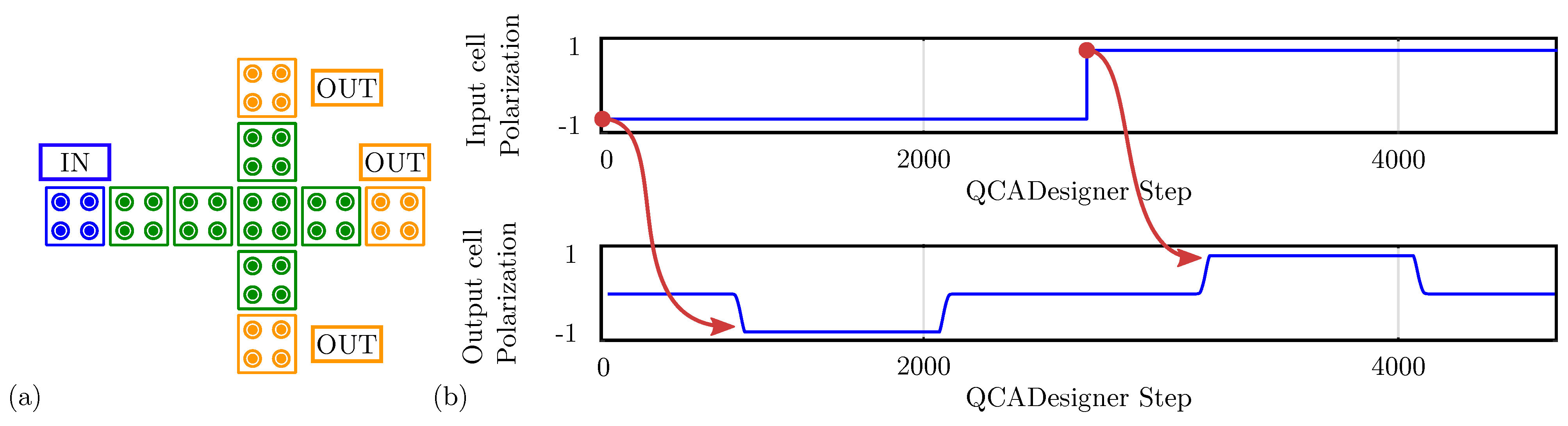
Figure 18a shows the schematic of a double-branch inverter drawn in QCADesigner with inputs and output cells highlighted in blue and yellow, respectively, for the sake of clarity. Different clock zones are highlighted with different cell colors.
Figure 18b shows the imposed input waveform and the output cell polarization obtained from the simulation: the red arrows associate each logic input value with the corresponding output. Since the circuit comprises three clock zones, there is a delay between input and output switching. The output cell polarization at the end of each period is always consistent with the expectations, therefore, the circuit correctly propagates the information. The values sampled at the end of each period associate with the configurations shown in
Figure 17b obtained through SCERPA for the device implemented with neutral molecules, remembering that a polarization
corresponds to a logic ‘0’, whereas a polarization
corresponds to a logic ‘1’. The results confirm the working principle of the double-branch inverter within the general QCA paradigm. This result further confirms that QCADesigner does not allow the designer to simulate molecular circuits considering the oxidized or zwitterionic nature of the molecule.
In conclusion, the double-branch configuration generally favors the inversion of the information. Both neutral and well-engineered zwitterionic species can be used to build this device. In contrast, the crosstalk effect obstructs the possibility to perform the inversion also with the double-branch inverter.
6. Conclusions
This work clarifies and categorizes the different possible molecular FCN implementations, comparing them to the generic Quantum-dot Cellular Automata (QCA). Furthermore, we highlight how the electrostatic characteristics of molecules influence the functional behavior of FCN circuits. In particular, this work discusses three molecular species: neutral, oxidized, and zwitterionic molecules.
From the presented analysis, the neutral molecule shows the lowest crosstalk effect and simplifies the inversion, which can be achieved with a single diagonal interaction. Nevertheless, the neutral molecule presents no net positive charge on the logical dots, which is a problem from the reset perspective since the NULL configuration cannot be obtained with a negative clock field pushing the positive charge on a possible third dot. Therefore, the neutral molecule should be reset by modifying its switching characteristics.
The clocking capability is simplified for the oxidized molecules since an external electric field can move the net positive charge in an eventual third dot. Nevertheless, the oxidized molecules present the worst crosstalk effects, which obstruct the design of even simple circuits. The counterion is required to guarantee the neutrality of the molecule and reduce crosstalk effects. In addition, the highly repulsive characteristics of the oxidized molecular cell make the inversion challenging and not practicable with a single diagonal interaction. This work demonstrates the impossibility of using the single-branch inverter for oxidized molecules. Moreover, the single-branch inverter cannot be used according to the ideal definition of the general QCA, considered a cell with two electrons (i.e., two negative repelling charges) with no counterion making the cell neutral.
Finally, the zwitterionic molecules show an intermediated behavior between the two mentioned molecules. The positive net charge on the logic dots enables the reset of the molecular cell by applying a negative clock field, and the neutrality of the molecule reduces the crosstalk. It is essential to notice that the position of the counterion influences the device behavior. The zwitterionic molecule imitates the neutral molecule when the counterion is close to the logical dots, whereas it is similar to oxidized molecules when the counterion is far away. It is worth mentioning that the zwitterionic molecule, as considered in this paper, behaves similarly to oxidized molecules with the counterion. However, the two molecular species should not be confused since the zwitterionic molecule counterion is fixed within the molecule geometry.
This work guides chemists to synthesize correct molecules and improve the ability of electronics engineers to design circuits with physical awareness of the molecule. We highlight the advantages of using zwitterionic molecules, yet, we stress that this molecule should be carefully simulated with tools that consider its electrostatic behavior and that the position of the counterion in the molecule is particularly significant. The final behavior of molecular FCN circuits cannot be evaluated by ignoring the effective behavior of the molecule, and the simulation tool used for the design must take the effective molecular characteristics into account.
Concerning the tools, we demonstrate the generality of the SCERPA algorithm, which considers the molecule effective behavior and can be used to analyze the three molecular species. The obtained results on the three molecular species are consistent with energy analysis. The results also motivate further research on the SCERPA development to integrate it into design tools, eventually adding dynamic molecular models. On the contrary, QCADesigner provides a GUI and implements dynamic calculation, even though it is based on the general two-state approximation and does not explicitly consider the specific molecular physics. Nevertheless, the scope of QCADesigner is limited to analyzing neutral molecules, making it challenging to analyze molecular FCN devices entirely and reliably. Indeed, QCADesigner can be used to analyze the functional behavior of general QCA circuits, yet a validation with a second tool (e.g., SCERPA) is mandatory. Indeed, neglecting the molecular species in the simulation, thus assuming the molecular cells perfectly fit the general QCA paradigm, leads to questionable molecular circuits and slows down the assessment of molecular FCN as a possible candidate for future digital electronics.


 ,
, 


