Article

Optimal Operation of a Microgrid with Hydrogen Storage Based on Deep Reinforcement Learning

1
College of Electrical Engineering and Automation, Fuzhou University, Fuzhou 350108, China
2
Fujian Province University Engineering Research Center of Smart Distribution Grid Equipment, Fuzhou 350108, China
3
Fujian Key Laboratory of New Energy Generation and Power Conversion, Fuzhou 350108, China
*
Author to whom correspondence should be addressed.
Electronics 2022, 11(2), 196; https://doi.org/10.3390/electronics11020196
Submission received: 10 December 2021 / Revised: 5 January 2022 / Accepted: 6 January 2022 / Published: 9 January 2022
(This article belongs to the Section Artificial Intelligence)

Abstract

:
Microgrid with hydrogen storage is an effective way to integrate renewable energy and reduce carbon emissions. This paper proposes an optimal operation method for a microgrid with hydrogen storage. The electrolyzer efficiency characteristic model is established based on the linear interpolation method. The optimal operation model of microgrid is incorporated with the electrolyzer efficiency characteristic model. The sequential decision-making problem of the optimal operation of microgrid is solved by a deep deterministic policy gradient algorithm. Simulation results show that the proposed method can reduce about 5% of the operation cost of the microgrid compared with traditional algorithms and has a certain generalization capability.

1. Introduction

Renewable energy, such as wind and solar energy, is essential for the energy decarbonization [1]. Microgrid is an important form for renewable energy integration to the power systems [2]. Hydrogen energy is another type of clean and low-carbon energy. The combustion product of hydrogen is water with zero-carbon emissions [3]. For microgrid systems with high renewable energy integration, hydrogen energy can be used as a long-term energy storage to improve the utilization of renewable energy and reduce carbon emissions. The renewable energy is intermittent and random, and brings great challenges to the operation of the microgrids [4].
To address the economic dispatch problem in microgrids containing hydrogen storage, a mixed integer nonlinear dispatch model for a microgrid with 100% renewable energy generation is proposed in [5], and the GAMS solver is used to optimize the operation strategy of hydrogen storage and improve the economic efficiency of the microgrid in the day-ahead market. In [6], a nonlinear scheduling model for a microgrid containing fuel cell and hydrogen storage systems is proposed and the CONOPT solver is used to optimize the energy purchase cost of the microgrid. In [7], an optimization model to schedule an islanded microgrid with various resources, including photovoltaic generation and hydrogen energy system, is proposed. The problem is represented as a mixed integer linear program problem and solved by CPLEX. In [8], the retail price problem of the electricity energy retailer that owns plug-in electric vehicles and hydrogen storage systems is proposed. The proposed model is verified by simulation using GAMS. In [9], the harmony search algorithm is used to optimize the hydrogen production capacity of the hydrogen storage in the microgrid to reduce the operating cost. In [10], a hybrid AC-DC microgrid model containing electric vehicles and hydrogen fuel cells is presented, and the operating scheme is optimized using an improved teacher learning algorithm. In [11], the genetic algorithm is used to optimize the life cycle cost of the microgrid containing hybrid electric-hydrogen energy storage. In [12], the particle swarm algorithm is used to solve the multi-objective energy management problem of renewable energy microgrid containing electric-hydrogen hybrid energy storage to improve the system efficiency.
The conventional mathematical programing algorithms in the above literature are computationally efficient. However, these methods tend to be trapped in local optima when the problem is nonlinear and nonconvex. The heuristic algorithms have better global optimization capability, but suffer from slow convergence and poor generalization. In addition, the above literature mainly focuses on the day-ahead scheduling problem of microgrid, and relies on the accurate predictions of renewable energy and load.
Deep reinforcement learning is a machine learning method with the ability to perceive the environment and address uncertainties. Currently, deep reinforcement learning has been used to achieve certain results in several areas, such as reactive power optimization [13,14], electric vehicles [15,16], and power markets [17,18]. In terms of optimal operation, the deep reinforcement learning algorithms is used in [19] to solve the energy management problem of residential energy system with electricity, heat, and gas demand. In [20], a microgrid scheduling model is proposed and deep reinforcement learning algorithms is adopted to reduce the power purchase cost. However, this literature fail to consider the impact of hydrogen energy storage system on the microgrid operation. In [21], a coordinated control method for electrochemical and hydrogen energy storage in microgrid based on deep reinforcement learning is proposed. However, the hydrogen storage model is simple and ignores the electrolyzer efficiency characteristics, which has significant influence on the operation of microgrid. Moreover, only sub-optimal solution can be found because of the discretization of the action space.
In this paper, an optimal operation model for a microgrid with hydrogen energy storage system is developed. The efficiency-power model of the electrolyzer is established based on linear interpolation to evaluate the operating cost of the electrolyzer. The objective of the optimal operation model is to reduce the operation cost and guarantee the safety of the system. The deep deterministic policy gradient (DDPG) algorithm is used to optimize the operation scheme of the microgrid. The DDPG algorithm can deal with the continuous action space problem and obtains better operation scheme compared with the conventional algorithms. Additionally, the trained DDPG model is used in new scenarios. The simulation results show that the DDPG algorithm has generalization capabilities.
The main contributions can be summarized as:
  • A refined model represents the electrolyzer efficiency characteristics based on the linear interpolation method is proposed;
  • An optimal operation model for a microgrid with hydrogen storage is proposed. The electrolyzer efficiency characteristics model is incorporated into the optimal operation model;
  • The DDPG algorithm is adopted to solve the optimal operation model, which has a continuous action space.

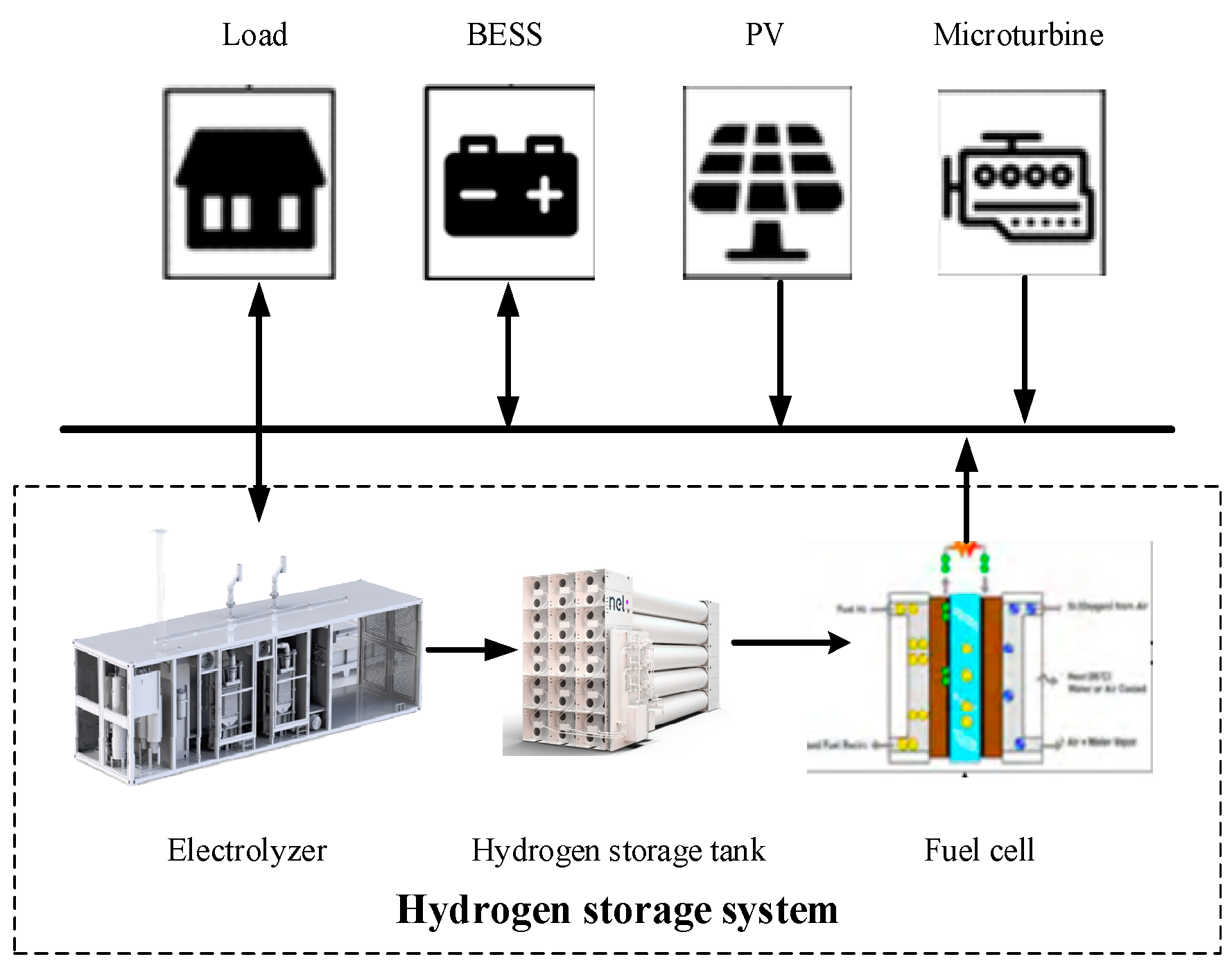
2. Model of the Microgrid System

A microgrid can increase the integration of renewable energy and reduce the carbon emissions of the whole energy system. In this paper, an islanded microgrid was constructed. The structure of the microgrid is shown in Figure 1. The microgrid included the load, a microturbine, a photovoltaic (PV) generation device, a battery energy storage system (BESS), and a hydrogen storage system. The hydrogen storage system consisted of an electrolyzer, a hydrogen storage tank, and a solid oxide fuel cell (SOFC). The hydrogen storage system [22] can provide regulation capability to the microgrid and improve the system reliability.

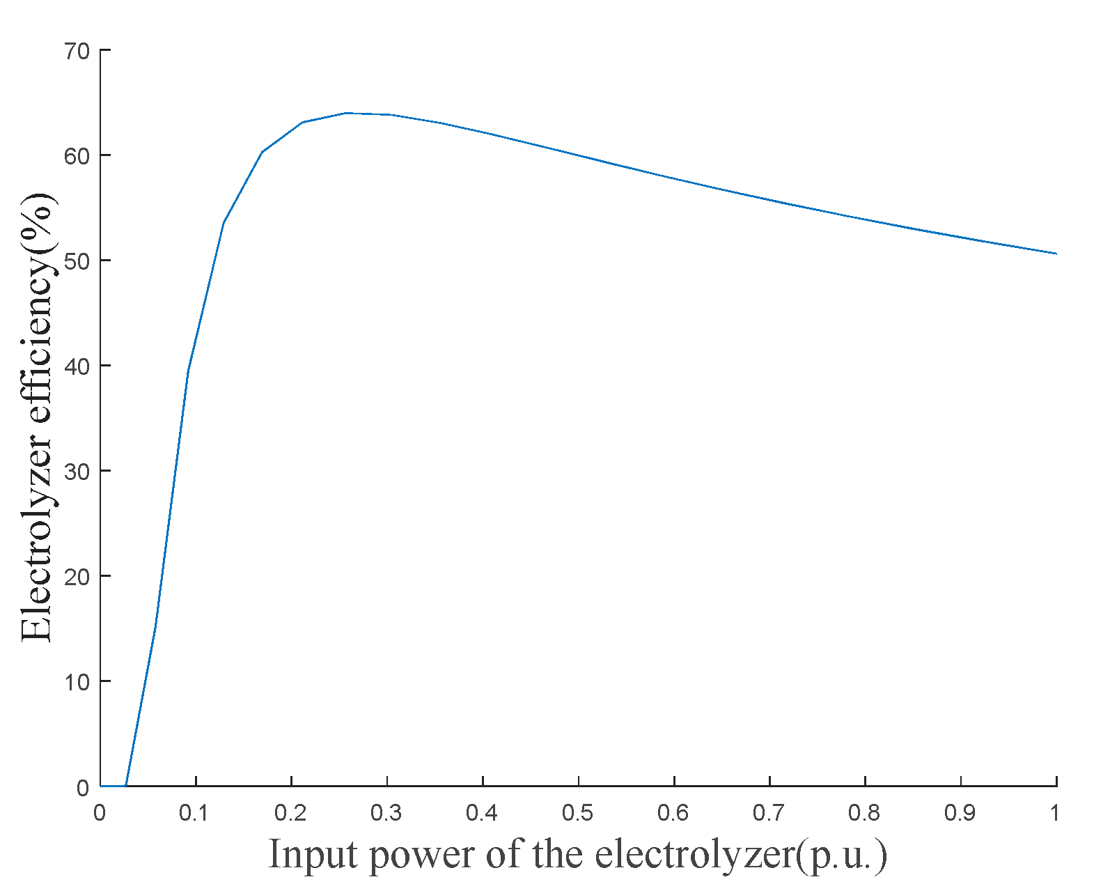
2.1. Electrolyzer Efficiency

Electrolyzer efficiency η e l is the efficiency of the hydrolysis reaction at constant temperature and pressure. The electrolyzer efficiency [23] consists of voltage efficiency η v and current efficiency η i as below:
η e l = η i η v
The current efficiency, also known as Faraday efficiency, can be expressed as:
η i = 96 . 5 e 0.09 / I 75.5 / I 2
where I is the stack current of the electrolyzer.
Voltage efficiency is the ratio between the theoretical decomposition voltage of water and the actual decomposition voltage, which can be expressed as
η v = ( U t n / U e l ) 100 %
where U t n is the theoretical decomposition voltage, which is generally 1.482 V; U e l is the actual decomposition voltage. Under the pressure p of 1.01 × 10⁵ Pa, U e l depends on the unit current density during the electrolysis of water, as below:
U e l ( j , T , p ) = U r e v ( T , p ) + U o h m + U h 2 ( j , T ) + U o 2 ( j , T )
where j is the unit current density; T is the working temperature of the electrolyzer; U r e v is the reversible voltage of the electrolytic water; U o h m is the voltage drop caused by the resistance of electrolyte; U h 2 and U o 2 are the hydrogen overpotential and oxygen overpotential generated by the electrolytic water, respectively. U r e v , U o h m , U h 2 and U o 2 are determined by
U r e v ( T , p ) = 1.5184 1.5421 × 10 3 T + 9.523 × 10 5 T ln T + 9.84 × 10 8 T 2
U o h m = I R i
U h 2 ( j , T ) = R T α c n c F ln ( j j c o )
U o 2 ( j , T ) = R T α a n a F ln ( j j a o )
where R i is the resistance of the electrolyte; R is the universal gas constant, F is the Faraday constant; α a and α c are the charge transfer coefficients of anode and cathode, respectively; j a o and j c o are the exchange current densities of anode and cathode, respectively; n a and n c are the electron transfer numbers of anode and cathode, respectively. The input power of the electrolyzer P e l is related to the electrolyzer current I as follows
P e l = U e l I
The relation between the input power and the electrolyzer efficiency can be obtained by Equations (1)–(9). However, the relation is complicated and contains logarithmic calculations. Thus, it is difficult to find the corresponding electrolyzer efficiency based on the input power of the electrolyzer in the microgrid scheduling problem.
In order to simplify the electrolyzer efficiency characteristics model, this paper firstly obtained η e l and the corresponding P e l according to j. Then, the electrolyzer efficiency characteristic curve was obtained based on η e l and P e l , as shown in Figure 2. Twenty points on the efficiency characteristic curve were taken as the original data to form the data table. When solving the scheduling problem, the electrolytic cell efficiency corresponding to P e l can be quickly found by looking up the table and linear interpolation, as shown below:
η e l = η 1 η 0 P 1 P 0 ( P e l P 0 ) + η 0
where P 0 and P 1 are the two power values nearest to P e l in the data table; η 0 and η 1 are the corresponding electrolyzer efficiencies of P 0 and P 1 in the data table.
When the input power and the efficiency of the electrolyzer are determined, the hydrogen production power of the electrolyzer can be calculated according to Equation (11):
P e l , o u t = η e l P e l
where P e l , o u t is the hydrogen production power of the electrolyzer.
Different from the conventional fixed efficiency model of electrolyzer, the hydrogen production power was obtained by multiplying the power consumption of electrolyzer and the respective efficiency obtained from the electrolyzer efficiency characteristic model.

2.2. Economic Dispatch Model of Microgrid

2.2.1. Objective Function

The total cost F in all scheduling periods of a day is set as the objective function. This objective function not only covers the economic benefits of microgrid, but also takes into account the environmental benefits of microgrid, as below:
F = t = 1 T ( C M T ( t ) + C c o 2 M T ( t ) + C b a t ( t ) + C e l ( t ) + C f c ( t ) )
where T is the whole dispatching cycle; t is the time step, and the scheduling interval is 1 h; C M T ( t ) is the operating cost of the microturbine at time t; C c o 2 M T ( t ) is the CO2 emission cost of the microturbine at time t; C b a t ( t ) , C e l ( t ) and C f c ( t ) are the operation costs of the BESS, electrolyzer, and fuel cell, respectively. The above operation costs can be determined by
C M T ( t ) = δ 2 ( P t M T ) 2 + δ 1 P t M T + δ 0
C c o 2 M T ( t ) = c c o 2 λ c o 2 M T P t M T
C b a t ( t ) = c b a t | P t b | Δ t
C e l ( t ) = c e l P t e l Δ t
C f c ( t ) = c f c P t f c Δ t
where δ 2 , δ 1 , and δ 0 are the power generation cost coefficients of microturbine; Δ t is the scheduling interval; c b a t , c e l , and c f c are the operation and maintenance cost coefficients of BESS, electrolyzer, and fuel cell, respectively; λ c o 2 M T is the CO2 emission coefficient of microturbine; c c o 2 is the carbon emission price of carbon trading market; P t M T is the power generation of microturbine at time t; P t b is the charging or discharging power of BESS at time t, and a positive value of P t b means the BESS is charged. Otherwise, BESS is discharged; P t e l and P t f c are the input power of electrolyzer and output power of fuel cell at time t, respectively.

2.2.2. Constraints

Generally, in order to ensure the overall working efficiency of the hydrogen storage system, the electrolyzer and fuel cell cannot work at the same time. Therefore, the input power of the electrolyzer is regarded as the charging power of the whole hydrogen storage system, and the discharging power of the fuel cell is regarded as the discharging power of the whole hydrogen storage system, as below:
P t h 2 = { P t e l P t h 2 0 P t f c P t h 2 < 0
where P t h 2 is the charging/discharging power of the hydrogen storage system at time t, and a positive value of P t h 2 means the hydrogen storage system is charged. Otherwise, the hydrogen storage system is discharged.
In addition to economic efficiency, the operation safety of microgrid also needs to be guaranteed. The operation constraints of microgrid are as follows:
  • Power balance
The microgrid in this study is off grid. The power balance of the microgrid mainly relies on the output power of PV generation and microturbine. The imbalance power is regulated by BESS and hydrogen storage system. The power balance equation is
P t P V P t c u r t + P t M T = P t l o a d P t l o s s + P t b + P t h 2
where P t P V , P t c u r t , P t l o a d and P t l o s s are the available PV generation, curtailment of PV generation, load power, and curtailment of load at time t, respectively.
2.
Operating power constraints
To ensure the safety of the devices in microgrid, the operating power constraints are as below:
P min M T P t M T P max M T
P min b P t b P max b
P min e l P t e l P max e l
P min f c P t f c P max f c
where P max M T , P max b , P max e l and P max f c are the upper power limits of microturbine, BESS, electrolyzer, and fuel cell, respectively; P min M T , P min b , P min e l and P min f c are the lower power limits of microturbine, BESS, electrolyzer, and fuel cell, respectively.
3.
Energy storage capacity
In order to avoid overcharging and over-discharging of energy storage, the states of charge (SOCs) of energy storage can be constrained as:
S O C min b S t b S O C max b
S O C min h 2 S t h 2 S O C max h 2
where S t b is the SOC of BESS at time t; S O C max b and S O C min b are the upper and lower limits of SOC of BESS, respectively; S t h 2 is the SOC of hydrogen storage system at time t; S O C max h 2 and S O C min h 2 are the upper and lower limits of the SOC of hydrogen storage system.
The SOCs of the two energy storage devices can be calculated by the following equations:
S t b = { S t 1 b + P t b η b Δ t E b P t b 0 S t 1 b + P t b Δ t ζ b E b P t b < 0
S t h 2 = { S t 1 h 2 + P t h 2 η h 2 Δ t E h 2 P t h 2 0 S t 1 h 2 + P t h 2 Δ t ς h 2 E h 2 P t h 2 < 0
where η b and ζ b are the charging and discharging efficiencies of BESS, respectively; η h 2 and ς h 2 are the efficiencies of electrolyzer and fuel cell, respectively; E b and E h 2 are the capacities of BESS and hydrogen storage tank, respectively.
Because the operating cost of microturbine is a quadratic function, the objective function is nonlinear. All of the constraints are linear. Thus, the whole model is a quadratic programing model that is nonlinear.

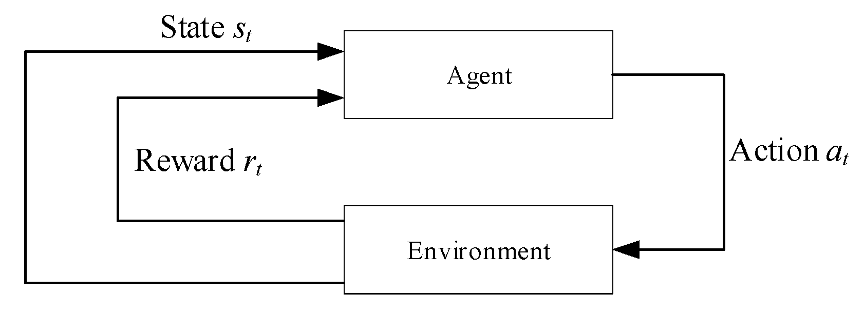
3. Deep Reinforcement Learning

Deep reinforcement learning is a data-driven method and can be used in high-dimensional sequential decision-making problem. The deep reinforcement learning model can be trained offline and applied online [24]. Thus, deep reinforcement learning is suitable for the application of the optimal operation of the microgrid. The block diagram of optimal operation of microgrid with deep reinforcement learning is shown in Figure 3.

3.1. Reinforcement Learning

Reinforcement learning is the learning process where an intelligence agent interacts with the environment in order to maximize the cumulative reward. The schematic diagram of reinforcement learning is shown in Figure 4.
Q-learning is one of the main algorithms of reinforcement learning. Q-learning evaluates the merit of an action by the state action value function and obtains the optimal policy by solving the optimal action value function. The action value function is calculated as below:
Q k + 1 ( s t , a t ) = Q k ( s t , a t ) + α [ r k + γ max a Q k ( s t + 1 , a ) Q k ( s t , a t ) ]
where Q k ( s t , a t ) is the value function of the state action at the kth iteration under the state s t ; γ is the decay rate; r k is the reward value under the action a t at the kth iteration; a is the arbitrary action that can be selected for the state s t + 1 .

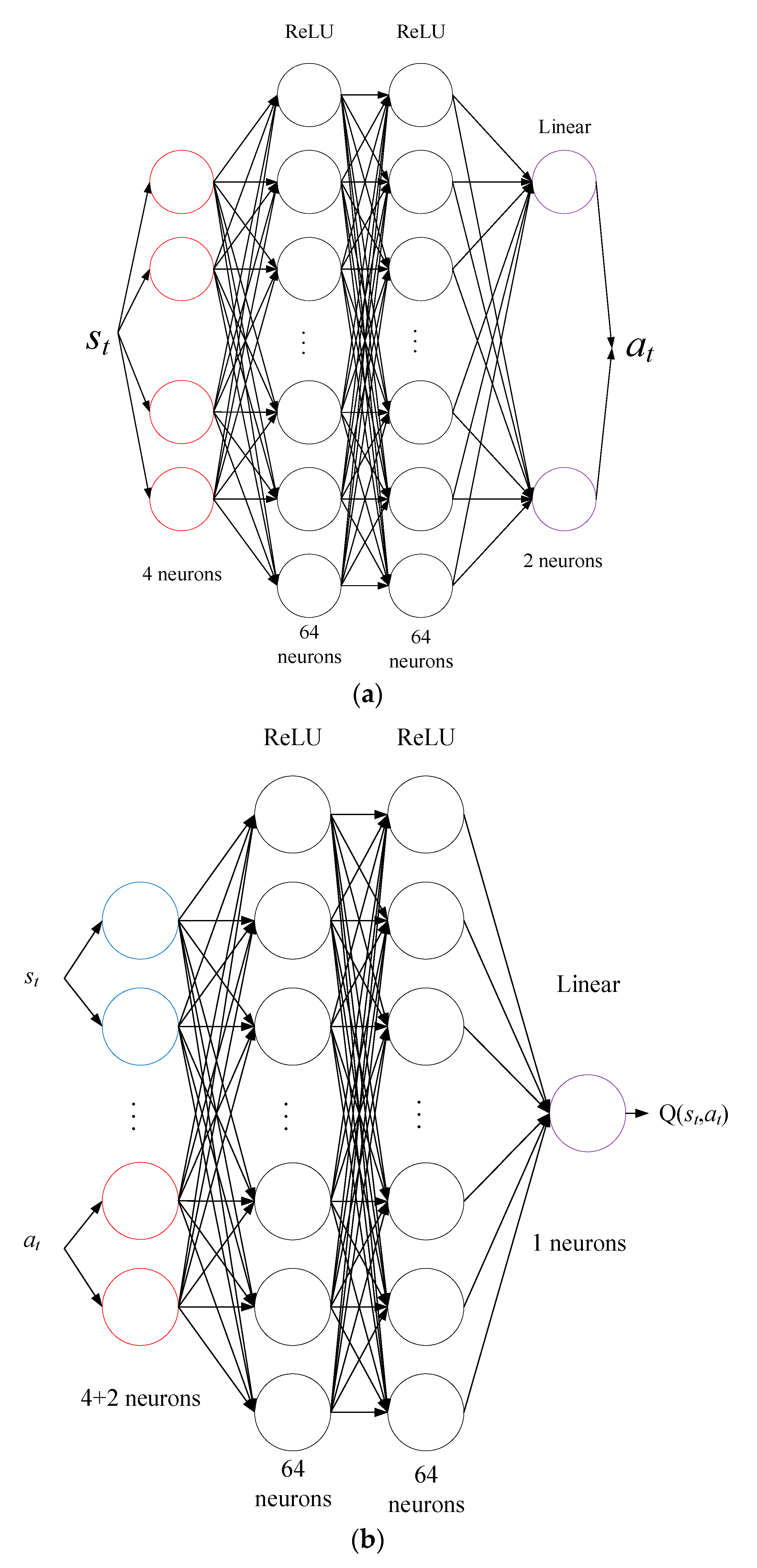
3.2. Deep Deterministic Policy Gradient Algorithm

Conventional reinforcement learning methods, such as Q-learning, perform well in problems with small discrete spaces. However, when dealing with continuous state variable tasks, the number of states using discretization method increases exponentially as the dimensionality of the space increases. This results in the curse of dimensionality. With the development of machine learning, deep learning is combined with reinforcement learning to solve the curse of dimensionality problem. In this paper, the DDPG algorithm was used to solve the microgrid optimal operation problem. The DDPG algorithm [20] consists of two independent neural networks fitting the policy function and the action-value function. The two neural networks are called the policy network and the evaluation network.
In addition, two target networks were used for the policy network and evaluation network to add stability to training. The network parameters of the strategy network, evaluation network, target strategy network, and target evaluation network are θ π , θ Q , θ π and θ Q , respectively. The strategy network and the evaluation network were updated with the corresponding learning rates for the parameters. The evaluation network was updated by minimizing the loss function as below:
L ( θ Q ) = E ( y t Q ( s t , a t | θ Q ) ) 2
y t = r t + γ Q ( s t + 1 , π ( s t + 1 | θ π ) | θ Q )
where E is expectation; y t is target Q value; Q and π are target Q value and target strategy, respectively.
The policy network parameters were updated by sampling the policy gradient as:
θ π π = a Q ( s , a | θ Q ) | s = s t , a = π ( s t ) θ π π ( s | θ π ) | s = s t
After the parameters of the strategy network and evaluation network were updated, the parameters of the two target networks were updated through soft update technique as below:
θ Q = τ θ Q + ( 1 τ ) θ Q
θ π = τ θ π + ( 1 - τ ) θ π
where τ is the soft update co-efficient.
In order to enhance the ability to explore the environment, random noise υ t needs to be added to the actions as:
a t = π ( s t | θ π ) + υ t

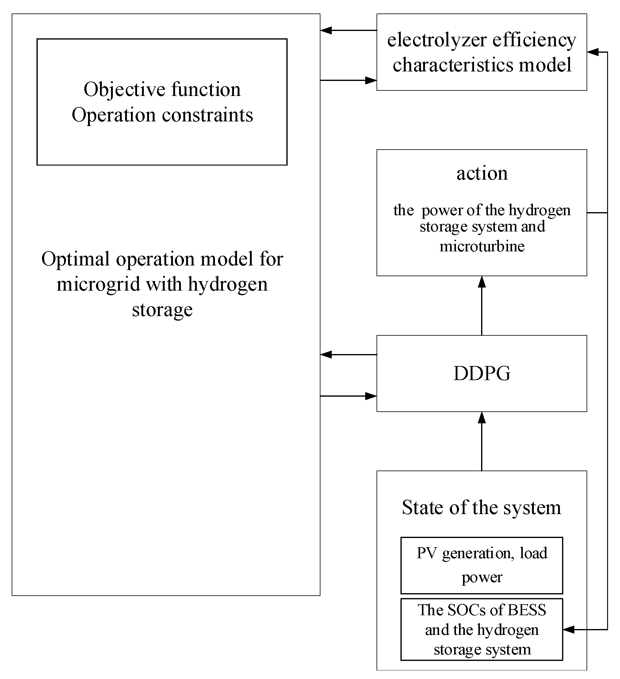
4. Optimal Operation of Microgrid Based on DDPG

4.1. State Space

The state space needs to include the factors that impact the strategy. For the optimal operation of the PV-hydrogen energy system, the parameters of the state space include the power generation of PV, the load, the SOC of BESS, and the SOC of hydrogen storage. Therefore, the state space contains four states and can be expressed as
s t = { P t P V , P t l o a d , S t b , S t h 2 }
where S t is the state space, which is the input of the policy network. Thus, the dimension of the input layer of the DDPG policy network is 4.

4.2. Action Space

The decision variables of the microgrid operation optimization include the output of microturbine, the charging and discharging power of BESS, the charging and discharging power of hydrogen storage system, curtailment of PV generation, and curtailment of load power at time t. In order to avoid a high dimension action space of deep reinforcement learning, where the agent has difficulty of exploring the feasible solution, the action space of the microgrid operation optimization problem is expressed by microturbine output and hydrogen storage system charging/discharging power as:
a t = { P t h 2 , P t M T }
After the agent selects the action, the values of other decision variables were determined by the following rules. Firstly, the unbalanced power of electric energy after the agent selects the action was calculated according to Equation (37):
P t e x t r a = P t P V P t l o a d P t h 2 + P t M T
where P t e x t r a is the unbalanced power of the system.
When the unbalanced power is positive, it indicates that the power generation of the system is large. At this scenario, the BESS is set to charge power. When the unbalanced power is negative, which represents that the power generation of the system is insufficient, and BESS is set to discharge power. Since output power of BESS is affected by the constraints of SOC, the maximum charging and discharging power under the current SOC can be calculated by the following formula:
P t c h a , max = ( 1 S t b ) E b η b Δ t
P t d i s , max = S b t E b ζ b Δ t
where P t c h a , max is the maximum allowable charging power under the SOC at time t; P t d i s , max is the maximum allowable discharge power under the SOC at time t.
The charging and discharging power of BESS were calculated by comprehensively considering the power limits and SOC constraints, as shown in Equation (39). Finally, the curtailment of PV generation and the curtailment of load power of the system were calculated according to the charging/discharging power of BESS and the imbalance power of the system, as shown in Equations (41) and (42).
The flowchart is shown in Figure 5:
P t b = { min ( P t c h a , max , P max b , P t e x t r a ) P t e x t r a 0 max ( P t d i s , max , P min b , P t e x t r a ) P t e x t r a < 0
P t l o s s = P t e x t r a P t b P t e x t r a < 0
P t c u r t = P t e x t r a P t b P t e x t r a 0
At each scheduling time t, the action vector a t with dimension 2 is generated by the strategy network under the state s t . Therefore, the output layer dimension of the policy network is 2. Since s t and a t are both inputs of the evaluation network, the input layer dimension of the evaluation network is 6.

4.3. Reward Function

The goal of the intelligence in the learning process is to maximize the reward. The optimal policy must satisfy the constraints of the microgrid model. Thus, the constraints need to be reasonably transformed into the reward function. The equipment power is constrained by the upper and lower limits of the action space. The SOC constraints of BESS are met in the decision-making process. Therefore, it is only necessary to add the SOC constraints of the hydrogen storage system to the reward function in the form of a penalty function as:
D 1 = { 1 S t h 2 > S max h 2 0 S min h 2 S t h 2 S max h 2 1 S t h 2 < S min h 2
where D 1 is the hydrogen storage system SOC penalty function.
The microgrid operates in an off-grid mode. In order to reduce the amount of load shedding and PV curtailment to improve the utilization of renewable energy, the costs of load shedding and PV curtailment are added into the reward function as part of the microgrid operation cost:
D 2 = ρ ( P t c u r t + P t l o s s ) Δ t
where D 2 represents the total cost of load shedding and PV curtailment; ρ is the cost coefficient.
Since the objective of the proposed model is to minimize the microgrid operating cost, the reward function for each dispatch period contains the power system operating cost F t , the hydrogen storage SOC penalty function D 1 , and the cost of load shedding and PV curtailment D 2 .
Moreover, deep reinforcement learning is a process of maximizing the cumulative reward, so the operating cost in the reward function needs to be expressed as a negative value as:
r t = F t D 2 + D 1

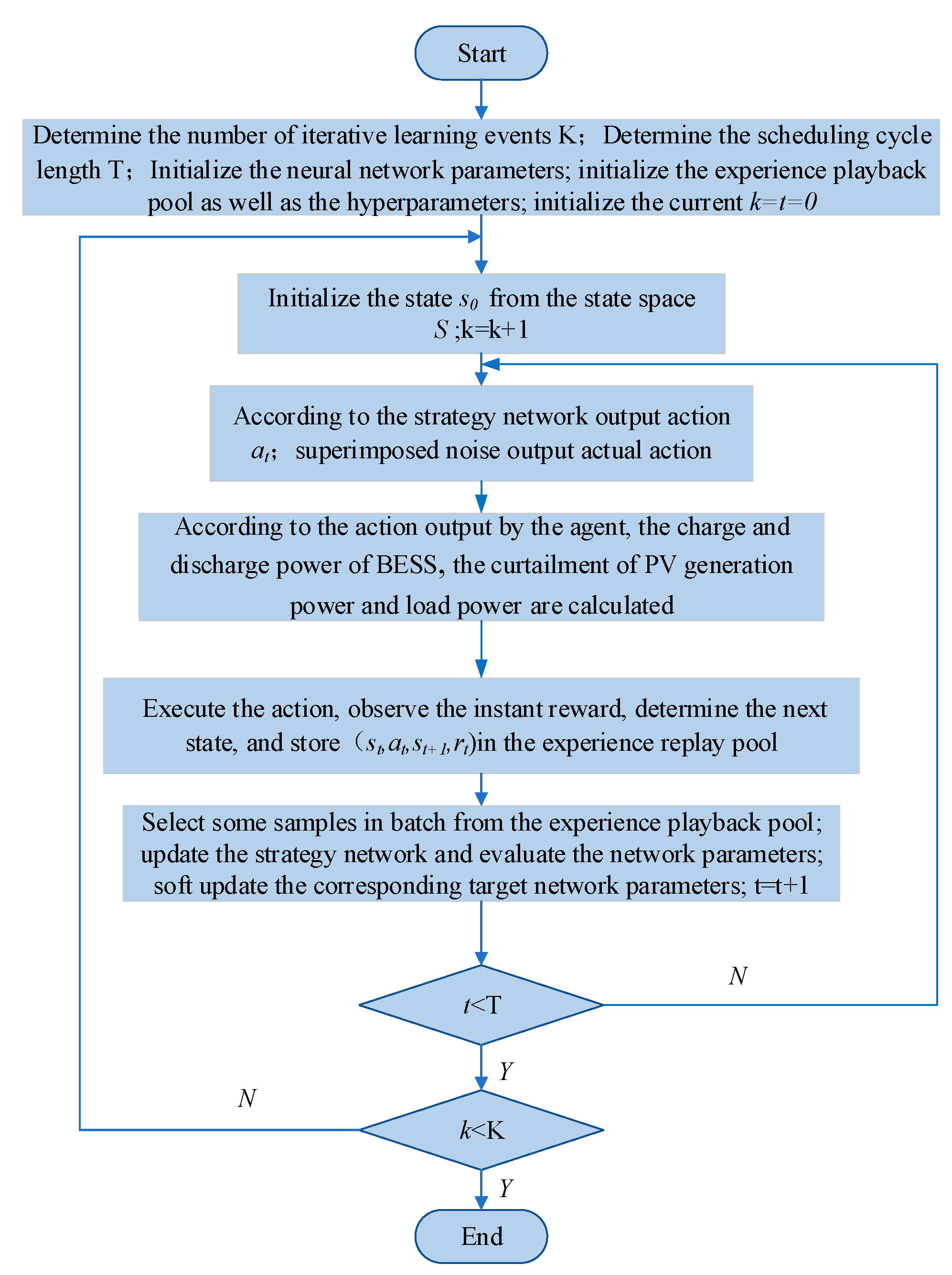
4.4. Process of the Optimal Operation Method

The flowchart of the proposed optimal operation method of the microgrid based on DDPG is shown in Figure 6.

5. Case Studies

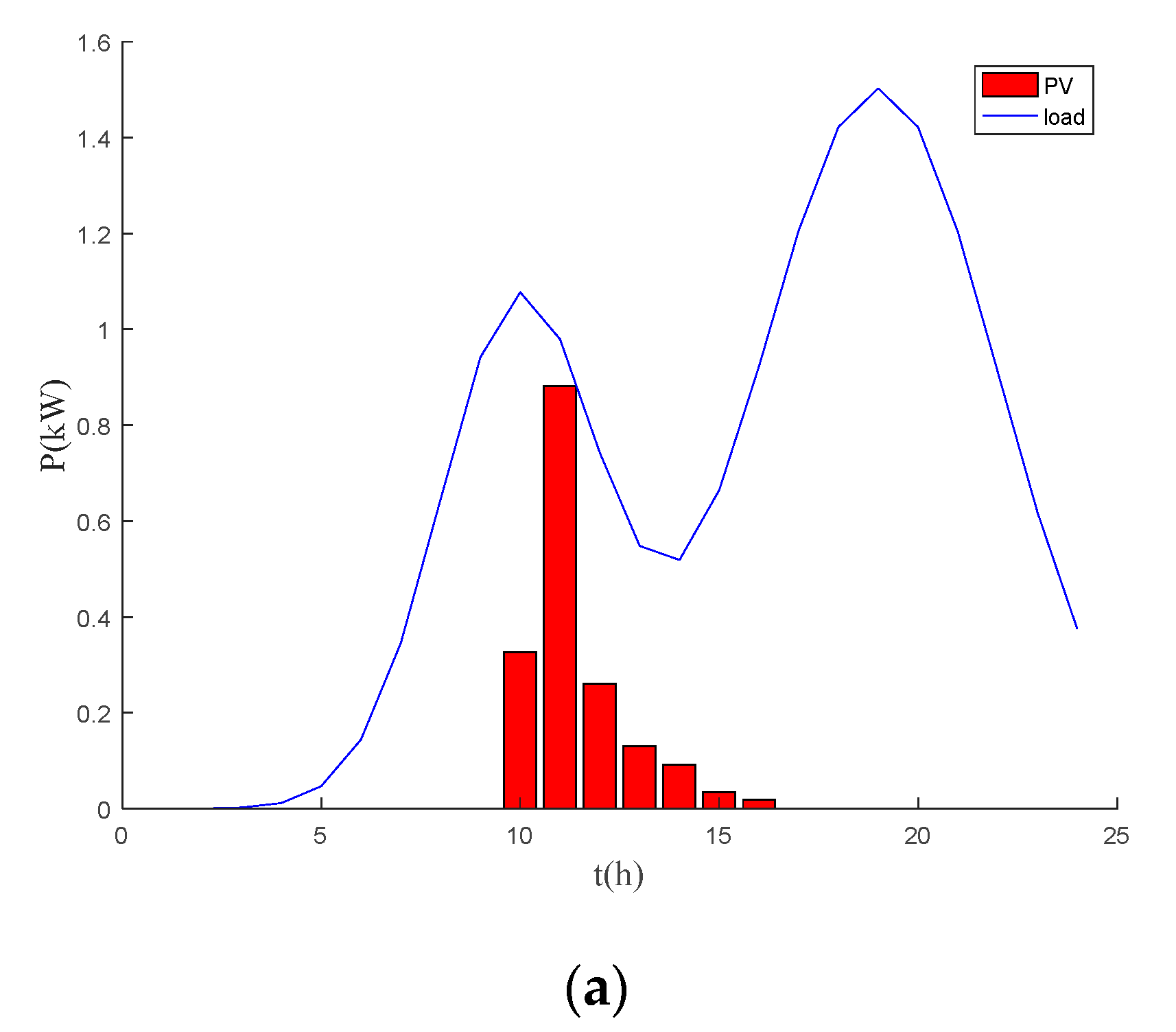
5.1. Simulation Environment

The microgrid used for study is shown in Figure 1. The parameters of electrolyzer efficiency characteristics are shown in Table 1, and the power limits and cost parameters of the equipment in the microgrid are shown in Table 2 [25]. The capacity of the hydrogen storage tank is 200 kWh. The electrochemical storage capacity is 2.9 kWh. The efficiency of the fuel cell is 0.65, and the charging and discharging efficiencies of the electrochemical storage are both 0.95. The microturbine cost parameters δ 2 , δ 1 , δ 0 are 0.001166 USD/kW2, 0.03677 USD/kW, and 0.06829 USD/kW, respectively; The cost efficiency of load shedding and PV curtailment is 0.3152 USD/kWh. The factor of CO2 emission is 724 kg/kW, and the carbon emission price in the carbon trading market of Beijing in China is 0.009079 USD/kg. The data of PV and load are from [26]. The curves of PV generation and load forecast for a typical day are shown in Figure 7.

5.2. Simulation Results

5.2.1. Simulation Results of Electrolyzer Efficiency Characteristics

In order to study the effect of the electrolyzer efficiency characteristic on the microgrid operation scheduling, the capacity of the hydrogen storage tank is set as 10 kWh. In the case where the efficiency characteristic is not considered, the efficiency of the electrolyzer is set as a constant that is 0.65 from the literature [21].
The scheduling scheme of the constant efficiency case is applied to the more accurate electrolyzer model considering efficiency characteristic. Additionally, the SOCs of BESS and hydrogen storage are shown in Figure 8b. In contrast, the simulation results using the efficiency characteristic model are shown in Figure 8a. The microgrid operation costs under different electrolyzer models are shown in Table 3.
As shown in Table 3, the operating cost under the model considering electrolyzer efficiency characteristic is minimum. The constant efficiency models result in larger operating costs. It can be seen from Figure 8 that the maximum SOC of hydrogen storage under constant efficiency model is much less than 1. Under the model consider efficiency characteristic, the SOC of hydrogen storage reaches 1 at certain time steps. This means that adopting the model with efficiency characteristics can better utilize the hydrogen storage capacity and further reduce the operating cost.

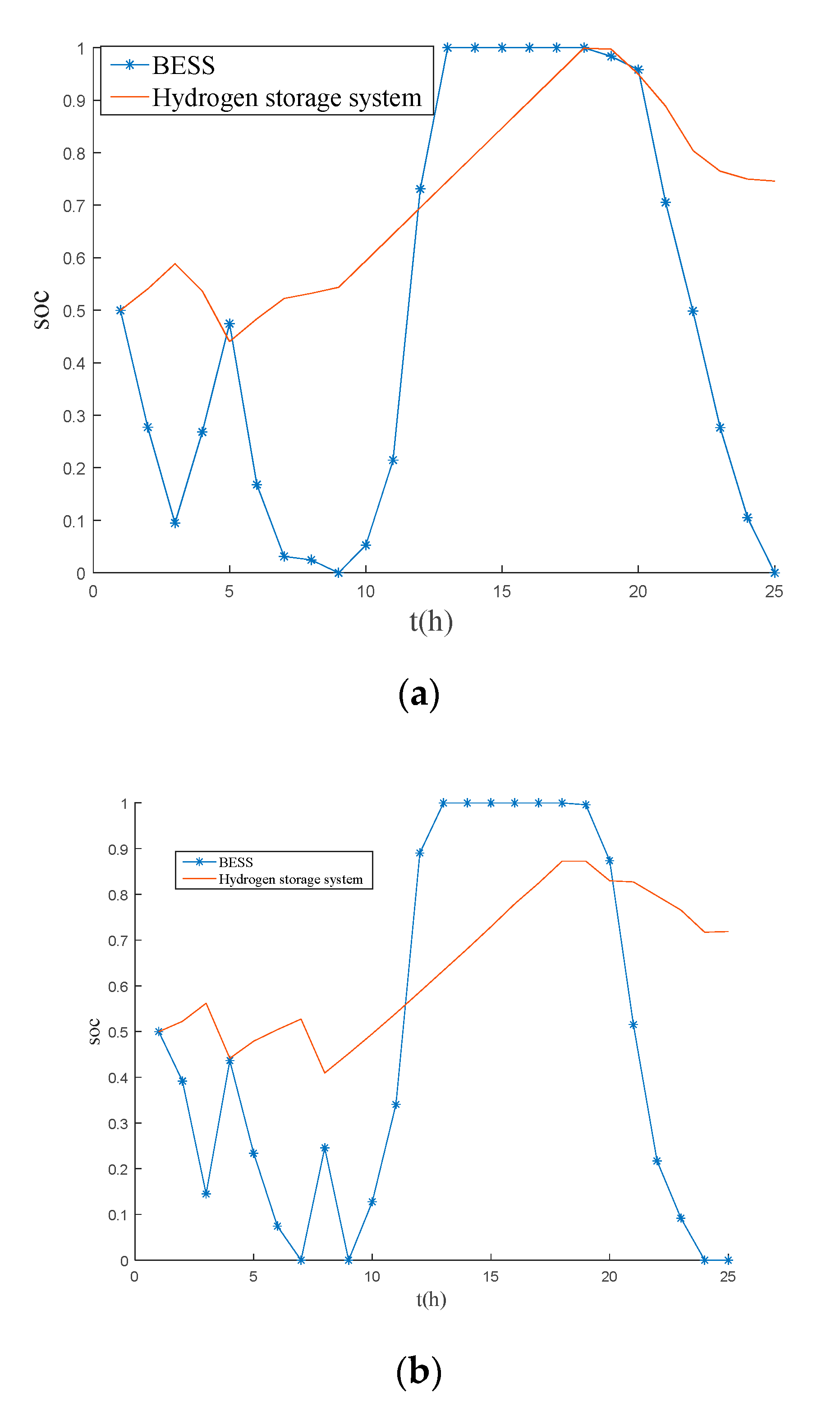
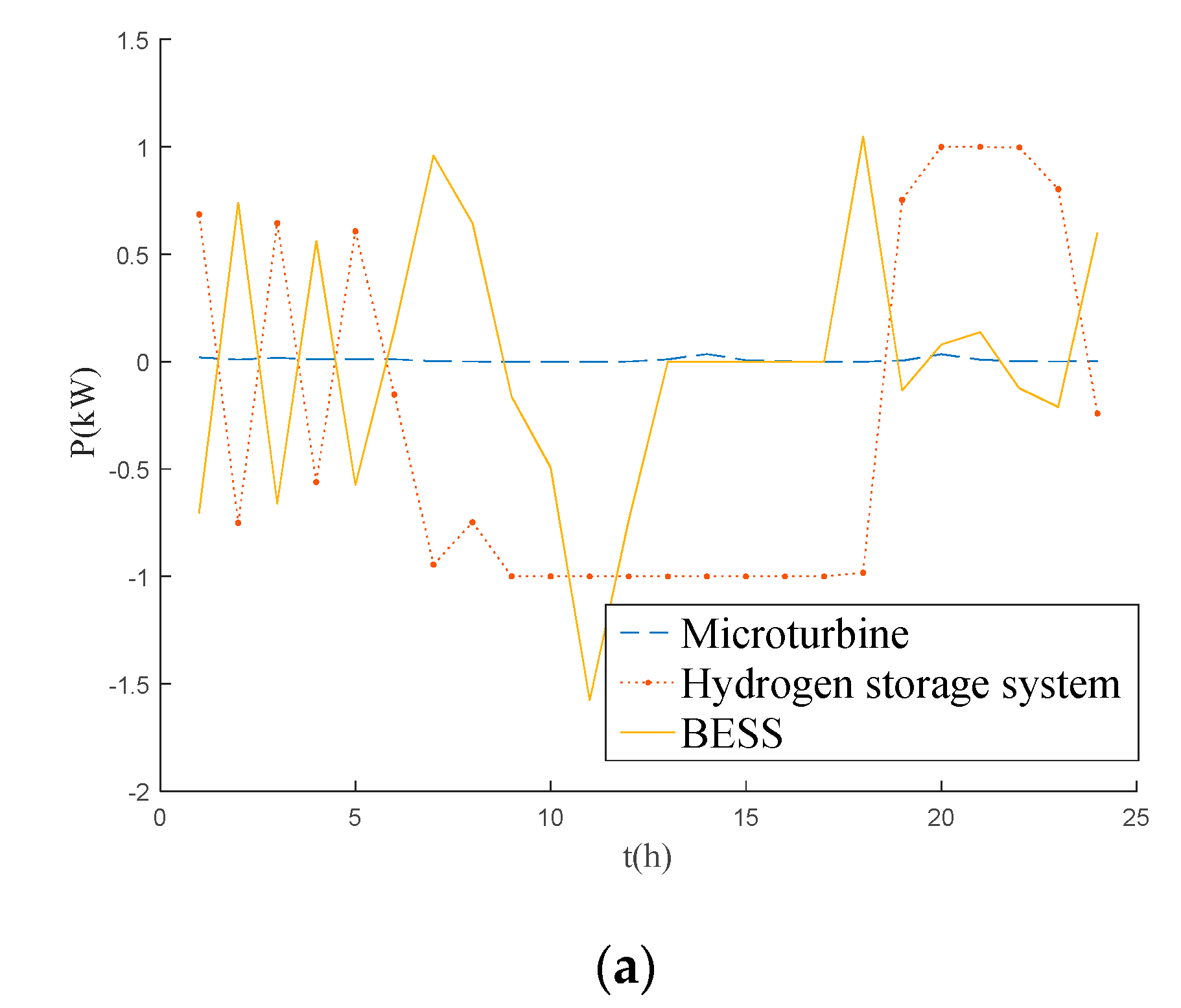
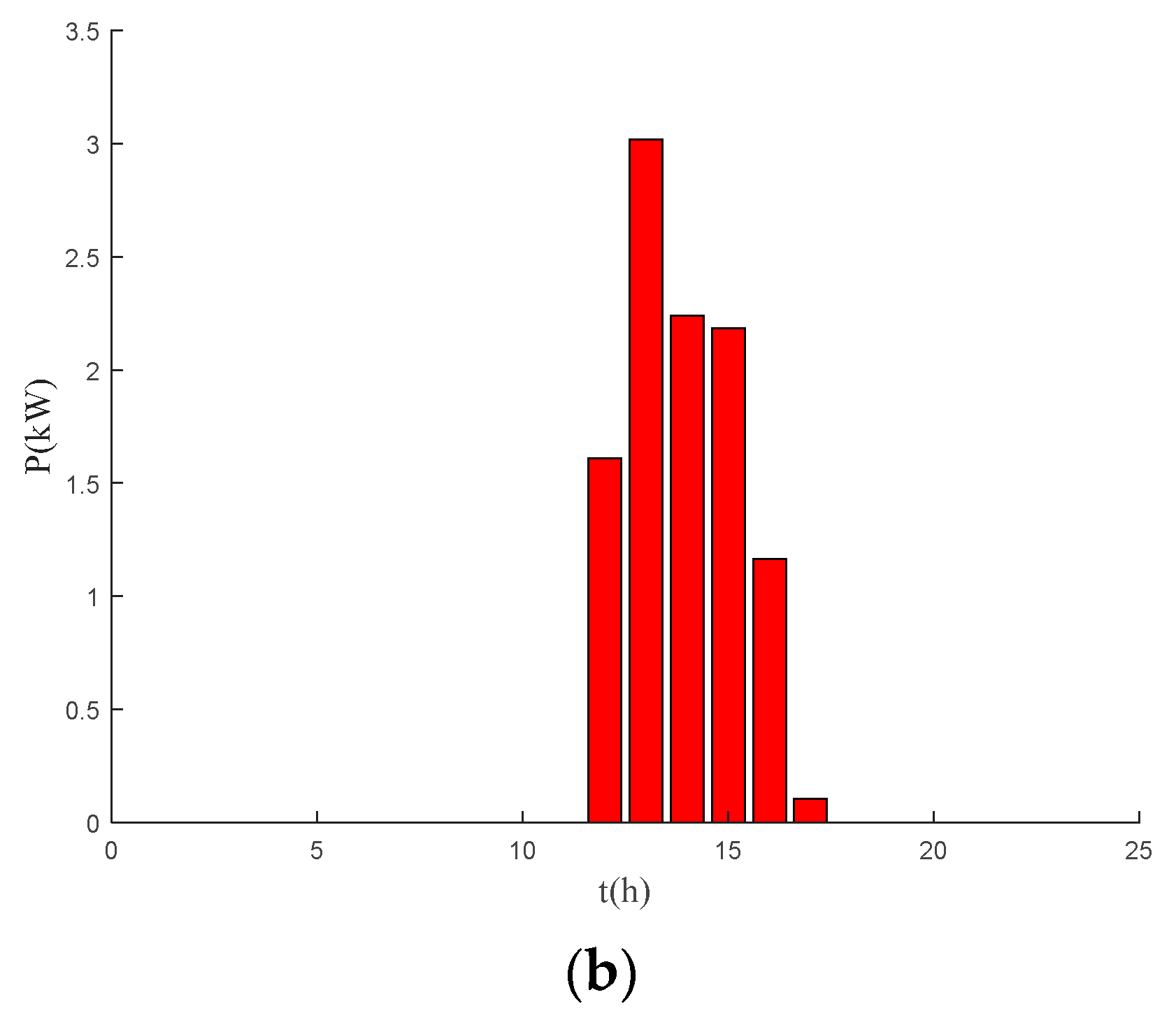
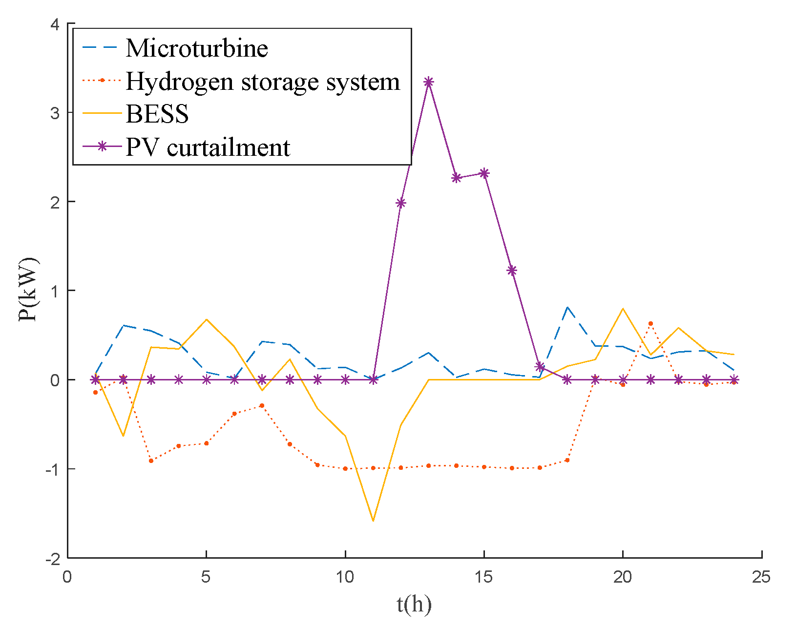
5.2.2. Simulation Results of DDPG Algorithm

Deep reinforcement learning needs to train a neural network in a short time and use it for action decision making and value estimation. Thus, deep reinforcement learning usually has a relatively shallow network to ensure fast training. Moreover, a too deep and wide neural network structure can easily lead to over-fitting. Finally, the network structure with two hidden layers is adopted through experiments. The strategy network in the DDPG algorithm in this study consists of a 4-dimensional input layer, 2 hidden layers with 64 neurons, and an output layer for actions. The evaluation network consists of a 4-dimensional input layer for states, a 2-dimensional input layer for actions, 2 hidden layers with 64 neurons, and an output layer for outputting Q values. The structure of neural network is shown in Figure 9.
The decay rate of the DDPG algorithm γ is 0.9. The learning rate of the strategy network is 0.0001. The learning rate of the evaluation network is 0.001. A total of 64 samples are selected for each learning process. The size of the experience pool is 10,000. The standard deviation of Gaussian noise is 1. The standard deviation of Gaussian noise is reduced to 0.9995 times of the original for each scheduling period during the learning process. Additionally, the number of iterations is set as 2000.
The reward value curve during the training of the algorithm is shown in Figure 10. It can be seen that, after 1000 rounds, the reward value is basically stable, and the algorithm converges. The operating cost of the microgrid is USD 5.29.
From Figure 11a, we can see that, in the time period from 8:00 to 17:00, the PV generation increases and the BESS starts to charge. The electrolyzer also produces hydrogen, and the BESS stops acting after it is fully charged. In the time period from 18:00 to 23:00 when the PV generation decreases and the load demand is high, the hydrogen storage is mainly used for power generation at these time steps because the hydrogen storage has a larger capacity.
Figure 11b shows the curtailment of PV generation and load. A positive value means the microgrid has excess generation, resulting in curtailment of PV generation. A negative value means the load is more than the generation and a part of load is shed. As can be seen, there is no load shedding in the microgrid, and all load demands are met. However, there is curtailment of PV generation during the time steps from 11:00 to 17:00.

5.2.3. Performance Evaluation

In order to test the performance of the proposed optimal operation method for the microgrid, the proposed algorithm is compared with the genetic algorithm (GA) [27] and the interior point method [28]. The DDPG algorithm is implemented in Python using the TensorFlow framework. The interior point method and GA are conducted in MATLAB. The interior point method is implemented using the ‘fmincon’ function in the optimization toolbox. The genetic algorithm is implemented using the ‘ga’ function. The simulation results are shown in Figure 12 and Figure 13. Table 4 summarizes the operating costs of the microgrid using the three methods.
  • Method1: Optimize the operation of microgrids using DDPG algorithm;
  • Method2: Optimize the operation of the microgrid using the GA;
  • Method3: Optimize the operation of the microgrid using the interior point method.
It can be seen that the operating costs of method 2 and method 3 are higher than that of method 1. In method 2 and method 3, the expensive microturbine is used for too many times. In contrast, in method 1, the cheap fuel cell is used more often. In total, the operating cost of method 1 is the least. The operating cost not only covers the economic benefits of the microgrid system operation, but also takes into account the environmental benefits of the microgrid. Through the simulation experiment, the proposed DDPG method has the minimum operating cost compared to the traditional methods.

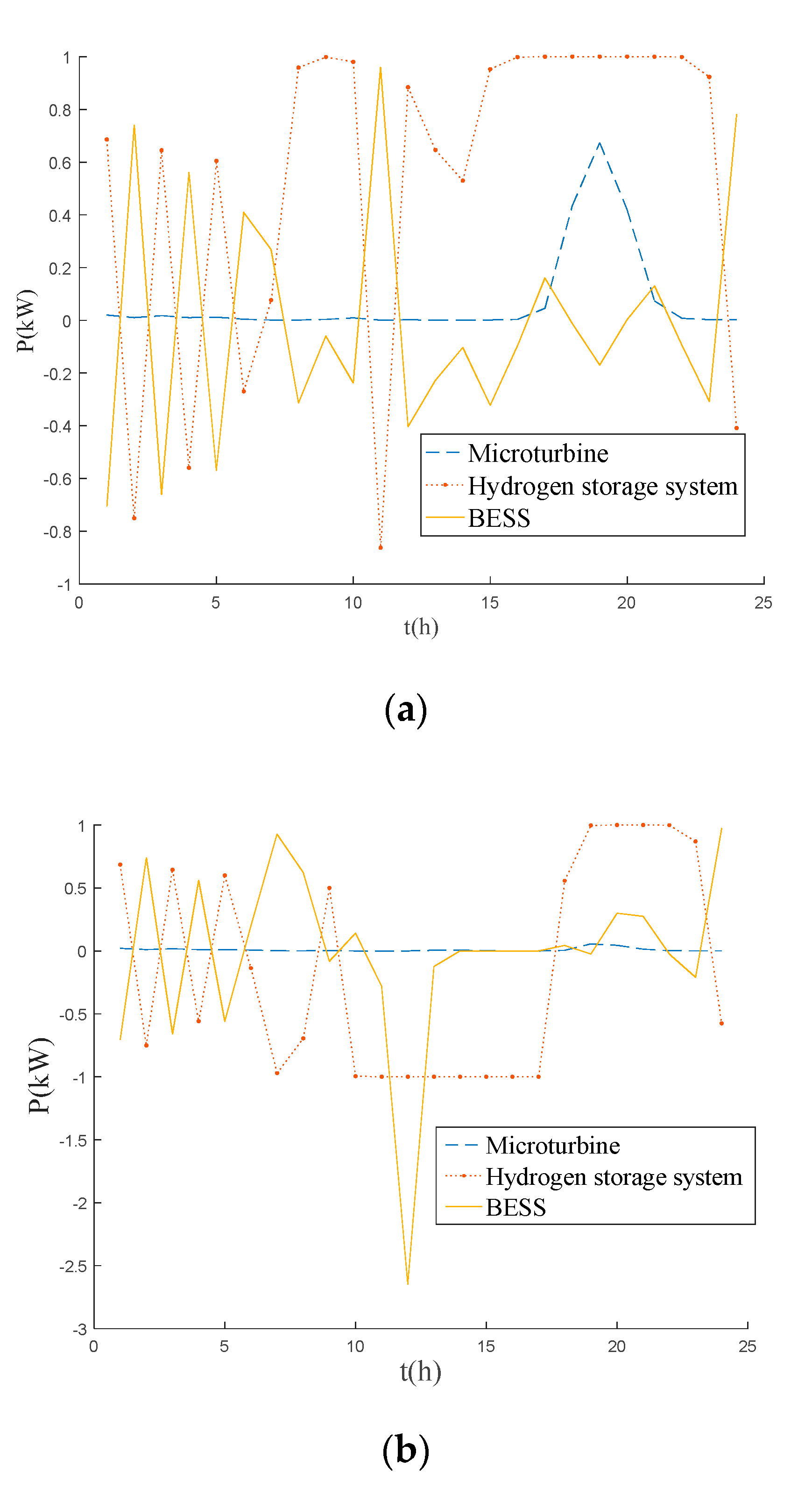
5.2.4. Generalization Analysis

To investigate the generalization of the DDPG algorithm in new scenarios, the already trained DDPG model is tested in new winter and summer scenarios, since the load and PV generation curves differ in shapes. The load and PV generation curves are shown in Figure 14. The trained model was used for the new scenarios and the results are shown in Figure 15.
From the simulation results, it can be seen that in winter the PV generation is not enough to support the load demand. The hydrogen storage system is discharged most of the time, and the microturbine is put into use at peak hours from 16:00 to 22:00. Since the PV generation power in winter is low, there is no PV curtailment in winter.
In summer, the PV generation is high. The load demand can be met under the regulation of BESS and the hydrogen storage system. From 9:00 to 17:00, the PV generation is larger, and the hydrogen storage system is in the charging state. From 17:00 to 23:00, the load peak is at peak hours, and the hydrogen storage system is in the discharging state.
To compare with the DDPG algorithm, the GA method is applied to the new scenarios, and the results are shown in Table 5.
As shown in Table 5, the trained DDPG model can be applied to new scenarios directly without additional training, and the operating cost of the microgrid is less than that using the GA, which indicates that the proposed algorithm has a certain generalization after training, and can reduce the operating cost of the hydrogen microgrid.

6. Conclusions

This paper proposes a refined model to represent the electrolyzer efficiency characteristics using the linear interpolation method. The electrolyzer efficiency characteristic model is combined with the model of the microgrid with hydrogen storage. Additionally, an optimal operation method based on the DDPG algorithm is proposed for the microgrid. According to the simulation results, the following conclusions can be drawn:
  • The electrolyzer efficiency characteristics model using linear interpolation method can describe the operation of electrolyzer more accurately. The proposed optimal operation method for the microgrid considering electrolyzer efficiency characteristics can reduce the PV curtailment and reduce the microgrid operation cost;
  • The optimal microgrid operation method based on DDPG algorithm can effectively reduce the operation cost and improve the microgrid efficiency compared with the method based on traditional algorithms, such as the GA and interior point method;
  • The optimal microgrid operation method based on DDPG algorithm has a certain generalization and can be used in in different scenarios.
However, the uncertainties of PV and load are not considered in this research, and the fuel cell efficiency is ignored. Future work will focus on the microgrid operation optimization strategy under uncertain environments and take into account the characteristics of fuel cell to make the operation model more realistic.

Author Contributions

Conceptualization, Z.Z. and Z.W.; methodology, Z.Z.; software, Z.W.; validation, Z.Z., Z.W. and H.Z.; formal analysis, Z.Z.; investigation, H.Z.; resources, Z.Z.; data curation, H.Z. and Z.W.; writing—original draft preparation, Z.W.; writing—review and editing, Z.Z.; visualization, Z.W.; supervision, Z.Z.; project administration, Z.Z.; funding acquisition, Z.Z. All authors have read and agreed to the published version of the manuscript.

Funding

This research was funded by the Young and Middle-aged Teachers Education Scientific Research Projects of Fujian Province Education Department (No. JAT190043) and Scientific Research Foundation of Fuzhou University (No. 510901).

Conflicts of Interest

The authors declare no conflict of interest.

Abbreviations

AbbreviationDescription
GAMSGeneral algebraic modeling system
DDPGDeep deterministic policy gradient
PVPhotovoltaic
BESSBattery energy storage system
SOFCSolid oxide fuel cell
SOCState of charge
GAGenetic algorithm

References

  1. Mah, A.X.Y.; Ho, W.S.; Hassim, M.H.; Hashim, H.; Ling, G.H.T.; Ho, C.S.; Ab Muis, Z. Optimization of a standalone photovoltaic-based microgrid with electrical and hydrogen loads. Energy 2021, 235, 121218. [Google Scholar] [CrossRef]
  2. Hatziargyriou, N.; Asano, H.; Iravani, R.; Marnay, C. Microgrids. IEEE Power Energy Mag. 2007, 5, 78–94. [Google Scholar] [CrossRef]
  3. Shatnawi, M.; Al Qaydi, N.; Aljaberi, N.; Aljaberi, M. Hydrogen-Based Energy Storage Systems: A Review. In Proceedings of the 2018 7th International Conference on Renewable Energy Research and Applications (ICRERA), Paris, France, 14–17 October 2018. [Google Scholar]
  4. Ji, Y.; Wang, J.; Xu, J.; Fang, X.; Zhang, H. Real-Time Energy Management of a Microgrid Using Deep Reinforcement Learning. Energies 2019, 12, 2291. [Google Scholar] [CrossRef] [Green Version]
  5. Daneshvar, M.; Mohammadi-Ivatloo, B.; Zare, K.; Asadi, S. Transactive energy management for optimal scheduling of interconnected microgrids with hydrogen energy storage. Int. J. Hydrog. Energy 2020, 46, 16267–16278. [Google Scholar] [CrossRef]
  6. Akbari-Dibavar, A.; Daneshvar, M.; Mohammadi-Ivatloo, B.; Zare, K.; Anvari-Moghaddam, A. Optimal Robust Energy Management of Microgrid with Fuel Cells, Hydrogen Energy Storage Units and Responsive Loads. In Proceedings of the 2020 International Conference on Smart Energy Systems and Technologies (SEST), Istanbul, Turkey, 7–9 September 2020. [Google Scholar]
  7. Nojavan, S.; Akbari-Dibavar, A.; Farahmand-Zahed, A.; Zare, K. Risk-constrained scheduling of a CHP-based microgrid including hydrogen energy storage using robust optimization approach. Int. J. Hydrog. Energy 2020, 45, 32269–32284. [Google Scholar] [CrossRef]
  8. Nojavan, S.; Zare, K.; Mohammadi-Ivatloo, B. Application of fuel cell and electrolyzer as hydrogen energy storage system in energy management of electricity energy retailer in the presence of the renewable energy sources and plug-in electric vehicles. Energy Convers. Manag. 2017, 136, 404–417. [Google Scholar] [CrossRef]
  9. Konstantinopoulos, S.A.; Anastasiadis, A.G.; Vokas, G.A.; Kondylis, G.P.; Polyzakis, A. Optimal management of hydrogen storage in stochastic smart microgrid operation. Int. J. Hydrog. Energy 2017, 43, 490–499. [Google Scholar] [CrossRef]
  10. Gong, X.; Dong, F.; Mohamed, M.A.; Abdalla, O.M.; Ali, Z.M. A Secured Energy Management Architecture for Smart Hybrid Microgrids Considering PEM-Fuel Cell and Electric Vehicles. IEEE Access 2020, 8, 47807–47823. [Google Scholar] [CrossRef]
  11. Dufo-López, R.; Bernal-Agustín, J.L.; Contreras, J. Optimization of control strategies for stand-alone renewable energy systems with hydrogen storage. Renew. Energy 2007, 32, 1102–1126. [Google Scholar] [CrossRef]
  12. García-Triviño, P.; Fernández-Ramírez, L.M.; Gil-Mena, A.J.; Llorens-Iborra, F.; García-Vázquez, C.A.; Jurado, F. Optimized operation combining costs, efficiency and lifetime of a hybrid renewable energy system with energy storage by battery and hydrogen in grid-connected applications. Int. J. Hydrog. Energy 2016, 41, 23132–23144. [Google Scholar] [CrossRef]
  13. Wang, S.; Duan, J.; Shi, D.; Xu, C.; Li, H.; Diao, R.; Wang, Z. A Data-driven Multi-agent Autonomous Voltage Control Framework Using Deep Reinforcement Learning. IEEE Trans. Power Syst. 2020, 35, 4644–4654. [Google Scholar] [CrossRef]
  14. Diao, R.; Wang, Z.; Shi, D.; Chang, Q.; Duan, J.; Zhang, X. Autonomous Voltage Control for Grid Operation Using Deep Reinforcement Learning. In Proceedings of the IEEE Power & Energy Society General Meeting (PESGM), Atlanta, GA, USA, 4–8 August 2019; pp. 1–5. [Google Scholar]
  15. Wan, Z.; Li, H.; He, H.; Prokhorov, D. Model-Free Real-Time EV Charging Scheduling Based on Deep Reinforcement Learning. IEEE Trans. Smart Grid 2018, 10, 5246–5257. [Google Scholar] [CrossRef]
  16. López, K.L.; Gagné, C.; Gardner, M.A. Demand-Side Management Using Deep Learning for Smart Charging of Electric Vehicles. IEEE Trans. Smart Grid 2018, 10, 2683–2691. [Google Scholar] [CrossRef]
  17. Ye, Y.; Qiu, D.; Sun, M.; Papadaskalopoulos, D.; Strbac, G. Deep Reinforcement Learning for Strategic Bidding in Electricity Markets. IEEE Trans. Smart Grid 2020, 11, 1343–1355. [Google Scholar] [CrossRef]
  18. Xu, H.; Sun, H.; Nikovski, D.; Kitamura, S.; Mori, K.; Hashimoto, H. Deep Reinforcement Learning for Joint Bidding and Pricing of Load Serving Entity. IEEE Trans. Smart Grid 2019, 10, 6366–6375. [Google Scholar] [CrossRef]
  19. Ye, Y.; Qiu, D.; Wu, X.; Strbac, G.; Ward, J. Model-Free Real-Time Autonomous Control for a Residential Multi-Energy System Using Deep Reinforcement Learning. IEEE Trans. Smart Grid 2020, 11, 3068–3082. [Google Scholar] [CrossRef]
  20. Bian, H.; Tian, X.; Zhang, J.; Han, X. Deep Reinforcement Learning Algorithm Based on Optimal Energy Dispatching for Microgrid. In Proceedings of the 2020 5th Asia Conference on Power and Electrical Engineering (ACPEE), Chengdu, China, 4–7 June 2020. [Google Scholar]
  21. Domínguez-Barbero, D.; García-González, J.; Sanz-Bobi, M.A.; Sánchez-Úbeda, E.F. Optimising a Microgrid System by Deep Reinforcement Learning Techniques. Energies 2020, 13, 2830. [Google Scholar] [CrossRef]
  22. Pan, G.; Gu, W.; Lu, Y.; Qiu, H.; Lu, S.; Yao, S. Optimal Planning for Electricity-Hydrogen Integrated Energy System Considering Power to Hydrogen and Heat and Seasonal Storage. IEEE Trans. Sustain. Energy 2020, 11, 2662–2676. [Google Scholar] [CrossRef]
  23. Deng, Z.; Jiang, Y. Optimal sizing of a wind-hydrogen system under consideration of the efficiency characteristics of electrolysers. Renew. Energy Resour. 2020, 38, 259–266. [Google Scholar]
  24. Du, Y.; Li, F. Intelligent Multi-Microgrid Energy Management Based on Deep Neural Network and Model-Free Reinforcement Learning. IEEE Trans. Smart Grid 2020, 11, 1066–1076. [Google Scholar] [CrossRef]
  25. Yu, P.; Song, T.; Yuan, T.; Han, X. Economic Operation of Regional Integrated Energy System Considering Cogeneration of Fuel Cell. Proc. CSU-EPSA 2021, 33, 9. [Google Scholar]
  26. François-Lavet, V.; Taralla, D. DeeR. 2016. Available online: http://deer.readthedocs.io (accessed on 16 April 2020).
  27. Raghavan, A.; Maan, P.; Shenoy, A.K. Optimization of Day-Ahead Energy Storage System Scheduling in Microgrid Using Genetic Algorithm and Particle Swarm Optimization. IEEE Access 2020, 8, 173068–173078. [Google Scholar] [CrossRef]
  28. Valencia, F.; Sáez, D.; Collado, J.; Ávila, F.; Marquez, A.; Espinosa, J.J. Robust Energy Management System Based on Interval Fuzzy Models. IEEE Trans. Control. Syst. Technol. 2016, 24, 140–157. [Google Scholar]
Figure 1. Schematic diagram of the microgrid.
Electronics 11 00196 g001
Figure 2. Electrolyzer efficiency characteristic.
Electronics 11 00196 g002
Figure 3. Block diagram of the optimal operation of the microgrid.
Electronics 11 00196 g003
Figure 4. Fundamentals of reinforcement learning.
Electronics 11 00196 g004
Figure 5. Flowchart of decision making.
Electronics 11 00196 g005
Figure 6. The flowchart of optimal operation of microgrid.
Electronics 11 00196 g006
Figure 7. Typical daily PV and load forecast curves.
Electronics 11 00196 g007
Figure 8. Simulation results under different electrolyzer efficiency models. (a) Simulation results of the model considering the efficiency characteristic of the electrolyzer. (b) The simulation results of the model using a constant electrolyzer efficiency.
Electronics 11 00196 g008
Figure 9. Architecture of the network. (a) The strategy network. (b) The evaluation network.
Electronics 11 00196 g009
Figure 10. Convergence curve of the DDPG algorithm.
Electronics 11 00196 g010
Figure 11. Scheduling results of microgrid based on the DDPG algorithm. (a) Scheduling results of microgrid. (b) Curtailment of PV generation and load.
Electronics 11 00196 g011aElectronics 11 00196 g011b
Figure 12. Scheduling results of microgrid using method 2.
Electronics 11 00196 g012
Figure 13. Scheduling results of microgrid using method 3.
Electronics 11 00196 g013
Figure 14. PV and load forecasting curves of new microgrid scenarios. (a) PV and load forecasting curves in winter. (b) PV and load forecasting curves in summer.
Electronics 11 00196 g014aElectronics 11 00196 g014b
Figure 15. Scheduling results of new microgrid scenarios. (a) Scheduling results of winter. (b) Scheduling results of summer. (c) PV curtailment of microgrid in summer.
Electronics 11 00196 g015aElectronics 11 00196 g015b
Table 1. Parameters of electrolyzer.
ParametersValue
Unit current density j/A·cm−20~4
Operating temperature T/K353
Universal gas constants R/J·(mol·K)−18.31446
Faraday’s constant F/C·mol−196,485.3
Cathodic charge transfer coefficient αc0.71
Anode charge transfer coefficient αa0.29
Cathode exchange current density jco/mA·cm−224.6
Anode exchange current density jao/mA·cm−224.1
Electron transfer number of cathode and anode nc, na2
Electrolyte resistance/mΩ20
Cross-sectional area of electrolyzer/cm216
Table 2. Parameters of devices in microgrid.
DeviceMaximum Power/kWMinimum Power/kWOperation and Maintenance Cost (USD/kWh)
Electrolyzer100.01262
Microturbine10/
Fuel Cell100.01325
BESS2.92.90.01311
Table 3. Operating costs under different electrolyzer efficiency models.
Electrolyzer EfficiencyMicrogrid Operating Cost/USD
Considering efficiency characteristic5.24
Constant efficiency 0.55.20
Constant efficiency 0.65.42
Constant efficiency 0.655.56
Constant efficiency 0.75.94
Table 4. Operating cost of microgrid using different algorithms.
AlgorithmMethod 1Method 2Method 3
Operating cost of microgrid/USD5.295.755.52
Table 5. Optimization results of different algorithms.
DDPGGA
Operating cost of winter/USD2.072.08
Operating cost of summer/USD5.315.70
Publisher’s Note: MDPI stays neutral with regard to jurisdictional claims in published maps and institutional affiliations.

