Article

Position Design for Reconfigurable Intelligent-Surface-Aided Indoor Visible Light Communication Systems

National Digital Switching System Engineering and Technological Research Center, Zhengzhou 450000, China
*
Author to whom correspondence should be addressed.
Electronics 2022, 11(19), 3076; https://doi.org/10.3390/electronics11193076
Submission received: 1 September 2022 / Revised: 15 September 2022 / Accepted: 20 September 2022 / Published: 27 September 2022
(This article belongs to the Section Microwave and Wireless Communications)

Abstract

:
As an emerging technology, reconfigurable intelligent surfaces (RISs) have been investigated to apply to visible light communication (VLC) systems to enhance the transmission capability of the systems, recently. However, the optimization of RIS location in VLC has not been studied. In this study, we first investigated RIS positioning design in VLC. Specifically, we set two indoor VLC scenarios with a VLC RIS composed of a mirror array. We set the achievable rates in different scenarios as the utility functions to optimize the position of the RIS array according to the placement of the access point (AP) and user. We found that the problems are nondeterministic polynomial (NP)-hard. Aiming at the different optimization problems, the particle swarm optimization (PSO) algorithm was used to confirm the optimal position of the RIS array. Unlike the traditional algorithm, we added an adaptive mutation mechanism to the algorithm to guarantee the randomness of the particle to search for the optimal solution. Finally, our simulation results showed that the proper position design of the RIS array can improve the communication performance to a greater degree, while the computational complexity required to solve the position optimization problems through the PSO algorithm can be significantly reduced compared with that required for the exhaustive search method in the case where both of the algorithms find the optimal solution.

1. Introduction

As a promising technology, visible light communication (VLC) has recently been designed to overcome the shortcomings of radio frequency (RF) communication [1]. VLC technology uses the optical intensity emitted from light-emitted diodes (LEDs) to carry the information of the input signals, and the optical power is proportional to the input current. Photodetectors (PDs) can transform the optical intensity into an electrical signal in the receiver. Normally, the intensity-modulation and direct-detection (IM/DD) Gaussian channels are mainly used in VLC [2]. VLC has several advantages: it is a green and environmental communication technology. Mass communication resources can be provided due to the nearly 400 THz frequency band of VLC, i.e., VLC can provide a wider spectrum and higher cell density compared with RF communication [3]. We can achieve communication if the illumination need is satisfied via VLC. However, visible light cannot penetrate most obstacles, which guarantees secure communication [4].
However, there are several shortcomings that limit the development of VLC. The most significant limitation of VLC is its high dependence on line-of-sight (LoS) transmission; this high dependence easily causes loss of signal when the transmitter and receiver are not aligned. In order to solve this challenging problem, reconfigurable intelligent surface (RIS) technology in RF communication systems can be applied to VLC to enhance the performance of communication. As an emerging technology, RIS can be used to reconfigure the wireless propagation environment by adjusting the parameters of the surface comprising artificial meta-atoms. This process can be adaptively achieved with software. RIS has been studied in RF communications in recent years [5]. The availability of RIS was discussed in [6,7]. The work in [8] represents a sort of RIS design to enhance the beam-shaping capability. The difference between RIS and relaying was introduced in [9]. Hodge et al. [10] integrated RIS with MIMO technology and improved communication. In consideration of the technical bottlenecks faced by VLC and the potential of RIS, combined with the good spatial resolution provided by the nanoscale of the visible light, which is favorable for RIS accurately controlling the reflection direction, the application of RIS in VLC has been widely studied to enhance the communication quality, by promoting the achievable rate [11], energy efficiency [12], secure capacity [13,14], asymptotic capacity [15], sum rate [16], and spectral efficiency [17], and reducing the power consumption [18] and the mean square error of demodulated signals at the receiver [19]. We call this new technology VLC RIS in the rest of this paper.
The core work of the research on RISs involves investigating the proper design of RIS parameters to assist RISs in smartly controlling wireless propagation environments. These parameters mainly refer to the phase and amplitude coefficients in RF RISs and the orientation angles of mirrors in VLC RISs. As a mirror array outperforms a metasurface in VLC RISs [20], the former is widely applied, and the research on VLC RISs has mainly focused on finding the optimal combination of mirrors’ orientations. At the same time, for multiuser systems, some researchers have proposed a proper assignment scheme for the mirrors in VLC RISs to determine how VLC RIS elements serve the access points (APs) and users. The orientation angles of mirrors adaptively adjust according to the condition of the assignment scheme [14,16,17]. The assignment scheme of mirrors in VLC RISs is a new research area, and some researchers have recently investigated it. Meanwhile, another research area is the placement and position of VLC RISs. To the best of our knowledge, there is little research in this area. The work in this area with high relevance was conducted on free-space optical (FSO) communications [21,22,23]. The relevant content in RF communication was considered by [24]. Motivated by the research prospect proposed by a survey [25], we set two indoor VLC scenarios with a VLC RIS and investigated the optimal position of the RIS array when taking the achievable rate as a utility function. Our main contributions are summarized as follows:
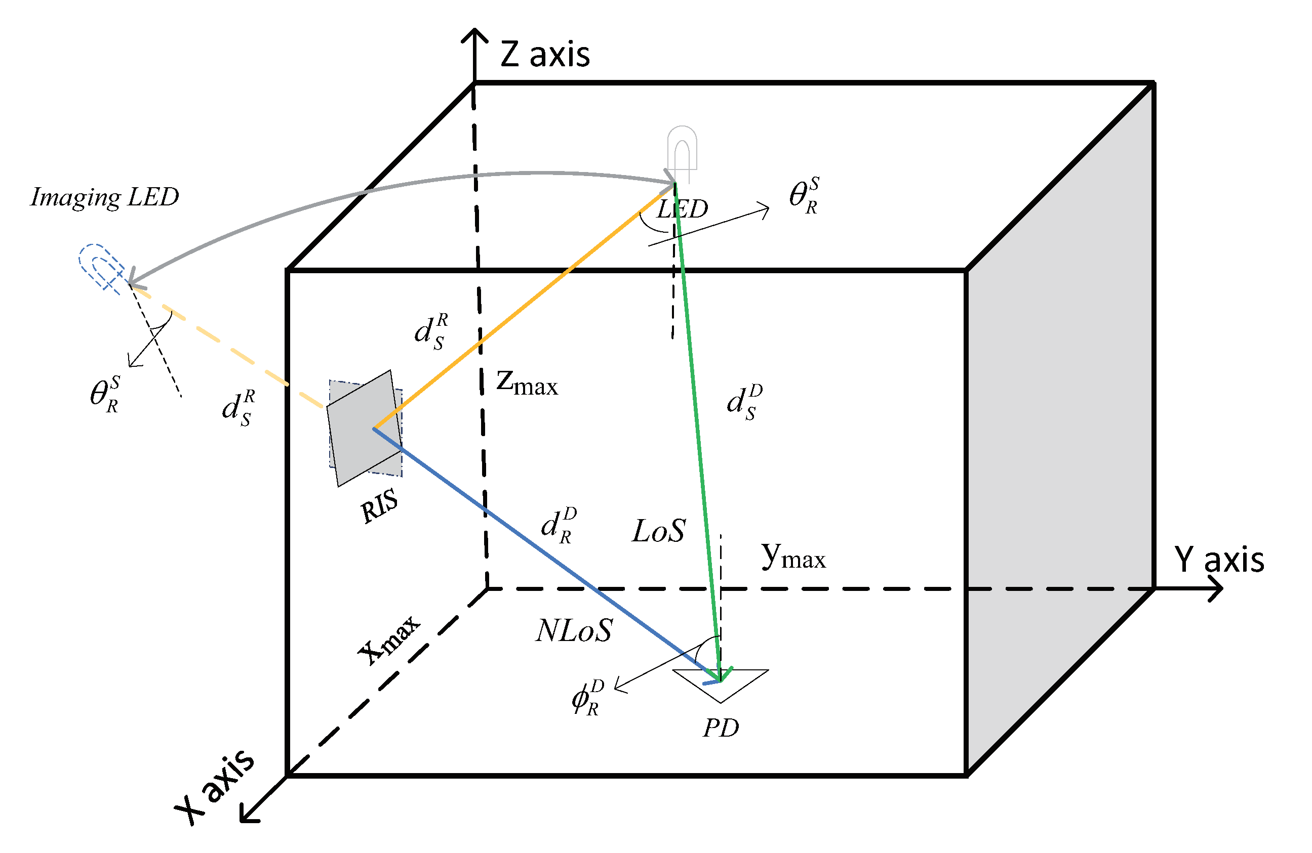
  • For the scenario that contained an AP, a user, and an RIS, we found the optimal position of the RIS after fixing the locations of the AP and user. This situation is suitable for offices with a fixed office location and LEDs. In this situation, the device generally does not move after determining the position.
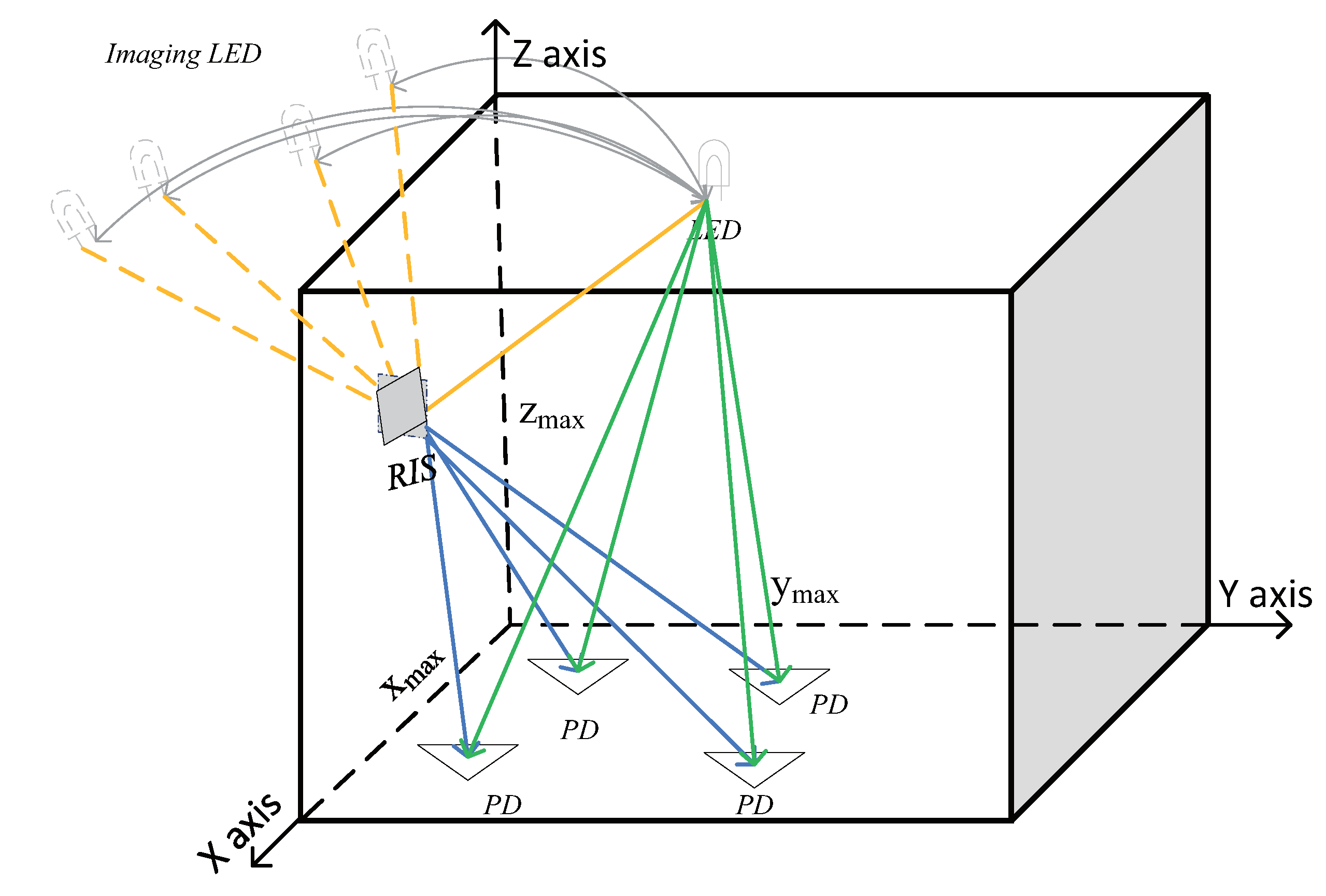
  • For the scenario with a fixed AP, a mobile user, and an RIS, we found the optimal position of the RIS to satisfy the sum of achievable rates in each position of the floor maximization. We needed to meet the limit of quality of service (QoS) for every position on the floor. Even in the traditional dead zone, we guaranteed the QoS compared with the VLC systems without RIS. This situation is suitable for offices with mobile devices and a transmitter. This is common in our daily lives.
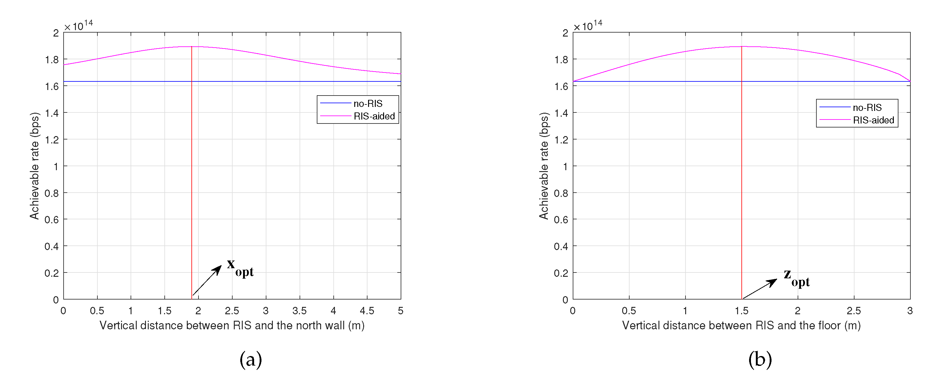
  • The simulation results showed that the communication performance can be improved to a greater degree through proper position design of the RIS (compared with the performance of a randomly placed RIS). The computational complexity to solve the position optimization problems through the PSO algorithm proposed in this paper can be significantly reduced compared with that of the exhaustive search method. We observed that the PSO algorithm is an efficient method to solve the problems described in this paper.

2. System Model

As shown in Figure 1 and Figure 2, we set two scenarios containing different VLC systems with VLC RISs. The two scenarios are common in our daily life. We considered an RIS in VLC when LoS paths exist. We aimed to add a supplement when the LoS path is blocked and wanted to know the degree of performance improvement caused by the RIS if there is a LoS transmission path. Normally, the VLC transmitter is fixed to the ceiling and the RIS array is mounted on the west wall (we denoted the four walls by the four classical directions). Consequently, we needed to determine the optimal position of the RIS array according to the placement of the user. The Cartesian coordinate system is used in the figures. We assumed the size of the room was x max × y max × z max m × m × m . For scenario 1, we considered a fixed AP, a fixed user, and an RIS with a single element. This situation is suitable for a stationary station in an office or laboratory. In this scenario, we aimed to search for the optimal position of the RIS after determining the placement sof the AP and user. For scenario 2, we considered a fixed AP, a mobile user, and an RIS with a single element. In this situation, we strove to investigate the optimal position of the RIS to satisfy the sum of achievable rates in each place of the floor maximization. We set the minimum achievable rate as the criterion to fulfill the QoS.
The channel of VLC systems contains two parts: the line-of-sight (LoS) and non-line-of-sight (NLoS) paths. The LoS channel gain h S , D LoS can usually be modeled as a Lambertian model [26]. We assumed that the NLoS links are produced only by the RIS in the remainder of the study to focus on the configuration of the RIS (i.e., the diffuse reflections caused by walls, ceiling, or floor had little influence on our RIS configuration). According to [27], high-order reflections have an insignificant impact on VLC systems. Consequently, we only considered one-order reflection in this study. For a VLC RIS based on a mirror array, the reflection process can be modeled as an imaging LED Lambertian model under the point source assumption [20]. For an RIS with a single element, the channel gain reflected via the RIS can be expressed as [28]
h S , D RIS = ρ m + 1 A P D 2 π d S , R + d R , D 2 cos m θ R S cos ϕ R D T o f G ϕ R D ,
where S denotes the AP or LED; D represents the user or photodetector (PD); ρ denotes the RIS element’s reflection coefficient; m is the Lambertian mode number determined by the LED half-power semiangle Ψ 1 / 2 , which is calculated by m = 1 / log 2 ( cos Ψ 1 / 2 ) ; A P D is the physical area of the PD. The path of transmission consists of two parts, AP-to-RIS and RIS-to-user. d S , R represents the distance between the AP and RIS, and d R , D is the distance between the RIS and the user. θ R S and ϕ R D are the angles of irradiance if the AP and incidence of the user, respectively; T o f denotes the optical filter gain; and G ϕ R D is the optical concentrator gain, which is related to the field of view (FoV) Φ FoV [26]. The optical concentrator gain can be expressed as
G ϕ R D = a 2 / sin 2 Φ FoV , 0 ϕ R D Φ FoV ; 0 , otherwise ,
where a is the refractive index at the PD. Figure 1 shows detailed examples, and the green line in Figure 1 denotes the LoS channel gain h S , D LoS . For simplicity, we do not describe the details of the LoS channel gain in the paper. The details can be obtained from [26].
This is for an RIS with only a single element, and the orientation of the RIS unit can adaptively rotate according to the position of the user, as shown in Figure 2.

3. Problem Formulation

In this section, we formulate two achievable rate maximization problems to find the optimal position of the RIS according to the two scenarios. The achievable rate of the RIS-aided VLC systems can be expressed as [29]
R x R , z R = B log 2 1 + e x p ( 1 ) 2 π p q R P D ( h S , D RIS + h S , D LoS ) N B ,
where x R , y R , z R denotes the location of the RIS with only one element, and we assume that y R is constant; B denotes the system bandwidth; p represents the transmit power; q is the conversion ratio of optical-to-electrical power; R P D is the photodetector responsiveness of the PD; and N is the power spectral density of noise. From Equation (3), we obtain that only the NLoS channel gain is charactered by the location of the RIS; consequently, the goal to maximize the achievable rate is equivalent to maximizing the NLoS channel gain h S , D RIS .

3.1. Problem Formulation for Scenario 1

For scenario 1, shown in Figure 1, the locations of the LED and PD are assumed to be known and fixed. Consequently, the decision variable in this scenario is the location of the RIS element. The decision variable is related to d S , R , d R , D , θ R S , and ϕ R D , introduced in (1). The problem can be formulated as
max cos m θ R S cos ϕ R D G ϕ R D d S , R + d R , D 2 s . t . 0 x R x max , 0 z R z max ,
This is a nonconvex optimization problem, which we solv in Section 4.

3.2. Problem Formulation for Scenario 2

For scenario 2, shown in Figure 2, we needed to look for the optimal position of the RIS to maximize the sum of the achievable rate in every position on the floor, while satisfying the quality of service (QoS) in each position on the floor. We assumed the floor is divided into N elements, so the optimization problem can be given by
max n = 1 N cos m θ R S cos ϕ R D n G ϕ R D n d S , R + d R , D n 2 s . t . 0 x R x max , 0 z R z max , R S , D n RIS > R m i n ,
where D n represents the n - th position of the floor; R m i n denotes the minimum achievable rate to satisfy the QoS.

4. Problem Solution

4.1. PSO Algorithm

In this study, we adopted the particle swarm optimization (PSO) algorithm to solve the nonconvex problems (4) and (5). The PSO algorithm is a classical metaheuristic and intelligent algorithm used to guide the particle swarm to search for the global optimization by simulating the behavior of birds, fish, and other biological populations [30]. In this paper, the position of each particle denotes the location of VLC RIS. The fitness of each particle was defined to measure the optimality of the potential solution, and the fitness was calculated by the objective function in Equations (4) and (5).
The principle of the PSO algorithm is as follows: In the beginning, each particle is randomly placed within the scope of the search space. Then, the particles adjust their search direction according to the optimal location each particle has searched and the whole particle swarm’s optimal location. After multiple searches, the particle swarm finds the optimal location, i.e., the optimal solution. The main process of this algorithm is as follows:
Each particle has two properties: the position and the velocity of the particle. The search space in the problem is a set of constraints, i.e., the feasible domain of the problems. It is assumed that there are m particles in a space of K dimensions. The ith particle is N i , and its position and velocity are X i and V i , respectively, which can be expressed as
N i = X i , V i , X i = x i 1 , x i 2 , , x i K , V i = v i 1 , v i 2 , , v i K .
We assume there are m particles gathered as a particle swarm P = N 1 , N 2 , , N m . Then, we obtain the fitness of the ith particle Y i = f X i by substituting the position of the particle as a variable into the objective function. The results are compared and used to guide the next particle’s updating. For one particle, it is assumed that the time interval of each update is T. The former velocity is V i t 1 = v i 1 t 1 , v i 2 t 1 , , v i K t 1 ; the historically optimal position of the particle is X i best = x i 1 best , x i 2 best , , x i K best ; the current position is X i t = x i 1 t , x i 2 t , , x i K t . Hence, the velocity from the current position to the historically optimal position of the particle is V i , best t = X i best X i t / T . The historically optimal position of the particle swarm is X all best = x all 1 best , x all 2 best , , x all K best , and the velocity from the current position to the historically optimal position of the particle swarm is V all , best t = X all , best X i t / T . We suppose that the velocity at this time is V i t = v i 1 t , v i 2 t , , v i K t , which can be derived by  
V i t = a 1 × V i t 1 + a 2 × V i , best t + a 3 × V all , best t ,
where a 1 , a 2 , and a 3 are the weight coefficients of these three velocities. In order to avoid missing the optimal solution due to excessive velocity or delays in reaching the optimal solution because of stagnant velocity, we needed to set a constraint on velocity. If V i t > V max , we set V i t = V max . If V i t < V min , we set V i t = V min . Then, we could update the next position
X i t + 1 = X i t + T × V i t ,
We needed to set the constraint on the position of each particle. If X i t > X max , we set X i t = X max . If X i t < X min , we set X i t = X min . Unlike the traditional algorithm, we added an adaptive mutation mechanism to the algorithm so that there is a certain probability of randomly changing the value of a particle in each iteration. Hence, we could improve the whole particle swarm’s ability to search for the optimization solution. At the same time, because of the constraints in (4) and (5), this algorithm needed to be improved. During the process of particle iteration, each particle is judged by the constraints to determine whether the position of the particle can fulfill the condition set by (4) and (5). Normal fitness calculation is performed if the particle is satisfactory; otherwise, the particle’s fitness is directly assigned to a very small number (because we were seeking the maximum value). The pseudocode of the PSO algorithm is shown in Algorithm 1.
Algorithm 1 The PSO Algorithm
Input: Swarm size m; maximum iterations G ; speed and position constraints X min , X max , V min , V max ; objective function f; weight coefficient a 1 , a 2 , a 3 ;
Output: The swarm’s historically optimum position z b e s t ; the optimal value f i t n e s s _ z b e s t ;
1:
Initialization: Position of particle swarm: p o p _ x , velocity of each particle: p o p _ v , particle’s historically optimal position: g b e s t , swarm’s historically optimal position: z b e s t .
2:
If p o p _ x is subject to the constraints in Equations (4) and (5)
3:
  Calculate the historically optimum fitness f i t n e s s _ g b e s t for each particle, select the maximum of the f i t n e s s _ g b e s t as the optimum fitness of the swarm, denoted by f i t n e s s _ z b e s t .
4:
End if
5:
While iteration < G
6:
  For the particle swarm,
7:
        update the velocity and the position of each particle according to Equations (7) and (8)
8:
    If the speed or position exceeds the predetermined boundary
9:
     Then set them to the value corresponding to the boundary
10:
  End if
11:
  Perform the adaptive mutation to ensure the randomness of the particles
12:
  If p o p _ x is subject to constraints
13:
   Then calculate the current particle fitness f i t n e s s _ p o p
14:
  Else Set f i t n e s s _ p o p as 10 10
15:
  End if
16:
  Compare f i t n e s s _ p o p and f i t n e s s _ g b e s t and choose the better as f i t n e s s _ g b e s t
17:
   Compare f i t n e s s _ z b e s t and the optimum value in f i t n e s s _ g b e s t and choose the better as f i t n e s s _ z b e s t ; we denote the position of particle swarm corresponding to f i t n e s s _ z b e s t as z b e s t
18:
 End for
19:
 iteration = iteration + 1
20:
End while
21:
return z b e s t , f i t n e s s _ z b e s t ;

4.2. Complexity Analysis

The computational complexity of Algorithm 1 was taken into account as follows: Generating the initial particle swarm requires o ( m · K ) operations, where K is the number of decision variables, and m is the swarm’s size. Generating the initial velocity requires the same number of operations. Calculating the historical optimum fitness for each particle requires m operations. Selecting the historical optimal location of the population requires m operations. Consequently, the computational complexity of the initialization is o ( m · K ) . The worst condition for updating the particle swarm’s position and velocity identically requires o ( m · K · G ) operations. G is the maximum number of iterations. The worst-case complexity for evaluating the historical optimum fitness for each particle and selecting the historically best location of the population are o ( m · G ) and o ( m · G ) , respectively. Consequently, the computational complexity of the updating progress is o ( m · K · G ) . Hence, the overall worst-case complexity of Algorithm 1 is o ( m · K ) + o ( m · K · G ) o ( m · K · G ) .

5. Simulation Results

5.1. Simulation Parameters

This subsection describes the parameters’ values, and the main simulation parameters are summarized in Table 1. We supposed that the location of the LED was 2.5 , 2.5 , 2.8 m in the scenarios; the distance between RIS and the west wall was y R = 0.1 m. For scenario 1, we randomly set the receiver’s location to satisfy the need for generality. We regarded the location of the receiver as 1.5 , 1.8 , 0 m in the simulations. Meanwhile, we assumed that the normal vector of the receiver was upward toward the ceiling, while the transmitter was downward toward the floor. For scenario 2, we assumed the floor was divided into N = 50 × 50 elements, and R m i n was considered as a variable in subsequent simulations.

5.2. Numerical Results

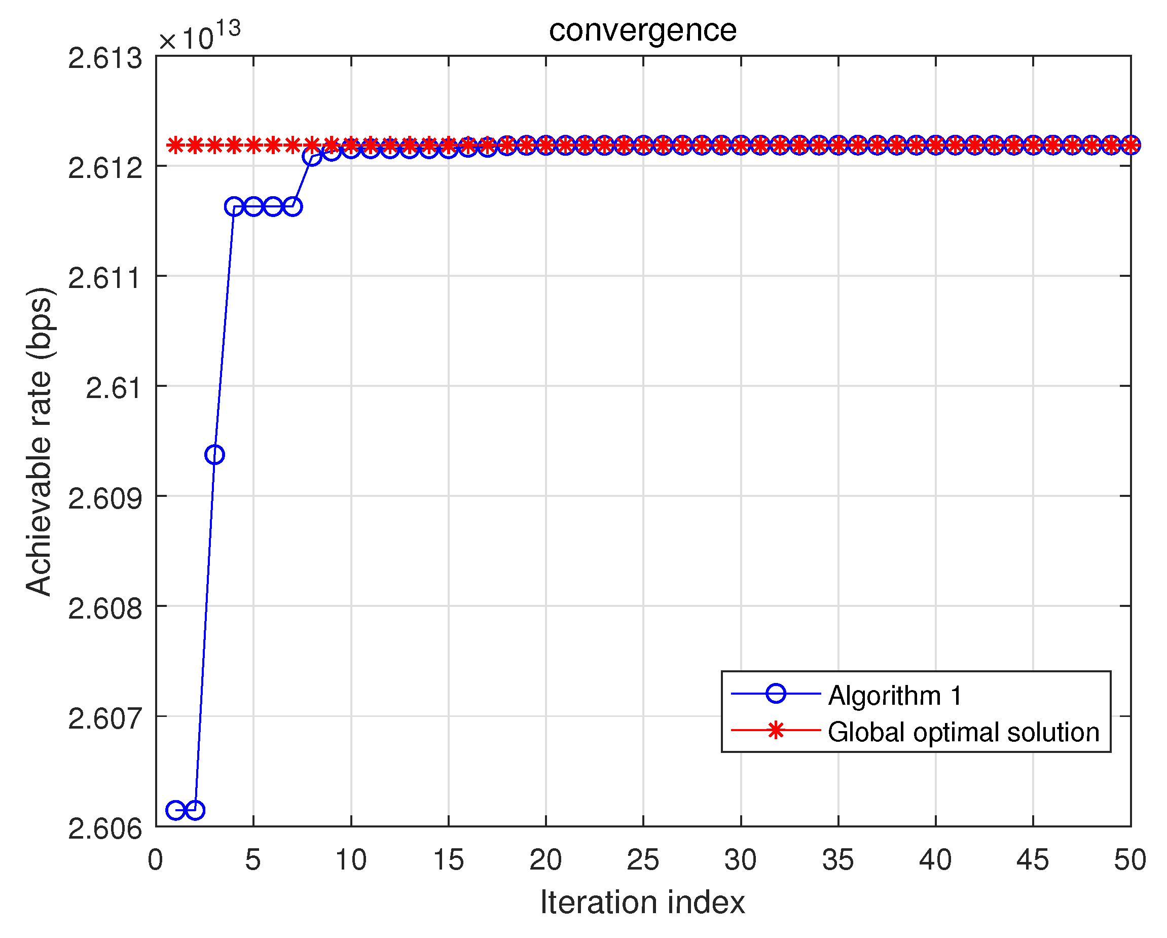
5.2.1. Convergence Analysis

Figure 3 shows the convergence rate of Algorithm 1 and a performance comparison of the proposed method with that of the exhaustive search method. The global optimal solution in Figure 3 ws obtained by the exhaustive search method, which is highly intractable and cannot be used in practice. We found that the PSO algorithm could achieve the global optimal solution after a finite number of iterations from the figure.

5.2.2. Performance Gain of the Optimal Location of RIS versus Randomly Placed RIS for Scenario 1

Figure 4 shows the performance of achievable rate versus the position of the RIS for scenario 1. ( x o p t , z o p t ) is the optimal position calculated by the exhaustive search method. From the figure, we found that the optimal location of the RIS was significantly improved compared with the other RIS positions.
Figure 5a,b verifies the correctness of the algorithm used in the study, where x o p t represents the optimal vertical distance between the RIS and the north wall, and z o p t denotes the optimal vertical distance between the RIS and the floor. In the figures, “no-RIS” means that the received signal was only from the LoS channel; conversely, “RIS-aided” denotes that the received signal contained two parts: LoS and NLoS channels based on the RIS. x o p t in Figure 5a and z o p t in Figure 5b are the results calculated by Algorithm 1. We observed that the solution calculated by Algorithm 1 was the same as that calculated by the exhaustive search method. At the same time, the computational complexity of the PSO algorithm was significantly reduced according to the analysis in Section 4.2. As the objective function in Equation (4) is continuous and differentiable, we found that the location x o p t , y R , z o p t was the optimum location of the RIS in this scenario. Meanwhile, we observed that the position of the RIS could considerably influence the system’s performance from Figure 5a,b. The optimally placed RIS could help the VLC system achieve about 16% improvement in the achievable rate compared with the VLC system without an RIS; with the RIS in the optimal location, superior performance was achieved compared with a randomly placed RIS in the VLC system. This simulation results showed that the PSO algorithm is an appropriate method for solving RIS position problems shaped like scenario 1, showing that research on the optimal location of RISs in VLC systems is important.

5.2.3. Achievable Rate Performance versus Different R m i n for Scenario 2

For scenario 2, different R m i n values mean different constraints, which lead to different optimal positions of the RIS array. According to Equation (5), we can set a proper R m i n to satisfy the QoS and determine the optimal position of the RIS based on different R m i n values (i.e., R m i n is related to an optimal RIS position). Table 2 provides the results for the achievable rate performance for different R m i n values. It can be observed from the table that increasing R m i n results in an improvement in the height of RIS placement z R . However, when R m i n is small (from 0 to 4.10 × 10 12 ), the position of RIS is constant (i.e., the requirement is so small that all the place of the floor can satisfy it). When R m i n is large enough, the optimal position of RIS is not on the wall, and there is no proper position on the wall that satisfies the QoS (i.e., the requirement is high). In the gap between too low and too high, the position changes with the QoS (i.e., R m i n ). Consequently, we chose the optimal position calculated by Algorithm 1 at which to mount the RIS according to the QoS in practice.

6. Conclusions and Future Research Directions

In this paper, we proposed two optimization problems to confirm the optimal position of an RIS for the scenarios that occur in our daily lives. Instead of optimizing the RIS elements’ orientations, we set the position of the RIS array as the optimization variable to achieve the objective function maximization. This is a novel concept, and, to the best of our knowledge, there is little literature in this field. We adopted the particle swarm optimization (PSO) algorithm to solve the problems and confirmed the optimal position of the RIS array. Our simulation results showed that properly designing the position of the RIS array can improve the performance to a greater degree under the condition that the problems are jointly solved with the technology for RIS element orientation. The computational complexity of the PSO algorithm can be significantly reduced to solve position optimization problems compared with that of the exhaustive search method.
The optimization of the RIS position can be regarded as an attractive future research direction. Our proposed method is constrained by the traditional deployment of RISs. Perhaps RISd can be deployed in every position in the room instead of only being mounted on one wall. In other words, it is possible to design a mobile machine on the ceiling to suspend the RIS to change the y R in this study to achieve a greater degree of improvement. Additionally, we only considered an RIS with a single element. In the future, the RIS position can be designed with multiple elements, combined with the assignment scheme of mirrors. The further consideration of optimization algorithms is another direction of our future research work.

Author Contributions

Conceptualization, Q.W.; methodology, J.-N.G.; software, Q.W.; validation, Q.W.; formal analysis, Q.W.; investigation, Q.W.; resources, Q.W.; data curation, J.-N.G.; writing—original draft preparation, Q.W.; writing—review and editing, J.Z.; visualization, Q.W.; supervision, J.Z.; project administration, J.Z.; funding acquisition, J.Z. All authors have read and agreed to the published version of the manuscript.

Funding

This study was supported by the National Natural Science Foundation of China (NSFC) under grant 62071489 and the National Key Research and Development Project (2018YFB1801903).

Conflicts of Interest

The authors declare no conflict of interest.

References

  1. Obeed, M.; Salhab, A.M.; Alouini, M.S.; Zummo, S.A. On optimizing VLC networks for downlink multi-user transmission: A survey. IEEE Commun. Surv. Tutor. 2019, 21, 2947–2976. [Google Scholar] [CrossRef]
  2. Chaaban, A.; Rezki, Z.; Alouini, M.S. On the capacity of intensity-modulation direct-detection Gaussian optical wireless communication channels: A tutorial. IEEE Commun. Surv. Tutor. 2021, 24, 455–491. [Google Scholar] [CrossRef]
  3. Karunatilaka, D.; Zafar, F.; Kalavally, V.; Parthiban, R. LED based indoor visible light communications: State of the art. IEEE Commun. Surv. Tutor. 2015, 17, 1649–1678. [Google Scholar] [CrossRef]
  4. Almadani, Y.; Plets, D.; Bastiaens, S.; Joseph, W.; Ijaz, M.; Ghassemlooy, Z.; Rajbhandari, S. Visible light communications for industrial applications—Challenges and potentials. Electronics 2020, 9, 2157. [Google Scholar] [CrossRef]
  5. ElMossallamy, M.A.; Zhang, H.; Song, L.; Seddik, K.G.; Han, Z.; Li, G.Y. Reconfigurable intelligent surfaces for wireless communications: Principles, challenges, and opportunities. IEEE Trans. Cogn. Commun. Netw. 2020, 6, 990–1002. [Google Scholar] [CrossRef]
  6. Renzo, M.D.; Debbah, M.; Phan-Huy, D.T.; Zappone, A.; Alouini, M.S.; Yuen, C.; Sciancalepore, V.; Alexandropoulos, G.C.; Hoydis, J.; Gacanin, H.; et al. Smart radio environments empowered by reconfigurable AI meta-surfaces: An idea whose time has come. EURASIP J. Wirel. Commun. Netw. 2019, 2019, 129. [Google Scholar] [CrossRef]
  7. Yang, F.; Rahmat-Samii, Y. Surface Electromagnetics: With Applications in Antenna, Microwave, and Optical Engineering; Cambridge University Press: Cambridge, UK, 2019. [Google Scholar]
  8. Oliveri, G.; Rocca, P.; Salucci, M.; Erricolo, D.; Massa, A. Multi-Scale Single-Bit RP-EMS Synthesis for Advanced Propagation Manipulation through System-by-Design. arXiv 2022, arXiv:2203.04399. [Google Scholar] [CrossRef]
  9. Di Renzo, M.; Ntontin, K.; Song, J.; Danufane, F.H.; Qian, X.; Lazarakis, F.; De Rosny, J.; Phan-Huy, D.T.; Simeone, O.; Zhang, R.; et al. Reconfigurable intelligent surfaces vs. relaying: Differences, similarities, and performance comparison. IEEE Open J. Commun. Soc. 2020, 1, 798–807. [Google Scholar] [CrossRef]
  10. Hodge, J.A.; Mishra, K.V.; Zaghloul, A.I. Intelligent time-varying metasurface transceiver for index modulation in 6G wireless networks. IEEE Antennas Wirel. Propag. Lett. 2020, 19, 1891–1895. [Google Scholar] [CrossRef]
  11. Aboagye, S.; Ngatched, T.M.; Dobre, O.A.; Ndjiongue, A.R. Intelligent reflecting surface-aided indoor visible light communication systems. IEEE Commun. Lett. 2021, 25, 3913–3917. [Google Scholar] [CrossRef]
  12. Cao, B.; Chen, M.; Yang, Z.; Zhang, M.; Zhao, J.; Chen, M. Reflecting the light: Energy efficient visible light communication with reconfigurable intelligent surface. In Proceedings of the 2020 IEEE 92nd Vehicular Technology Conference (VTC2020-Fall), Victoria, BC, Canada, 18 November–16 December 2020; pp. 1–5. [Google Scholar]
  13. Qian, L.; Chi, X.; Zhao, L.; Chaaban, A. Secure visible light communications via intelligent reflecting surfaces. In Proceedings of the ICC 2021-IEEE International Conference on Communications, Montreal, QC, Canada, 14–23 June 2021; pp. 1–6. [Google Scholar]
  14. Sun, S.; Yang, F.; Song, J.; Han, Z. Optimization on Multi-User Physical Layer Security of Intelligent Reflecting Surface-Aided VLC. arXiv 2022, arXiv:2201.00705. [Google Scholar]
  15. Wu, Q.; Zhang, J.; Guo, J. Capacity Maximization for Reconfigurable Intelligent Surface-Aided MISO Visible Light Communications. Photonics 2022, 9, 487. [Google Scholar] [CrossRef]
  16. Sun, S.; Yang, F.; Song, J. Sum rate maximization for intelligent reflecting surface-aided visible light communications. IEEE Commun. Lett. 2021, 25, 3619–3623. [Google Scholar] [CrossRef]
  17. Sun, S.; Yang, F.; Song, J.; Han, Z. Joint resource management for intelligent reflecting surface–aided visible light communications. IEEE Trans. Wirel. Commun. 2022, 21, 6508–6522. [Google Scholar] [CrossRef]
  18. Han, Y.; Xiao, Y.; Zhang, X.; Gao, Y.; Zhu, Q.; Dong, B. Design of dynamic active-passive beamforming for reconfigurable intelligent surfaces assisted hybrid VLC/RF communications. IET Commun. 2022, 16, 1531–1544. [Google Scholar] [CrossRef]
  19. Sun, S.; Yang, F.; Song, J.; Zhang, R. Intelligent Reflecting Surface for MIMO VLC: Joint Design of Surface Configuration and Transceiver Signal Processing. arXiv 2022, arXiv:2206.14465. [Google Scholar]
  20. Abdelhady, A.M.; Salem, A.K.S.; Amin, O.; Shihada, B.; Alouini, M.S. Visible light communications via intelligent reflecting surfaces: Metasurfaces vs mirror arrays. IEEE Open J. Commun. Soc. 2020, 2, 1–20. [Google Scholar] [CrossRef]
  21. Ndjiongue, A.R.; Ngatched, T.M.; Dobre, O.A. On the Capacity of RIS-Assisted Intensity-Modulation Optical Channels. IEEE Commun. Lett. 2021, 26, 389–393. [Google Scholar] [CrossRef]
  22. Najafi, M.; Schmauss, B.; Schober, R. Intelligent reflecting surfaces for free space optical communication systems. IEEE Trans. Commun. 2021, 69, 6134–6151. [Google Scholar] [CrossRef]
  23. Ndjiongue, A.R.; Ngatched, T.M.; Dobre, O.A.; Armada, A.G.; Haas, H. Analysis of RIS-based terrestrial-FSO link over GG turbulence with distance and jitter ratios. J. Light. Technol. 2021, 39, 6746–6758. [Google Scholar] [CrossRef]
  24. Benoni, A.; Salucci, M.; Oliveri, G.; Rocca, P.; Li, B.; Massa, A. Planning of EM Skins for Improved Quality-of-Service in Urban Areas. IEEE Trans. Antennas Propag. 2022, 1. [Google Scholar] [CrossRef]
  25. Aboagye, S.; Ndjiongue, A.R.; Ngatched, T.; Dobre, O.; Poor, H.V. RIS-Assisted Visible Light Communication Systems: A Tutorial. arXiv 2022, arXiv:2204.07198. [Google Scholar]
  26. Komine, T.; Nakagawa, M. Fundamental analysis for visible-light communication system using LED lights. Consum. Electron. IEEE Trans. 2004, 50, 100–107. [Google Scholar] [CrossRef]
  27. Tang, T.; Shang, T.; Li, Q. Impact of multiple shadows on visible light communication channel. IEEE Commun. Lett. 2020, 25, 513–517. [Google Scholar] [CrossRef]
  28. Abdelhady, A.M.; Amin, O.; Salem, A.K.S.; Alouini, M.S.; Shihada, B. Channel characterization of IRS-based visible light communication systems. IEEE Trans. Commun. 2022, 70, 1913–1926. [Google Scholar] [CrossRef]
  29. Wang, J.B.; Hu, Q.S.; Wang, J.; Chen, M.; Wang, J.Y. Tight bounds on channel capacity for dimmable visible light communications. J. Light. Technol. 2013, 31, 3771–3779. [Google Scholar] [CrossRef]
  30. Shi, Y.; Eberhart, R.C. Empirical study of particle swarm optimization. In Proceedings of the 1999 Congress on Evolutionary Computation-CEC99 (Cat. No. 99TH8406), Washington, DC, USA, 6–9 July 1999; Volume 3, pp. 1945–1950. [Google Scholar]
Figure 1. Scenario 1: An indoor VLC system contains an AP, a fixed user, and an RIS.
Electronics 11 03076 g001
Figure 2. Scenario 2: An indoor VLC system contains an AP, a mobile user, and an RIS.
Electronics 11 03076 g002
Figure 3. The convergence curve of Algorithm 1 and performance comparison between the proposed and exhaustive search methods.
Electronics 11 03076 g003
Figure 4. Achievable rate versus RIS position.
Electronics 11 03076 g004
Figure 5. (a) Achievable rate on x-axis. (b) Achievable rate on z-axis.
Electronics 11 03076 g005
Table 1. Main simulation parameters.
Name of ParameterValue of Parameter
LED half-power semiangle, Ψ 1 / 2 70
Reflection coefficient, ρ 0.95
Physical area of the PD, A P D 1 cm 2
Length of west wall, x max 5 m
Height of west wall, z max 3 m
Coordinates on Y-axis of RIS, y R 0.1 m
Optical filter gain, T o f 1
Refractive index, a 1.5
Field of view, Φ FoV 70
System bandwidth, B 200 MHz
Photodetector responsiveness of PD, R P D 0.53 A / W
Conversion ration of optical-to-electrical power, q3
Power spectral density of noise, N 10 21 A 2 / Hz
Table 2. Achievable Rate Performance versus different R m i n .
QoSPosition of RISSum Gain of Achievable Rate
R min x R , y R , z R R sum
0 ( 2.5 , 0.1 , 1.39 ) 4.561 × 10 14
4.10 × 10 12 ( 2.5 , 0.1 , 1.39 ) 4.561 × 10 14
4.15 × 10 12 ( 2.5 , 0.1 , 1.43 ) 4.557 × 10 14
4.20 × 10 12 ( 2.5 , 0.1 , 1.48 ) 4.548 × 10 14
4.25 × 10 12 ( 2.5 , 0.1 , 1.52 ) 4.532 × 10 14
4.30 × 10 12 ( 2.5 , 0.1 , 1.56 ) 4.504 × 10 14
4.35 × 10 12 ( 2.5 , 0.1 , 1.62 ) 4.455 × 10 14
4.40 × 10 12 ( 2.5 , 0.1 , 1.73 ) 4.321 × 10 14
4.45 × 10 12 NAN0
Publisher’s Note: MDPI stays neutral with regard to jurisdictional claims in published maps and institutional affiliations.

