
Design a Compact Printed Log-Periodic Biconical Dipole Array Antenna for EMC Measurements


Abstract
:1. Introduction
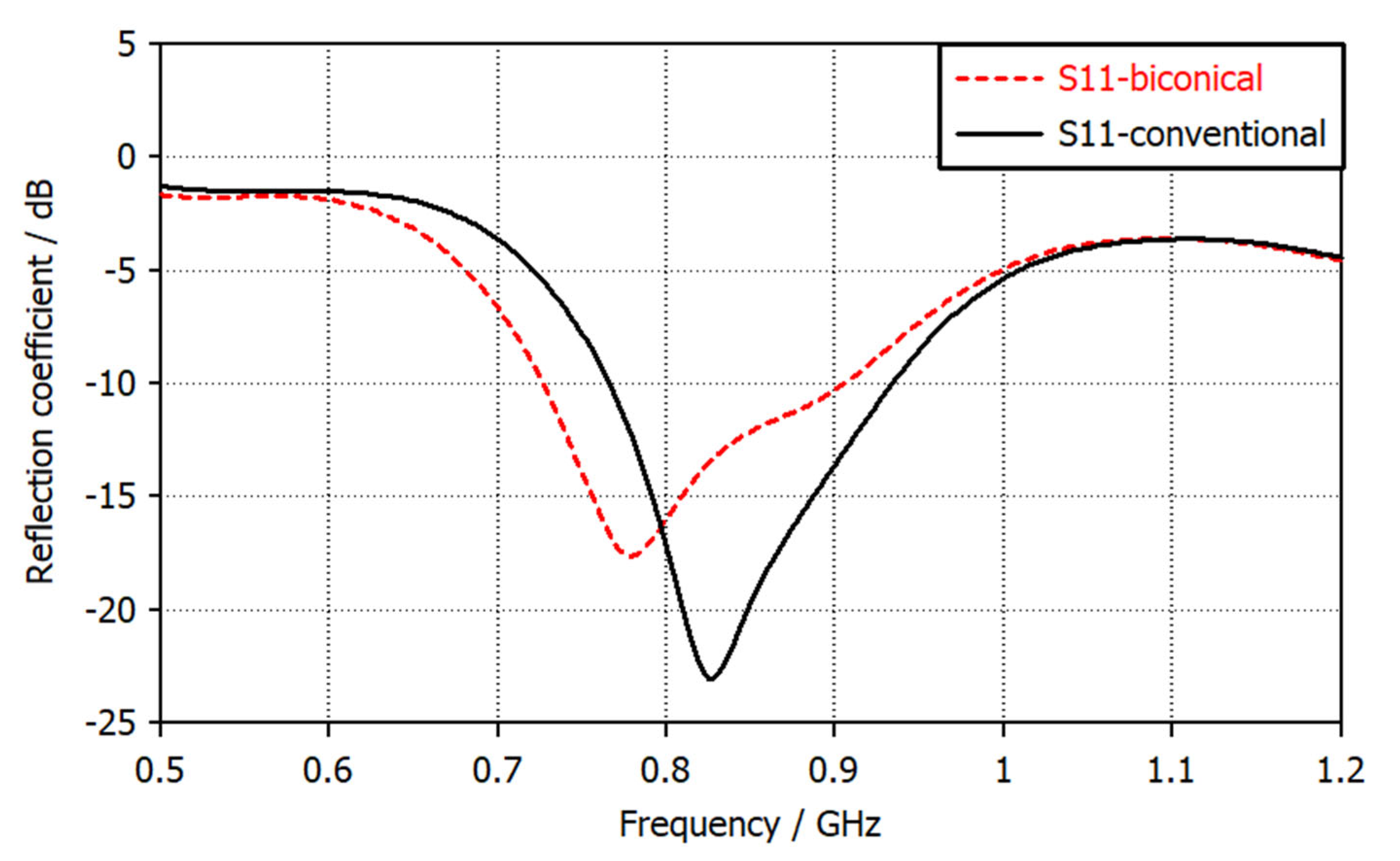
2. Comparative Analysis of Conventional and Biconical Dipoles
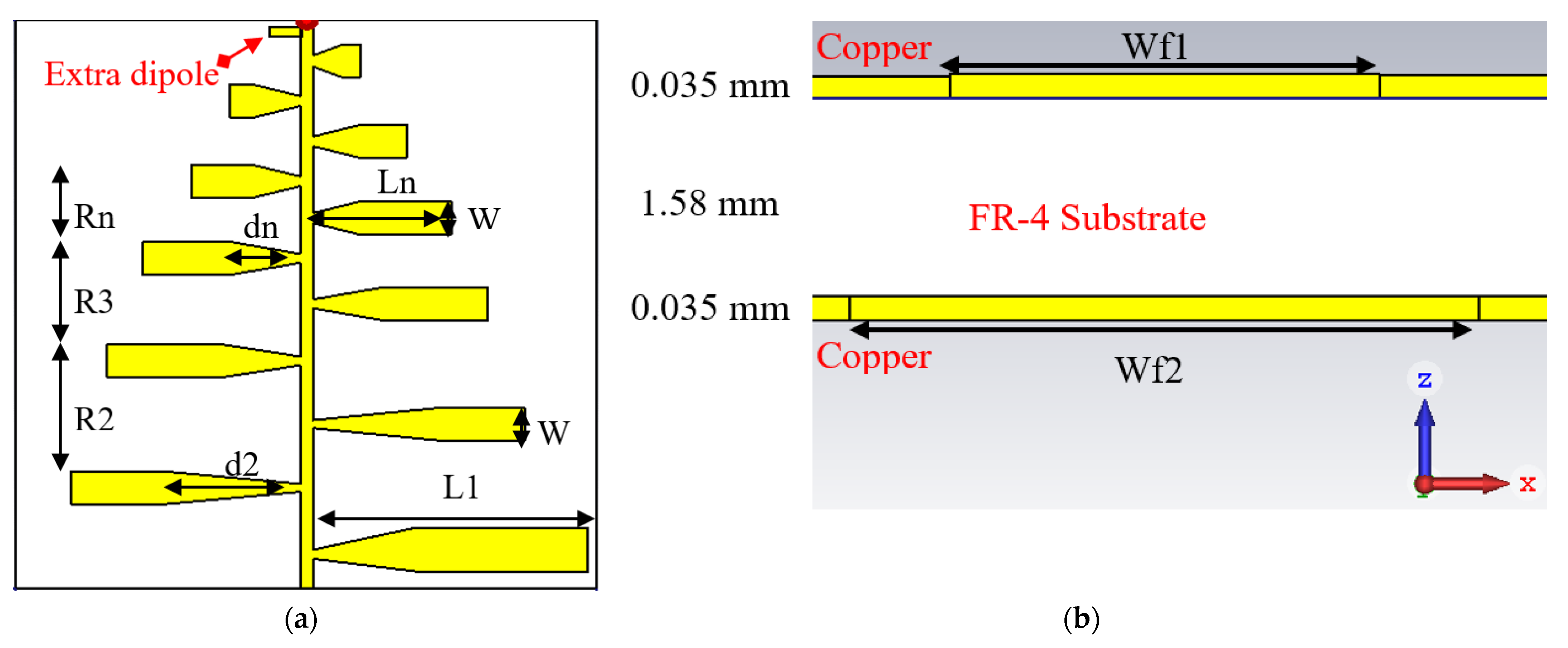
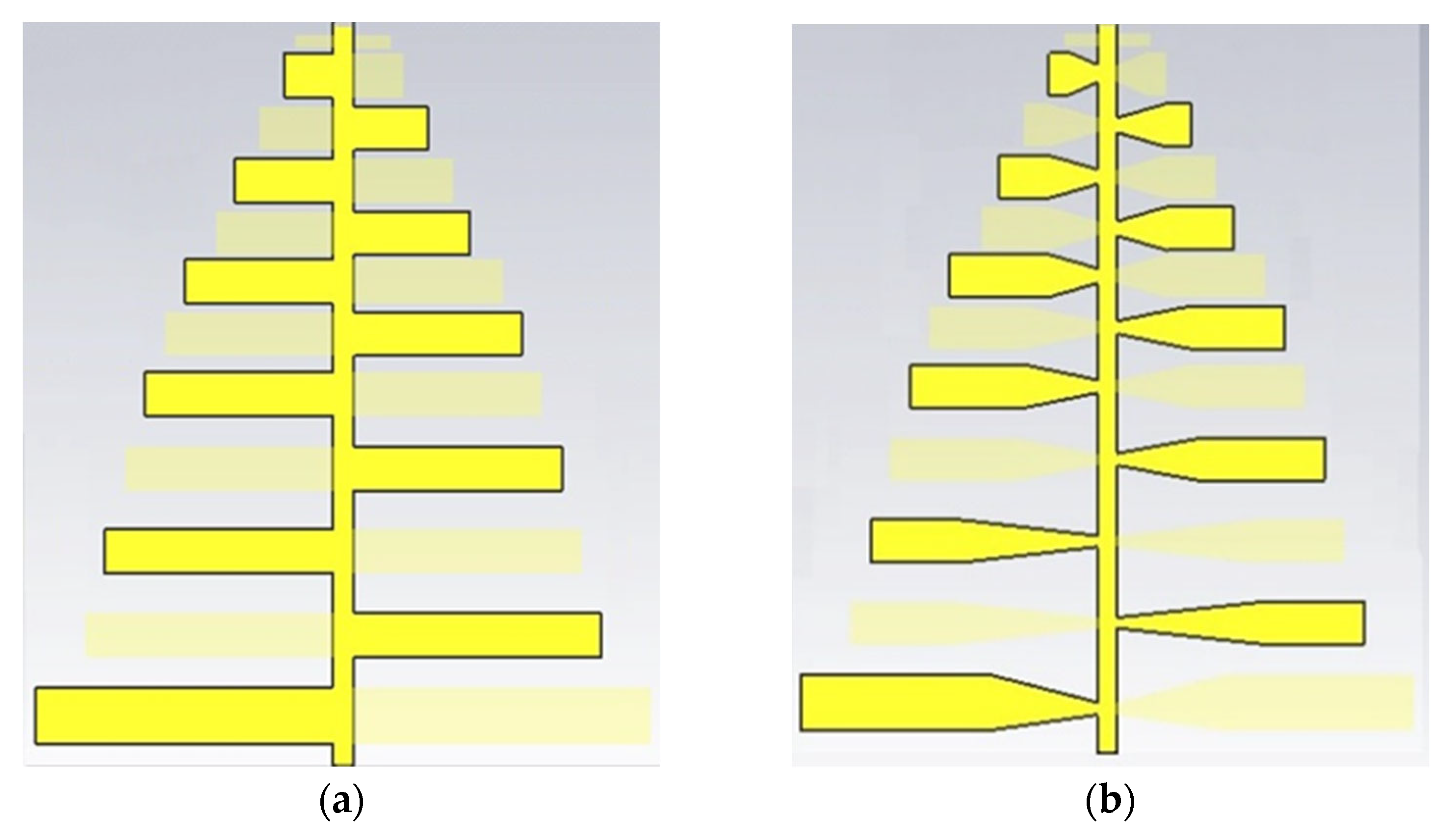
3. Printed Log-Periodic Dipole Array Antenna Design
- According to the desired directivity, scaling factor (τ) and spacing factor (σ) can be evaluated from the point intersection of the straight line σ = 0.243 τ − 0.051.
- Using Equations (2)–(4) to find out the maximum number of dipoles
- 3.
- The length of the most extended dipole (first one), which matches the lowest frequency, can be found from Equation (5).
- 4.
- The distance between each successive dipole can be calculated using Equation (6).
- 5.
- The dipoles’ width can be evaluated using Equations (7) and (8).
- 6.
- Equations (9)–(11) are used to calculate the length, distance, and width of successive dipoles.
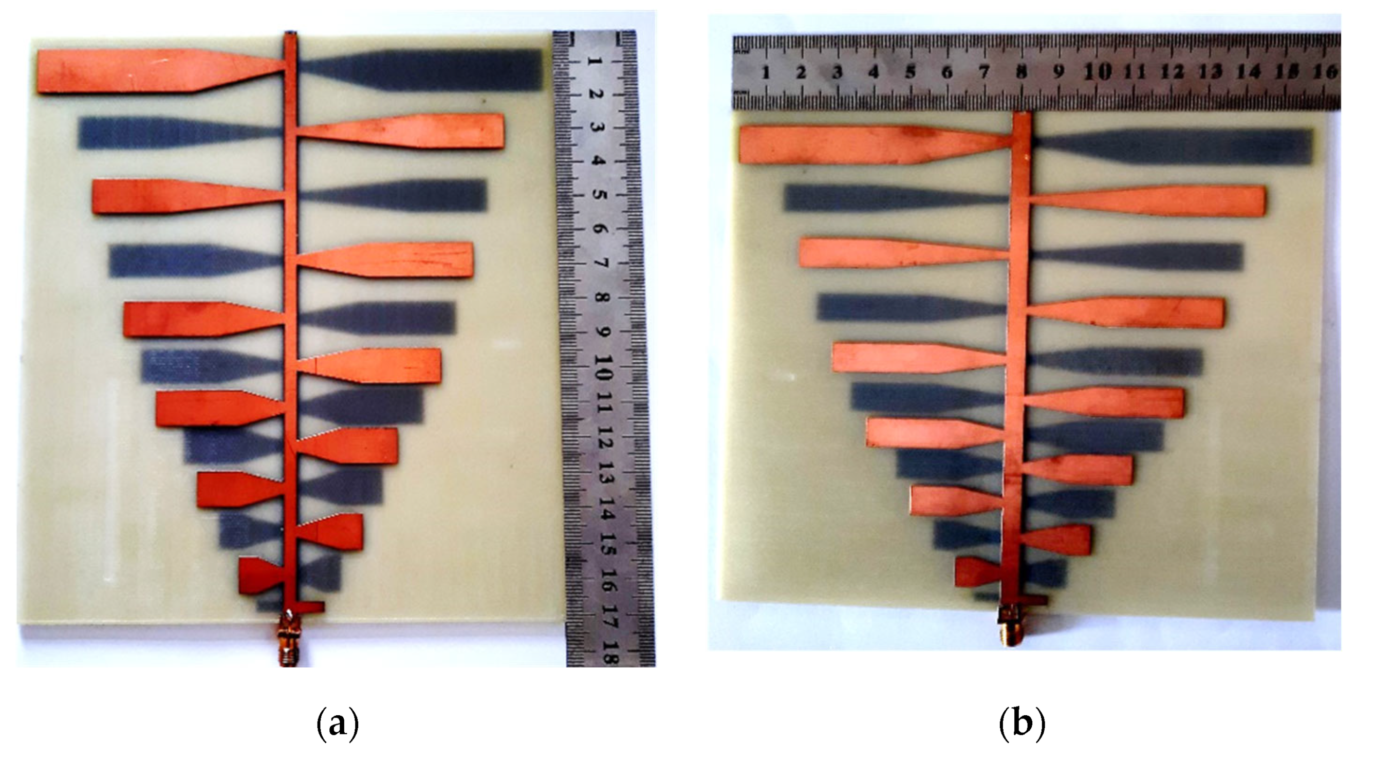
4. Feeding Techniques
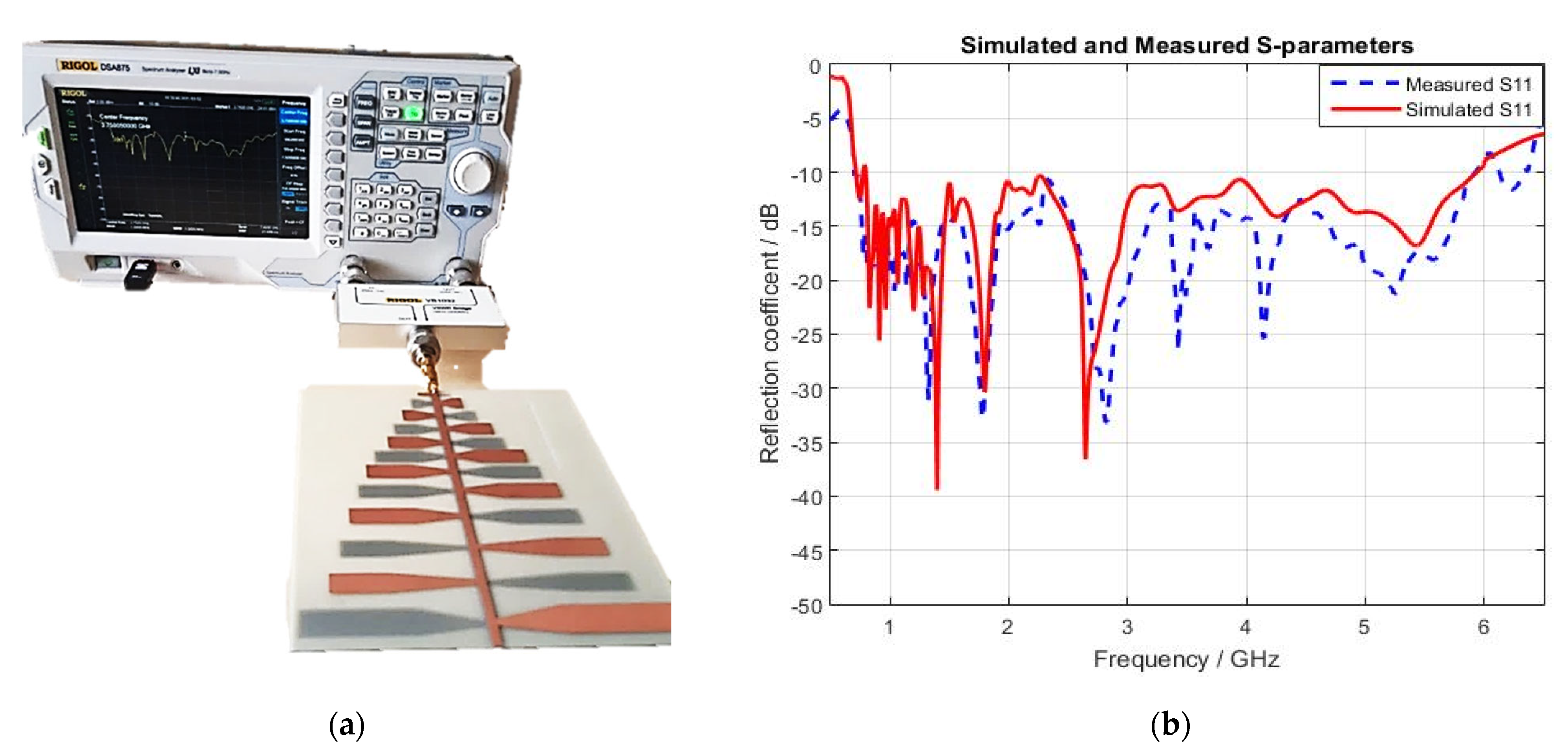
5. Simulation and Measurement Results
5.1. S11-Parameter
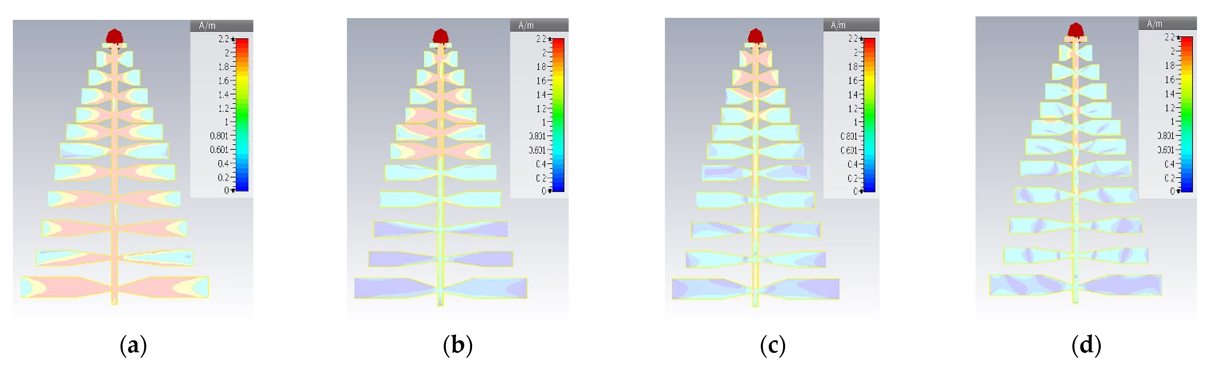
5.2. Surface Current Distribution
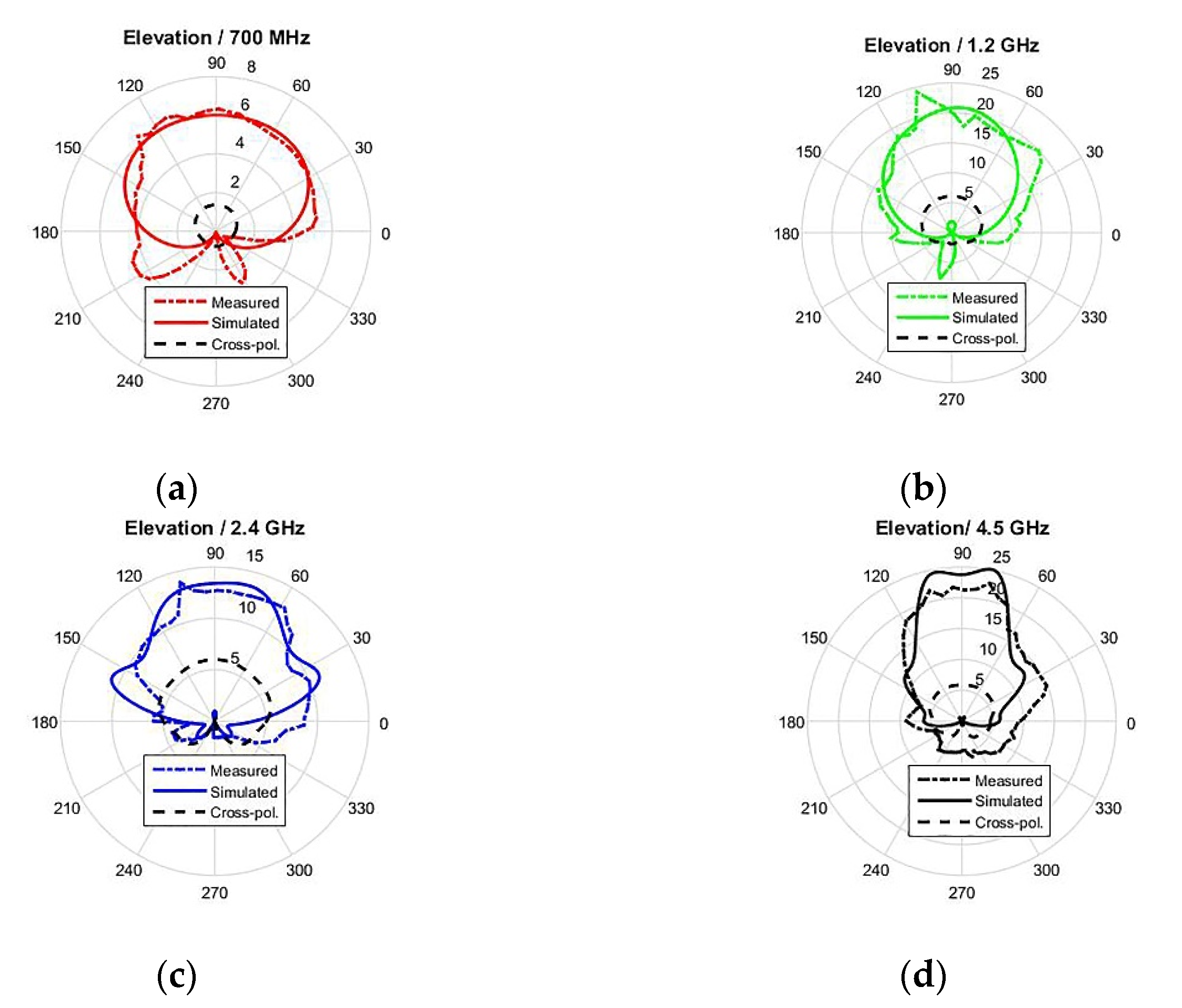
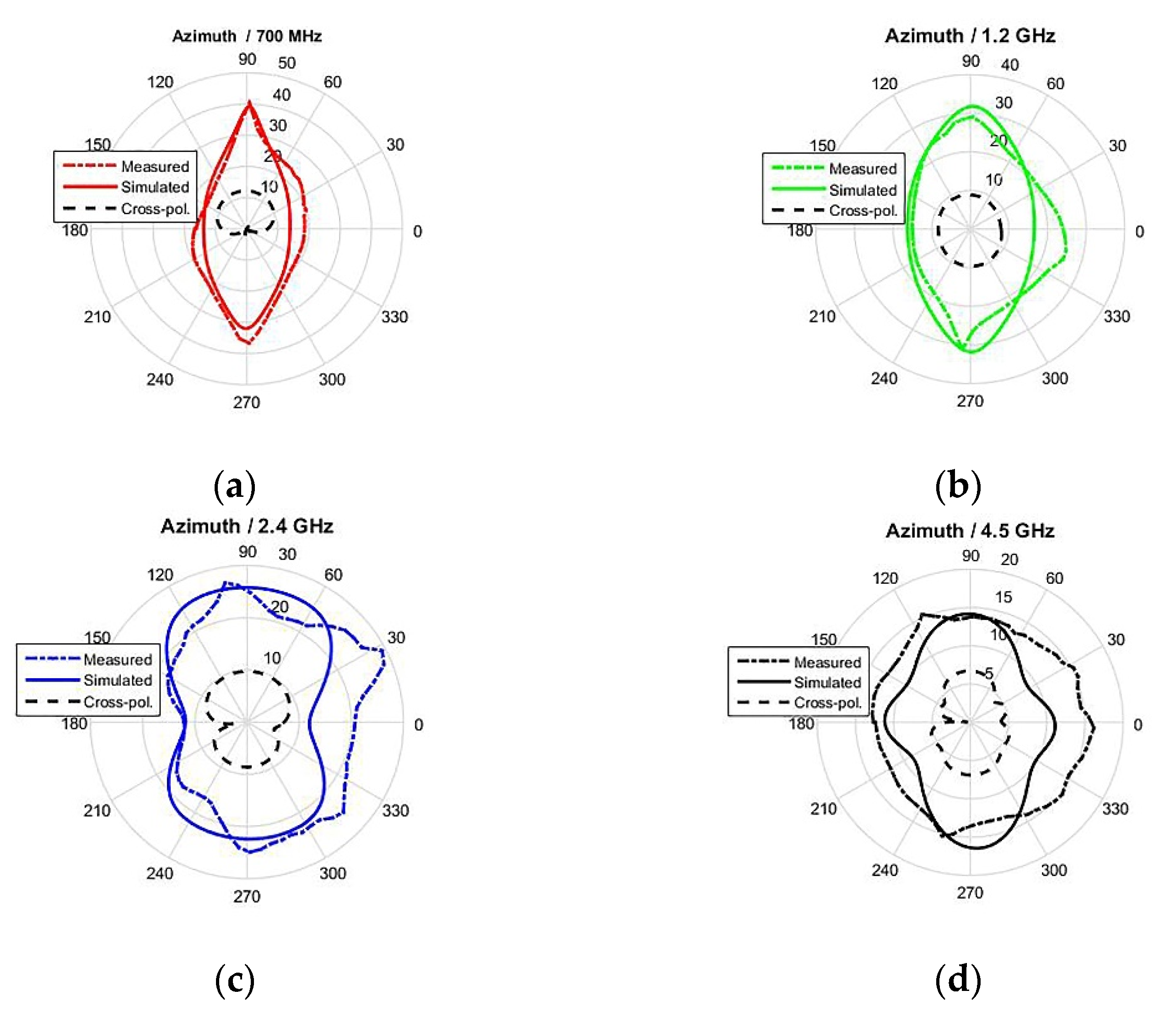
5.3. Radiation Pattern
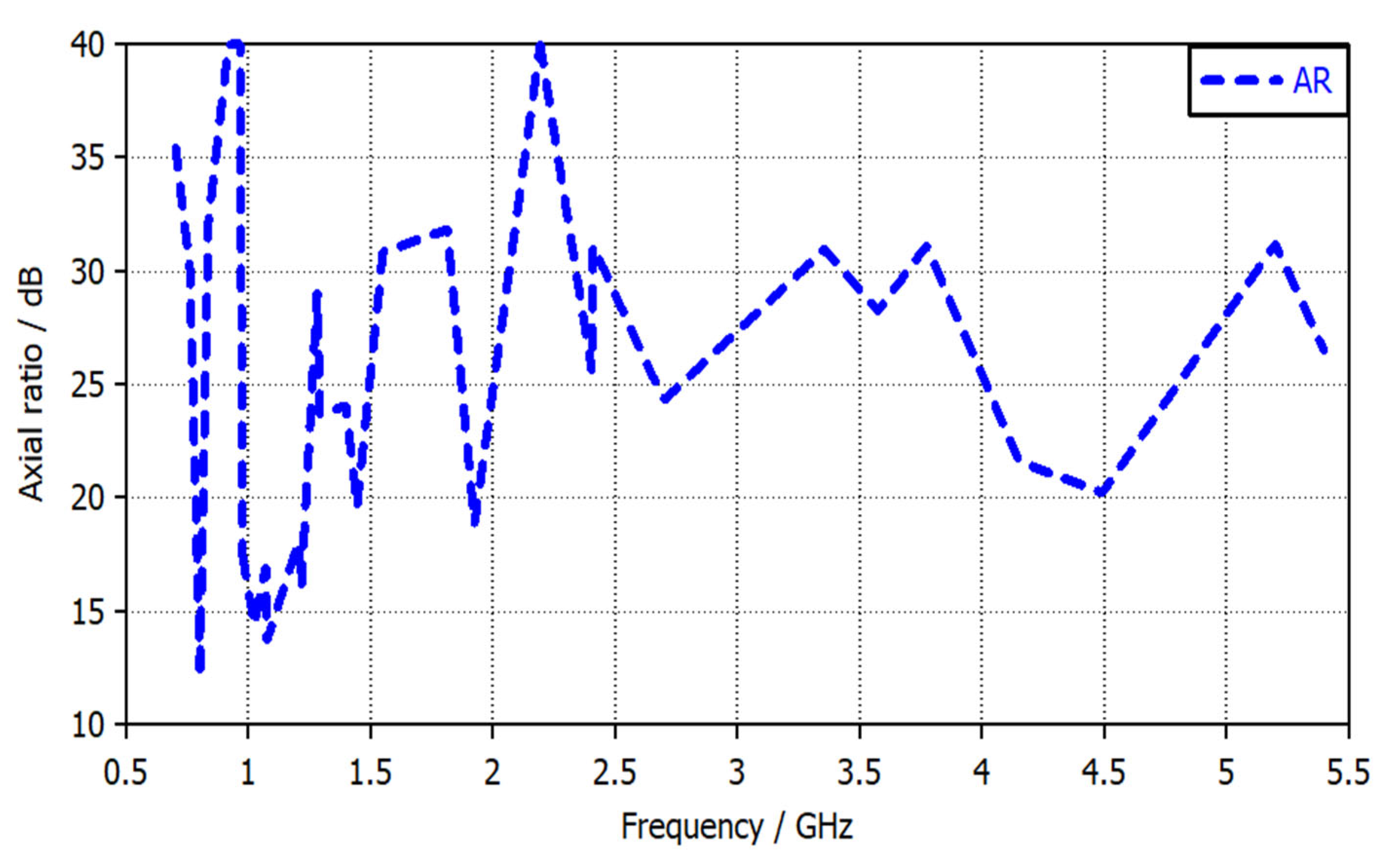
5.4. Axial Ratio, Co and Cross-Polarization
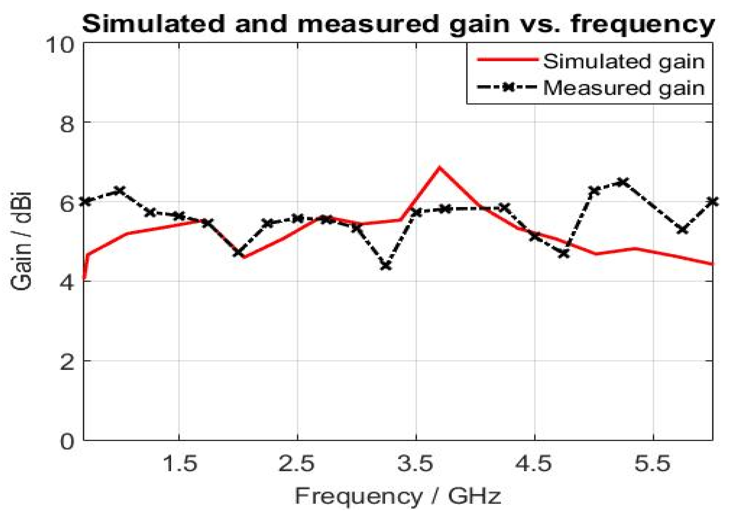
5.5. Realized Gain and Antenna Factor
5.6. Comparison with the Literature Reviewed
5.7. Comparison with the Commercial LPDA Antenna (HyperLOG® 7060)
6. Conclusions
Author Contributions
Funding
Institutional Review Board Statement
Informed Consent Statement
Data Availability Statement
Conflicts of Interest
References
- Abdulhameed, A.A.; Alhamdawee, E.M.; Hayder, I.M. Review of reconfigurable/UWB antenna for interweave cognitive radio applications. Aust. J. Electr. Electron. Eng. 2019, 16, 96–101. [Google Scholar] [CrossRef]
- Bakr, M.S.; Alterkawi, A.B.A.; Gentili, F.; Bosch, W. Reconfigurable ultra-wide-band patch antenna: Cognitive radio. In Proceedings of the 2017 IEEE MTT-S International Microwave Workshop Series on Advanced Materials and Processes for RF and THz Applications (IMWS-AMP), Pavia, Italy, 20–22 September 2017; pp. 1–3. [Google Scholar]
- Al-Yasir, Y.I.A.; Abdulkhaleq, A.M.; Parchin, N.O.; Elfergani, I.T.; Rodriguez, J.; Noras, J.M.; Abd-Alhameed, R.A.; Rayit, A.; Qahwaji, R. Green and Highly Efficient MIMO Transceiver System for 5G Heterogenous Networks. IEEE Trans. Green Commun. Netw. 2022, 6, 500–511. [Google Scholar] [CrossRef]
- Jasim, A.M.; Al-Anbagi, H.N. A comprehensive study of spectrum sensing techniques in cognitive radio networks. In Proceedings of the 2017 International Conference on Current Research in Computer Science and Information Technology (ICCIT), Sulaymaniyah, Iraq, 26–27 April 2017; pp. 107–114. [Google Scholar]
- Al-Anbagi, H.N.; Vertat, I. Cooperative Reception of Multiple Satellite Downlinks. Sensors 2022, 22, 2856. [Google Scholar] [CrossRef] [PubMed]
- Das, A.; Chatterjee, D.; Bhattacharya, A.; Majumder, S.; Chakravarty, D.; Byabarta, N. Comparative study of different techniques to design ultra wideband antenna in cognitive radio. In Proceedings of the 2017 4th International Conference on Opto-Electronics and Applied Optics (Optronix), Kolkata, India, 2–3 November 2017; pp. 1–7. [Google Scholar]
- Mohammed, A.A.; Alnahwi, F.M.; Abdullah, A.S.; Hameed, A.G.A.A. A compact monopole antenna with reconfigurable band notch for underlay cognitive radio applications. In Proceedings of the 2018 International Conference on Advance of Sustainable Engineering and its Application (ICASEA), Wasit-Kut, Iraq, 14–15 March 2018; pp. 25–30. [Google Scholar]
- Abdulhameed, A.A.; Alnahwi, F.M.; Swadi, H.L.; Abdullah, A.S. A compact cognitive radio UWB/reconfigurable antenna system with controllable communicating antenna bandwidth. Aust. J. Electr. Electron. Eng. 2019, 16, 1–11. [Google Scholar] [CrossRef]
- Tu, Y.; Al-Yasir, Y.I.A.; Ojaroudi Parchin, N.; Abdulkhaleq, A.M.; Abd-Alhameed, R.A. A Survey on Reconfigurable Microstrip Filter–Antenna Integration: Recent Developments and Challenges. Electronics 2020, 9, 1249. [Google Scholar] [CrossRef]
- Abdulhameed, A.A.; Alnahwi, F.M.; Al-Anbagi, H.N.; Kubík, Z.; Abdullah, A.S. Frequency reconfigurable key-shape antenna for LTE applications. Aust. J. Electr. Electron. Eng. 2022, 1–9. [Google Scholar] [CrossRef]
- Al-Yasir, Y.I.A.; Ojaroudi Parchin, N.; Tu, Y.; Abdulkhaleq, A.M.; Elfergani, I.T.E.; Rodriguez, J.; Abd-Alhameed, R.A. A Varactor-Based Very Compact Tunable Filter with Wide Tuning Range for 4G and Sub-6 GHz 5G Communications. Sensors 2020, 20, 4538. [Google Scholar] [CrossRef] [PubMed]
- Kubík, Z.; Skála, J. Shielding effectiveness measurement and simulation of small perforated shielding enclosure using FEM. In Proceedings of the 2015 IEEE 15th International Conference on Environment and Electrical Engineering (EEEIC), Rome, Italy, 10–13 June 2015; pp. 1983–1988. [Google Scholar]
- Kim, K.-C.; Choi, B.J.; Jung, S.W.J. Characteristics of the Sleeve Dipole Antenna Used for EMC Applications. IEEE Access 2020, 8, 86957–86961. [Google Scholar] [CrossRef]
- Bang, J.; Han, C.; Jung, K.; Choi, J. High-frequency performance improvement of LPDA for EMC/EMI measurements. In Proceedings of the 2020 International Symposium on Antennas and Propagation (ISAP), Osaka, Japan, 25–28 January 2021; pp. 621–622. [Google Scholar]
- Kawakami, H.; Tanioka, M.; Wakabayashi, R. Circularly polarized log periodic dipole antennas. In Proceedings of the 2020 International Applied Computational Electromagnetics Society Symposium (ACES), Monterey, CA, USA, 27–31 July 2020; pp. 1–2. [Google Scholar]
- Ivšić, B.; Friščić, F.; Dadić, M.; Muha, D. Design and analysis of Vivaldi antenna for measuring electromagnetic compatibility. In Proceedings of the 2019 42nd International Convention on Information and Communication Technology, Electronics and Microelectronics (MIPRO), Opatija, Croatia, 20–24 May 2019; pp. 491–495. [Google Scholar]
- Gerber, M.; Odendaal, J.W.; Joubert, J. DRGH antenna with improved gain and beamwidth performance. IEEE Trans. Antennas Propag. 2019, 68, 4060–4065. [Google Scholar] [CrossRef]
- Jiang, J.; Pan, S.; Wang, S.; Li, G. Miniaturization design of VHF broadband directional radiation TEM horn antenna. In Proceedings of the 2020 International Conference on Microwave and Millimeter Wave Technology (ICMMT), Shanghai, China, 20–23 September 2020; pp. 1–3. [Google Scholar]
- Mallahzadeh, A.; Pazoki, R.; Karimkashi, S. A new UWB skeletal antenna for EMC applications. In Proceedings of the 2007 International Symposium on Microwave, Antenna, Propagation and EMC Technologies for Wireless Communications, Hangzhou, China, 16–17 August 2007; pp. 543–546. [Google Scholar]
- Hacene, Y.; Shuguo, X. Study of a novel ultra-wideband monopole antenna for EMC measurement applications. In Proceedings of the 2012 6th Asia-Pacific Conference on Environmental Electromagnetics (CEEM), Shanghai, China, 6–9 November 2012; pp. 393–395. [Google Scholar]
- Tziris, E.N.; Lazaridis, P.I.; Zaharis, Z.D.; Cosmas, J.P.; Mistry, K.K.; Glover, I.A. Optimized Planar Elliptical Dipole Antenna for UWB EMC Applications. IEEE Trans. Electromagn. Compat. 2019, 61, 1377–1384. [Google Scholar] [CrossRef] [Green Version]
- Kuhn, W.; Peterson, G.; Welch, J. Broadband Antenna Probe for Microwave EMC Measurements. In Proceedings of the 2018 IEEE 27th Conference on Electrical Performance of Electronic Packaging and Systems (EPEPS), San Jose, CA, USA, 14–17 October 2018; pp. 199–201. [Google Scholar]
- Abdulhameed, A.A. Circular slotted monopole printed antenna with grounded stub WLAN band-notch for UWB applications. Aust. J. Electr. Electron. Eng. 2017, 14, 59–63. [Google Scholar] [CrossRef]
- Abdulhameed, A.A.; Kubík, Z. Investigation of Broadband Printed Biconical Antenna with Tapered Balun for EMC Measurements. Energies 2021, 14, 4013. [Google Scholar] [CrossRef]
- Alnahwi, F.M.; Abdulhameed, A.A.; Swadi, H.L.; Abdullah, A.S. A planar integrated UWB/reconfigurable antenna with continuous and wide frequency tuning range for interweave cognitive radio applications. Iran. J. Sci. Technol. Trans. Electr. Eng. 2019, 44, 729–739. [Google Scholar] [CrossRef]
- Casula, G.A.; Maxia, P.; Mazzarella, G.; Montisci, G. Design of a printed log-periodic dipole array for ultra-wideband applications. Prog. Electromagn. Res. C 2013, 38, 15–26. [Google Scholar] [CrossRef]
- Limpiti, T.; Chantaveerod, A.Y. Design of a printed log-periodic dipole antenna (LPDA) for 0.8–2.5 GHz band applications. In Proceedings of the 2016 13th International Conference on Electrical Engineering/Electronics, Computer, Telecommunications and Information Technology (ECTI-CON), Chiang Mai, Thailand, 28 June–1 July 2016; pp. 1–4. [Google Scholar]
- Yu, L.; Chai, S.; Huang, H.; Ding, L.; Xiao, K.; Zhao, F. A printed log-periodic dipole antenna with balanced feed structure. In Proceedings of the 2016 Progress in Electromagnetic Research Symposium (PIERS), Shanghai, China, 8–11 August 2016; pp. 2035–2038. [Google Scholar]
- Kyei, A.; Sim, D.-U.; Jung, Y.-B. Compact log-periodic dipole array antenna with bandwidth-enhancement techniques for the low frequency band. IET Microw. Antennas Propag. 2017, 11, 711–717. [Google Scholar] [CrossRef]
- Anim, K.; Jung, Y.-B. Shortened log-periodic dipole antenna using printed dual-band dipole elements. IEEE Trans. Antennas Propag. 2018, 66, 6762–6771. [Google Scholar] [CrossRef]
- Mistry, K.K.; Lazaridis, P.I.; Zaharis, Z.D.; Xenos, T.D.; Tziris, E.N.; Glover, I.A. An optimal design of printed log-periodic antenna for L-band EMC applications. In Proceedings of the 2018 IEEE International Symposium on Electromagnetic Compatibility and 2018 IEEE Asia-Pacific Symposium on Electromagnetic Compatibility (EMC/APEMC), Suntec City, Singapore, 14–18 May 2018; pp. 1150–1155. [Google Scholar]
- Mistry, K.K.; Lazaridis, P.I.; Ahmed, Q.; Zaharis, Z.D.; Loh, T.H.; Chochliouros, I.P. A printed LPDA antenna with improved low frequency response. In Proceedings of the 2020 XXXIII General Assembly and Scientific Symposium of the International Union of Radio Science, Rome, Italy, 29 August–5 September 2020; pp. 1–4. [Google Scholar]
- Kubacki, R.; Czyżewski, M.; Laskowski, D. Enlarged Frequency Bandwidth of Truncated Log-Periodic Dipole Array Antenna. Electronics 2020, 9, 1300. [Google Scholar] [CrossRef]
- Wu, Q.; Ding, X.; Su, D. A compact dipole antenna with curved reflector for 1.0–4.2 GHz EMC measurement. IEEE Trans. Electromagn. Compat. 2015, 57, 1289–1297. [Google Scholar] [CrossRef]
- CISPR16-1-2; Specification for Radio Disturbance and Immunity Measuring Apparatus and Methods—Part 1–2: Radio Disturbance and Immunity Measuring Apparatus-Ancillary Equipment-Conducted Disturbances. International Electrotechnical Commission: Geneva, Switzerland, 2006.
- Microwave Vision Group. Considerations in EMI Antenna Design. Available online: http://www.interferencetechnology.com/wp-content/uploads/2021/02/Whitepaper-EMC-Considerations-in-EMI-Antenna-Design.pdf (accessed on 8 August 2022).
- Isbell, D. Log periodic dipole arrays. IRE Trans. Antennas Propag. 1960, 8, 260–267. [Google Scholar] [CrossRef]
- DuHamel, R.; Isbell, D. Broadband logarithmically periodic antenna structures. In Proceedings of the 1958 IRE International Convention Record, New York, NY, USA, 21–25 March 1966; pp. 119–128. [Google Scholar]
- Carrel, R. The design of log-periodic dipole antennas. In Proceedings of the 1958 IRE International Convention Record, New York, NY, USA, 21–25 March 1966; pp. 61–75. [Google Scholar]
- Balanis, C.A. Antenna Theory: Analysis and Design; John Wiley & Sons: Hoboken, NJ, USA, 2015. [Google Scholar]
- Dassault Systemes. CST Computer Simulation Technology AG (2016); Dassault Systemes: Darmstadt, Germany, 2014. [Google Scholar]
- Vieira, G.C. Log-Periodic Dipole Antennas in Printed Circuit Technology; Instituto Superior Tecnico: Lisboa, Portugal, 2018. [Google Scholar]
- Alexander, M.; Salter, M.; Gentle, D.; Knight, D.; Loader, B.; Holland, K. Calibration and Use of Antennas, Focusing on EMC Applications; National Physical Laboratory: Teddington, UK, 2004. [Google Scholar]
- Patre, S.R.; Singh, S.; Singh, S.P. Effect of dielectric substrate on performance of planar trapezoidal toothed log-periodic antenna. In Proceedings of the 2013 Students Conference on Engineering and Systems (SCES), Allahabad, India, 12–14 April 2013; pp. 1–4. [Google Scholar]
- Kim, J.I.; Safaai-Jazi, A.J. Log-periodic loop antennas with high gain and linear polarization. Microw. Opt. Technol. Lett. 2000, 27, 66–68. [Google Scholar] [CrossRef]
- McLean, J.; Sutton, R.; Hoffman, R.J. Interpreting Antenna Performance Parameters for EMC Applications: Part 3: Antenna Factor; TDK RF Solutions Inc.: Cedar Park, TX, USA, 2004. [Google Scholar]
- Shop, A. HyperLOG® 7060. Available online: https://aaronia-shop.com/products/broadband-antenna-hyperlog7060 (accessed on 8 August 2022).


| No. | 1 | 2 | 3 | 4 | 5 | 6 | 7 | 8 | 9 | 10 | 11 | 12 |
|---|---|---|---|---|---|---|---|---|---|---|---|---|
| L (mm) | 77.5 | 65 | 60 | 55 | 50 | 45 | 40 | 31.8 | 27.5 | 21.2 | 15 | 10 |
| W (mm) | 13 | 10 | 10 | 10 | 10 | 10 | 10 | 10 | 10 | 10 | 10 | 5 |
| R (mm) | 20 | 19 | 19 | 17 | 13.7 | 12 | 12 | 12 | 12 | 12 | 12 | -- |
| d (mm) | 20 | 30 | 27.5 | 13.75 | 11.25 | 11.25 | 11.25 | 5 | 5 | 5 | 5 | -- |
| Freq./GHz | 0.7 | 1 | 1.5 | 2 | 2.5 | 3 | 3.5 | 4 | 4.5 | 5 | 5.5 | 6 |
|---|---|---|---|---|---|---|---|---|---|---|---|---|
| AF/dBm−1 | 18 | 24.5 | 28.1 | 31.5 | 32.9 | 34.3 | 35.1 | 36.2 | 37.7 | 39.5 | 39.5 | 41.1 |
| AG/dBi | 7 | 5.7 | 5.6 | 4.7 | 5.2 | 5.4 | 6 | 6 | 5.5 | 4.7 | 5.4 | 4.6 |
| Rf. | [27] | [28] | [29] | [30] | [31] | [32] | Our Work |
|---|---|---|---|---|---|---|---|
| Freq./GHz | (0.8–2.5) | (0.5–3) | (0.55–9) | (0.5–10) | (0.8–2.3) | (0.4–8) | (0.5–6) |
| FBW | 103% | 143% | 177% | 181% | 96.7% | 180% | 170% |
| 4.3 | 4.3 | 3.5 | 3.5 | 4.3 | 4.3 | 4.3 | |
| 0.78 | 0.86 | 0.93 | 0.91 | 0.86 | 0.9 | 0.86 | |
| Gain/dBi | 6.5 | 7–7.5 | 2.4–7.8 | 3–6 | 4.5–6.3 | 2.5–6.9 | 4.6–7 |
| No.of dipoles | 12 | 12 | 48 | 25 | 12 | 25 | 12 |
| Size/λo | 0.426 × 0.4 | 0.44 × 0.25 | 0.49 × 0.35 | 0.36 × 0.43 | 0.426 × 0.37 | 0.36 × 0.37 | 0.28 × 0.26 |
| Feeding | Typical | Balanced | Typical | Typical | Optimized | Typical | Balanced |
| Application | EMC | EMC | EMC | EMC | EMC | EMC | EMC |
| Ref. | Size Reduction | Miniaturization Technique |
|---|---|---|
| [29] | 27% and 20% | Using Hat loading and Top loading |
| [30] | 40% | Using Dual-band dipoles |
| This work | 50% and 50% | Using biconical dipoles |
| Specifications | HyperLOG® 7060 | Proposed Design |
|---|---|---|
| Dimensions/mm | 340 × 200 × 25 | 170 × 160 × 1.6 |
| Design | Logarithmic-periodic | Logarithmic-periodic |
| Substrate | - | FR-4 |
| Weight/g | 250 | 70 |
| Gain/dBi | 3.1–5.5 | 4.6–7 |
| Frequency range/MHz | 700–6000 | 500–6000 |
| Antenna Factor *(1)/dBm−1 | 26–41 | 24.5–41.18 |
| RF Connector Picture | SMA Female | SMA Female |
| Freq./GHz | AF [29] | AF [30] | AF [32] | Proposed Design | AF [HyperLOG 7060] [47] |
|---|---|---|---|---|---|
| 0.5 | 20 | 20 | 22 | 18.1 | -- |
| 1 | 23 | 25.5 | 29.5 | 24.5 | 26 |
| 1.5 | 27 | 28.5 | 30 | 28.1 | 29 |
| 2 | 30 | 31.5 | 30.5 | 31.5 | 31.5 |
| 2.5 | 32 | 33.5 | 32 | 32.9 | 33 |
| 3 | 34 | 36 | 34 | 34.3 | 35 |
| 3.5 | 35 | 37.5 | 35 | 35.1 | 36.5 |
| 4 | 36 | 39 | 36.5 | 36.2 | 37.25 |
| 4.5 | 37 | 40 | 37 | 37.78 | 37.75 |
| 5 | 37.9 | 41 | 38 | 39.5 | 38.5 |
| 5.5 | 39 | 41.5 | 38.5 | 39.54 | 40.5 |
| 6 | 40 | 42 | 40 | 41.18 | 41 |
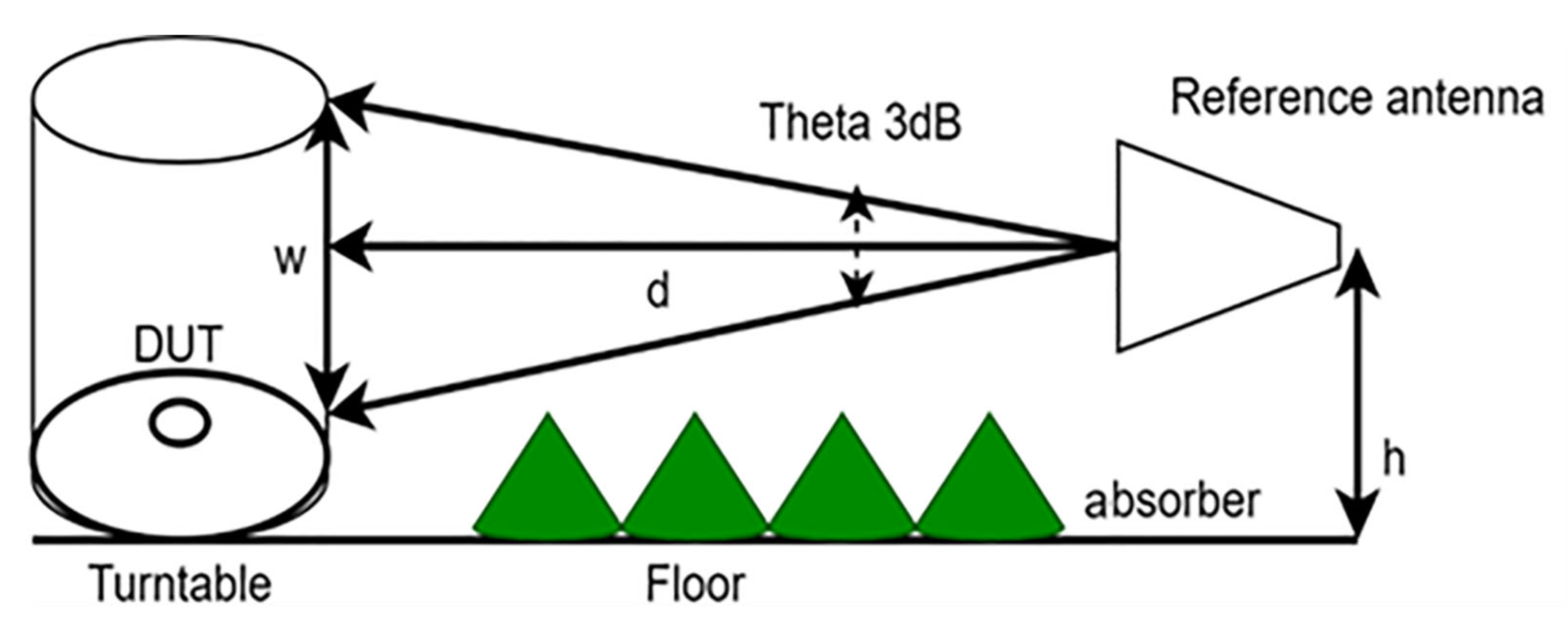
| Frequency/GHz | CISPR 16.1.2/° | w of CISPR 16.1.2/m | Proposed Design/° | w of Proposed Design |
|---|---|---|---|---|
| 1 | 60 | 1.15 | 112 | 2.95 |
| 2 | 55 | 1.04 | 141 | 4.28 |
| 4 | 55 | 1.04 | 55 | 1.04 |
| 6 | 55 | 1.04 | 46.4 | 0.85 |
Publisher’s Note: MDPI stays neutral with regard to jurisdictional claims in published maps and institutional affiliations. |
© 2022 by the authors. Licensee MDPI, Basel, Switzerland. This article is an open access article distributed under the terms and conditions of the Creative Commons Attribution (CC BY) license (https://creativecommons.org/licenses/by/4.0/).
Share and Cite
Abdulhameed, A.A.; Kubík, Z. Design a Compact Printed Log-Periodic Biconical Dipole Array Antenna for EMC Measurements. Electronics 2022, 11, 2877. https://doi.org/10.3390/electronics11182877
Abdulhameed AA, Kubík Z. Design a Compact Printed Log-Periodic Biconical Dipole Array Antenna for EMC Measurements. Electronics. 2022; 11(18):2877. https://doi.org/10.3390/electronics11182877
Chicago/Turabian StyleAbdulhameed, Abdulghafor A., and Zdeněk Kubík. 2022. "Design a Compact Printed Log-Periodic Biconical Dipole Array Antenna for EMC Measurements" Electronics 11, no. 18: 2877. https://doi.org/10.3390/electronics11182877
APA StyleAbdulhameed, A. A., & Kubík, Z. (2022). Design a Compact Printed Log-Periodic Biconical Dipole Array Antenna for EMC Measurements. Electronics, 11(18), 2877. https://doi.org/10.3390/electronics11182877