
A Miniaturized Triple-Band Antenna Based on Square Split Ring for IoT Applications

 ,
,  , ,
, ,  and
and 
Abstract
:1. Introduction
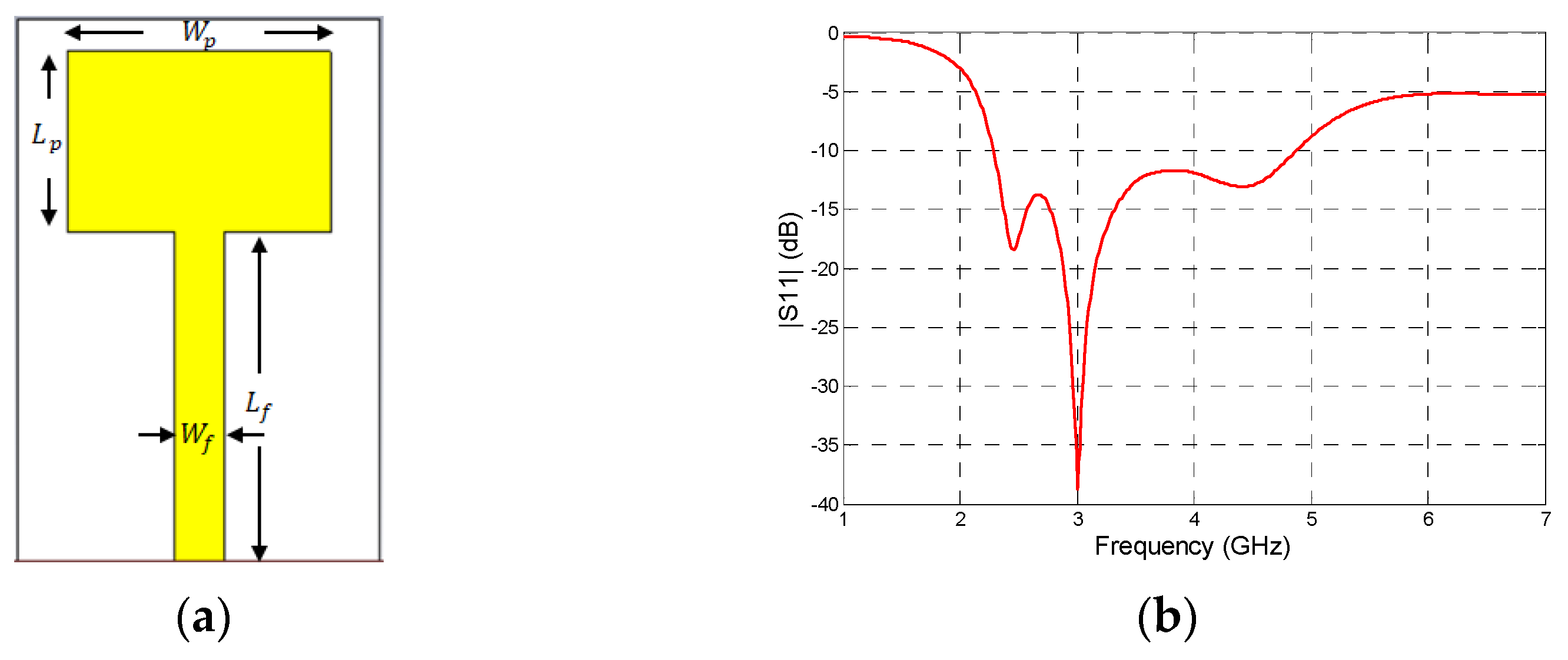
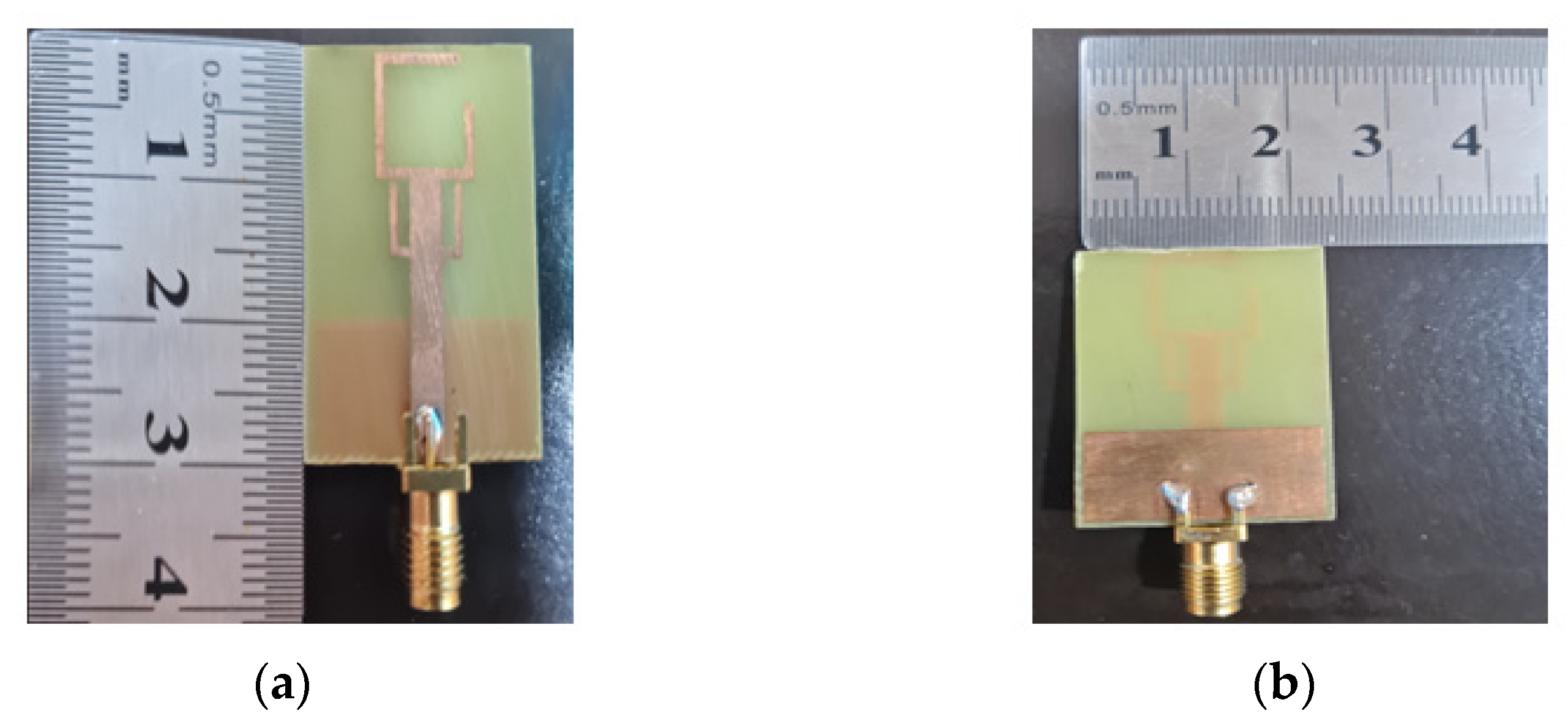
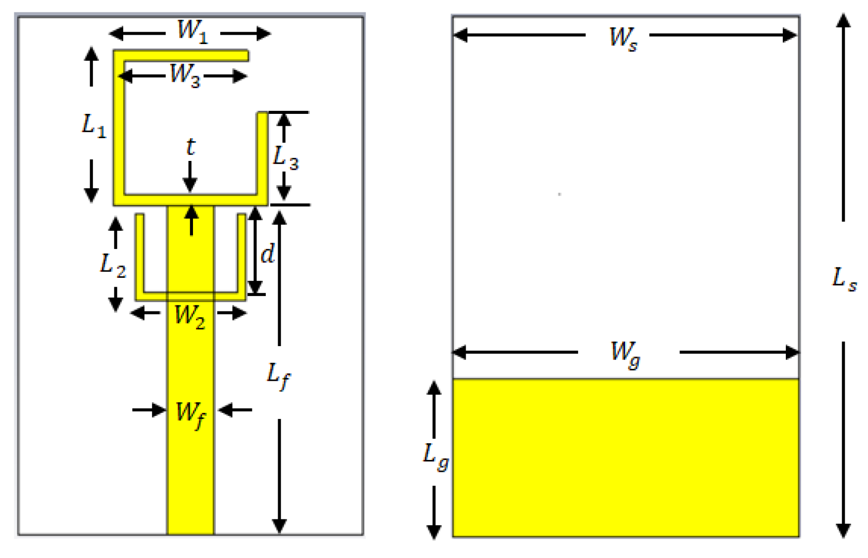
2. Antenna Design
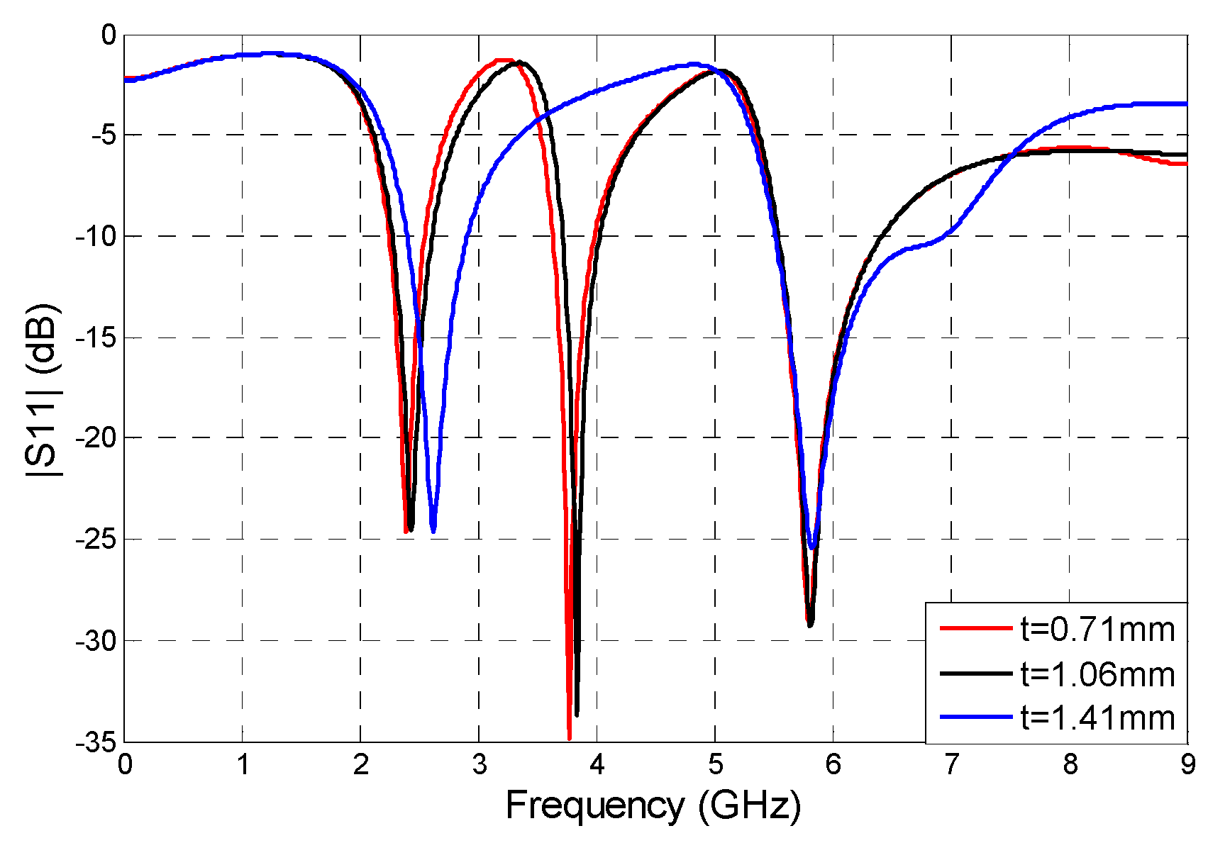
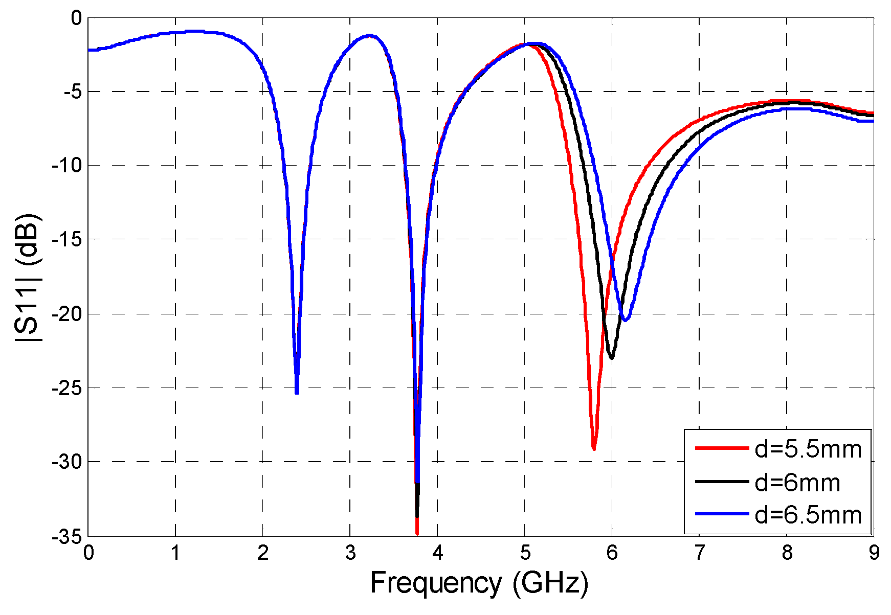
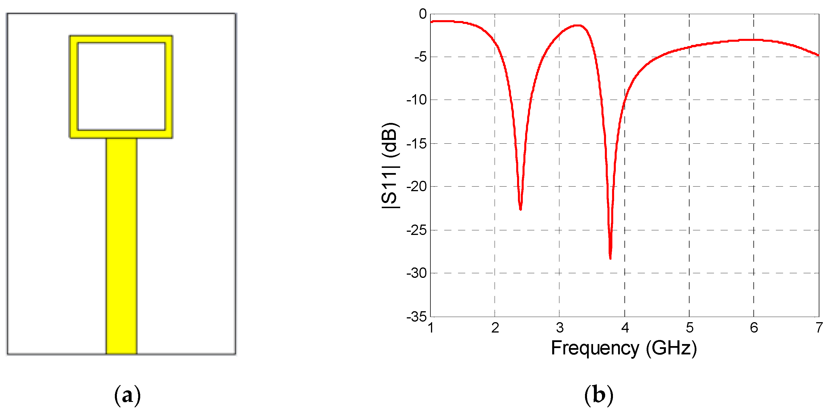
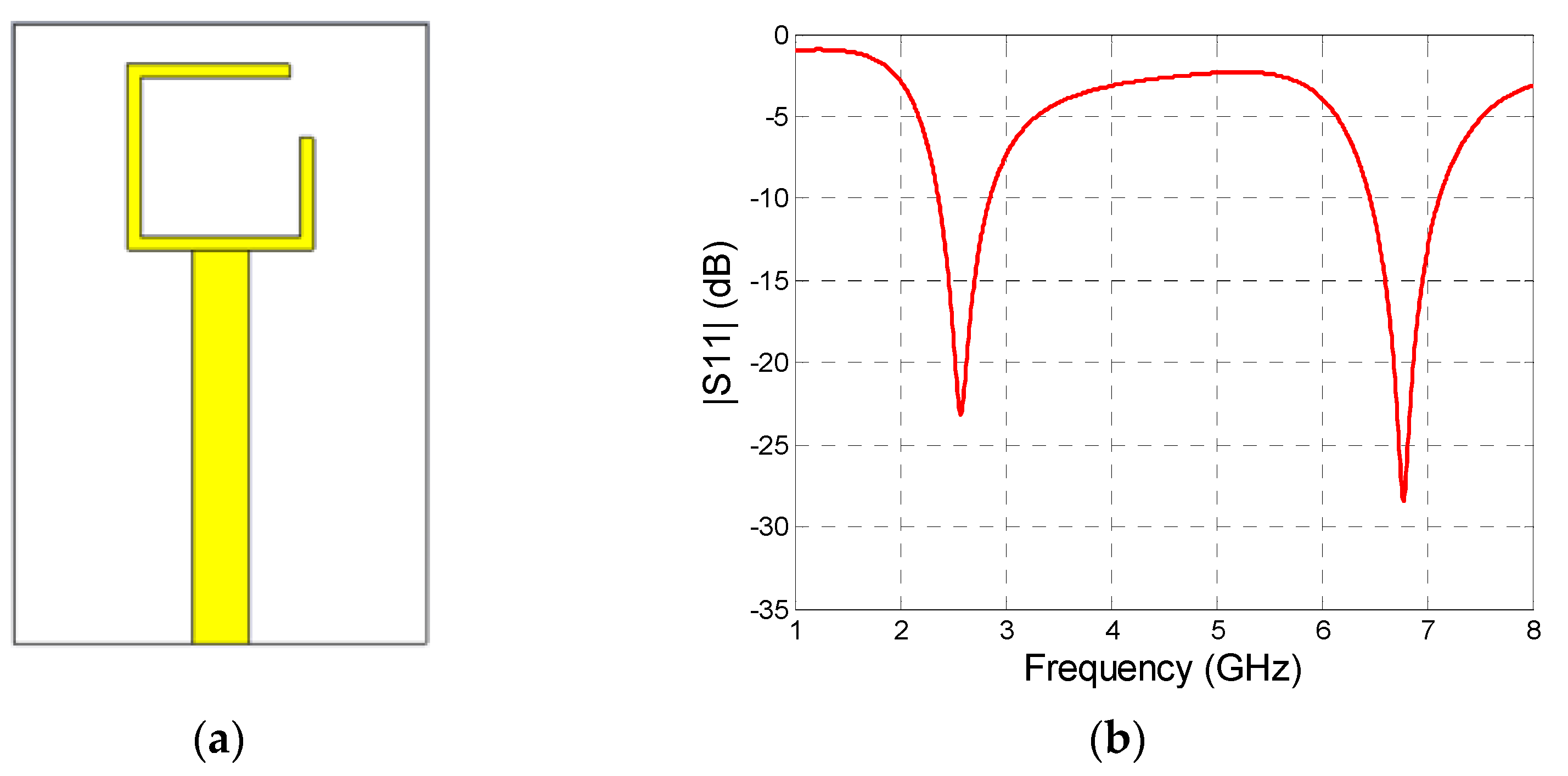
3. Parametric Study
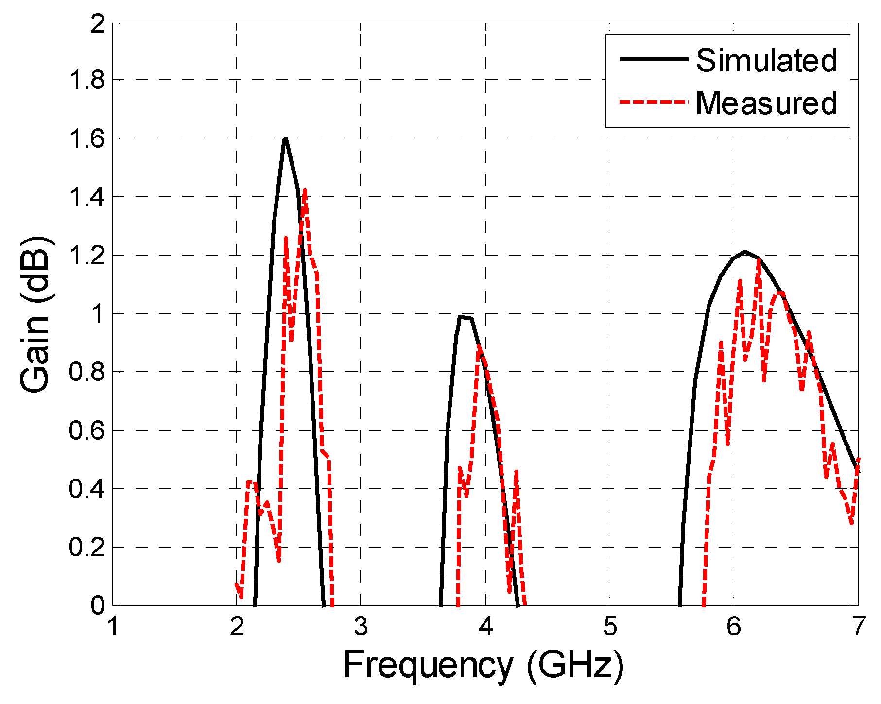
4. Results
5. Conclusions
Author Contributions
Funding
Data Availability Statement
Conflicts of Interest
References
- Xu, K.D.; Zhang, Y.H.; Spiegel, R.J.; Fan, Y.; Joines, W.T.; Liu, Q.H. Design of a Stub-Loaded Ring-Resonator Slot for Antenna Application. IEEE Trans. Antennas Propag. 2015, 63, 517–524. [Google Scholar] [CrossRef]
- Al-Fuqaha, A.; Guizani, M.; Mohammadi, M.; Aledhari, M.; Ayyash, M. Internet of things: A survey on enabling technologies, protocols, and applications. IEEE Commun. Surv. Tutor. 2015, 17, 2347–2376. [Google Scholar] [CrossRef]
- Mao, Y.; Guo, S.; Chen, M. Compact dual-band monopole antenna with defected ground plane for Internet of things. IET Microw. Antennas Propag. 2018, 12, 1332–1338. [Google Scholar] [CrossRef]
- Vijayvergiya, P.L.; Panigrahi, R.K. Single-layer single-patch dual band antenna for satellite applications. IET Microw. Antennas Propag. 2017, 11, 664–669. [Google Scholar] [CrossRef]
- Liu, H.-W.; Wen, P.; Zhu, S.-S.; Ren, B.; Guan, X.; Yu, H. Quad-band CPW-fed monopole antenna based on flexible pentangle-loop radiator. IEEE Antennas Wirel. Propag. Lett. 2015, 14, 1373–1376. [Google Scholar] [CrossRef]
- Alnahwi, F.M.; Al-Yasir, Y.I.; See, C.H.; Abd-Alhameed, R.A. Single-Element and MIMO Circularly Polarized Microstrip Antennas with Negligible Back Radiation for 5G Mid-Band Handsets. Sensors 2022, 22, 3067. [Google Scholar] [CrossRef] [PubMed]
- Mandal, D.; Pattnaik, S.S. Quad-band wearable slot antenna with Low SAR values for 1.8 GHz DCS, 2.4 GHz WLAN and 3.6/5.5 GHz WiMAX Applications. Prog. Electromagn. Res. B. 2018, 81, 163–182. [Google Scholar] [CrossRef]
- Du, Y.Y.; Zhao, A.P. An internal quad-band printed monopole antenna for oval-shaped mobile terminals. IEEE Trans. Mag. 2012, 48, 683–686. [Google Scholar] [CrossRef]
- Chen, C.-C.; Sim, C.-Y.-D.; Chen, F.-S. A novel compact quad-band narrow strip-loaded printed monopole antenna. IEEE Antennas Wirel. Propag. Lett. 2009, 8, 974–976. [Google Scholar] [CrossRef]
- Abdalla, M.A.; Hu, Z. Design and analysis of a compact quad band loaded monopole antenna with independent resonators. Int. J. Microw. Wirel. Technol. 2018, 10, 479–486. [Google Scholar] [CrossRef]
- Cao, Y.F.; Cheung, S.W.; Yuk, T.I. A multiband slot antenna for GPS/WiMAX/WLAN systems. IEEE Trans. Antennas Propag. 2015, 63, 952–958. [Google Scholar] [CrossRef]
- Bilotti, F.; Alu, A.; Vegni, L. Design of miniaturized metamaterial patch antennas with mu-negative loading. IEEE Trans. Antennas Propag. 2008, 56, 1640–1647. [Google Scholar] [CrossRef]
- Ullah, M.H.; Islam, M.T.; Mandeep, J.S. A parametric study of high dielectric material substrate for small antenna design. Int. J. Appl. Electromagn. Mech. 2013, 41, 193–198. [Google Scholar] [CrossRef]
- Alnahwi, F.; Abdalhameed, A.; Swadi, H.L.; Abdullah, A.S. A compact wide-slot UWB antenna with reconfigurable and sharp dual-band notches for underlay cognitive radio applications. Turk. J. Electr. Eng. Comput. Sci. 2019, 27, 94–105. [Google Scholar] [CrossRef]
- Yadav, N.P. Triple u-slot loaded defected ground plane antenna for multiband operations. Microw. Opt. Technol. Lett. 2016, 58, 124–128. [Google Scholar] [CrossRef]
- Jha, K.R.; Bukhari, B.; Singh, C.; Mishra, G.; Sharma, S.K. Compact Planar Multistandard MIMO Antenna for IoT Applications. IEEE Trans. Antennas Propag. 2018, 66, 3327–3336. [Google Scholar] [CrossRef]
- Saghati, A.P.; Azarmanesh, M.; Zaker, R.A. Novel Switchable Single- and Multifrequency Triple-Slot Antenna for 2.4-GHz Bluetooth, 3.5-GHz WiMax, and 5.8-GHz WLAN. IEEE Antennas Wirel. Propag. Lett. 2010, 9, 534–537. [Google Scholar] [CrossRef]
- Bashir, U.; Jha, K.R.; Mishra, G.; Singh, G.; Sharma, S.K. Octahedron-Shaped Linearly Polarized Antenna for Multistandard Services Including RFID and IoT. IEEE Trans. Antennas Propag. 2017, 65, 3364–3373. [Google Scholar] [CrossRef]
- Kulkarni, J. Multi-band printed monopole antenna conforming bandwidth requirement of GSM/WLAN/WiMAX standards. Prog. Electromagn. Res. Lett. 2020, 91, 59–66. [Google Scholar] [CrossRef]
- Alici, K.B.; Serebryannikov, A.E.; Ozbay, E. Radiation properties and coupling analysis of a metamaterial based, dual polarization, dual band, multiple split ring resonator antenna. J. Electromagn. Waves Appl. 2010, 24, 1183–1193. [Google Scholar] [CrossRef]
- Malik, J.; Kartikeyan, M.V. Metamaterial inspired patch antenna with L-shape slot loaded ground plane for dual band (WIMAX/WLAN) applications. Prog. Electromagn. Res. Lett. 2012, 31, 35–43. [Google Scholar] [CrossRef]
- Si, L.M.; Lv, X. CPW-FED multi-band omni-directional planar microstrip antenna using composite metamaterial resonators for wireless communications. Prog. Electromagn. Res. Lett. 2008, 83, 133–146. [Google Scholar] [CrossRef]
- Wang, M.; Yang, L.; Shi, Y. A Dual-port Microstrip Rectenna for Wireless Energy Harvest at LTE Band. Int. J. Electron. Commun. 2020, 126, 153451. [Google Scholar] [CrossRef]
- Thiruvenkadam, S.; Parthasarathy, E.; Palaniswamy, S.K.; Kumar, S.; Wang, L. Design and Performance Analysis of a Compact Planar MIMO Antenna for IoT Applications. Sensors 2021, 21, 7909. [Google Scholar] [CrossRef]
- Abdulkawi, W.M.; Sheta, A.A.; Elshafiey, I.; Alkanhal, M.A. Design of Low-Profile Single- and Dual-Band Antennas for IoT Applications. Electronics 2021, 10, 2766. [Google Scholar] [CrossRef]
- Balanis, C.A. Antenna Theory Analysis and Design, 4th ed.; John Wiley & Sons: Hoboken, NJ, USA, 2016. [Google Scholar]
- CST: Computer Simulation Technology Based on FIT Method manufactured by Dassault Systèmes UK, Coventry, United Kingdom. 2018. Available online: https://www.adaptivecorp.com/products/dassault-systemes/simulia/cst-studio-suite/ (accessed on 30 July 2022).
- Alwareth, H.; Ibrahim, I.M.; Zakaria, Z.; Al-Gburi, A.J.A.; Ahmed, S.; Nasser, Z.A. A Wideband High-Gain Microstrip Array Antenna Integrated with Frequency-Selective Surface for Sub-6 GHz 5G Applications. Micromachines 2022, 13, 1215. [Google Scholar] [CrossRef] [PubMed]
- David, R.M.; AW, M.S.; Ali, T.; Kumar, P. A Multiband Antenna Stacked with Novel Metamaterial SCSRR and CSSRR for WiMAX/WLAN Applications. Micromachines 2021, 12, 113. [Google Scholar] [CrossRef]
- Naik, K.K. Asymmetric CPW-fed SRR patch antenna for WLAN/WiMAX applications. AEU Int. J. Electron. Commun. 2018, 93, 103–108. [Google Scholar] [CrossRef]
- Al-Gburi, A.J.; Zakaria, Z.; Palandoken, M.; Ibrahim, I.M.; Althuwayb, A.A.; Ahmad, S.; Al-Bawri, S.S. Super compact uwb monopole antenna for small iot devices. Comput. Mater. Contin. 2022, 73, 2785–2799. [Google Scholar] [CrossRef]
- Pei, J.; Wang, A.G.; Gao, S.; Leng, W. Miniaturized triple-band antenna with a defected ground plane for WLAN/WiMAX applications. IEEE Antennas Wirel. Propag. Lett. 2011, 10, 298–301. [Google Scholar]


| Parameter | Dimension (mm) | Parameter | Dimension (mm) |
|---|---|---|---|
| 22 | 16 | ||
| 33 | 11 | ||
| 14 | 20 | ||
| 22 | 3 |
| Parameters | Values | Parameters | Values | Parameters | Values |
|---|---|---|---|---|---|
| R1 | 50.2 Ω | R2 | 49 Ω | R3 | 47 Ω |
| L1 | 26.67 nH | L2 | 19.87 nH | L3 | 8.219 nH |
| C1 | 0.1649 pF | C2 | 0.09311 pF | C3 | 0.091 pF |
| Parameter | Dimension (mm) | Parameter | Dimension (mm) |
|---|---|---|---|
| 22 | 9.9 | ||
| 33 | 9.9 | ||
| 10 | 5.54 | ||
| 22 | 7.07 | ||
| 21 | 5.95 | ||
| 3 | 8.63 | ||
| D | 5.5 | T | 0.71 |
| Ref. | Antenna Structure | Size (mm3) | Resonance Frequencies (GHz) | Max. Band-Width (MHz) | Gain (dBi) |
|---|---|---|---|---|---|
| [17] | Slotted | 80 × 80 × 1.6 | 2.4, 3.5, and 5.8 | 140 | −2.33, 3.1, and 2.89 |
| [18] | Octahedron microstrip patch | 130 × 90 × 6.15 | 0.85, 2.42, 3.26, 5.78 | 310 | 2.76, 3.29, 5.96, 5.5 |
| [16] | Slotted patch | 120 × 65 × 1.6 | 0.9,1,1.72, 2.18, 5, and 5.15 | 150 | 0.53, −0.96, 1.97, 3.75, 2.46, and 4.9 |
| [23] | Slotted patch | 48 × 48 × 1.6 | 1.73 and 2.53 | 30 | −3.8 and 1.9 |
| [19] | C-shaped | 200 × 260 × 1.6 | 1.8, 2.4, and 5 | 100 | 2.4, 4.75, and 5.25 |
| [25] | Slotted square | 38.5 × 38.5 | 2.4 and 2.8 | 20 | 3.4 and 3.2 |
| Proposed | Square split ring | 33 × 22 × 1.6 | 2.4, 3.7, 5.8 | 900 | 1.43, 0.9, and 1.1 |
Publisher’s Note: MDPI stays neutral with regard to jurisdictional claims in published maps and institutional affiliations. |
© 2022 by the authors. Licensee MDPI, Basel, Switzerland. This article is an open access article distributed under the terms and conditions of the Creative Commons Attribution (CC BY) license (https://creativecommons.org/licenses/by/4.0/).
Share and Cite
Abdulzahra, D.H.; Alnahwi, F.; Abdullah, A.S.; Al-Yasir, Y.I.A.; Abd-Alhameed, R.A. A Miniaturized Triple-Band Antenna Based on Square Split Ring for IoT Applications. Electronics 2022, 11, 2818. https://doi.org/10.3390/electronics11182818
Abdulzahra DH, Alnahwi F, Abdullah AS, Al-Yasir YIA, Abd-Alhameed RA. A Miniaturized Triple-Band Antenna Based on Square Split Ring for IoT Applications. Electronics. 2022; 11(18):2818. https://doi.org/10.3390/electronics11182818
Chicago/Turabian StyleAbdulzahra, Duaa H., Falih Alnahwi, Abdulkareem S. Abdullah, Yasir I. A. Al-Yasir, and Raed A. Abd-Alhameed. 2022. "A Miniaturized Triple-Band Antenna Based on Square Split Ring for IoT Applications" Electronics 11, no. 18: 2818. https://doi.org/10.3390/electronics11182818
APA StyleAbdulzahra, D. H., Alnahwi, F., Abdullah, A. S., Al-Yasir, Y. I. A., & Abd-Alhameed, R. A. (2022). A Miniaturized Triple-Band Antenna Based on Square Split Ring for IoT Applications. Electronics, 11(18), 2818. https://doi.org/10.3390/electronics11182818