Article

Reconfigurable Intelligent Surface Physical Model in Channel Modeling

1
ZTE Corporation, Shenzhen 518057, China
2
State Key Laboratory of Mobile Network and Mobile Multimedia Technology, Shenzhen 518055, China
3
Guangzhou Institute of Technology, Xidian University, Guangzhou 510555, China
4
National Engineering Research Center of Advanced Network Technologies, Shenzhen 518005, China
*
Author to whom correspondence should be addressed.
Electronics 2022, 11(17), 2798; https://doi.org/10.3390/electronics11172798
Submission received: 28 July 2022 / Revised: 30 August 2022 / Accepted: 3 September 2022 / Published: 5 September 2022
(This article belongs to the Special Issue Massive MIMO Technology for 5G and Beyond)

Abstract

:
Reconfigurable intelligent surfaces (RISs) are one of the potential technologies for 6th generation (6G) mobile communication systems with superior electromagnetic (EM) wave-steering capability to effectively control the phase, amplitude, and polarization of the incident EM wave. An implementation-independent physical RIS model with key EM characteristics is especially crucial to RIS channel modeling considering the trade-off between complexity and accuracy. In this paper, a reflective RIS physical model is proposed to facilitate channel modeling in a system simulation. Based on the impinging EM wave of the last bounce to the RIS, the scattering field intensity of the target point is obtained using geometric optics and the electric field surface integration method of physical optics. The feasibility of the model is verified by a comparison of the simulation and test results.

1. Introduction

As the technology of 5th Generation (5G) mobile communication systems matures and is commercially deployed, the development of 6th Generation (6G) mobile communication system technology has attracted wider attention. Reconfigurable intelligent surfaces (RISs) are considered one of the potential technologies for 6G with superior electromagnetic (EM) wave-steering capability to effectively control the phase, amplitude, and polarization of EM waves [1]. RISs aim to achieve programmable and reconfigurable wireless propagation environments to improve the performance of wireless networks and meet the stringent requirements of 6G traffic. An RIS is a periodic or non-periodic structure composed of subwavelength elements, whose fabrication and codebook determine the electromagnetic properties including the reflection, refraction, absorption, focusing, polarization, splitting, and collimation of electromagnetic waves [2].
In the performance evaluation of the 4G/5G wireless communication system, the international standardization organization 3GPP (the 3rd generation partnership project) and the ITU (International Telecommunication Union) have adopted the geometry-based stochastic model (GBSM) and map-based hybrid channel model (MHCM). These models provide the large-scale and small-scale 3D channel characteristics between the base station and the terminal and support the modeling of a 0.5 GHz–100 GHz frequency band/large bandwidth/large-scale MIMO and spatial consistency/blocking/oxygen decay/time-varying doppler/absolute delay/dual mobile/deterministic ground reflection and other characteristics. In reflective RIS channel modeling, considering the complex electromagnetic environment, the reflective RIS is modeled as multiple virtual base stations excited by polarization feed wave vectors. Therefore, an independently implemented RIS physical model with key electromagnetic characteristics is particularly important in RIS channel modeling [3].
In the research of RIS-assisted wireless communication, some of the existing works take a simple scalar RIS model with a diagonal matrix composed of the phase shift of each element [4], which leads to the absence of some important characteristics such as polarization. Some of the physical models proposed for reflective RIS thus far are based on the Huygens–Fresnel principle [2,5] or antenna theory [6,7,8] under physical optics approximation [9,10,11,12]. Different electromagnetic characteristics of an RIS can be achieved by different implementation schemes, which may be evaluated by full wave approaches such as the method of moment (MoM) [13,14]. In the system simulation, the trade-off will be considered in channel modeling to balance the complexity and accuracy due to the introduction of the RIS. Therefore, the reflective RIS physical model in the RIS channel model needs to be implementation-independent and reflect the commonality of each physical model such as the phase response, amplitude response, polarization response, anisotropy, insertion loss, reciprocity, etc.
In this article, based on geometric optics and the electromagnetic scattering theory [15,16,17], the radiation pattern of the RIS element is proposed as the basis of the reflective RIS panel, where the scattered field at the target point is solved using the physical optics far-field integration method. This model is more suitable for channel modeling and is simple and abstract. The Huygens surface current is not calculated, but the polarization is considered. The electromagnetic wave is decomposed into two polarization directions, and the two polarization directions can be controlled.

2. RIS Panel Physical Model

2.1. The Basic Considerations of the Assumption of the RIS Panel Physical Model

The re-radiative characteristics of the RIS panel are determined by (1) the fabrication and structure of the RIS elements; (2) the impinging EM wave, including the incident, polarization, and near-field or far-field assumptions; (3) the codebook or tuning phases of the RIS elements; and (4) other non-ideal factors. The first aspect is related to the polarization design of the RIS, the granularity of phase tuning, and frequency-dependent insertion loss or phase shift.
The basic idea of physical RIS modeling is to establish the basic models and extended models separately. The principles of the basic model include (1) a consistent, relative position-independent radiation model for the RIS element; (2) a polarization leakage-free model for the RIS element; (3) a simplified frequency-independent insertion loss model based on the ideal PEC assumption; and (4) a frequency-independent ideal phase. The extended model may consider (1) a frequency-dependent phase model, (2) a frequency-dependent insertion loss model, and (3) an RIS polarization leakage or twisting model. This article will focus on the basic model first.

2.2. RIS Physical Model Abstraction

The radiation pattern of the RIS panel is key to the abstraction of the physical model of the RIS panel, and its goal is to solve the distribution of the scattered field excited by the polarized incident EM wave. Considering the requirements of the RIS deployment scenario, it is generally assumed that the distance between the RIS element and the base station or terminal is far enough to fully satisfy the far-field assumption. Considering a more general scenario, the model in this paper assumes that the distribution of the incident EM wave over the panel or each RIS element location on the panel is known. If it is further assumed that the incident EM wave is uniformly distributed over the panel surface, the radiation pattern of the RIS panel can be considered the product of the radiation pattern of the RIS element and the array factor of the RIS array.

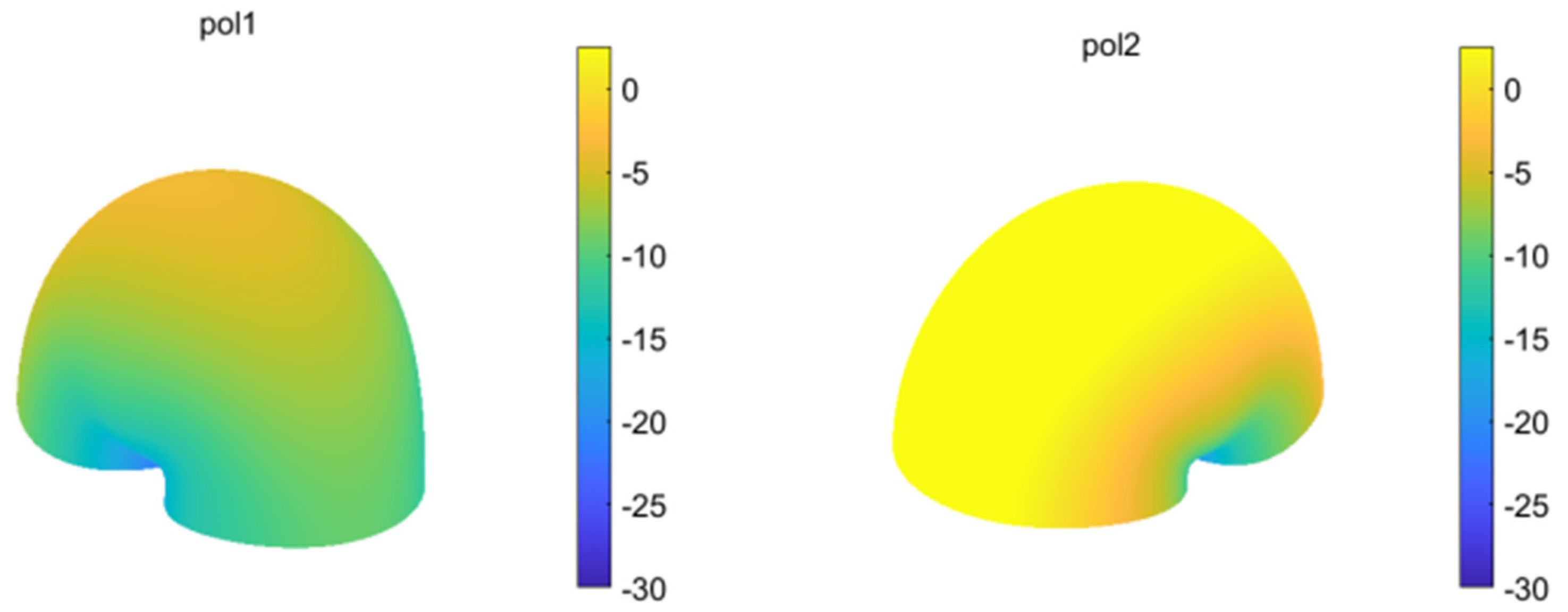
2.2.1. RIS element Pattern

The radiation pattern of the RIS element is related to factors such as:
  • the physical structure of the RIS element.
  • the single/dual polarization characteristics.
  • the frequency dependence phase/interpolation loss.
  • the incident direction and polarization direction of the incident EM wave.
Considering the above requirements for the basic model of the RIS physical model, based on the electromagnetic scattering theory and for the sake of channel modeling, we consider an infinite ideal PEC panel center unit to characterize the response of an individual element. The reflected field intensity is obtained using geometric optics, and then the scattered field of the target is solved using the physical optics far-field integration method.
The calculation of the reflected field intensity is based on geometric optics [18]. In the reflection process of an electromagnetic wave, the horizontal polarization wave and vertical polarization wave follow different laws so it is necessary to divide the incident wave into a horizontal polarization wave and a vertical polarization wave, determine the respective reflected wave, and then superimpose to obtain the total reflected field. First, two vectors need to be identified. One is the unit vector in the vertical plane of incidence:
e ^ = ( i ^ × n ^ ) / | i ^ × n ^ | .
The other is the component perpendicular to the plane of incidence and e ^
e ^ \ \ = ( i ^ × e ^ ) / | i ^ × e ^ | .
n ^ represents the surface normal vector, i ^ represents the direction of the electromagnetic wave incidence, and r ^ represents the direction of electromagnetic wave reflection.
To decompose the incident electric field E i into vertically polarized waves,
E i = ( e ^ E i ) e ^ ,
and horizontally polarized waves,
E \ \ i = ( e ^ \ \ E i ) e ^ \ \ ,
where R ¯ ¯ is the dyadic reflection coefficient, and the reflected electric field is
E r = R ¯ ¯ E i .
The reflected magnetic field is
H r = 1 Z 0 r ^ × E r .
The total field is
E = E i + E r ,
H = H i + H r .
The physical optics [19] integral formula is a generalization of the Stratton–Chu integral formula, which is obtained by modifying the Stratton–Chu formula according to the characteristics of the high-frequency region.
The Stratton–Chu integral equation [20] is as follows:
E s = s [ j ω μ ( n ^ × H ) φ + ( n ^ × E ) × φ + ( n ^ E ) φ ] d S ,
H s = s [ j ω ε ( n ^ × E ) φ + ( n ^ × H ) × φ + ( n ^ H ) φ ) ] d S .
E s and H s are the scattered fields in the far zone, respectively, whereas E and H are the electric and magnetic components of the total field, n ^ is the normal vector of the RIS element, ω are the angular frequencies, ε and μ are the free-space permittivity and permeability, and φ are the three-dimensional spatial Green’s functions.
When the far-field condition is satisfied
φ j k φ s ^ ,
where s ^ is the scattering direction unit vector.
In solving the scattered field in the high-frequency region, the Stratton–Chu integral equation can be further simplified as
E s p q = j k Z 0 1 4 π S p q s ^ × [ s ^ × ( n ^ × H ) 1 Z 0 n ^ × E ] e j k s s s s d S ,
H s p q = j k 1 4 π S p q s ^ × [ 1 Z 0 s ^ × ( n ^ × E ) + n ^ × H ] e j k s s s s d S .
where E s p q and H s p q are the scattered electric and magnetic fields excited by the RIS element S p q , E and H are the total surface electric and magnetic fields of the RIS element S p q , n ^ is the surface normal unit vector of the RIS element S p q , Z 0 is the free-space wave impedance, s are the coordinates of the surface element points in the RIS element S p q , and s are the coordinates of the far-field observation points.
For the ideal PEC, the polarization configuration of the RIS unit needs to be decomposed into two polarization directions of the RIS unit in combination, and then the synthetic radiation direction map or field point field strength of the RIS unit is calculated based on the control code book of the RIS unit in different polarization directions. If it is assumed that the unit vectors of the two orthogonal polarization directions of the RIS are V p o l 1 and V p o l 2 , then under the assumption of the ideal PEC, Equations (12) and (13) can be further simplified and decomposed as follows:
E s _ p o l 1 p q = j k Z 0 1 4 π S p q s ^ × [ s ^ × [ ( n ^ × H ) V p o l 1 ] V p o l 1 ] e j k s s s s d S ,
H s _ p o l 1 p q = j k 1 4 π S p q s ^ × [ ( n ^ × H a ) V p o l 1 ] V p o l 1 e j k s s s s d S ,
E s _ p o l 2 p q = j k Z 0 1 4 π S p q s ^ × [ s ^ × [ ( n ^ × H ) V p o l 2 ] V p o l 2 ] e j k s s s s d S ,
H s _ p o l 2 p q = j k 1 4 π S p q s ^ × [ ( n ^ × H a ) V p o l 2 ] V p o l 2 e j k s s s s d S .
In this paper, the RIS elements are discretized according to the element grid points performed. Using numerical integration, the scattered total electric field E s p q , total magnetic field H s p q , electric field E s _ p o l 1 p q , magnetic field H s _ p o l 1 p q in the first polarization direction, electric field E s _ p o l 2 p q , and magnetic field H s _ p o l 2 p q in the second polarization direction of the RIS element (p, q) excited at the target field point are obtained using Equations (12)–(17), and the two orthogonal polarization components of the RIS element can be obtained through integrated normalization by considering the energy conservation and the far-field condition of the RIS element. In the corresponding radiation polarization direction diagram, the subsequent subsections still use Equations (14)–(17) on the left-hand side of the symbol to indicate the results after normalization (see the simulation example in Section 3).

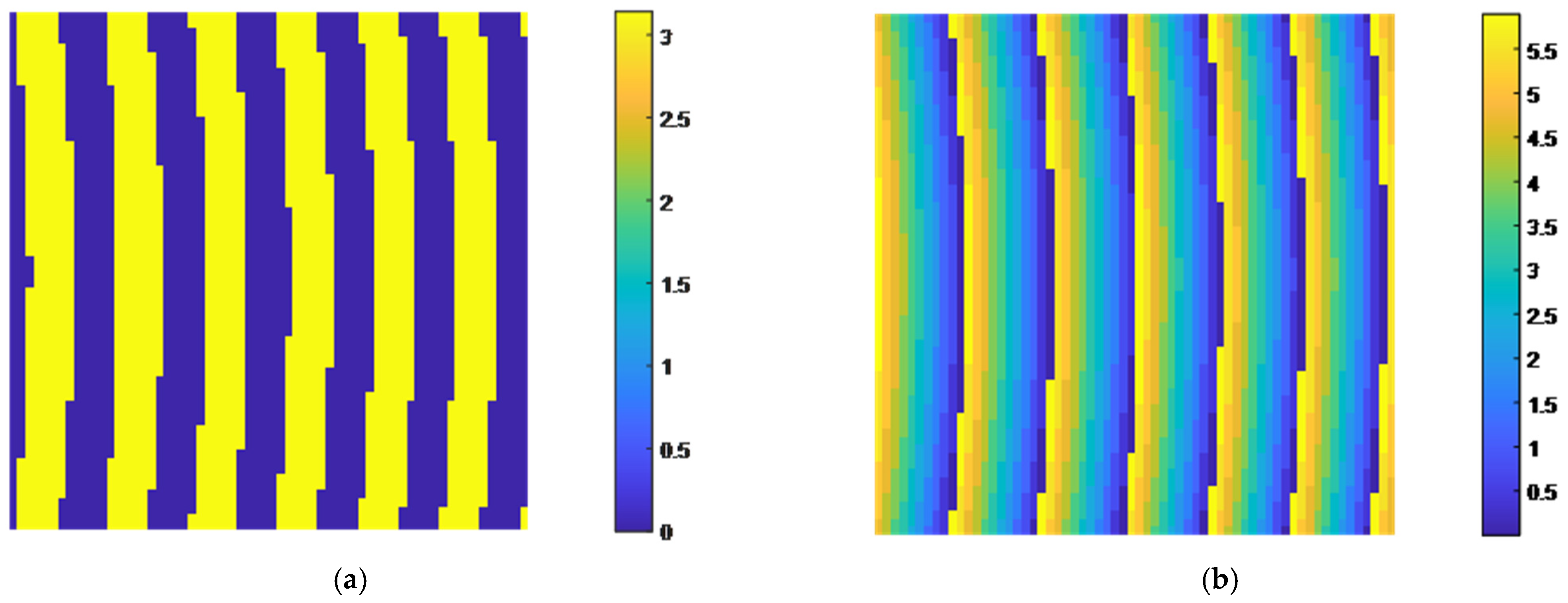
2.2.2. RIS Panel Radiation Direction Map

It is assumed that the base station and the RIS panel satisfy the far-field condition; at this time, the radiation direction map of each element of the RIS panel under the incident wave excitation is the same.
Based on the corresponding algorithm, the phase distribution of the RIS panel w p q is determined. The physical meaning is the same phase adjustment for both polarization directions of each element in the RIS panel. The phase adjustment deviation of the two polarization directions can be 0 or can be fixed or an independently controlled bias: ξ o f f , p , q . The amount of phase adjustment for each polarization direction of each element in the RIS panel is
ξ p , q p o l 1 = g ( w p , q ) ,
ξ p , q p o l 2 = ξ p , q p o l 1 + ξ o f f , p , q .
The phase of each element in the RIS panel in two polarizations φ p o l 1 p q and φ p o l 2 p q can be obtained by the superposition of the Tx-Rx travel distance phase and the code book phase.
The total effective feed-in power of the RIS panel is
P e f f i n c = η A P i n c ( λ 2 4 π ) cos ( θ i n c ) .
where η is the RIS panel-reflected power coefficient, A is the RIS panel area, P i n c is the incident wave front power, and θ i n c is the angle between the incident wave vector and the RIS panel normal.
Under the far-field assumption, the average effective feed-in power of each RIS unit is
P r i s = P e f f i n c N r i s .
where N r i s is the number of RIS elements.
In the first polarization direction,
E s _ p o l 1 = p , q E s _ p o l 1 p q P r i s λ 2 ( 4 π L p q ) 2 e j φ p o l 1 p q ,
H s _ p o l 1 = p , q H s _ p o l 1 p q P r i s λ 2 ( 4 π L p q ) 2 e j φ p o l 1 p q .
In the second polarization direction,
E s _ p o l 2 = p , q E s _ p o l 2 p q P r i s λ 2 ( 4 π L p q ) 2 e j φ p o l 2 p q ,
H s _ p o l 2 = p , q H s _ p o l 2 p q P r i s λ 2 ( 4 π L p q ) 2 e j φ p o l 2 p q .
where L p q is the distance from the center of each RIS element to the scattered field point.
Then, the total scattered field at the target field point is
E s _ p o l = E s _ p o l 1 + E s _ p o l 2 ,
H s _ p o l = H s _ p o l 1 + H s _ p o l 2 .

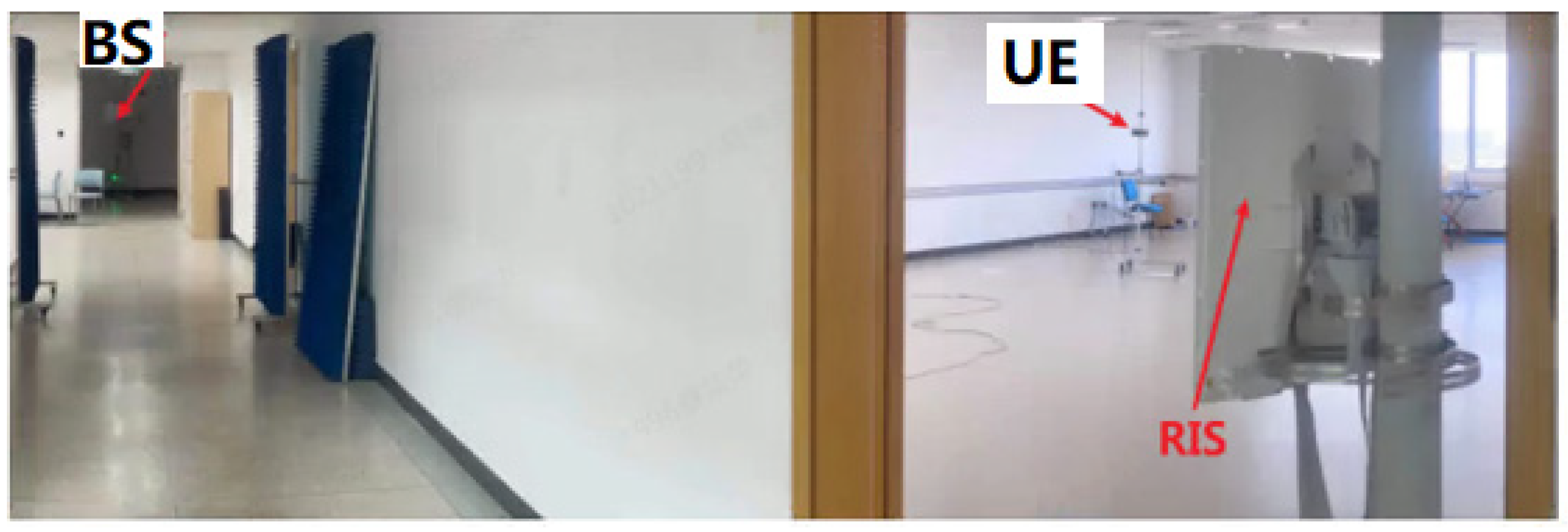
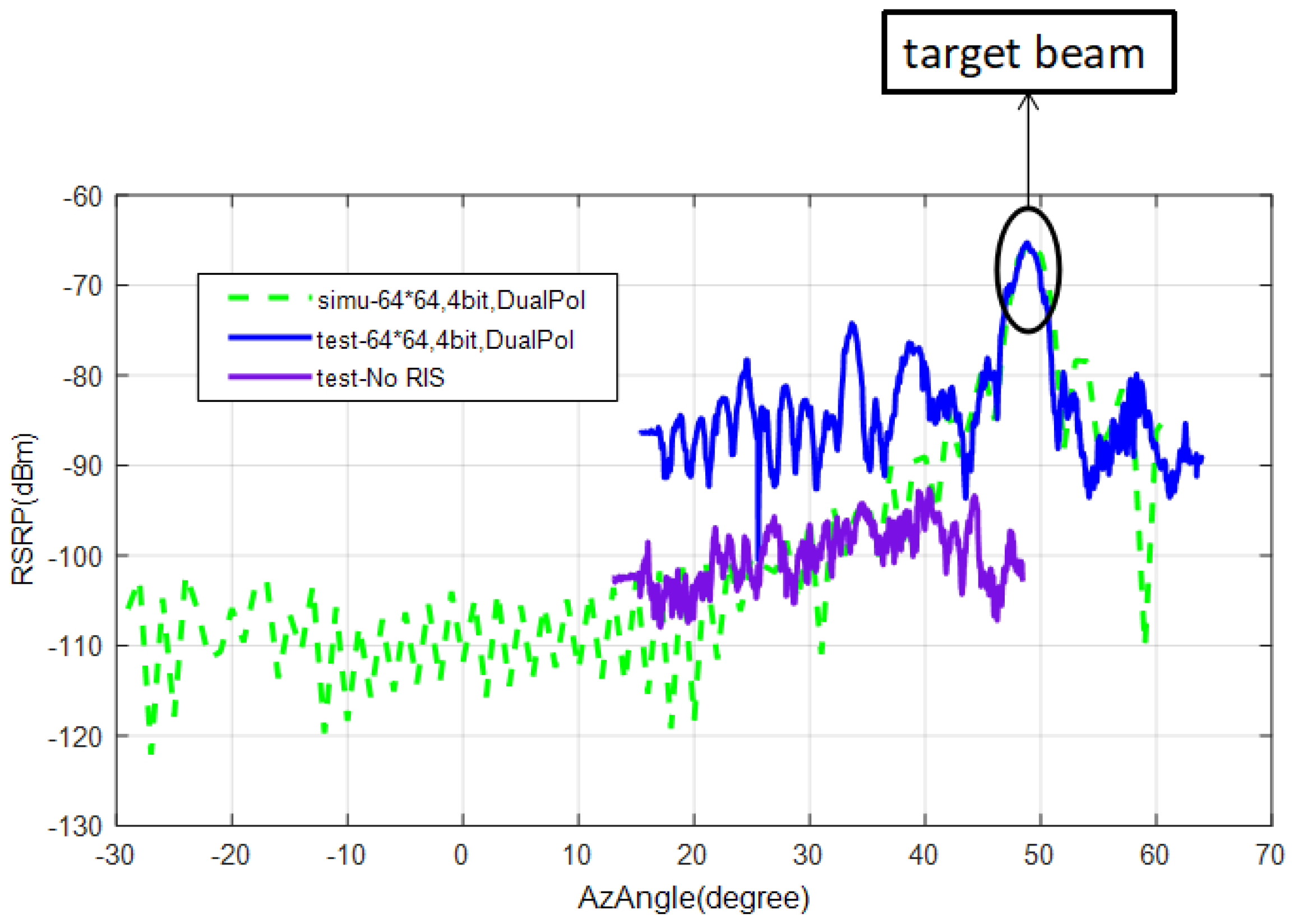
3. Simulation Verification
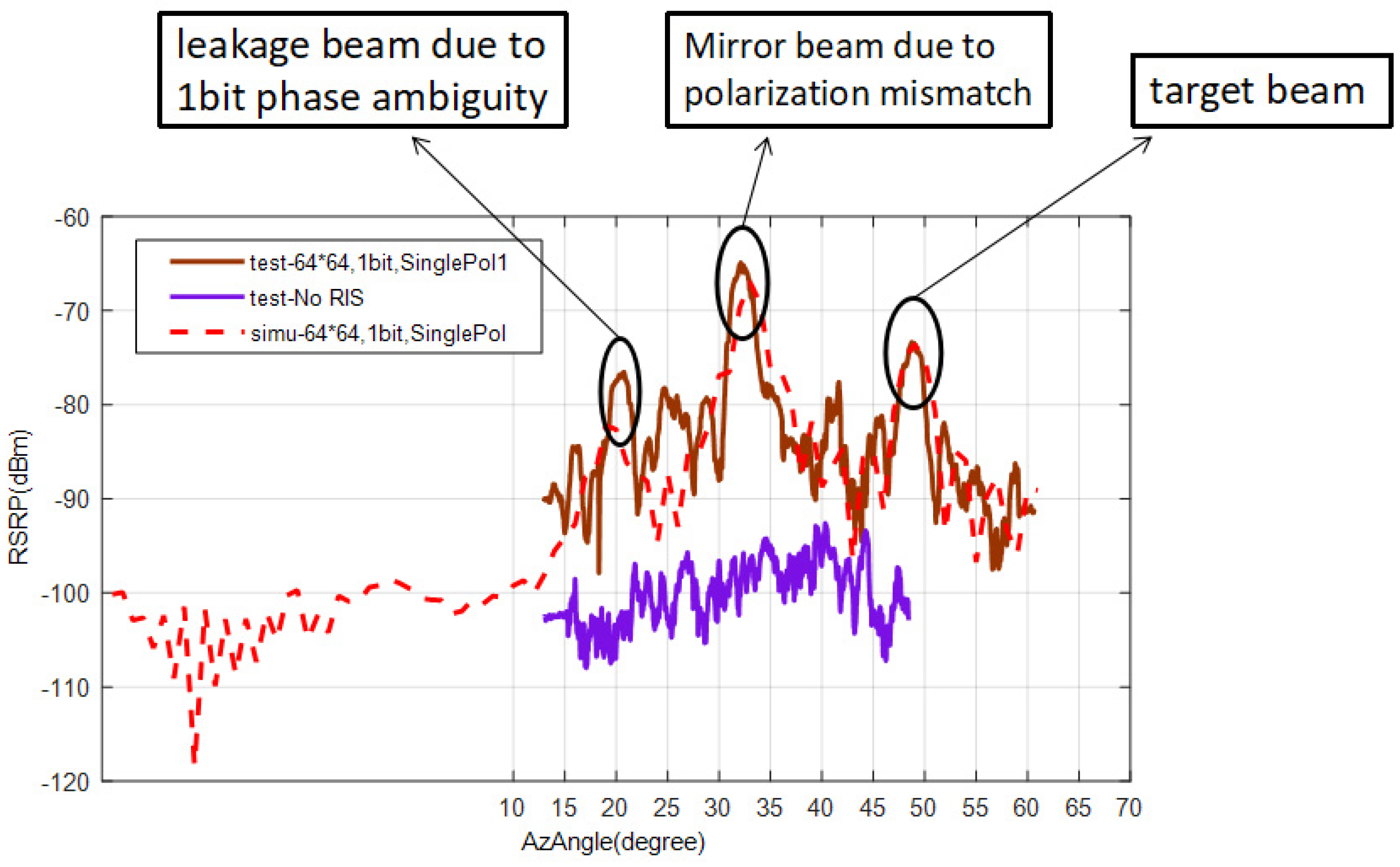
The RIS physical model abstract simulation parameters are shown in Table 1.
The simulation results are shown below. The radiation direction diagram of the RIS unit is shown in Figure 1 and the phase distribution of the RIS panel is shown in Figure 2.
The indoor RIS test was conducted in Shanghai ZTE Park. Figure 3 shows the RIS panel indoor deployment. The BS and RIS were deployed in the corridor and the terminals were deployed indoors. A comparison of the measured and simulated results of the RIS deployment indoors is shown in Figure 4 and Figure 5. Figure 4 shows a comparison of the measured and simulated results of the 1-bit single-polarized panel and Figure 5 shows a comparison of the measured and simulated results of the 4-bit dual-polarized panel.
From the simulation parameters, the incident angle was 32 degrees and the reflection angle was 48 degrees. Although some of the derived beams were filtered by deploying absorbers in the environment, there were still some reflected waves reflected in the measured results. In Figure 4, it can be seen that the 1-bit phase ambiguity led to beam leakage and the polarization mismatch led to a mirror beam. Overall, the simulation had no reflected waves generated by the environment, and the received power of the reference signal at the target angle was very close to the measured results (the 1-bit single-polarized panel and the 4-bit dual-polarized panel), verifying the availability and accuracy of the RIS physical model abstraction and channel model described in this paper.

4. Results

In this paper, a reflective RIS physical model is proposed to facilitate channel modeling in system simulation. The model can calculate the directivity coefficient of the RIS panel simply and quickly and can be applied to the calculation of the channel coefficient. Based on the impinging EM wave of the last bounce to the RIS, the scattering field intensity of the target point is obtained using geometric optics and the electric field surface integration method of physical optics. According to the designed algorithm, simulation tests are carried out to realize the abstraction of the physical model of the RIS for application in channel modeling in a practical scenario. In the follow-up work, the extended model for the RIS physical model construction was built to further improve the built physical model.

Author Contributions

Conceptualization, Y.C. (Yijian Chen) and J.Y.; methodology, J.D.; software, Y.C. (Yijun Cui); validation, Y.L., J.D. and Y.C. (Yijun Cui); formal analysis, F.Q.; investigation, Y.W.; resources, Y.C. (Yijun Cui); data curation, J.D.; writing—original draft preparation, Y.L.; writing—review and editing, Y.L.; visualization, J.D.; supervision, J.D.; project administration, Y.W.; funding acquisition, J.D. All authors have read and agreed to the published version of the manuscript.

Funding

This research received no external funding.

Conflicts of Interest

The authors declare no conflict of interest.

Nomenclature

For the purposes of the present paper, the following symbols apply:
e ^ the unit vector in the vertical plane of incidence
e ^ / / the component perpendicular to the plane of incidence and e ^
i ^ the direction of electromagnetic wave incidence
n ^ the normal vector of the RIS panel
r ^ the direction of electromagnetic wave reflection
E i the incident electric field
E / / i the electric field of horizontally polarized waves
E i the electric field of vertically polarized waves
R = the dyadic reflection coefficient
E r the reflected electric field
H i the incident magnetic field
H r the reflected magnetic field
E the total electric field
H the total magnetic field
E s the scattered electric fields in the far zone
H s the scattered magnetic fields in the far zone
ω the angular frequencies
ε the free-space permittivity
μ the free-space permeability
φ the three-dimensional spatial Green’s functions
s ^ the scattering direction unit vector
E s p q the scattered electric fields excited by the RIS element S p q
H s p q the scattered magnetic fields excited by the RIS element S p q
Z 0 the free-space wave impedance
s the coordinates of the surface element points in the RIS element S p q
s the coordinates of the far-field observation points
E s _ p o l 1 p q the electric field excited by the RIS element S p q in the first polarization direction
H s _ p o l 1 p q the magnetic field excited by the RIS element S p q in the first polarization direction
E s _ p o l 2 p q the electric field excited by the RIS element S p q in the second polarization direction
H s _ p o l 2 p q the magnetic field excited by the RIS element S p q in the second polarization direction
ξ o f f , p , q the controlled bias
P e f f i n c the total effective feed-in power of the RIS panel
η the RIS panel-reflected power coefficient
A the RIS panel area
P i n c the incident wave front power
θ i n c the angle between the incident wave vector and the RIS panel normal
P r i s the average effective feed-in power of each RIS unit
N r i s the number of RIS elements
E s _ p o l 1 the electric field in the first polarization direction
H s _ p o l 1 the magnetic field in the first polarization direction
E s _ p o l 2 the electric field in the second polarization direction
H s _ p o l 2 the magnetic field in the second polarization direction
E s _ p o l the total scattered electric field at the target field point
H s _ p o l the total scattered magnetic electric field at the target field point

References

  1. Dou, J.W.; Chen, Y.J.; Zhang, N.; Fang, M.; Peng, L. On the channel modeling of intelligent controllable electromagnetic-surface. Chin. J. Radio Sci. 2021, 36, 368–377. (In Chinese) [Google Scholar]
  2. Degli-Esposti, V.; Vitucci, E.M.; Di Renzo, M.; Tretyakov, S. Reradiation and scattering from a reconfigurable intelligent surface: A general macroscopic model. IEEE Trans. Antennas Propag. 2022, 1. [Google Scholar] [CrossRef]
  3. Di Renzo, M.; Danufane, F.H.; Tretyakov, S. Communication models for reconfigurable intelligent surfaces: From surface electromagnetics to wireless networks optimization. arXiv 2021, arXiv:2110.00833. [Google Scholar]
  4. Danufane, F.H.; Di Renzo, M.; De Rosny, J.; Tretyakov, S. On the path-loss of reconfigurable intelligent surfaces: An approach based on Green’s theorem applied to vector fields. IEEE Trans. Commun. 2021, 69, 5573–5592. [Google Scholar] [CrossRef]
  5. Di Renzo, M.; Danufane, F.H.; Xi, X.; De Rosny, J.; Tretyakov, S. Analytical modeling of the path-loss for reconfigurable intelligent surfaces–anomalous mirror or scatterer? In Proceedings of the 2020 IEEE 21st International Workshop on Signal Processing Advances in Wireless Communications (SPAWC), Atlanta, GA, USA, 26–29 May 2020; pp. 1–5. [Google Scholar]
  6. Balanis, C.A. Antenna Theory: Analysis and Design; John Wiley & Sons: Hoboken, NJ, USA, 2015. [Google Scholar]
  7. Ellingson, S.W. Path loss in reconfigurable intelligent surface-enabled channels. In Proceedings of the 2021 IEEE 32nd Annual International Symposium on Personal, Indoor and Mobile Radio Communications (PIMRC), Helsinki, Finland, 13–16 September 2021; pp. 829–835. [Google Scholar]
  8. Özdogan, Ö.; Björnson, E.; Larsson, E.G. Intelligent reflecting surfaces: Physics, propagation, and pathloss modeling. IEEE Wirel. Commun. Lett. 2019, 9, 581–585. [Google Scholar] [CrossRef]
  9. Díaz-Rubio, A.; Tretyakov, S.A. Macroscopic modeling of anomalously reflecting metasurfaces: Angular response and far-field scattering. IEEE Trans. Antennas Propag. 2021, 69, 6560–6571. [Google Scholar] [CrossRef]
  10. Tang, W.; Chen, M.Z.; Chen, X.; Dai, J.Y.; Han, Y.; Di Renzo, M.; Zeng, Y.; Jin, S.; Cheng, Q.; Cui, T.J. Wireless communications with reconfigurable intelligent surface: Path loss modeling and experimental measurement. IEEE Trans. Wirel. Commun. 2020, 20, 421–439. [Google Scholar] [CrossRef]
  11. Tang, W.; Chen, X.; Chen, M.Z.; Dai, J.Y.; Han, Y.; Di Renzo, M.; Jin, S.; Cheng, Q.; Cui, T.J. Path loss modeling and measurements for reconfigurable intelligent surfaces in the millimeter-wave frequency band. arXiv 2021, arXiv:2101.08607. [Google Scholar]
  12. Najafi, M.; Jamali, V.; Schober, R.; Poor, H.V. Physics-based modeling and scalable optimization of large intelligent reflecting surfaces. IEEE Trans. Commun. 2020, 69, 2673–2691. [Google Scholar] [CrossRef]
  13. Suter, E.; Mosig, J.R. A subdomain multilevel approach for the efficient MoM analysis of large planar antennas. Microw. Opt. Technol. Lett. 2000, 26, 270–277. [Google Scholar] [CrossRef]
  14. Ling, F.; Jin, J.M. Hybridization of Sbr and Mom for Scattering By Large Bodies With Inhomogeneous Protrusions—Summary. J. Electromagn. Waves Appl. 1997, 11, 1249–1255. [Google Scholar] [CrossRef]
  15. Ling, H.; Chou, R.C.; Lee, S.W. Shooting and bouncing rays: Calculating the RCS of an arbitrarily shaped cavity. IEEE Trans. Antennas Propag. 1989, 37, 194–205. [Google Scholar] [CrossRef]
  16. Jin, J.M.; Ni, S.S.; Lee, S.W. Hybridization of SBR and FEM for scattering by large bodies with cracks and cavities. IEEE Trans. Antennas Propag. 1995, 43, 1130–1139. [Google Scholar]
  17. Bhalla, R.; Ling, H. A fast algorithm for signature prediction and image formation using the shooting and bouncing ray technique. IEEE Trans. Antennas Propag. 1995, 43, 727–731. [Google Scholar] [CrossRef]
  18. Katz, M. Introduction to Geometrical Optics; World Scientific: Singapore, 2002. [Google Scholar]
  19. Wood, R.W. Physical Optics; Macmillan: New York, NY, USA, 1905. [Google Scholar]
  20. Stratton, J.A.; Chu, L.J. Diffraction theory of electromagnetic waves. Phys. Rev. 1939, 56, 99. [Google Scholar] [CrossRef]
Figure 1. Radiation direction diagram of the RIS unit.
Electronics 11 02798 g001
Figure 2. RIS panel phase distribution. (a) RIS panel phase distribution for a 1-bit single-polarized panel; (b) RIS panel phase distribution for a 4-bit dual-polarized panel.
Electronics 11 02798 g002
Figure 3. RIS panel indoor deployment.
Electronics 11 02798 g003
Figure 4. Comparison of the measured and simulated results of the 1-bit single-polarized panel.
Electronics 11 02798 g004
Figure 5. Comparison of the measured and simulated results of the 4-bit dual-polarized panel.
Electronics 11 02798 g005
Table 1. RIS physical model abstraction simulation parameters.
ParametersValueUnit
Base station location[19.99, 0.69, 1]Tm
RIS location[0, 0, 1]Tm
Receiving point location[2.08, −9.78, 1]Tm
RIS azimuth angle −30degree
RIS elevation angle0degree
RIS slant angle0degree
Polarization of 1-bit RIS panelSingle polarization with −45-degree rotation with respect to horizontal edge of RIS paneldegree
Polarization of 4-bit RIS panelDual polarization with ±45-degree rotation with respect to horizontal edge of RIS paneldegree
Incident wave vector polarization angle−23degree
RIS orthogonal polarization phase bias0degree
Carrier frequency26.9GHz
Number of RIS elements
(Nx × Ny)
64 × 64-
RIS horizontal array spacing0.45 λ
RIS vertical array spacing0.45 λ
Publisher’s Note: MDPI stays neutral with regard to jurisdictional claims in published maps and institutional affiliations.

