Article

IR-UWB Radar-Based Robust Heart Rate Detection Using a Deep Learning Technique Intended for Vehicular Applications

1
CNRS, Lab-STICC, Univ Brest, CS 93837, 6 Avenue Le Gorgeu, CEDEX 3, 29238 Brest, France
2
ENIB, CNRS, Lab-STICC, 29200 Brest, France
*
Author to whom correspondence should be addressed.
Electronics 2022, 11(16), 2505; https://doi.org/10.3390/electronics11162505
Submission received: 9 July 2022 / Revised: 5 August 2022 / Accepted: 8 August 2022 / Published: 11 August 2022
(This article belongs to the Special Issue New Trends and Methods in Communication Systems)

Abstract

:
This paper deals with robust heart rate detection intended for the in-car monitoring of people. There are two main problems associated with radar-based heart rate detection. Firstly, the signal associated with the human heart is difficult to separate from breathing harmonics in the frequency domain. Secondly, the vital signal is affected by any interference signal from hand gestures, lips motion during speech or any other random body motions (RBM). To handle the problem of the breathing harmonics, we propose a novel algorithm based on time series data instead of the conventionally used frequency domain technique. In our proposed method, a deep learning classifier is used to detect the pattern of the heart rate signal. To deal with the interference mitigation from the random body motions, we identify an optimum location for the radar sensor inside the car. In this paper, a commercially available Novelda Xethru X4 radar is used for signal acquisition and vital sign measurement of 5 people. The performance of the proposed algorithm is compared with and found to be superior to that of the conventional frequency domain technique.

1. Introduction

Continuous, real-time monitoring of physiological parameters, such as breathing rate (BR) and heart rate (HR), may be necessary to assess the well-being of an elderly person or the drowsiness of a perceptive car driver. Recently, radar-based non-invasive vital sign detection has become a hot research topic [1]. Early systems for vital sign detection were based on continuous-wave (CW) radar due to their simple architecture and low cost [2]. However, such radar is not able to measure the distance to the subject due to its very poor range ambiguity, and noise cannot be filtered out based on the proximity of the sources to the subject [3]. These issues may be solved by using stepped frequency-modulated continuous wave (SFCW) [4] and frequency-modulated continuous wave (FMCW) radar [5,6,7,8]. Although SFCW and FMCW radars can both detect vital signs and measure the range to the target, such solutions are more power consuming and costly compared to CW radar. Another attractive solution for non-invasive vital sign detection is the impulse radio ultra-wideband (IR-UWB) technology [9,10], due to its unique capabilities, such as high resolution, good penetration, low power requirement and simple hardware design. IR-UWB radar has been used in various applications such as multi-human localization [11], human computer interaction [12], gesture recognition [13,14,15] and vital sign monitoring [16,17,18,19,20,21]. Recently, many research works are focused on improving the accuracy of vital sign detection by either employing novel signal processing algorithms and/or by using specific experimental design setup for signal acquisition. A novel algorithm based on singular value decomposition (SVD) was proposed for signal denoising and wavelet transform was successfully used for vital sign extraction [18]. I. Choi et al. [22] have proposed an algorithm for robust heart rate estimation using IR-UWB radar. Three candidate peaks for heart rate are selected and the most suitable of them is selected as heart rate by using fuzzy logic. In a recently published work, a UWB radar on a drone was used to detect the respiration rate of human through the wall [23]. The proposed methods successfully suppressed the vibrations generated due to unbalanced motor motion and the respiration signal was also enhanced. In a recent study, an algorithm was designed based on data fusion from two radar sensors and correlation technique to measure vital signs accurately compared to a one radar-based vital sign measurement [24]. A novel adaptive spectrum estimation algorithm was proposed in [25] to detect the heart rate accurately in the presence of breathing harmonics as well as inter-modulation of breathing and heart rate signals through UWB radar sensor. In another work [26], researchers used a fusion of radar and computer vision with RealSense RGB and depth sensor to improve the accuracy of vital sign measurement.
Although radar-based vital sign detection is a convenient approach, there are challenges associated with it. The main challenge associated with the signal processing is the separation of breathing and heart rate. Traditionally, frequency domain techniques such as Fourier transform (FT) are used for extracting the breathing and heart frequencies from the spectrum of the vital signal. For this purpose, band pass filters are used, as breathing and HR have their own frequency bands. However, the breathing harmonics and intermodulation of breathing and heart rate signals may also occur in the frequency range of HR. This makes it difficult to distinguish the harmonics and HR. To this end, we propose an algorithm based on time series data, which is the original vital signal instead of converting it into frequency domain. The proposed algorithm consists of three main stages, i.e., heart pattern extraction, pattern classification and heart rate detection.
Another challenge associated with radar-based vital sign detection is the effect of motion artifacts on the measurement process. There have been studies carried out on the effect of motion artifacts on vital signs and thus to compensate it. For instance, in [23] the random body motion detection during vital sign measurement was studied and the interval of signal affected by RBM was separated from the whole signal duration. However, the vital signal was not detected during this interval and it was just considered a noisy signal. Changzhi Li et al. [24] have worked on reducing the motion artifacts during vital sign measurement in different scenarios such as sleep monitoring and lie detection. In that study, complex signal demodulation and arctangent demodulation techniques were used for RBM cancellation. Qinyi et al. [25] have employed matched filters to detect the vital signs in the presence of large-scale RBM. Mengyao Yang et al. [27] have worked on radar-based vital signs of multiple people in a car. In that work, the variational mode decomposition (VMD) method has been employed to find the vital signs of the driver and the passengers with a single radar. Our work is focused on vital sign detection inside a perceptive car, which is able to interact with its driver and passengers based on their vital signs and behavioral patterns. Therefore, it is important to devise a strategy to compensate the effect of RBM due to the motion of the car. Thus, we have determined an optimal location for radar sensor, so that the radar signal is least affected by the interference from RBM and other external interfering movements inside the car.
In this work, IR-UWB commercial radar sensors were deployed for signal acquisition. All the experiments were performed in real time using actual radar sensors. The backscattered signal is pre-processed for clutter and noise cancellation. An optimum point on the human body is selected based on the maximum variation in the backscattered signal. The vital signal is then collected for a certain time period. A deep learning classifier is used to select the segments of the vital signal which matches the training data of heart signal patterns. The intervals among the peaks of the vital signal are analyzed using a statistical method to detect the heart rate of the human subject. Multiple human targets were used for the experiments to show the performance of the proposed algorithm.
The original contributions of the paper are that we have proposed an algorithm based on time series data instead of the frequency domain data. A deep learning algorithm based on AlexNet and SVM was employed for the classification of the original HR signal from the motion artifacts due to the body motion or motion of the vehicle. Another contribution of this work is that the algorithms are developed and tested on real data obtained from the commercial radar sensors instead of only using simulation-based algorithms.
Apart from the above contributions, there are certain limitations associated with our research: (a) The experiments were performed in the car while it was not moving on the road, so the effect of the movements due to driving is not taken into account. (b) We put the sensor on the front side of the seat facing the back of the human. Since the main goal is to deploy the sensor inside the seat or at the backside of the seat, the effect of the seat attenuation should also be included for more accurate results. We plan to address these issues in future work.
The rest of paper is organized as follows. Section 2 describes the pre-processing of the raw data acquired with the radar sensor. The problems associated with in-car vital sign monitoring are also discussed. In Section 3, the proposed algorithm is presented and discussed in detail. Experimental results and obtained performance are discussed in Section 4, followed by the conclusion and future work.

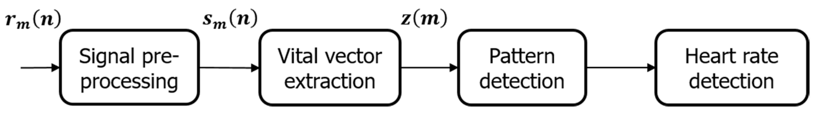
2. Signal Pre-Processing and Problem Statement

In order to have an overview of the vital detection system presented in this work, a block diagram of the system is shown in Figure 1.
First, we perform the vital signal extraction from the backscattered raw data. The raw signal r m ( n ) is passed through a decluttering filter to remove the unnecessary reflections from the background. The resulting decluttered signal is represented by s m ( n ) . Then, the column of maximum variance is extracted as a vital signal represented by z ( m ) . The variables ‘ m ’ and ‘ n ’ stand for time and range and will be explained in detail in Equation (1). Since the vital signal is non-stationary over time, some segments of the signal might be corrupted by noise or huge body movements. In order to remove the corrupted segments of the signal, a pattern detection algorithm is implemented in this work. A one-class classifier allows us to find the segments of the signal which have a similar pattern to the stored patterns of the vital signal and discarding the remaining segments that are not similar to a pre-defined dataset of vital signals. Using this filtered vital signal, the heart rate is detected using the time period of the signal segments.
Let us consider the raw data acquired by the IR-UWB radar, which contains the signal from the human body, as well the signal from the static background objects such as floor, walls and chair. Since we are interested in the signal that is reflected from the human body, we need to filter out all the unnecessary clutter components from the background environment. This is accomplished by clutter removal filter as explained below.
The backscattered signal is represented as:
r m ( n ) = l = 1 L a m l p ( n τ m l ) + ( n )  
where n and m stand for the fast time and slow time index, respectively. The fast time is directly related to the range or distance of the object from the radar and slow time represents the acquisition time. The acquisition time corresponds to the real time during which the experiment is performed and it has the unit of seconds. The slow time index is converted to the real time by using the receiver sampling frequency and the velocity of light. Fast time is associated with the time of arrival (ToA) of the transmitted impulse. The variables τ m l and a m l are the time delay and the amplitude associated with the lth multipath. p ( n ) and ( n ) represent the elementary radar waveform and additive noise, respectively. In order to remove the clutter components from the backscattered signal, a loopback filter is used [28], which may be represented as follows:
c m ,   n = α c m 1 ,   n + ( 1 α ) r m ,   n
  s m ,   n = r m , n c m , n
where α is proportional to the signal to clutter ratio, c m ,   n represents the clutter signal and s m ,   n is the filtered signal after removal of the clutter components. During initialization, the raw signal is considered as the clutter signal (for m = 1). Next, the clutter signal is updated according to Equation (2) (when m > 1). A lower value of α results in a faster estimation of the environment clutter, but the clutter signal may be affected by impulse noise. Comparatively, a higher value of α needs longer time for clutter estimation, but it makes it more robust to impulse noise [29]. An experiment was performed and the data with clutter and the resulting decluttered signal are shown in Figure 2.
In Figure 2a, the backscattered raw signal is shown, which shows clutter components at distance near the radar. Figure 2b shows the signal after the removal of clutter using Equations (2) and (3). It can be noticed from Figure 2b that the target at distance of 30–45 cm is clearly observable after the removal of the clutter signal. The value of parameter α was 0.9 for the experiments in this work.
After removing the clutter components, the range where maximum chest displacement occurs is determined. In the literature, the most prevalent method is to choose the row with the maximum variance as the suitable range for extracting the vital signal z[n].
The resulting vital signal at the output of the maximum variance technique is shown in Figure 3a. Conventionally, the time domain signal is transformed to the frequency domain and then BR is detected from the spectrum range of 10–30 bpm and HR is detected as the peak signal in the spectrum range of 50–120 bpm. To extract BR and HR from the spectrum, bandpass filters are used. This approach may be very effective in cases when BR and HR follow sinusoidal patterns. However, the BR may not be exactly a sinusoidal pattern and therefore its spectrum contains harmonics at multiples of the BR frequency. There may also be intermodulation components due to the BR and HR signals [9]. The breathing frequency harmonics may occur in the frequency range of HR and therefore it is difficult to distinguish the BR harmonics from HR.
The vital signal in the frequency domain is shown in Figure 3b. The actual breathing and heart rate are 10 bpm and 103 bpm, respectively. For the above example, the actual breathing rate was obtained by manual count while the HR was obtained by ECG sensor. Due to the intermodulation of breathing and heart frequencies, there are several frequency peaks that occur in the range of heart rate frequencies. The highest frequency peak in the frequency range of HR is at 69 bpm which is not actually a heart rate value but a false alarm created by the intermodulation of BR and HR. This value is close to the intermodulation of the HR (103 bpm) and the third breathing harmonics (30 bpm). The little shift may be caused by noise or due to the approximation of the BR. Currently, researchers have dealt with this problem in the frequency domain such as in [9], where the authors have proposed a solution based on notch filters, which may suppress the breathing harmonics. This solution performs well when the breathing harmonics and HR are separated clearly. However, when the breathing harmonics are located close to the HR, then the notch filter may also suppress the true HR frequency and thus result in a false alarm. In order to deal with this problem, an algorithm is proposed in Section 4.
Another problem specific to the in-car vital sign monitoring is the RBM during driving. Leem et al. [30] have demonstrated the feasibility of estimating the vital signs of the driver using IR-UWB radar inside a vehicle. They have also shown that this method can be useful to detect the drowsiness of the driver which may be very helpful to reduce the risk of accidents. However, the problem related to BR harmonics was not mentioned in that work and the position of the radar sensor was not optimized to reduce the interference from the random body motion of the driver or any other driving-related motions. Zhicheng Yang et al. [31] have also studied radar-based in-vehicle vital sign monitoring. An optimum position inside the vehicle was determined using a total of 16 different positions inside a car. By comparing the results from all the positions, the rear-view mirror was found to be the confident position. This work was mainly aimed at breathing monitoring. Since breathing motion is larger than heart rate motion, the rear mirror may be optimal position for breathing monitoring, but as heart motion is very minor, the incident angle also affects the magnitude of the reflected signal. In our work, the main focus is on heart rate measurement, so we choose a position where the heart motion has sufficient magnitude, while the breathing magnitude is small, so that it may not interfere with the heart motion. Another important factor that we need to consider in selecting the optimal point for in-car HR monitoring is that the interference from outside motions, such as a motion by the body of nearby sitting passenger or the hand gesture of the driver itself, is minimum so that the HR may be detected robustly.

3. Proposed Algorithm

The following Figure 4. shows an overview of the signal processing steps involved in extracting the accurate value of HR from the vital signal which may be contaminated with external noise.
The proposed algorithm consists of the following steps. In the first step, the part of the signal which refers to the heart rate cycle is extracted. In Figure 4, it is represented by z ( m ) . Then, the signal is divided into smaller segments. The segmented signal is represented by z ( m ) . In the second step, the segments are transformed into grayscale images I ( m ) using image processing steps such as image resizing and image pixel normalization. Then, the resulting images are classified whether it matches the images stored in the training database obtained from the sample heart rate signal or not. This step is performed by employing a one-class classifier. The proposed one-class classifier is a combination of CNN and an SVM. This step removes the unwanted segments that do not resemble the heart rate pattern. In the next step, an algorithm is used based on local peaks to detect the heart rate. Each step is detailed below.

3.1. Signal Segmentation and Image Transformation

Vital signal comprises many cycles of heart rate signals, depending on the length of the signal. The time interval between two consecutive peaks represents the instantaneous time period of the heart rate. In order to calculate this time interval, it is important to obtain the local peaks which refer to the heart motion. A peak detection algorithm is used in this paper to find local peaks from the vital signal, as illustrated in Figure 5.
The peak detection algorithm cannot discriminate whether a peak is due to the heart motion or some random noise. In order to distinguish the peaks that are caused by heart motion from the peaks due to noise or other interferences, it is necessary to analyze the pattern of the signal between the peaks. The vital signal is first divided into smaller segments. Each segment consists of four consecutive peaks. The pattern corresponding to the heart rate duration is transformed into an image as illustrated in Figure 6. All the x and y axis data are removed from plots before conversion into images because we are only interested in the shape of the segments for classification. The images are then resized into a same size (50 × 50) because of the different lengths of the segments.
In order to create a dataset of the signal segments, so that the deep learning algorithm can use it for training the weights of the neural network, we have divided the vital signal into segments consisting of four consecutive peaks. The two peak-based segments are not appropriate because of the very short duration and sometimes they do not result in good patterns. Therefore, we have chosen four peak-based patterns in this work. In the future, lengthier signal segments may be chosen for performance comparison.

3.2. Pattern Classification

The above peak detection method only finds peaks, but it is not sure that these peaks originate from heart pattern or some noise signal. In order to make a decision, we use one-class classifier algorithm. Since this is a pattern recognition tasks, the local signal portion between four consecutive peaks is converted into an image, as previously mentioned. Then, the features are extracted using AlexNet, a pre-trained CNN successfully used in many fields such as computer vision [32], natural language processing [33] and radar signal processing [34,35]. After feature extraction, the one-class classification is performed through SVM. AlexNet architecture is given in Figure 7, while the global classification block diagram is provided in Figure 8.
AlexNet is trained with millions of images and has eight deep layers: five convolution layers and three fully connected layers. The convolution layers are mainly used for automatic feature extraction from the input image. Max pooling method is used in this architecture to reduce the size of the image after each convolution layer. The final fully connected layer in AlexNet contains a softmax activation function, which yields a vector representing a probability distribution over one thousand classes. We have employed AlexNet for feature extraction only. A set of 4096 features are extracted from the input image. The classification tasks are performed by an SVM, whose output is only one class. It is similar to the task of anomaly detection, where the desired class is known and the outlier features are not known to the classifier. The block diagram of the CNN-SVM classifier to detect the anomaly pattern is shown in Figure 8.
SVM is a machine learning technique and it may be used in both supervised learning as well as unsupervised learning. In one-class classification technique, it may be used as an unsupervised learning method. It projects the input data in a higher dimension space using a non-linear transformation and learns to linearly separate the classes in the projected space by a hyperplane. There are certain hyperparameters, commonly used in the literature [36,37], that need to be chosen for the selected SVM model. Since we are working with one-class SVM, we have chosen the following parameters as follows: We have used radial basis function (RBF) to train the SVM model, with the kernel scale properly selected by the Harris Hawk optimization algorithm (HHO), and sequential minimal optimization (SMO) as the optimization approach for the SVM implemented in this work.

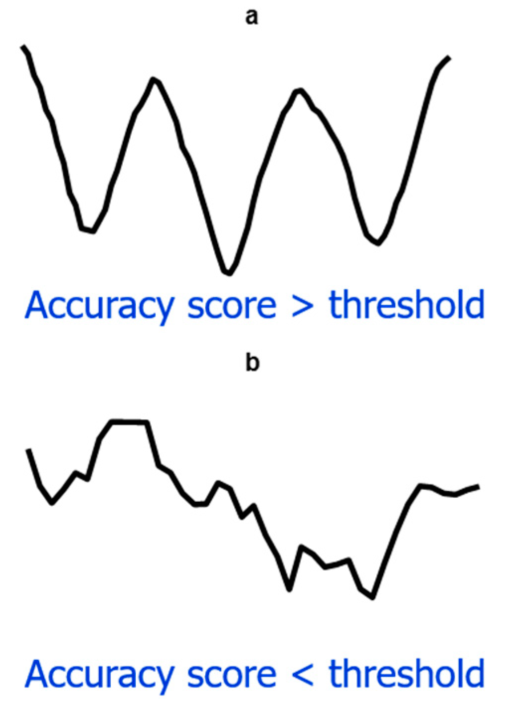
3.3. Heart Rate Detection

After the classification of the image segments as heart rate pattern and noise pattern, the heart rate is determined from the set of intervals between the resulting peaks. Since the resulting data consist of two HR cycles, we have to divide the duration of these segments by a factor of 2 to obtain the accurate value of the HR. An illustration of the segment duration and time domain-based HR extraction is provided in Figure 9.
In Figure 9, the peak interval represents the number of samples between two consecutive peaks. This interval is later translated to frequency by applying the receiver sampling rate. In Figure 9a, the histogram represents the segment duration when no classification algorithm is applied. Therefore, it contains some small duration segments which refer to false alarm segments of the HR. These false alarm segments might be caused by some interference noise or random body motion, HR and BR harmonics or the intermodulation of these signals. In Figure 9b, these false alarm segments are successfully removed by the trained AlexNet and SVM-based one-class classifier which differentiates the HR-related patterns and the false alarm patterns. In this paper, we have taken the mean value of the durations as the parameter to estimate the HR. From this mean value and slow time sampling frequency, the HR may easily be extracted by the following formula.
HR   = Samples   per   sec ond Samples   per   cycle  
The slow-time sampling frequency for the experiment was 30 samples/second. The mean interval values, i.e., samples per cycle, for Figure 9a,b were 21.42 and 23.37 samples, respectively. Equation (4) results in a HR of 84 bpm for Figure 9a and 77 bpm for Figure 9b, whereas the actual HR was obtained as 78.5 bpm. It is thus demonstrated that the proposed algorithm improves the accuracy of the HR measurement compared to the conventional approach.

4. Results

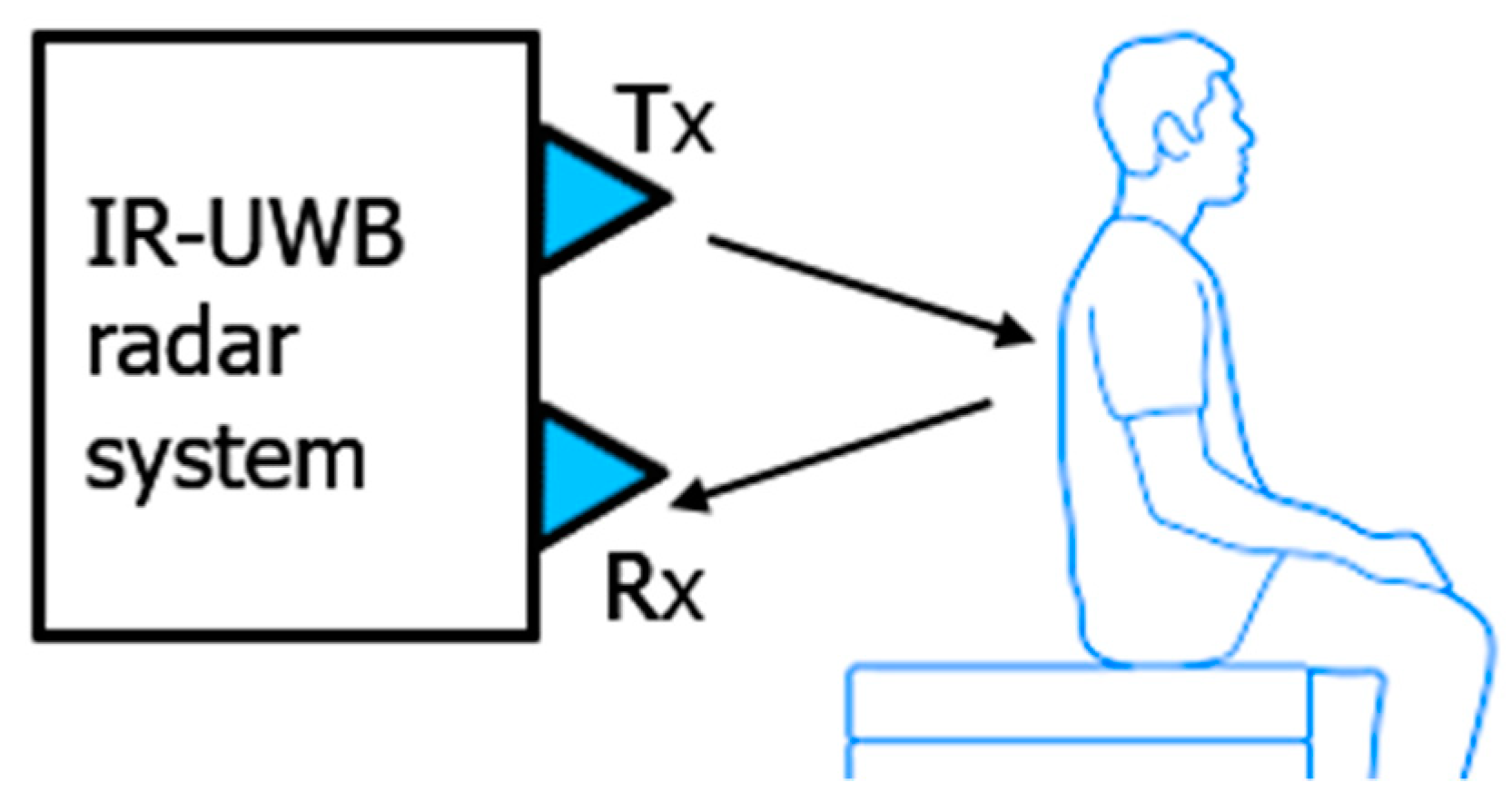
4.1. Experimental Setup

In this section, the hardware and software setup as well as the subjects involved in the experiments are discussed.

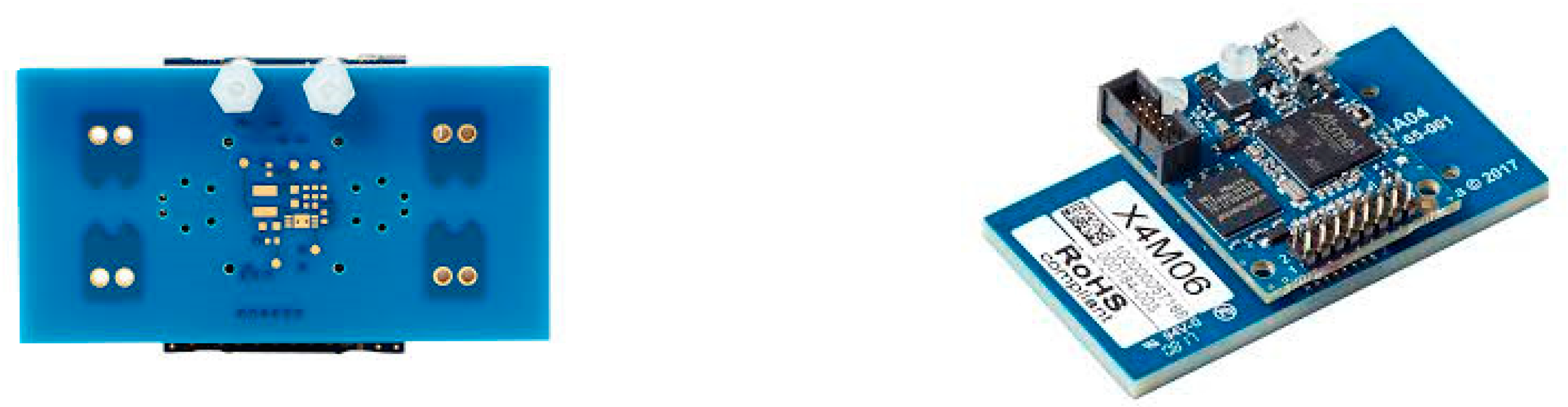
4.1.1. Hardware and Software Setup

In this work, we have used IR-UWB sensor modules Xethru X4, from Novelda, Norway (Figure 10).
This sensor module is a system on chip radar as it has the signal generator, external memory, transmitter and receiver antenna and other necessary components available on one chip. A Gaussian derivative pulse is used for the transmitting signal. The radar module may be driven by a PC or a microcontroller, using different software such as MATLAB, Python or Microchip Studio. In this work, we have connected it to a PC and used MATLAB software for data acquisition. The most important parameters of the radar module are listed in Table 1.
According to the experimental setup for data acquisition shown in Figure 11, the radar sensor is deployed at the backside of the human body.
The transmitted radar impulse signals are reflected by the human back and contain the information related to the motion caused by the human heart beats. After sampling the received signal and averaging it to increase the SNR, a bandpass filter is applied to remove the out of band noise from the backscattered signal. The filtered signals are then stored in the PC through a micro-USB cable. The distance of the human to the radar sensor is kept between 0.5 and 1 m due to the targeted application because in a typical vehicle the distance between the driver and the rear seat may be less than a meter. To prove the robustness of the algorithm, experiments were carried out in different conditions. During the experiments, the subjects were resting for most of the time and also talking and slightly moving their bodies for certain time intervals.

4.1.2. Subjects Involved in the Experiments

All the subjects involved in these experiments participated voluntarily. Both male and female human subjects were considered for the experiments. The list of five subjects involved in the experiments for this work is presented in Table 2.
All of the participants were healthy and without any special health conditions or disabilities.

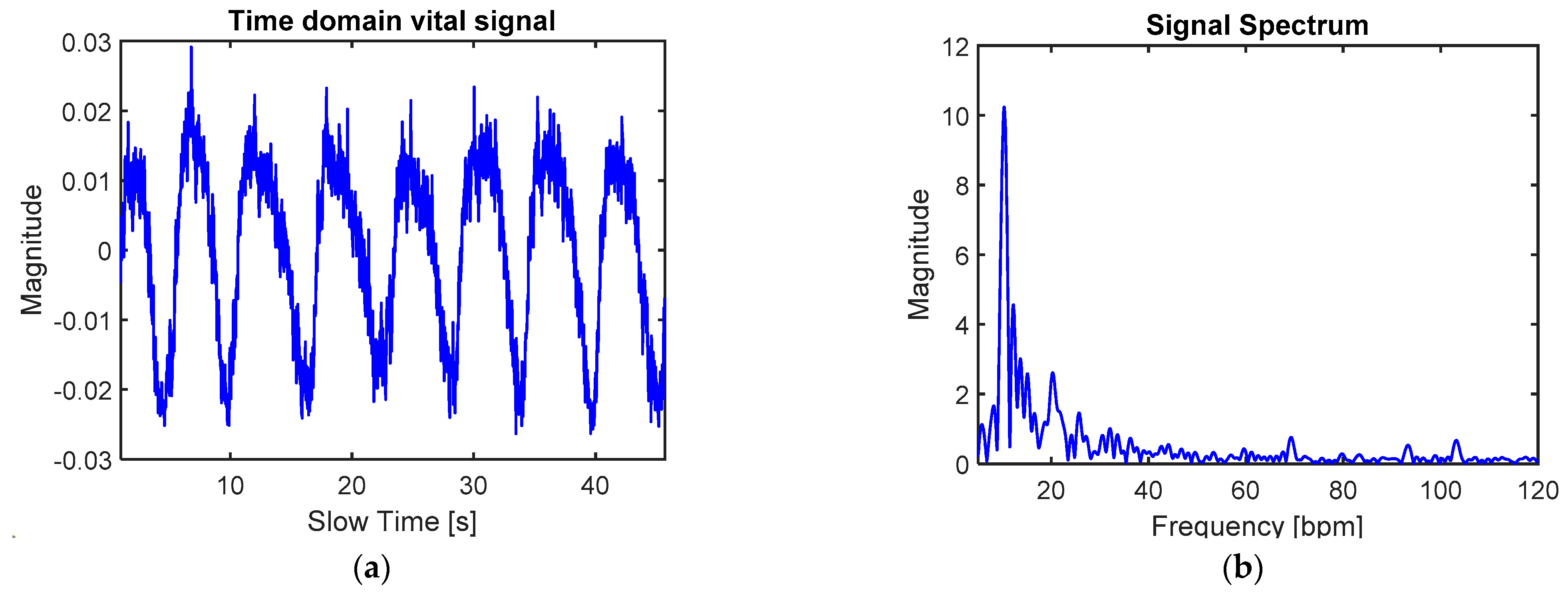
4.2. Signal Processing and HR Results

The signal is first passed through a clutter removal filter. The results of the vital signal extracted from different subjects after the clutter removal filter are given in Figure 12.
The red dots represent the peaks extracted using the local peak detection algorithm as discussed in the algorithm section of the paper. In Figure 12a–c, the signals correspond to the body in the resting condition, while in Figure 12d, the encircled part of the vital signal represents the random body motion (RBM). During the RBM, the acquired vital signal is corrupted by the huge motion of the body; however, the peak detection algorithm alone cannot differentiate it from the normal resting vital signal. Therefore, a deep learning-based method is used in this work to perform this classification task as explained below.
From the above vital signals, we extract images in grayscale as discussed in Section 3.1 and then the CNN is used for feature extraction. It may be noted that the input size of the AlexNet is 227 × 227 × 3, whereas the grayscale image of our database is 50 × 50. In order to convert the size of our input images to the AlexNet, we have used the MATLAB function for augmenting the image data. The output image size is specified as 227 × 227 and the color preprocessing option is selected as gray to RGB which will convert the grayscale image into a three-dimensional RGB image. The SVM followed by CNN is used for one-class classification or anomaly detection. The patterns that give a high score of SVM output matches the usual patterns used for training, while those patterns which are abnormal will give a lower score. The hyperparameters of the SVM were optimized by using the HHO. HHO algorithm [38] is a meta-heuristic optimization technique proposed in 2019 [39], which adopts a multi-strategy to update the population position and during the iterative process it is able to maintain the population diversity to the maximum extent possible, resulting in a good convergence. It performs better than the traditional metaheuristic optimization approaches such as particle swarm and genetic algorithms. In this work, a total of 2500 images were used for training and testing of the network, and then pre-trained AlexNet and SVM were employed to extract the features and classify the patterns. The example in Figure 13 shows the two patterns and their respective scores compared to the threshold.
As shown in Figure 13, the normal vital signal and the signal corrupted by RBM or any other external factors yield different accuracy scores. The signal segment in Figure 13a represents normal vital signal pattern and thus the accuracy score is greater than the threshold, while the signal segment in Figure 13b represents corrupted signal and hence the accuracy score is less than the experimentally set threshold value. This method validates the short duration segments of the signal and therefore it can detect and very effectively remove the RBM or another interference signal for a very short duration.
As discussed in Section 3.3, the heart rate values were extracted from the duration of the segments. The mean value of the segments that result in a good accuracy score was calculated. In order to compare the extracted and actual HR values, we have used the gold standard device for the HR measurement, i.e., the ECG. The ECG module PSL-iECG2 was used as a benchmark device. It uses low voltage (5 V) and the current consumption is also very low, i.e., 50 mA. The CNN layers for the feature extraction were selected based on the accuracy results shown in Table 3. By increasing the depth of the CNN architecture of AlexNet, the accuracy increases. However, at Conv4, it almost reached the steady state, so this layer was selected as the optimal depth of the AlexNet architecture in this work.
For the classification accuracy determination, the vital signal was measured under a resting condition as well as motion condition. Five volunteers were involved in the experiments and the vital signal was measured for a duration of 1 min for each individual. These experiments were repeated 20 times for each individual to gather a large amount of training data for the neural network. The artifact parts of the experiments were monitored manually so that the experiment timing may be divided into stationary (when the human is resting) and non-stationary (when the human is performing some body motions). The overall dataset comprised 2500 images. In total, 60% of the images were used for training and 40% were used for validation. In the validation part, both normal and outlier (stationary and non-stationary in this case) images were stored. If the model output matched the true value, then it was considered a correct decision, otherwise it was considered an inaccurate decision by the classifier. Since our work is related to the accurate HR monitoring, the important metric is accuracy. We have evaluated the performance of the model based on the classification accuracy. The accuracy results are shown in Table 3.
Table 3. shows that the classification accuracy converges after the fourth convolution layer. Therefore, the features of the AlexNet were extracted after the fourth layer.
The average error of the proposed algorithm with respect to the benchmark ECG sensor was calculated for the experiment performed on the five individual subjects. The time duration of 5 min was selected for the better evaluation of the proposed algorithm. The non-stationary scenarios were randomly performed during the experiments. Although the overall error rate depends on the time length of the non-stationary signal length. However, for the same experiments, where the non-stationary signal length is same, the error is dependent on the selection of the CNN layers, as shown in Table 4.
Table 4 shows that the minimum error rate is achieved at Conv4, so it is better to extract a feature at this layer as the algorithm already achieves the steady state and adding further layers will result in more memory and time complexity without a significant improvement in the accuracy.

5. Conclusions and Future Work

In this paper, we have proposed an algorithm for robust heart rate detection. Since current technology is limited with regards to vital sign measurement in challenging conditions such as body movement, this approach may prove very useful as it accurately detects the heart rate under movement conditions. In this work, real signals from a commercial IR-UWB radar sensor were used for the validation of the algorithms. The vital signal was segmented using peak detection and then deep learning-based classification was applied to find out whether the segment refers to the heart rate pattern or noisy pattern. The experiments were performed inside a standing car. The radar was placed at the back side of the human, at a few centimeters distance. The results were promising when compared to the ECG sensor results. The summary of the main achievements of this work is given as follows.
  • We propose an algorithm based on time series data, which is the original vital signal, instead of converting it into frequency domain.
  • We have determined an optimal location for radar sensor, so that the radar signal is least affected by the interference from RBM and other external interfering movements inside the car.
  • A deep learning classifier is used to detect the pattern of the heart rate signal.
  • The methods proposed in this work have a better performance than state-of-the-art algorithms on real data.
Our future goal is to deploy this radar behind the driver’s seat to develop specific algorithms to compensate for the low SNR due to the through-the-seat setting of the radar sensor.

Author Contributions

F.K. performed the experimental work, algorithms design and wrote the paper. S.A. helped in the supervision of the experimental design and paper writing. R.Y. participated at all stages of the paper, i.e., during experimental stage, algorithm development and paper writing and formatting. P.M. helped in the development of the idea for the research work and the experimental section of the paper. He also gave suggestions at all the stages of the research work. E.R. supervised the whole process of the research work. E.R. also helped to secure the funding for the research work and the publication-related costs. All authors have read and agreed to the published version of the manuscript.

Funding

This research has received funding from the European Union’s Horizon 2020 research and innovation program under the Marie Sklodowska-Curie grant agreement No 838037. The content of this paper only reflects the authors’ views and the Research Executive Agency is not responsible for any use that may be made of the information it contains.

Informed Consent Statement

All the participants took part in the experiments voluntarily and with full information about the procedures and objectives of the experiments and they were free to withdraw from the experiments at any time during the experiments.

Data Availability Statement

Please contact the corresponding author for the data associated with this work.

Acknowledgments

We acknowledge the reviewers for taking their time to review our work.

Conflicts of Interest

The authors declare no conflict of interest.

References

  1. Chioukh, L.; Boutayeb, H.; Deslandes, D.; Wu, K. Noise and sensitivity of harmonic radar architecture for remote sensing and detection of vital signs. IEEE Trans. Microw. Theory Tech. 2014, 62, 1847–1855. [Google Scholar] [CrossRef]
  2. Lin, J.C. Microwave sensing of physiological movement and volume change: A review. Bioelectromagnetics 1992, 13, 557–565. [Google Scholar] [CrossRef] [PubMed]
  3. Lauteslager, T.; Maslik, M.; Siddiqui, F.; Marfani, S.; Leschziner, G.D.; Williams, A.J. Validation of a New Contactless and Continuous Respiratory Rate Monitoring Device Based on Ultra-Wideband Radar Technology. Sensors 2021, 21, 4027. [Google Scholar] [CrossRef] [PubMed]
  4. Su, W.-C.; Tang, M.-C.; El Arif, R.; Horng, T.-S.; Wang, F.-K. Stepped-frequency continuous-wave radar with self-injection-locking technology for monitoring multiple human vital signs. IEEE Trans. Microw. Theory Tech. 2019, 67, 5396–5405. [Google Scholar] [CrossRef]
  5. Li, K.L.; Lai, S.-H.; Cheng, K.; Henrickson, L.; Chen, I.; Wu, V.; Chen, J. Exercise vital signs detection employing fmcw radar and artificial neural networks. In Proceedings of the CLEO: Applications and Technology 2021, San Jose, CA, USA, 9–14 May 2021. [Google Scholar]
  6. Chen, W.; Lan, S.; Zhang, G. Multiple-target vital signs sensing using 77GHz FMCW radar. In Proceedings of the 15th European Conference on Antennas and Propagation (EuCAP), Düsseldorf, Germany, 22 March 2021; pp. 1–3. [Google Scholar]
  7. Su, G.; Petrov, N.; Yarovoy, A. Dynamic Estimation of Vital Signs with mm-wave FMCW Radar. In Proceedings of the 2020 17th European Radar Conference (EuRAD), Utrecht, The Netherlands, 13–15 January 2021; pp. 206–209. [Google Scholar]
  8. Wang, G.; Munoz-Ferreras, J.-M.; Gu, C.; Li, C.; Gomez-Garcia, R. Application of linear-frequency-modulated continuous-wave (LFMCW) radars for tracking of vital signs. IEEE Trans. Microw. Theory Tech. 2014, 62, 1387–1399. [Google Scholar] [CrossRef]
  9. Lazaro, A.; Girbau, D.; Villarino, R. Analysis of vital signs monitoring using an IR-UWB radar. Prog. Electromagn. Res. 2010, 100, 265–284. [Google Scholar] [CrossRef] [Green Version]
  10. Khan, F.; Ghaffar, A.; Khan, N.; Cho, S.H. An overview of signal processing techniques for remote health monitoring using impulse radio UWB transceiver. Sensors 2020, 20, 2479. [Google Scholar] [CrossRef]
  11. Khan, F.; Azou, S.; Youssef, R.; Morel, P.; Radoi, E.; Dobre, O.A. An IR-UWB multi-sensor approach for collision avoidance in indoor environments. IEEE Trans. Instrum. Meas. 2022, 71, 1–13. [Google Scholar] [CrossRef]
  12. Khan, F.; Leem, S.K.; Cho, S.H. Human–computer interaction using radio sensor for people with severe disability. Sens. Actuators A Phys. 2018, 282, 39–54. [Google Scholar] [CrossRef]
  13. Ahmed, S.; Cho, S.H. Hand gesture recognition using an IR-UWB radar with an inception module-based classifier. Sensors 2020, 20, 564. [Google Scholar] [CrossRef] [Green Version]
  14. Khan, F.; Leem, S.K.; Cho, S.H. In-air continuous writing using uwb impulse radar sensors. IEEE Access 2020, 8, 99302–99311. [Google Scholar] [CrossRef]
  15. Leem, S.K.; Khan, F.; Cho, S.H. Detecting mid-air gestures for digit writing with radio sensors and a CNN. IEEE Trans. Instrum. Meas. 2019, 69, 1066–1081. [Google Scholar] [CrossRef]
  16. Khan, N.; Khan, K.; Khan, A.; Alam, I.; Khan, F.U.; Khan, S.U.; Ali, A. Accommodate Data Loss in Monitoring Vital Signs Through Autoregressive Model. J. Med. Imaging Health Inform. 2019, 9, 1205–1214. [Google Scholar] [CrossRef]
  17. Khan, F.; Choi, J.W.; Cho, S.H. Design issues in vital sign monitoring through IR UWB radar. In Proceedings of the 18th IEEE International Symposium on Consumer Electronics (ISCE 2014), Jeju, South Korea, 22–25 June 2014; pp. 1–2. [Google Scholar]
  18. Liu, S.; Qi, Q.; Cheng, H.; Sun, L.; Zhao, Y.; Chai, J. A Vital Signs Fast Detection and Extraction Method of UWB Impulse Radar Based on SVD. Sensors 2022, 22, 1177. [Google Scholar] [CrossRef]
  19. Paterniani, G.; Sgreccia, D.; Davoli, A.; Guerzoni, G.; di Viesti, P.; Valenti, A.C.; Vitolo, M.; Vitetta, G.M.; Boriani, G. Radar-based Monitoring of Vital Signs: A Tutorial Overview. TechRxiv 2022, preprint. [Google Scholar] [CrossRef]
  20. Fallatah, A.; Bolic, M.; MacPherson, M.; la Russa, D.J. Monitoring Respiratory Motion during VMAT Treatment Delivery Using Ultra-Wideband Radar. Sensors 2022, 22, 2287. [Google Scholar] [CrossRef]
  21. Yen, H.T.; Kurosawa, M.; Kirimoto, T.; Hakozaki, Y.; Matsui, T.; Sun, G. A medical radar system for non-contact vital sign monitoring and clinical performance evaluation in hospitalized older patients. Biomed. Signal Process. Control. 2022, 75, 103597. [Google Scholar] [CrossRef]
  22. Choi, I.; Kim, M.; Choi, J.; Park, J.; Park, S.; Kim, K. Robust cardiac rate estimation of an individual. IEEE Sens. J. 2021, 21, 15053–15064. [Google Scholar] [CrossRef]
  23. Rohman, B.P.; Andra, M.B.; Nishimoto, M. Through-the-Wall human respiration detection using UWB impulse radar on hovering drone. IEEE J. Sel. Top. Appl. Earth Obs. Remote Sens. 2021, 14, 6572–6584. [Google Scholar] [CrossRef]
  24. Yang, X.; Zhang, X.; Ding, Y.; Zhang, L. Indoor Activity and Vital Sign Monitoring for Moving People with Multiple Radar Data Fusion. Remote Sens. 2021, 13, 3791. [Google Scholar] [CrossRef]
  25. Regev, N.; Wulich, D. Remote sensing of vital signs using an ultra-wide-band radar. Int. J. Remote Sens. 2019, 40, 6596–6606. [Google Scholar] [CrossRef]
  26. Regev, N.; Wulich, D. Multi-modal, remote breathing monitor. Sensors 2020, 20, 1229. [Google Scholar] [CrossRef] [PubMed] [Green Version]
  27. Yang, M.; Yang, X.; Li, L.; Zhang, L. In-car multiple targets vital sign monitoring using location-based vmd algorithm. In Proceedings of the 2018 10th International Conference on Wireless Communications and Signal Processing (WCSP), Hangzhou, China, 18–20 October 2018; pp. 1–6. [Google Scholar]
  28. Khan, F.; Leem, S.K.; Cho, S.H. Hand-based gesture recognition for vehicular applications using IR-UWB radar. Sensors 2017, 17, 833. [Google Scholar] [CrossRef]
  29. Choi, J.W.; Nam, S.S.; Cho, S.H. Multi-human detection algorithm based on an impulse radio ultra-wideband radar system. IEEE Access 2016, 4, 10300–10309. [Google Scholar] [CrossRef]
  30. Leem, S.; Khan, F.; Cho, S. Vital sign monitoring and mobile phone usage detection using IR-UWB radar for intended use in car crash prevention. Sensors 2017, 17, 1240. [Google Scholar] [CrossRef] [PubMed] [Green Version]
  31. Yang, Z.; Bocca, M.; Jain, V.; Mohapatra, P. Contactless breathing rate monitoring in vehicle using UWB radar. In Proceedings of the 7th international workshop on real-world embedded wireless systems and networks, Shenzhen, China, 4 November 2018; pp. 13–18. [Google Scholar]
  32. Sahu, M.; Dash, R. A Survey on deep learning: Convolution Neural Network (CNN). In Intelligent and Cloud Computing; Springer: Berlin/Heidelberg, Germany, 2021; pp. 317–325. [Google Scholar]
  33. Lavanya, P.; Sasikala, E. Deep learning techniques on text classification using Natural Language Processing (NLP) in social healthcare network: A comprehensive survey. In Proceedings of the 2021 3rd International Conference on Signal Processing and Communication (ICPSC), Coimbatore, India, 13–14 May 2021; pp. 603–609. [Google Scholar]
  34. Ahmed, S.; Khan, F.; Ghaffar, A.; Hussain, F.; Cho, S.H. Finger-counting-based gesture recognition within cars using impulse radar with convolutional neural network. Sensors 2019, 19, 1429. [Google Scholar] [CrossRef] [Green Version]
  35. Leem, S.K.; Khan, F.; Cho, S.H. Remote authentication using an ultra-wideband radio frequency transceiver. In Proceedings of the 2020 IEEE 17th Annual Consumer Communications & Networking Conference (CCNC), Las Vegas, NV, USA, 10–13 January 2020; pp. 1–8. [Google Scholar]
  36. Cristianini, N.; Shawe-Taylor, J. An Introduction to Support Vector Machines and Other Kernel-Based Learning Methods; Cambridge University Press: Cambridge, UK, 2000. [Google Scholar]
  37. Schölkopf, B.; Smola, A.J.; Bach, F. Learning with Kernels: Support Vector Machines, Regularization, Optimization, and Beyond; MIT Press: Cambridge, MA, USA, 2002. [Google Scholar]
  38. Heidari, A.A.; Mirjalili, S.; Faris, H.; Aljarah, I.; Mafarja, M.; Chen, H. Harris hawks optimization: Algorithm and applications. Future Gener. Comput. Syst. 2019, 97, 849–872. [Google Scholar] [CrossRef]
  39. Gogna, A.; Tayal, A. Metaheuristics: Review and application. J. Exp. Theor. Artif. Intell. 2013, 25, 503–526. [Google Scholar] [CrossRef]
Figure 1. System overview.
Electronics 11 02505 g001
Figure 2. Raw signal received from a human target (a) before and (b) after clutter removal filter.
Electronics 11 02505 g002
Figure 3. (a) Time domain vital signal; (b) FFT of the vital signal.
Electronics 11 02505 g003
Figure 4. Block diagram of signal segmentation and HR detection process.
Electronics 11 02505 g004
Figure 5. Peaks detected from vital signal reflected from human backside.
Electronics 11 02505 g005
Figure 6. Heart rate patterns extracted for four consecutive peaks: (a) direct plot of the pattern; (b) image transformation into grayscale image for CNN features extraction.
Electronics 11 02505 g006
Figure 7. AlexNet architecture for feature extraction.
Electronics 11 02505 g007
Figure 8. Block diagram of the system for feature extraction and one-class classification.
Electronics 11 02505 g008
Figure 9. Histogram of heart rate interval values (a) before and (b) after applying the proposed algorithm for the removal of noisy peaks from the received vital signal.
Electronics 11 02505 g009
Figure 10. Novelda IR-UWB radar sensor (X4).
Electronics 11 02505 g010
Figure 11. Experimental setup for data acquisition.
Electronics 11 02505 g011
Figure 12. Vital signal obtained from multiple subjects. Normal resting position (ac) and resting and RBM signal (d).
Electronics 11 02505 g012
Figure 13. Pattern classified by SVM as HR (a) or anomaly pattern (b) based on accuracy score.
Electronics 11 02505 g013
Table 1. Radar module parameters.
ParametersValue
Output power−12.6 dBm
Center frequency8.748 GHz
Pulse repetition frequency40 MHz
Bandwidth (−10 dB)2.95 GHz
Range resolution6.4 mm
Beamwidth65°
Sampling frequency23.3 GHz
No. of antenna arrays per radar chip1 Tx & 1 Rx
Table 2. Details of participants.
GenderAge (Years)Height (cm)Weight (kg)
M3318272
M2117373
M2817477
F2617060
M2416562
Table 3. Classification accuracy vs. CNN layers.
CNN LayersAverage Accuracy
Conv164.3%
Conv278.6%
Conv389.5%
Conv497.4%
Conv597.4%
Table 4. Average HR error.
CNN LayersAverage Error
Conv119.78%
Conv212.40%
Conv36.95%
Conv42.31%
Conv52.32%
Publisher’s Note: MDPI stays neutral with regard to jurisdictional claims in published maps and institutional affiliations.

