Article

Design and Analysis of Magnetic Shielding Mechanism for Wireless Power Transfer System Based on Composite Materials

Tianjin Key Laboratory of Electrical Equipment Intelligent Control, Tiangong University, Tianjin 300387, China
*
Author to whom correspondence should be addressed.
Electronics 2022, 11(14), 2187; https://doi.org/10.3390/electronics11142187
Submission received: 18 June 2022 / Revised: 7 July 2022 / Accepted: 11 July 2022 / Published: 12 July 2022

Abstract

:
In a wireless power transfer (WPT) system, in order to reduce the leakage of the magnetic field in the space and to improve the transmission efficiency of the system, a magnetic shielding mechanism is usually added to the coupling coil. However, the commonly used ferrite material has defects of brittleness, easy cracking, and a low saturation limit. Therefore, a novel magnetic shielding mechanism based on a quartz fiber and nanocrystalline reinforced resin matrix composite material was proposed, and epoxy resin and cross-laminate-splicing processes were used to improve the resistivity of the nanocrystalline material and to improve the eddy current loss. A discretized geometric model was designed for quartz fiber, and the effects of different shielding structures on the space magnetic field and the power loss were simulated and analyzed. In the experiment, a space magnetic field measurement system was built, and the transmission efficiency was analyzed. The results showed that the new magnetic shielding mechanism has a good shielding effect, can effectively suppress leakage of the magnetic field in space, reduce the weight, and improve the mechanical performance while also achieving a high transmission efficiency of 85.6%.

1. Introduction

Wireless power transfer (WPT) technology is a noncontact power transmission technology realized in the air with the help of magnetic fields, electric fields, microwaves, and other soft media. Compared with traditional contact power transmission methods, WPT technology has the advantages of safety, reliability, flexibility, and convenience [1,2,3]. It has been widely used in many fields, such as electric vehicles [4], implantable medical devices [5], consumer electronics [6], and transportation [7]. Due to characteristics of high transmission efficiency, long transmission distance, and low requirement for directivity, magnetic coupling resonant wireless power transfer (MCR-WPT) technology is considered to be one of the greatest potential technologies in the application of medium-range WPT [8,9]. However, when energy is exchanged between the transmitting and receiving coils, leakage of the magnetic field is inevitably generated in the nonworking area. Therefore, a magnetic shielding mechanism is added to WPT systems to suppress the leakage of the magnetic field to protect the electromagnetic environment in the nonworking area [10,11].
In recent years, magnetic shielding mechanisms based on ferrite material have become one of the most commonly used methods to weaken electromagnetic radiation [12,13]. Ferrite can provide a high-permeability channel for the magnetic field generated by the coupled coil, which is beneficial to reduce leakage of the magnetic field around the coil [14,15]. Researchers are committed to improving the transmission efficiency of these system by optimizing the structure and arrangement of the ferrite. In reference [16], a shielding structure composed of nine strips of ferrite was designed, and the parameters of the ferrite were optimized. While improving the coupling coefficient between the coils, the weight of the shielding structure was also reduced. In subsequent research, a T-type structure was proposed. By adding ferrite to the mutual coupling area of the asymmetric circular coil to reduce the magnetic resistance in this area, the leakage of the magnetic field in the space was effectively weakened [17]. Aiming at the problem of increased loss caused by the uneven distribution of magnetic flux density in ferrite, a circular magnetic core structure was designed. Compared with results before the optimization, the core loss per unit volume could be reduced by 30%, which ensured the uniform distribution of the magnetic flux density [18].
However, in the above research projects, the optimized ferrite core structures were mostly special shapes, which are difficult to realize with processing technology in practice [19,20]. In addition, ferrite itself has some defects. First, it is brittle and prone to mechanical fracture. Moreover, the saturation magnetic flux density of ferrite is low, and the transmission efficiency may be reduced when applied in high-frequency and high-power applications. Furthermore, the magnetic properties of ferrite change drastically with an increase in temperature, which makes the design of magnetic shielding mechanisms more complicated [21,22]. In reference [23], in order to reduce the amount of the ferrite core and to improve the mechanical properties, a polymer based on ferrite particles was designed and fabricated. However, due to large eddy current losses, the transmission efficiency of the system was lower than that of a ferrite core of the same size.
With the continuous development of shielding materials, nanocrystals have been gradually used in the design of magnetic shielding mechanisms due to their superior performances [24,25]. They have high magnetic permeability and good mechanical properties, which can realize the miniaturization and light weight of magnetic shielding mechanisms [26]. However, since the resistivity of nanocrystals is much smaller than that of ferrite, serious eddy current loss and heat generation problems can occur when they are used alone. Therefore, it is necessary to optimize their design to eliminate these negative impacts on the system.
In order to improve the eddy current loss of nanocrystals and reduce the leakage of the magnetic field in space, this paper combines electromagnetic modeling and finite element analysis to analyze the wave transmittance of quartz fibers and the high resistivity of epoxy resin. Quartz fiber and nanocrystalline reinforced resin matrix composites are fabricated using a cross-laminate-splicing process, providing a mechanically stronger alternative to conventional, compact ferrite cores. While improving the energy transmission efficiency of the system, the weight of the magnetic shielding mechanism is also reduced, and the application range becomes wider.
This paper is composed of six sections. In Section 2, an equivalent circuit model of a WPT system based on an S/S compensation structure is established, and the influences of various parameters on the system transmission efficiency are analyzed. In Section 3, the defects of ferrite material are expounded, and the optimal design of the magnetic shielding mechanism is carried out. In Section 4, a discretized geometric modeling method is proposed for quartz fiber, and a finite element analysis of the shielding mechanism is carried out from the space magnetic field and the core loss. In Section 5, the quartz fiber and nanocrystal reinforced resin matrix composite material is fabricated, and the experimental platform is built. The results show that the new magnetic shielding mechanism has a good shielding effect and can effectively improve the transmission efficiency of the system. Section 6 is the conclusion of this paper.

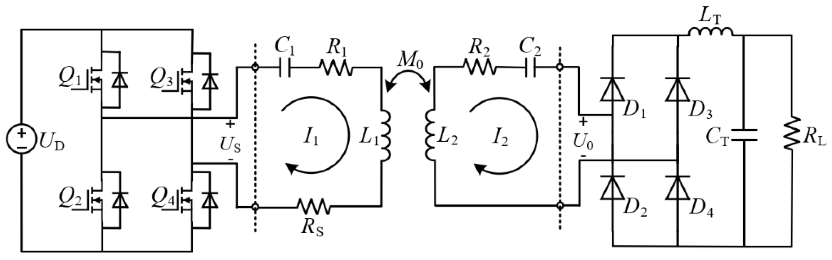
2. Theoretical Analysis of WPT System

In WPT systems, the S/S (series/series) topology compensation method is widely used. This structure has the advantages of simplicity, stable frequency, no mutual inductance or load change, and constant output voltage [27]. In order to study the influences of system parameters on the transmission efficiency considering the electromagnetic coupling relationship between the two coils, an equivalent circuit model of a WPT system based on the S/S compensation structure was established, as shown in Figure 1. The high-frequency inverter is composed of four MOSFETs (Q1Q4); UD is the DC input voltage source that supplies power to the inverter, and the output voltage is US. RS is the internal resistance of the power supply. L1 and L2 are the self-inductances of the transmitting coil and the receiving coil, respectively, and R1 and R2 are the corresponding coil resistances, respectively. C1 is the transmission-side compensation capacitor in the series with L1, and C2 is the reception-side compensation capacitor in the series with L2. M0 represents the mutual inductance between the transmitting coil and the receiving coil. I1 and I2 are the loop currents on the transmitter side and the receiver side, respectively. The full-bridge uncontrolled rectifier is composed of four diodes (D1D4); the input voltage is U0, and it is connected to the load RL through a filter circuit composed of LT and CT.
According to Kirchhoff’s voltage law (KVL), the equivalent equation of the circuit can be expressed as:
[ U S 0 ] = [ R S + R 1 + j X 1 j ω M 0 j ω M 0 R L + R 2 + j X 2 ] · [ I 1 I 2 ]
Among them are the transmitting coil impedance X1 = ωL1 − 1/ωC1, the receiving coil impedance X2 = ωL2 − 1/ωC2, and the resonant angular frequency ω = 2πf. When the resonant capacitance and coil inductance satisfy jωL + 1/jωC = 0, the system is in a resonant state, and the resonant frequency of the system can be changed by adjusting the capacitance value. According to Equation (1), I1 and I2 can be expressed as:
I 1 = ( R L + R 2 ) U S ( R S + R 1 ) ( R L + R 2 ) + ω 2 M 0 2
I 2 = j ω M 0 U S ( R S + R 1 ) ( R L + R 2 ) + ω 2 M 0 2
The input power of the system is as follows:
P in = U S I 1 = ( R 2 + R L ) U S 2 ( R S + R 1 ) ( R 2 + R L ) + ω 2 M 0 2
The output power of the system is as follows:
P out = I 2 2 R L = ( ω M 0 U S ) 2 R L [ ( R S + R 1 ) ( R 2 + R L ) + ω 2 M 0 2 ] 2
According to Equations (4) and (5), the transmission efficiency of the system can be obtained as:
η = ω 2 M 0 2 R L [ ( R S + R 1 ) ( R L + R 2 ) + ω 2 M 0 2 ] ( R L + R 2 )
Since the coupling coefficient is k = M0/(L1L2)1/2, by introducing k into Equation (6), η can be obtained as:
η = L 1 L 2 ω 2 R L [ ( R S + R 1 ) ( R L + R 2 ) k 2 + ω 2 L 1 L 2 ] ( R L + R 2 ) k 2
When the parameters of the coil are fixed, increasing RL or k increases η, but k is the quadratic of η, which has a greater impact on it. The relationship between M0 and the magnetic flux density B and coil area S is as follows:
M 0 = B S I 2
and η can also be expressed as:
η = R L ( R S + R 1 ) ( B S ) 2 U S L 1 L 2 ( j ω B S U S )
When the coil area S remains unchanged, the magnetic flux density B is a key indicator to measure the transmission efficiency of the system. The greater the value of the magnetic flux density between the coils, the higher the transmission efficiency of the system. When the magnetic shielding mechanism is added, the magnetic field distribution between the coupling mechanisms changes, and both k and B increase at this time, which is very beneficial to improve the transmission efficiency.

3. Design and Research of Magnetic Shielding Mechanism

3.1. Defects in Ferrite

Mn-Zn soft ferrite as a power ferrite has low cost, high resistivity, and low coercivity and magnetic loss, so it is widely used in the design of shielding structures. The relative permeability of the Mn-Zn ferrite selected in this paper was 3300, and the maximum magnetic saturation limit was 0.53 T. It is generally used in the frequency range of tens to hundreds of KHz.
Due to the nonlinear magnetic properties of ferrite, as the strength of the external magnetic field increases, the magnetic permeability gradually decreases. Therefore, in applications of high power and small volume, ferrite easily reaches magnetic saturation. At this stage, the increase in fast-charging devices means that the system needs to transmit more power at the same time. The coil excites a stronger alternating magnetic field, resulting in an increase in the magnetic induction intensity, and the ferrite is more prone to magnetic saturation. When the loss and heat increase, the coupling effect between the coils is also weakened. In addition, ferrite is a brittle material, and it is easy to damage the magnetic core structure due to bumps or impacts, resulting in the detuning of the system. In addition, the gap at the splicing also generates a leakage in the magnetic field, which further affects the overall performance of the system.

3.2. Research on New Magnetic Shielding Mechanism

Based on the many problems of ferrite shielding, this paper adopts iron-based nanocrystalline materials with high saturation limits, high magnetic permeabilities, and good mechanical properties, replacing the ferrite cores in wireless charging with lighter-weight materials with better mechanical properties. Although nanocrystals have excellent magnetization properties, the applicable frequencies are in MHz, and their resistivity is much smaller than that of ferrite. When high-frequency and high-power applications, such as the wireless charging of electric vehicles, are used, the heating problem is serious, and the transmission efficiency is greatly reduced. Therefore, it is necessary to optimize the process of the nanocrystalline magnetic core to improve its resistivity to alleviate the negative impact of eddy current loss on transmission efficiency.
Composite materials are new materials that are optimized using modern preparation technology to combine materials of different properties, which not only maintains the advantages of the performance of each component material but also obtains comprehensive properties that cannot be achieved with a single material. Aiming at the shortcomings of nanocrystals with low resistivity and large eddy current loss at high frequencies, a quartz fiber and nanocrystal reinforced resin matrix composite material was designed as a magnetic shielding mechanism. Among them, epoxy resin was used as an insulating material and was covered on the surface of the shielding structure after being pressed at a high temperature, which could improve the resistivity of the nanocrystalline material. As a high-performance inorganic fiber, quartz fiber is widely used in the reinforcement systems of various composite materials. Its excellent dielectric properties can make more magnetic lines of force pass through the nanocrystals, and it displays a good wave-transmitting effect.
From a macroscopic level, nanocrystalline tapes with a thickness of 25 μm were spliced in a cross-laminated manner, as shown in Figure 2, and the splicing gap further blocked the eddy current on the shielding surface. A three-dimensional orthogonal stacking method was adopted between the layers, which not only limited the eddy current in the vertical direction but also reduced the spatial leakage of the magnetic field generated by the splicing gap. A single 0.405 mm thick nanocrystalline magnetic core was an insulating layer of 5 μm between the layers, and it was covered by a polyester film. Composite material made using this method has excellent properties, such as corrosion resistance, fatigue resistance, and easy processing and forming, and it is more widely used than ferrite shielding.

4. Simulation Analysis

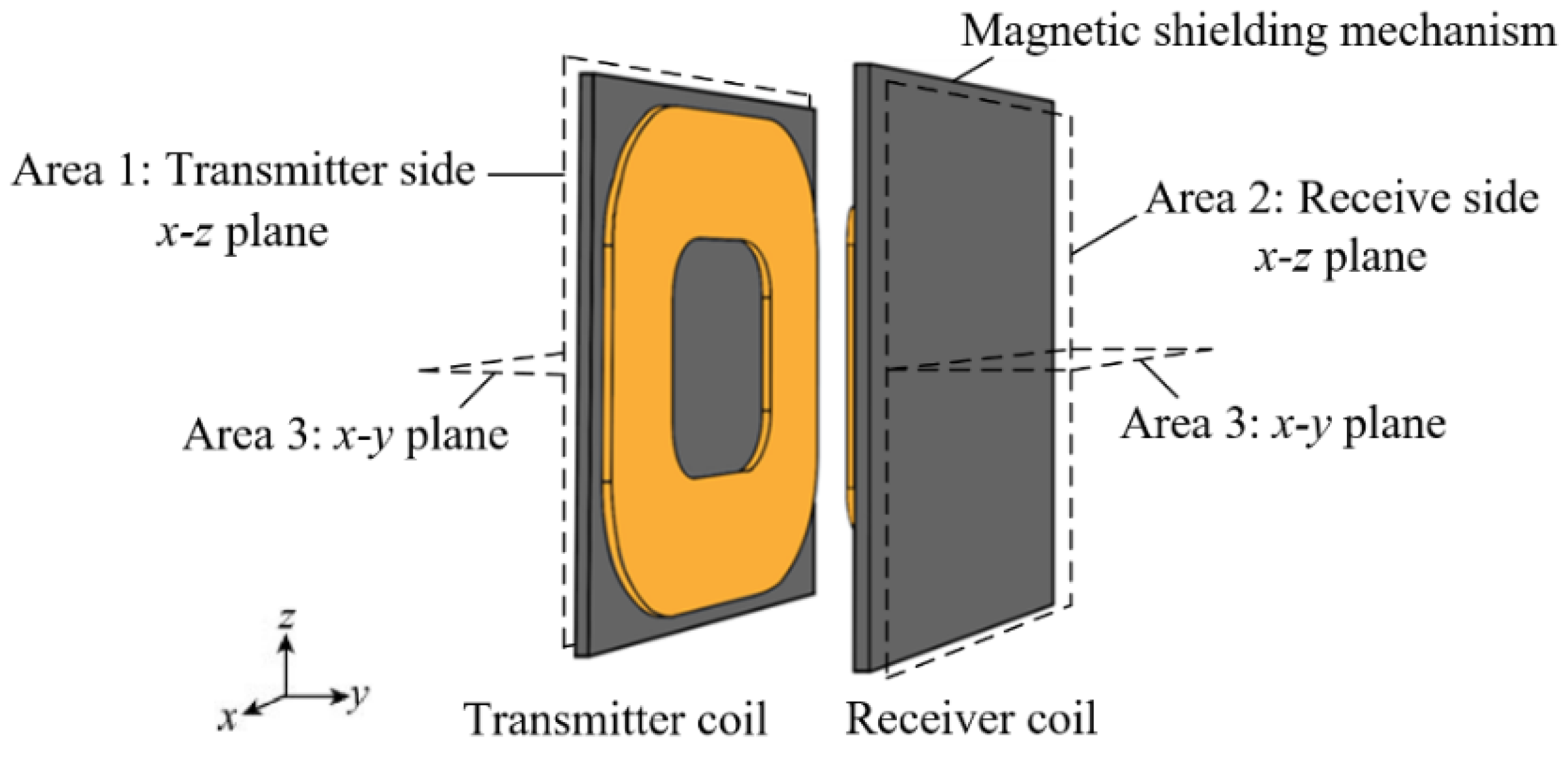
4.1. Coupling Mechanism Model

This paper used COMSOL for the simulation analysis. At present, there are many types of coupling mechanisms in WPT systems, mainly including single D type, DD type, and DDQ type for static wireless charging, as well as E type and C type coupling coils for dynamic wireless charging. Since the single D-type coupling structure can not only transmit more power but also generate a more uniform magnetic field, a single D type coupling mechanism with a magnetic shielding structure, as shown in Figure 3, was designed in this paper. Area 1–Area 3 are the x–z plane on the transmitting side, the x–z plane on the receiving side, and the x–y plane passing through the geometric center, respectively.
The resonant frequency of the entire system was 85 kHz, and the magnetic shield was covered behind the coupling mechanism. Under the circumstance that the shielding effect was not much different, the circular shielding occupied more space, and the weight increased, so the shielding adopted square shielding. To simplify the finite element analysis, a Litz coil was modeled as a multistrand lumped coil in the simulation. The main parameters of the coupling mechanism are shown in Table 1.

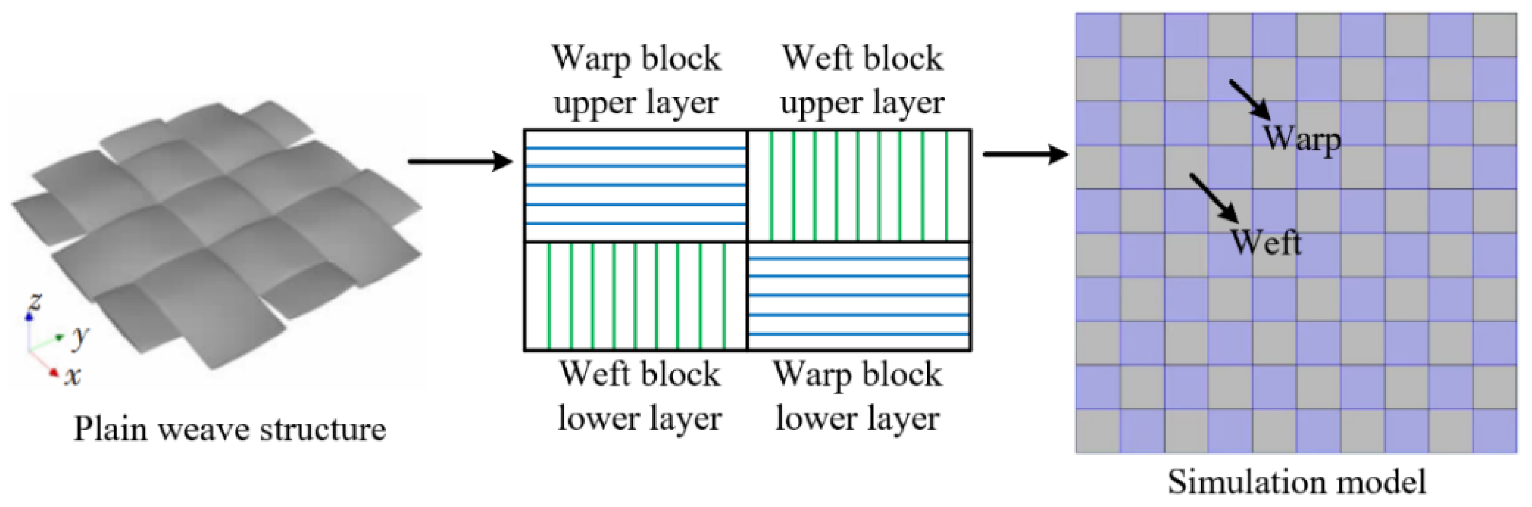
4.2. Quartz Fiber Model

As an important component of the composite materials, it was necessary to model and study quartz fibers. Quartz fibers are mainly woven in two groups of yarn at one interval and one through. The equivalent layer model is often used for analysis [28,29]. Due to the complex geometry of this plain-weave structure, the fibers in the warp and weft yarns have different directions, interweave with each other, and are distributed in the upper and lower layers so that the parameters in the same layer cannot be unified.
In order to better solve this problem, this paper proposed a discrete model applicable to a plain-weave structure under the premise of reasonably neglecting the warp and weft yarn bending due to weaving. The modeling method is shown in Figure 4. A three-dimensional anisotropic quartz fiber plain-weave structure was used as the basic unit in the model, and the parameter values of the basic unit were set in the contact part between the warp and weft yarns according to the fiber interlayer modeling method to realize the simplification of the finite element geometry modeling.

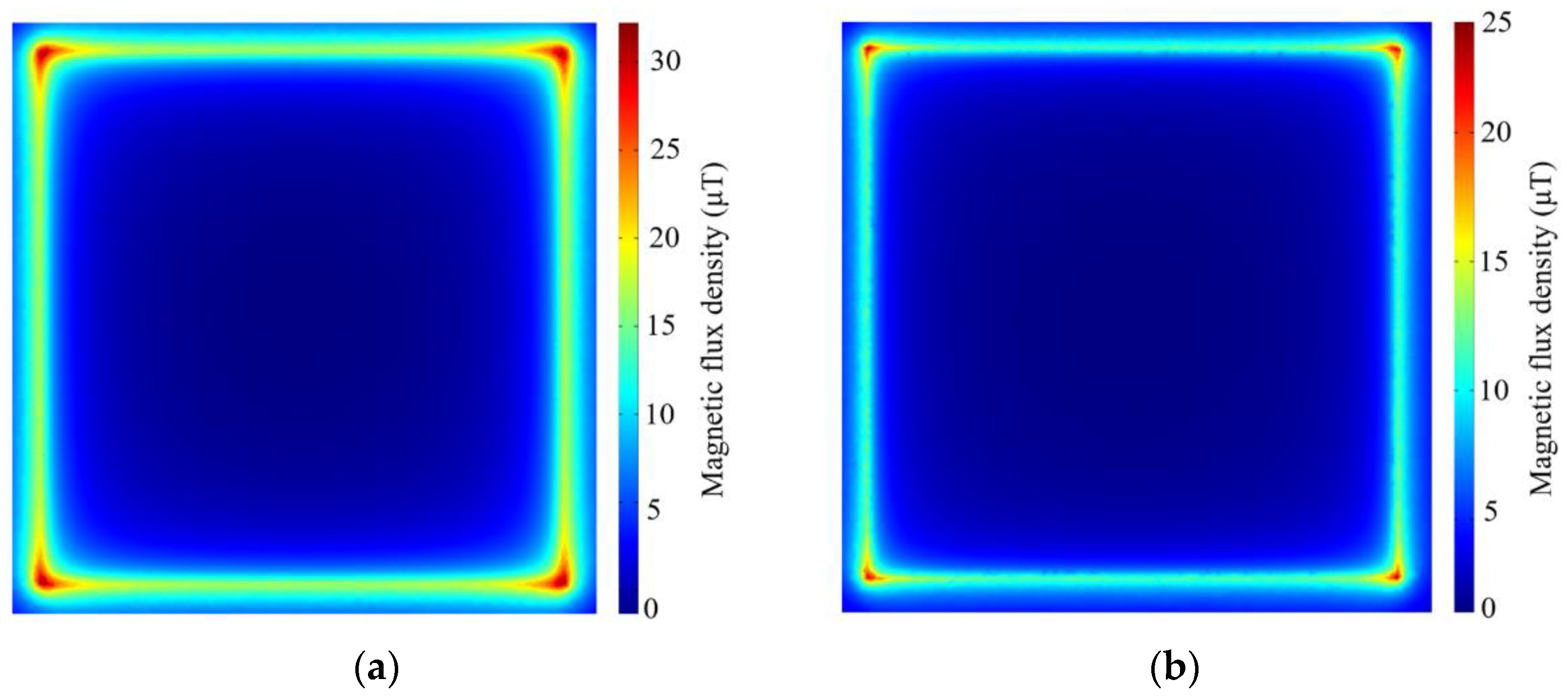
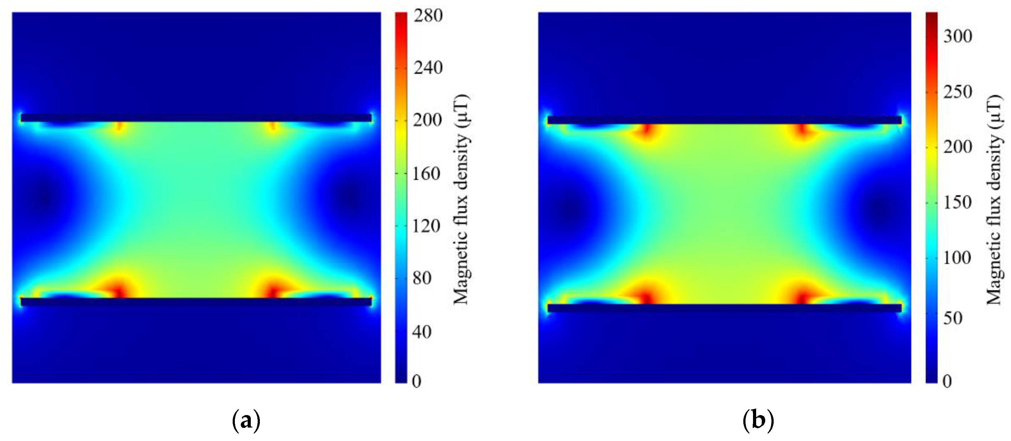
4.3. Magnetic Shielding Research

Table 2 shows the simulation results of the changes in the self-inductance and mutual inductance of the coil after the addition of the magnetic shield. It can be seen that the magnetic shielding increased the self-inductance and mutual inductance of the coil, especially after using the composite material. The self-inductance, mutual inductance, and coupling coefficient of the coil were further improved compared with the ferrite shielding and were increased by 3.12 μH, 1.27 μH, and 0.007, respectively, which could effectively improve the energy transmission efficiency of the system.
Figure 5 shows the simulation results of the magnetic field distribution in the x–z plane on both the transmitting side and the receiving side when the ferrite shield was added. From Figure 5a,b, in the case of transmission power of 2 KW, it can be seen that the magnetic flux density in the center part of the whole x–z plane was the smallest, the magnetic flux density increased gradually from the middle to the surroundings, and the maximum values appeared in the four corners of the whole plane. Among them, the maximum flux density on the transmitting side was 32.4 μT, and the maximum flux density on the receiving side was 25.2 μT, which was due to the edge effect caused by the large number of magnetic lines gathering at the edges of the ferrite when passing through it. This phenomenon led to excessive leakage of the magnetic field in the shielding edge space and exceeded the limit of 27 μT specified in ICNIRP2010, which may not achieve satisfactory shielding effects in some applications with high shielding requirements.
Figure 6 shows the magnetic field distribution in the x–z plane of the transmitting side and the x–z plane of the receiving side after the addition of the quartz fiber and nanocrystal reinforced resin matrix composite material shield. The magnetic flux densities on the transmitting side and the receiving side after adding the composite material were significantly reduced compared to the ferrite shielding, with maximum values of 25.4 μT and 19 μT, respectively, which were reduced by 7 μT and 6.2 μT, respectively. It can be seen in Figure 6a,b, similar to the case of the ferrite shielding, that the magnetic fields on the x–z plane of the transmitting side and the receiving side were also smaller in the middle, and the flux density was larger closer to the edge. However, the leakage of the magnetic field in the edge space became smaller, indicating that the quartz fiber had a good wave-transmitting effect and the more magnetic lines of force would pass through the low-reluctance nanocrystalline material, making the edge effect significantly weaker.
The spatial magnetic field distribution in the x–y plane when the coupling mechanism worked under different shielding structures is shown in Figure 7. From the simulation results, it can be seen that the magnetic flux density near the transmitting side was larger, the receiving side was smaller, and the magnetic shielding mechanism played a good role in binding the spatial magnetic field. The main magnetic flux in the working area was basically bound between the coupling mechanisms, and the leakage of the magnetic field in the nonworking area outside the shield was very small. After adding the composite material shield, the magnetic flux density in the working region between the coils was significantly increased compared with the ferrite shield, and the distribution was more uniform, which was very beneficial to improve the energy transmission efficiency of the system.
Taking the geometric center of the coupling mechanism plane as the measurement point, the magnetic flux density from the transmitting side extending from the y-axis to the receiving side was measured as shown in Figure 8. The magnetic flux density near the transmitting side increased from 0.14 mT to 0.22 mT and 0.24 mT, respectively, after adding the magnetic shielding mechanism. The magnetic flux density decayed gradually with increasing distance in the y-direction, and the decay rate was faster when the magnetic shielding was not added. Near the receiving side, the flux density was greater when the composite material was added than when the ferrite was added.
Figure 9 shows the comparison of power losses caused by different shielding structures at a transmission power of 2 KW. For ferrite, most of the losses were caused by hysteresis losses, and the eddy current losses were the smallest, accounting for only 4.5% of the total power losses. On the other hand, for the composite material, eddy current losses accounted for 67.2% of the total power loss, but the hysteresis losses were much lower. Therefore, the total loss of the composite material was 26% lower than that of ferrite, which could effectively suppress the heat generation problem caused by high loss.

5. Experimental Verification

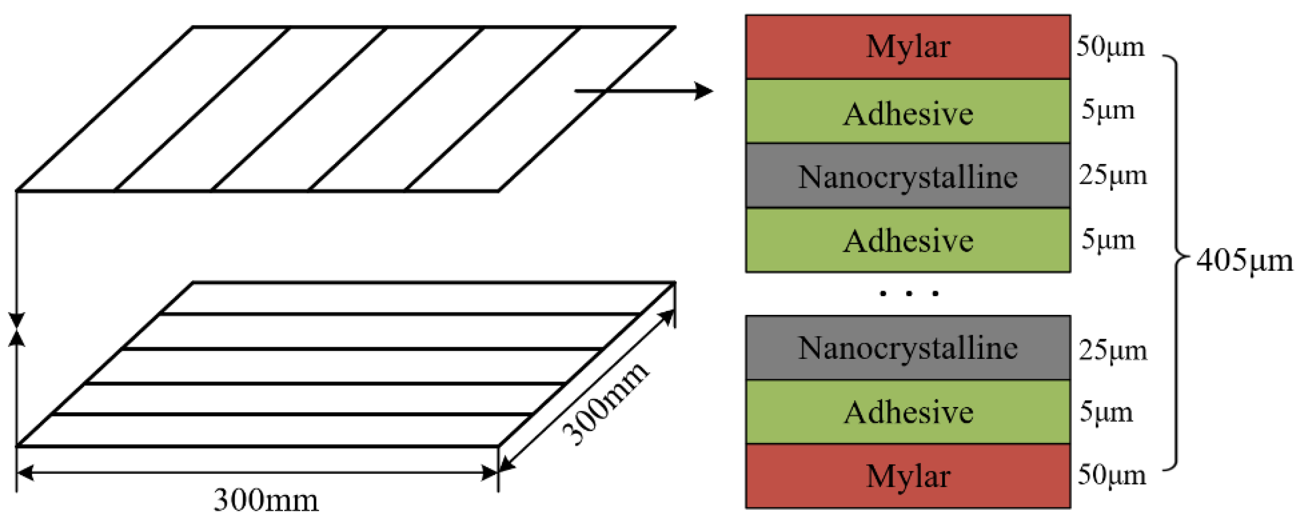
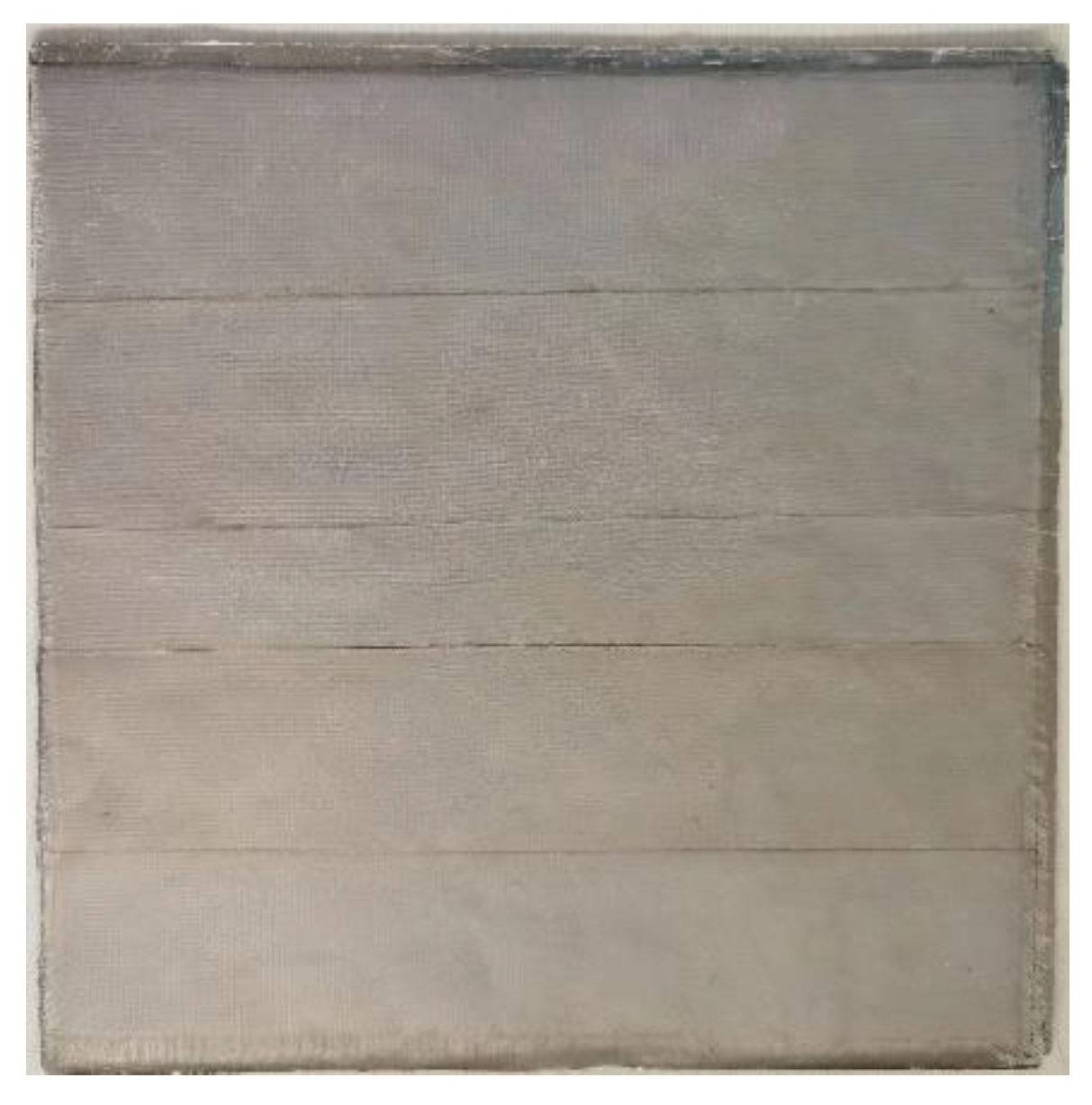
5.1. Composite Material Preparation

Experimental materials:
(1)
Quartz fiber was provided by Henan Shenjiu Tianhang New Material Co., Ltd. (Zhengzhou, China) under model number SJ108, with a plain-weave structure and a thickness of 0.1 mm;
(2)
Nanocrystals were provided by Hitachi Metals, Tokyo, Japan, in the form of iron-based nanocrystals (FeCuNbSiB) with a permeability of 157,000 and a saturation flux density of 1.24 T;
(3)
Epoxy resin was provided by Tianjin Jingdong Chemical Composites Co., Ltd. (Tianjin, China) under model number 86#; the curing agent was methyl tetrahydrophthalic anhydride, which was provided by Wenzhou Qingming Chemical Co., Ltd. (Wenzhou, China).
Production process:
Five pieces of 300 mm × 60 mm nanocrystals were laid on the bottom of a 300 mm × 300 mm mold in the 0° direction, and a new layer of nanocrystals was tiled above the 0° nanocrystals in the 90° direction. The middle was evenly coated with epoxy resin. The tiling was repeated twice according to the 0°–90°-alternating layering method to form a four-layer nanocrystalline structure. Four layers of quartz fibers were laid on top of the nanocrystals, and each layer was also coated with epoxy resin. The mold was seal, a curing agent was added, and it was cured in a gradient-heating manner. The curing program was 110 °C for 2 h, 130 °C for 2 h, and 160 °C for 3 h. Finally, a quartz fiber and nanocrystal reinforced resin matrix composite material with a thickness of 2 mm was obtained, as shown in Figure 10.

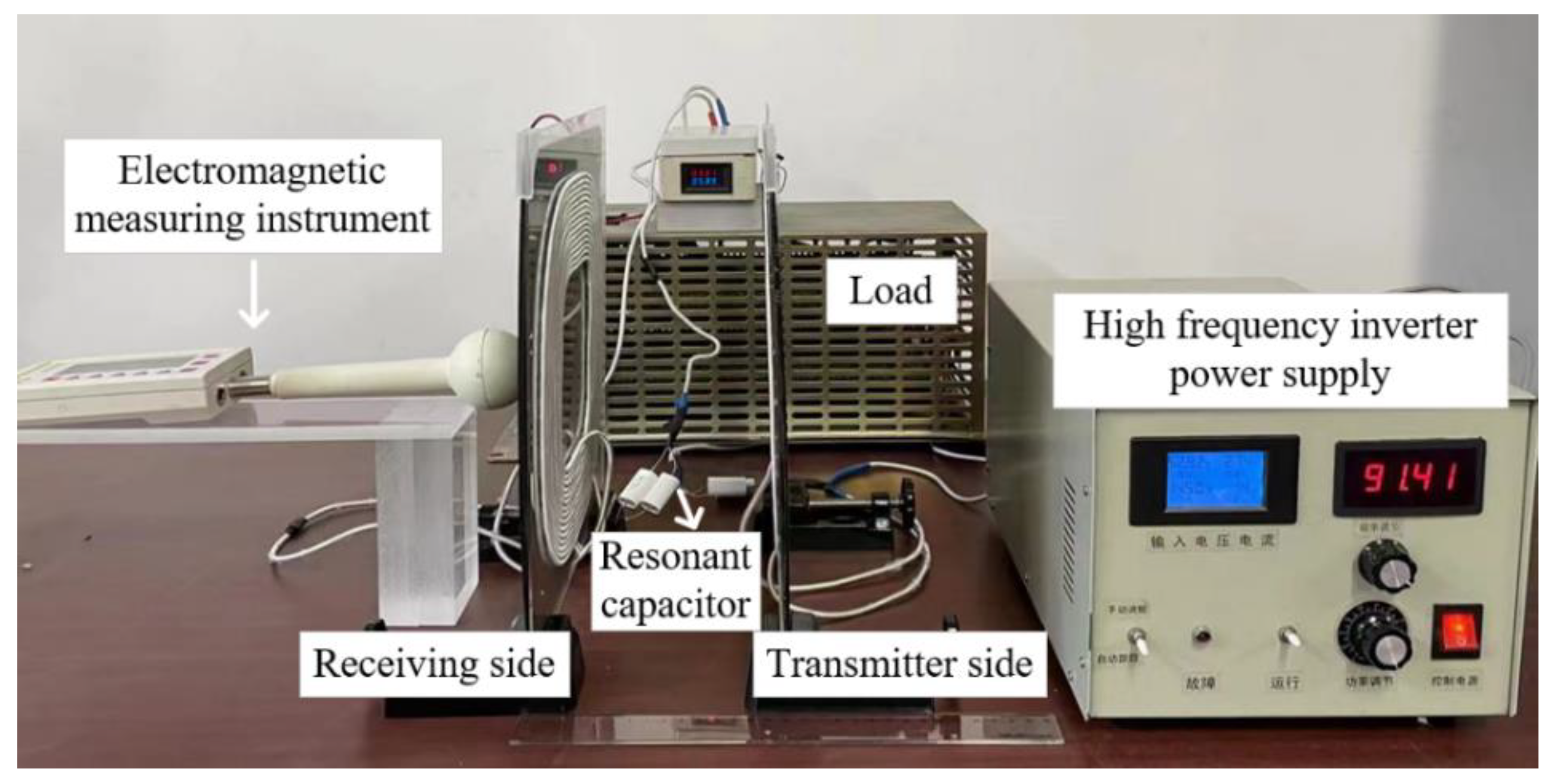
5.2. Experimental Platform Construction

In order to better verify the shielding effect of the new shielding mechanism, experimental verification was conducted. An experimental prototype of a WPT system was built, as shown in Figure 11. The power supply chosen for the experiment was a self-tracking, high-frequency inverter power supply with an internal frequency-tracking structure, which kept the system in resonance. The electromagnetic measuring instrument was a Maschek ESM-100H/E, which was used to measure the magnetic flux density at a certain position. The compensation capacitor of the system was a polypropylene film capacitor with a low loss factor and a high voltage rating.
In this paper, the structure in the simulation analysis was used as an example to produce a coupling mechanism with the same parameters as the simulation model. The distance of the air gap between the coils was 150 mm. The ferrite was PC95 Mn-Zn ferrite made by TDK, consisting of 36 sheets of 50 mm × 50 mm × 2 mm with a weight of 442.8 g. Compared with the ferrite, the weight of the composite was 322.1 g, which was 27.2% lower.

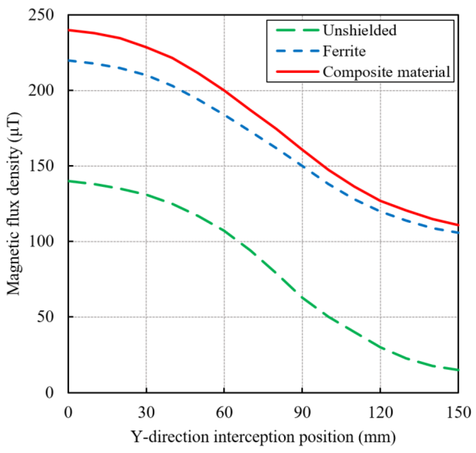
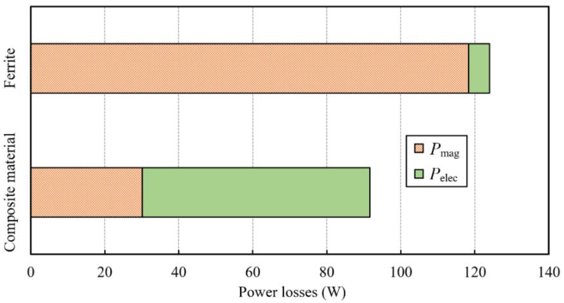
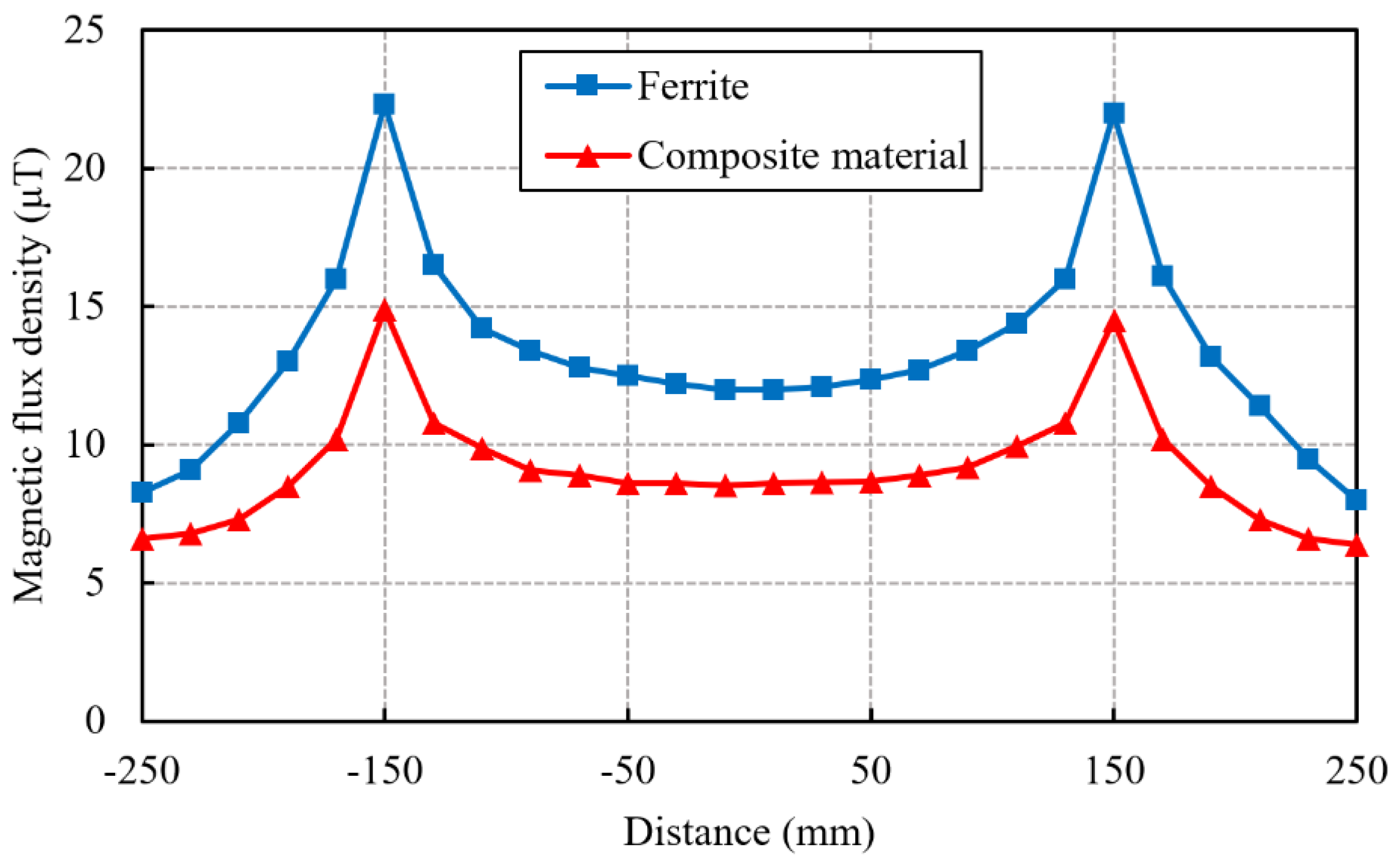
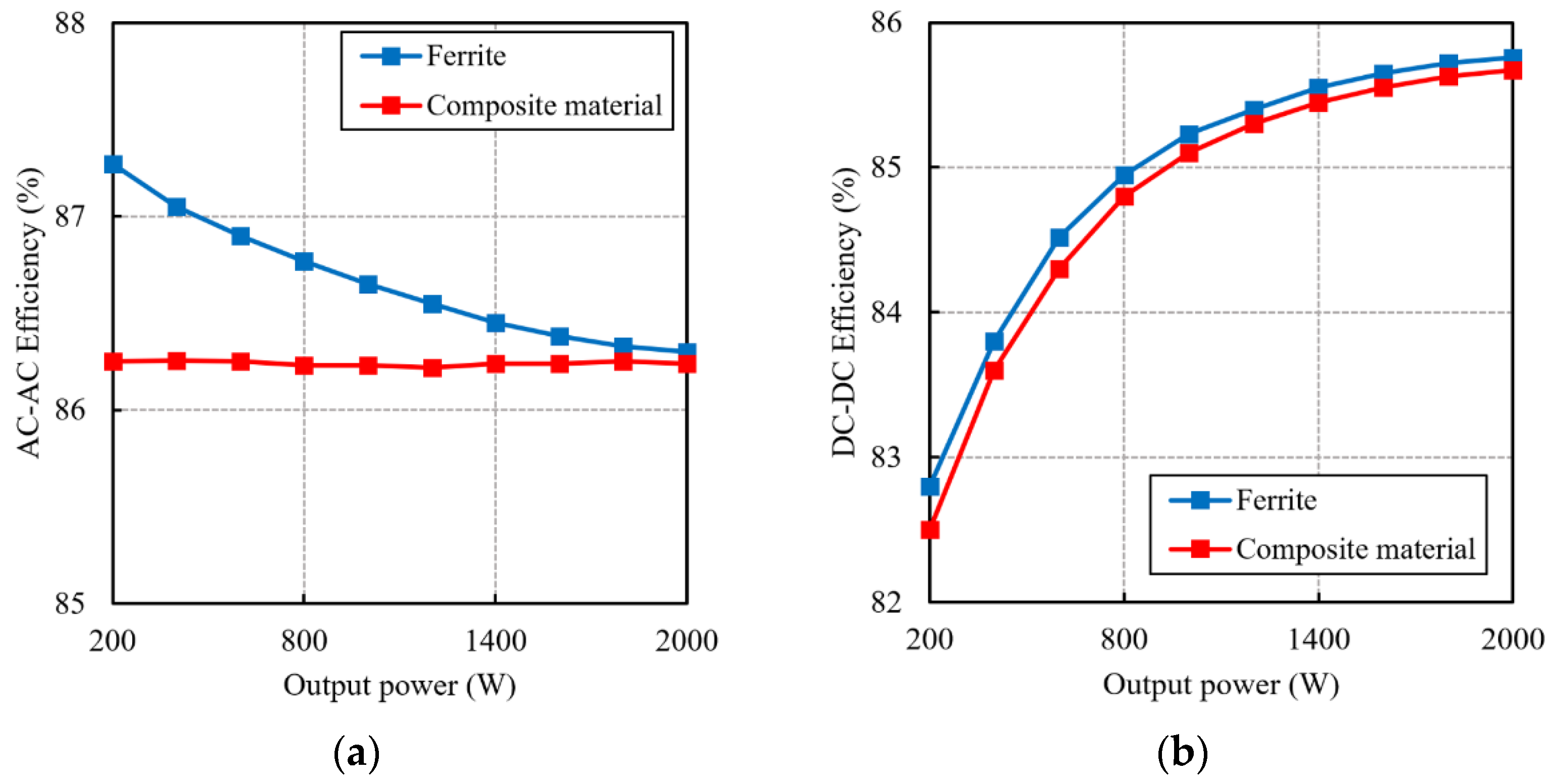
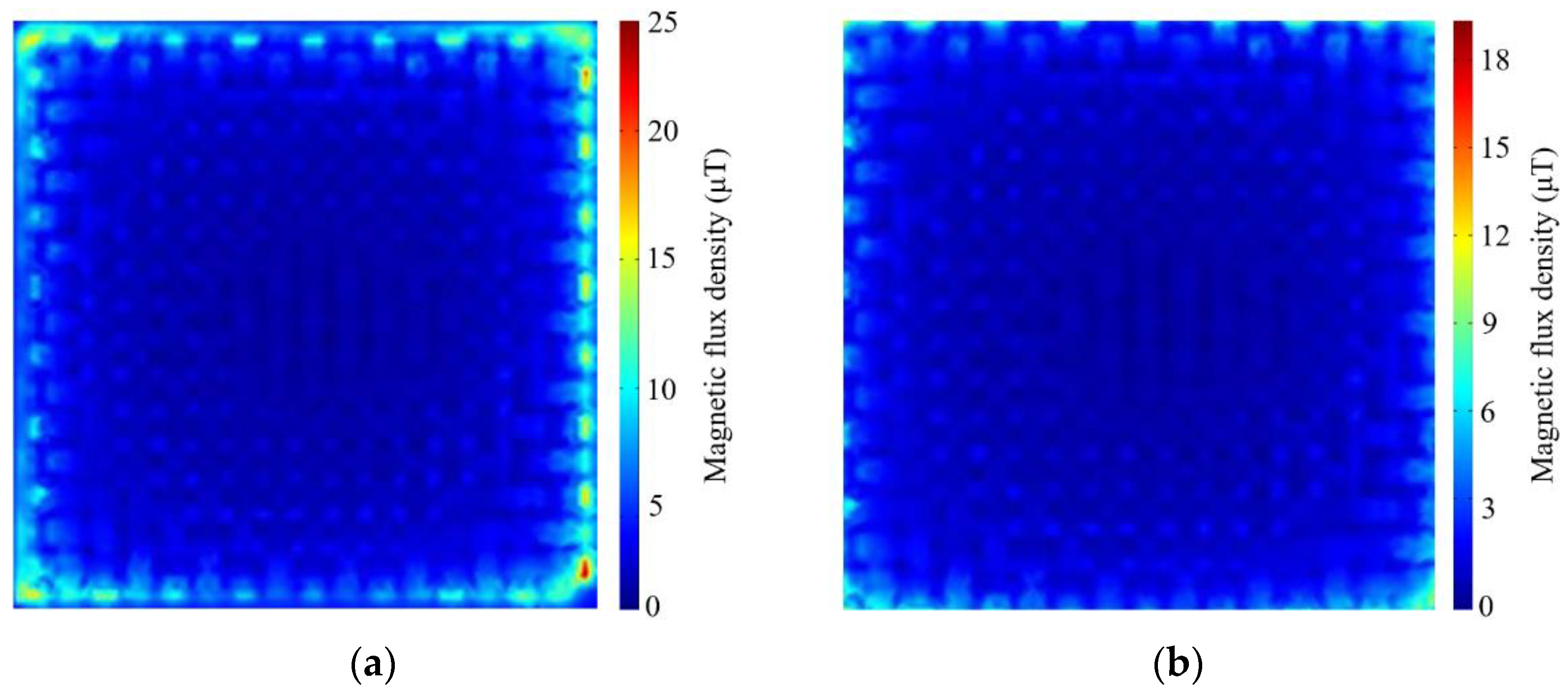
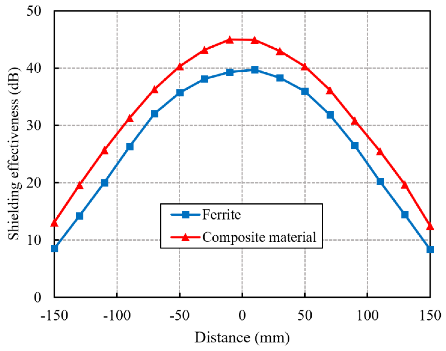
5.3. Experimental Results and Analysis

The inductance parameters of the coils were measured using an impedance analyzer, and the results are shown in Table 3. As can be seen, there was a difference between the simulated and experimental results that was due to the fact that the coil used in the simulation model was a densely wound coil with almost 0 turn spacing, while the coil could not be guaranteed to have 0 turn spacing in the actual winding process, resulting in a smaller inductance of the actual coil than the simulation model. Compared to ferrite, the self-inductance of the coil was about 3% higher when using the composite material, and similarly, the mutual inductance was 6.8% higher, resulting in a 4.3% increase in the coupling coefficient.
The center line (10 mm above the receiving side) was selected as the measurement line, and an electromagnetic measuring instrument was used to measure the magnetic flux density. The experimental results obtained are shown in Figure 12. Due to the edge effect, the maximum values of the magnetic flux density were 22.3 μT and 14.9 μT, and the minimum values were 12 μT and 8.6 μT for the ferrite and composite shielding structures, respectively. Compared to ferrite, the composite material reduced the magnetic flux density by 32.6% in the edge region of the shield and by 24.7% in the center region. Limiting the leakage of the magnetic field in space also reduced the influence of the edge effect.
Shielding effectiveness is usually used in practical applications to assess whether the structure and performance of a shielding is good. It is defined as the ratio of the magnetic field strength H0 at a point in space when no shielding is applied to the magnetic field strength H1 when shielding is applied, and can be expressed in decibels as:
S E ( dB ) = 20 lg H 0 H 1
Using the experimental data obtained before and after shielding, the shielding effectiveness at the measurement line was plotted, as shown in Figure 13. The shielding effectiveness of the two shielding structures at the shielding edge was different by 4.6 dB, or about 27.4%; the difference in the central area was 6.2 dB, or about 20.7%. The high magnetic permeability and the multilayer structure of the composite material played a good role in suppressing the leakage of the magnetic field and effectively protecting the electromagnetic safety in the nonworking area.
The transmission efficiency of the intercoil AC–AC was analyzed using a power analyzer, and the experimental results are shown in Figure 14a. For the coupling mechanism with the composite material, the efficiency stayed around 86.2% with the increase in the transferred power. However, the coupling mechanism with ferrite had an efficiency of 87.2% at low power and decreased with the increase in the transmission power. At a transmission power of 2 kW, the efficiency was about 86.3%. This was due to the fact that the hysteresis loss in ferrite material tends to increase exponentially with the increase in flux density, and therefore, the quality factor of the coil deteriorates at high-power transmission. The transmission efficiency of the system DC–DC was analyzed, and the results are shown in Figure 14b. The overall efficiency of the system could reach 85.7% for ferrite shielding and 85.6% for composite material shielding. The new magnetic shielding mechanism maintained the high transmission efficiency of the system, reduced the weight, and enhanced the mechanical properties of the shield.

6. Conclusions

To address problems of brittle ferrite and the high eddy current loss of nanocrystals, a new magnetic shielding mechanism was proposed in this paper: quartz fiber and nanocrystal reinforced resin matrix composite. By using epoxy resin and a staggered, laminated splicing process, the resistivity of the nanocrystal core was improved, and the eddy current loss was improved. In addition, a discrete geometric modeling method was proposed for quartz fibers to ensure the accuracy of the simulation.
The spatial magnetic fields of the transmitting and receiving sides were analyzed using finite element analysis software, and the results showed that the mutual inductance and coupling coefficients between the coils were improved compared with those of the ferrite after adding the composite material, while the flux density in the edge space was reduced by 7 μT and 6.2 μT, respectively, reducing the negative influence caused by the edge effect. In this paper, an experimental platform was built, and the spatial magnetic field distribution was measured; the actual situation of the magnetic field distribution was consistent with the simulation results. From the simulation and experimental results, it can be seen that the shielding effect of the composite material was better than that of ferrite, achieving a high transmission efficiency of 85.6%, which verified the effectiveness of the new magnetic shielding mechanism.

Author Contributions

Writing—original draft preparation, R.H. and F.L.; supervision, X.Z.; soft-ware, F.L.; writing—review and editing, X.P.; validation, Z.C. All authors have read and agreed to the published version of the manuscript.

Funding

This research was funded by the National Natural Science Foundation of China under Grant 52077153, the Tianjin Natural Science Foundation under Grant 20JCYBJC00190, and the Tianjin Research Innovation Project for Postgraduate Students under Grant 2020YJSS001.

Conflicts of Interest

The authors declare no conflict of interest.

References

  1. Liu, Y.; Wu, T.; Fu, M. Interleaved Capacitive Coupler for Wireless Power Transfer. IEEE Trans. Power Electron. 2021, 36, 13526–13535. [Google Scholar] [CrossRef]
  2. Zhang, Z.; Pang, H.; Georgiadis, A.; Cecati, C. Wireless Power Transfer—An Overview. IEEE Trans. Ind. Electron. 2019, 66, 1044–1058. [Google Scholar] [CrossRef]
  3. Sun, J.; Cho, J.; Huang, A.; Kim, H.; Fan, J. Accurate Rectifier Characterization and Improved Modeling of Constant Power Load Wireless Power Transfer Systems. IEEE Trans. Power Electron. 2020, 35, 7840–7852. [Google Scholar] [CrossRef]
  4. Jiang, Y.; Wang, L.; Wang, Y.; Liu, J.; Li, X.; Ning, G. Analysis, Design, and Implementation of Accurate ZVS Angle Control for EV Battery Charging in Wireless High-Power Transfer. IEEE Trans. Ind. Electron. 2019, 66, 4075–4085. [Google Scholar] [CrossRef]
  5. Zhang, H.; Gao, S.; Ngo, T.; Wu, W.; Guo, Y. Wireless Power Transfer Antenna Alignment Using Intermodulation for Two-Tone Powered Implantable Medical Devices. IEEE Trans. Microwave Theory Tech. 2019, 67, 1708–1716. [Google Scholar] [CrossRef]
  6. Van, S.; Ngo, H.; Cotton, S. Wireless Powered Wearables Using Distributed Massive MIMO. IEEE Trans. Commun. 2020, 68, 2156–2172. [Google Scholar] [CrossRef] [Green Version]
  7. Zhou, J.; Zhang, B.; Xiao, W.; Qiu, D.; Chen, Y. Nonlinear Parity-Time-Symmetric Model for Constant Efficiency Wireless Power Transfer: Application to a Drone-in-Flight Wireless Charging Platform. IEEE Trans. Ind. Electron. 2019, 66, 4097–4107. [Google Scholar] [CrossRef]
  8. Seo, D.; Lee, J. Frequency-Tuning Method Using the Reflection Coefficient in a Wireless Power Transfer System. IEEE Microwave Wireless Compon. Lett. 2017, 27, 959–961. [Google Scholar] [CrossRef]
  9. Sun, Y.; Liao, Z.; Ye, Z.; Tang, C.; Wang, P. Determining the Maximum Power Transfer Points for MC-WPT Systems with Arbitrary Number of Coils. IEEE Trans. Power Electron. 2018, 33, 9734–9743. [Google Scholar] [CrossRef]
  10. Kim, J.; Kim, J.; Kong, S.; Kim, H.; Suh, I.; Suh, N.; Cho, D.; Ahn, S. Coil Design and Shielding Methods for a Magnetic Resonant Wireless Power Transfer System. Proc. IEEE 2013, 101, 1332–1342. [Google Scholar] [CrossRef]
  11. Shah, I.; Yoo, H. Assessing Human Exposure with Medical Implants to Electromagnetic Fields from a Wireless Power Transmission System in an Electric Vehicle. IEEE Trans. Electromagn. Compat. 2020, 62, 338–345. [Google Scholar] [CrossRef]
  12. Park, H.; Kwon, J.; Kwak, S.; Ahn, S. Magnetic Shielding Analysis of a Ferrite Plate with a Periodic Metal Strip. IEEE Trans. Magn. 2015, 51, 1–8. [Google Scholar] [CrossRef]
  13. Feng, J.; Li, Q.; Lee, F. A Square-Shaped Omnidirectional Wireless Charing Bowl with a Double Layer Electromagnetic Shield for Portable Device Applications. In Proceedings of the 2019 IEEE Energy Conversion Congress and Exposition (ECCE), Baltimore, MD, USA, 29 September–3 October 2019; pp. 4961–4966. [Google Scholar]
  14. Bima, M.; Bhattacharya, I.; Neste, C. Experimental Evaluation of Layered DD Coil Structure in a Wireless Power Transfer System. IEEE Trans. Electromagn. Compat. 2020, 62, 1477–1484. [Google Scholar] [CrossRef]
  15. Peng, W.; Chen, Z. Enhanced Planar Wireless Power Transfer Systems with Ferrite Material. In Proceedings of the 2018 IEEE Wireless Power Transfer Conference (WPTC), Montreal, QC, Canada, 3–7 June 2018; pp. 1–4. [Google Scholar]
  16. Strauch, L.; Pavlin, M.; Bregar, V. Optimization, Design, and Modeling of Ferrite Core Geometry for Inductive Wireless Power Transfer. Int. J. Appl. Electromagn. Mech. 2015, 49, 145–155. [Google Scholar] [CrossRef] [Green Version]
  17. Castelli-Dezza, F.; Mauri, M.; Dolara, A.; Leva, S.; Longo, M. Power Pad Design and Optimization for Contactless Electric Vehicle Battery Charging System. In Proceedings of the 2017 IEEE International Conference on Environment and Electrical Engineering and 2017 IEEE Industrial and Commercial Power Systems Europe (EEEIC/I&CPS Europe), Milan, Italy, 6–9 June 2017; pp. 1–6. [Google Scholar]
  18. Mohammad, M.; Choi, S.; Islam, Z.; Kwak, S.; Baek, J. Core Design and Optimization for Better Misalignment Tolerance and Higher Range of Wireless Charging of PHEV. IEEE Trans. Transp. Electrif. 2017, 3, 445–453. [Google Scholar] [CrossRef]
  19. Corti, F.; Grasso, F.; Paolucci, L.; Pugi, L.; Luchetti, L. Circular Coil for EV Wireless Charging Design and Optimization Considering Ferrite Saturation. In Proceedings of the 2019 IEEE 5th International forum on Research and Technology for Society and Industry (RTSI), Florence, Italy, 9–12 September 2019; pp. 279–284. [Google Scholar]
  20. Choi, B.; Kim, Y. New Structure Design of Ferrite Cores for Wireless Electric Vehicle Charging by Machine Learning. IEEE Trans. Ind. Electron. 2021, 68, 12162–12172. [Google Scholar] [CrossRef]
  21. Seo, S.; Jo, H.; Bien, F. Free Arrangement Wireless Power Transfer System with a Ferrite Transmission Medium and Geometry-Based Performance Improvement. IEEE Trans. Power Electron. 2020, 35, 4518–4532. [Google Scholar] [CrossRef]
  22. Pearce, M.; Covic, G.; Boys, J. Reduced Ferrite Double D Pad for Roadway IPT Applications. IEEE Trans. Power Electron. 2021, 36, 5055–5068. [Google Scholar] [CrossRef]
  23. Delgado, A.; Schoenberger, D.; Oliver, J.; Alou, P.; Cobos, J. Design Guidelines of Inductive Coils Using a Polymer Bonded Magnetic Composite for Inductive Power Transfer Systems in Electric Vehicles. IEEE Trans. Power Electron. 2020, 35, 7884–7893. [Google Scholar] [CrossRef]
  24. Xiong, M.; Wei, X.; Huang, Y.; Luo, Z.; Dai, H. Research on Novel Flexible High-Saturation Nanocrystalline Cores for Wireless Charging Systems of Electric Vehicles. IEEE Trans. Ind. Electron. 2021, 68, 8310–8320. [Google Scholar] [CrossRef]
  25. Gaona, D.; Jiang, C.; Long, T. Highly Efficient 11.1-kW Wireless Power Transfer Utilizing Nanocrystalline Ribbon Cores. IEEE Trans. Power Electron. 2021, 36, 9955–9969. [Google Scholar] [CrossRef]
  26. Wang, Y.; Calderon-Lopez, G.; Forsyth, A. High-Frequency Gap Losses in Nanocrystalline Cores. IEEE Trans. Power Electron. 2017, 32, 4683–4690. [Google Scholar] [CrossRef]
  27. Li, Y.; Zhao, J.; Yang, Q.; Liu, L.; Ma, J.; Zhang, X. A Novel Coil with High Misalignment Tolerance for Wireless Power Transfer. IEEE Trans. Magn. 2019, 55, 1–4. [Google Scholar] [CrossRef]
  28. Holloway, C.; Sarto, M.; Johansson, M. Analyzing Carbon-Fiber Composite Materials with Equivalent-Layer Models. IEEE Trans. Electromagn. Compat. 2005, 47, 833–844. [Google Scholar] [CrossRef]
  29. Campi, T.; Cruciani, S.; Santis, V.; Maradei, F.; Feliziani, M. Numerical Calculation of the Near Field Shielding for Carbon Fiber Reinforced Polymer (CFRP) Panels at Wireless Power Transfer Automotive Frequencies. In Proceedings of the 2018 IEEE Symposium on Electromagnetic Compatibility, Signal Integrity and Power Integrity (EMC, SI & PI), Long Beach, CA, USA, 30 July–3 August 2018; pp. 444–447. [Google Scholar]
Figure 1. Equivalent circuit diagram of S/S-compensated WPT system.
Electronics 11 02187 g001
Figure 2. Nanocrystalline staggered lamination splicing process.
Electronics 11 02187 g002
Figure 3. Coupling mechanism of WPT.
Electronics 11 02187 g003
Figure 4. Quartz fiber discretization simulation model.
Electronics 11 02187 g004
Figure 5. Simulation results of magnetic field distribution in x–z plane of ferrite shield: (a) transmitting side and (b) receiving side.
Electronics 11 02187 g005
Figure 6. Simulation results of magnetic field distribution in x–z plane of composite material shielding: (a) transmitting side and (b) receiving side.
Electronics 11 02187 g006
Figure 7. Simulation results of spatial magnetic field distribution in x–y plane: (a) ferrite shield and (b) composite material shield.
Electronics 11 02187 g007
Figure 8. The magnetic flux density distribution on the y-axis direction.
Electronics 11 02187 g008
Figure 9. Comparison of power losses of different shields at 2 KW.
Electronics 11 02187 g009
Figure 10. Quartz fiber and nanocrystalline reinforced resin matrix composite material.
Electronics 11 02187 g010
Figure 11. Experiment platform.
Electronics 11 02187 g011
Figure 12. Magnetic flux density distribution at the measurement line.
Electronics 11 02187 g012
Figure 13. Shielding effectiveness at the measurement line.
Electronics 11 02187 g013
Figure 14. Efficiency measurements: (a) inter-coil efficiency and (b) overall efficiency of the system.
Electronics 11 02187 g014
Table 1. Main parameters of the coupling mechanism simulation model.
ParameterSymbolValue
Coil inner diameterRci130 mm
Coil outer diameterRco260 mm
Wire radiusr2.5 mm
Transmission distanceD150 mm
Coil turnsN15
Magnetic shield thicknessT2 mm
Table 2. Coil inductance simulation results.
Shield TypeUnshieldedFerriteComposite Material
Self-inductance (μH)62.31106.23109.35
Mutual inductance (μH)7.5419.5120.78
Coupling coefficient (k)0.1210.1830.19
Table 3. Coil inductance measurement results.
Shield TypeUnshieldedFerriteComposite Material
Self-inductance (μH)60.92105.26108.34
Mutual inductance (μH)7.2518.9520.36
Coupling coefficient (k)0.1190.180.188
Publisher’s Note: MDPI stays neutral with regard to jurisdictional claims in published maps and institutional affiliations.

