
A Fault Clearance and Restoration Approach for MMC-Based MTDC Grid

 , , and
Abstract
:1. Introduction
2. Modeling and Control of the MTDC System
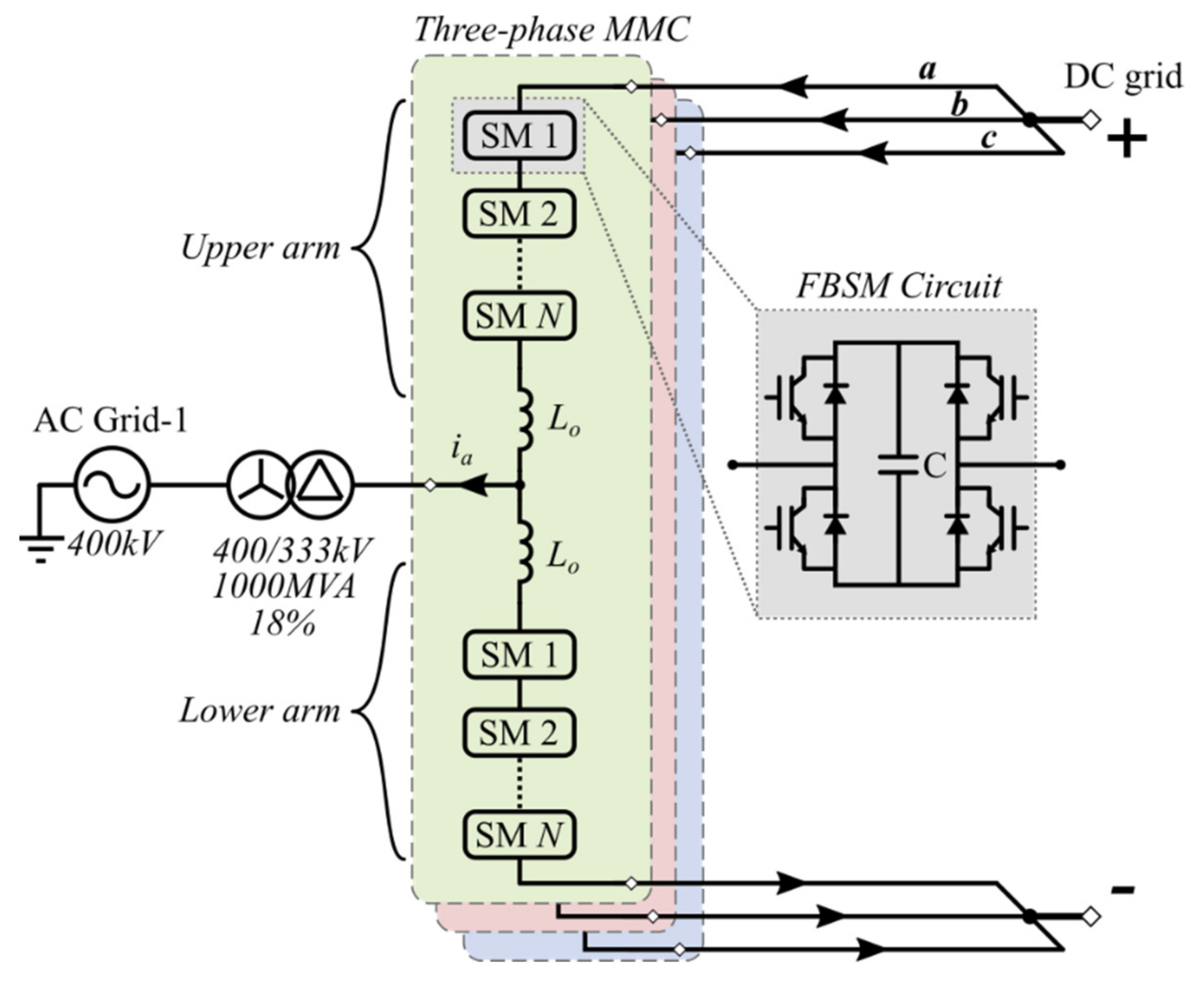
2.1. MMC System
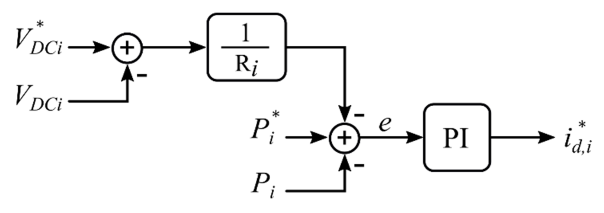
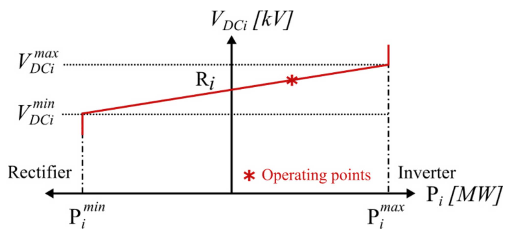
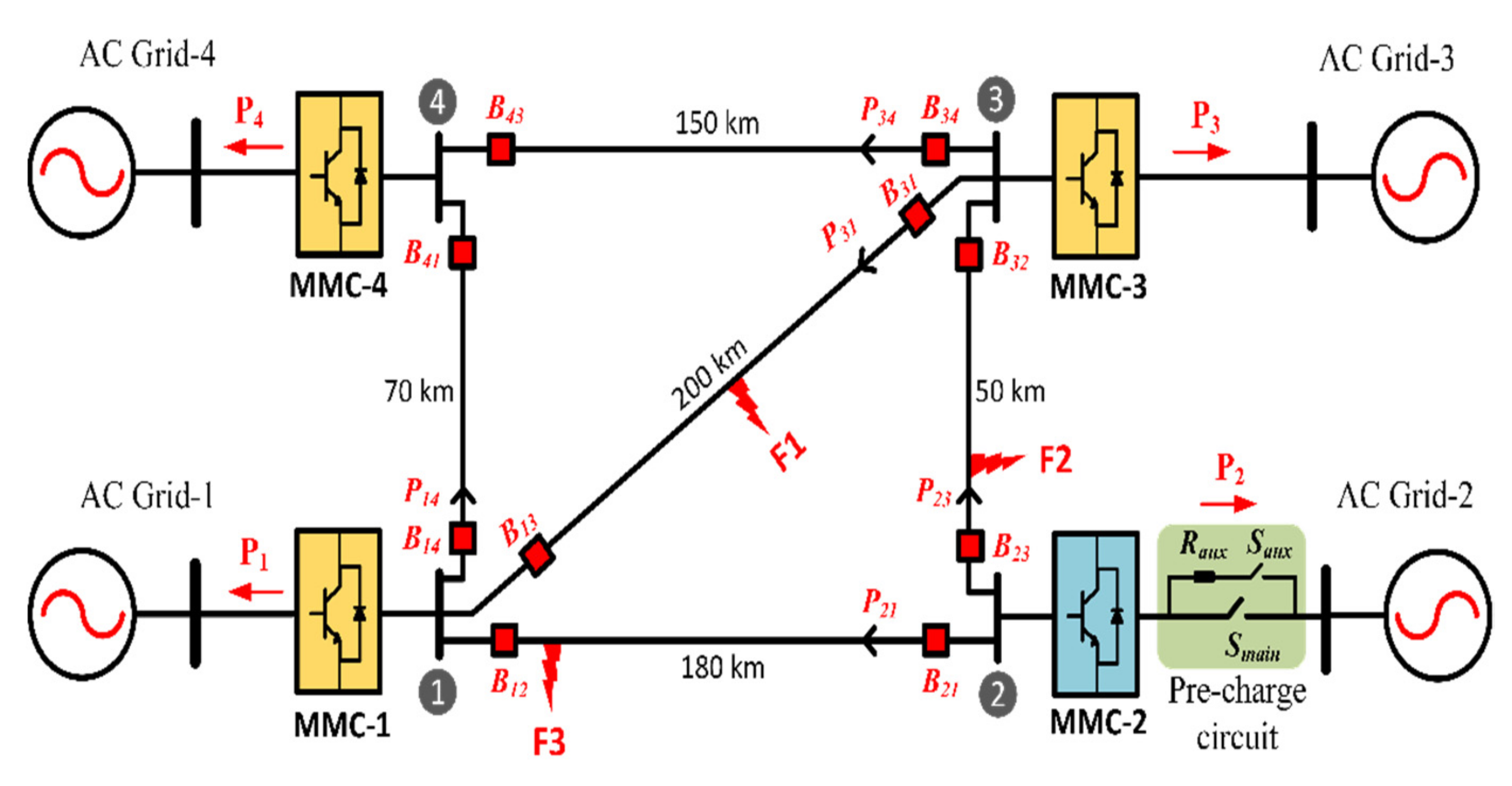
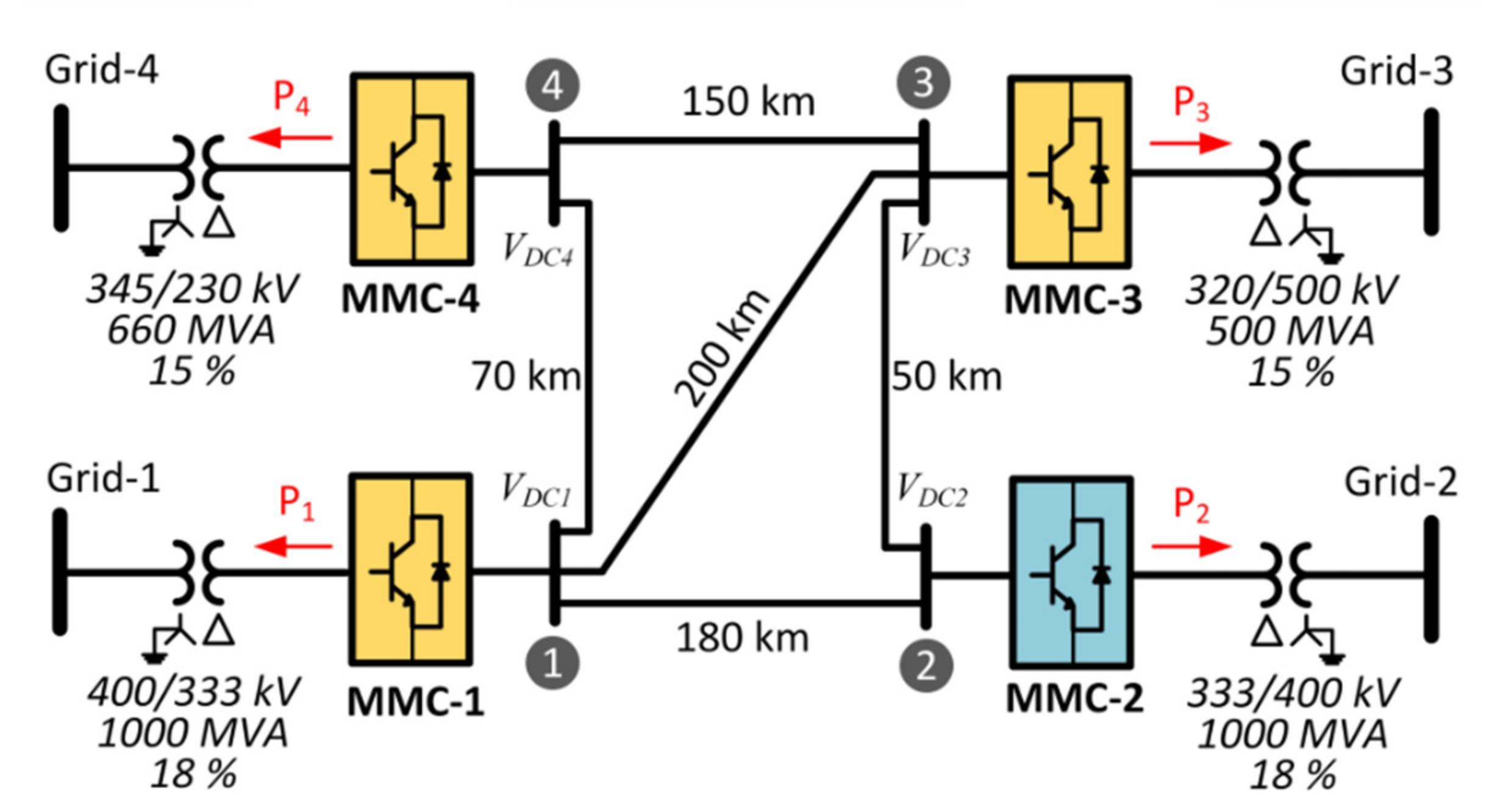
2.2. MTDC Grid
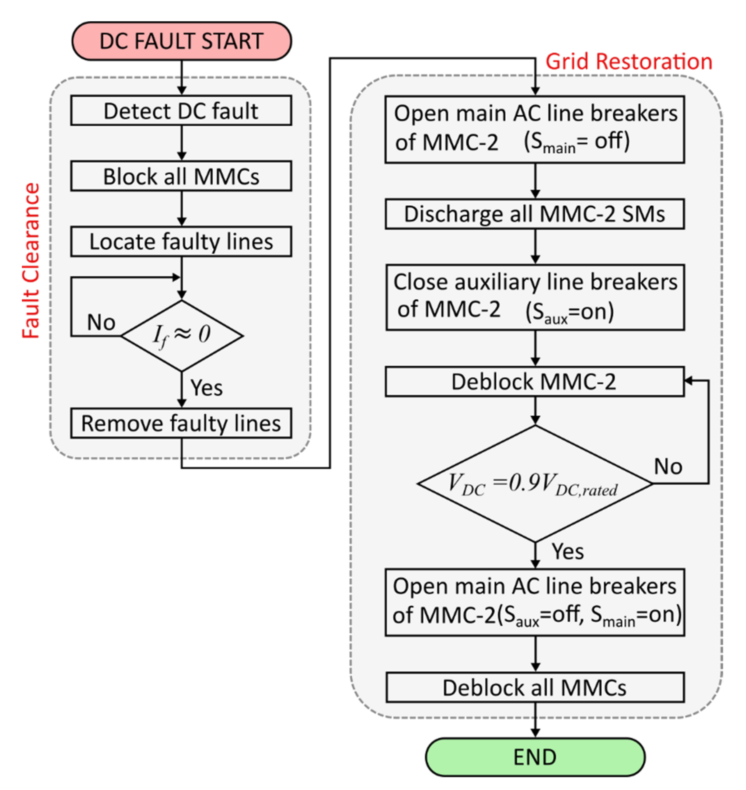
3. Proposed DC Fault Clearance and Restoration Scheme
3.1. DC Fault Detection
3.2. DC Fault Clearance and Isolation
3.3. MTDC Grid Restoration Scheme
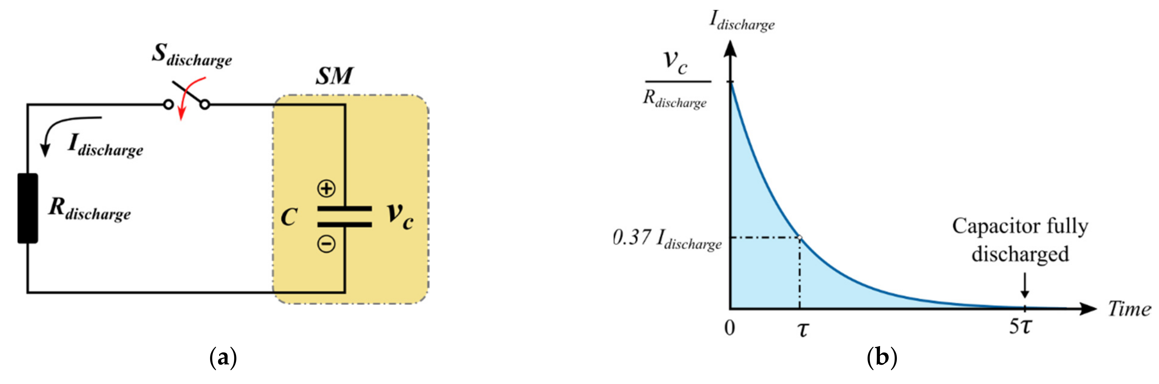
3.3.1. Discharging System
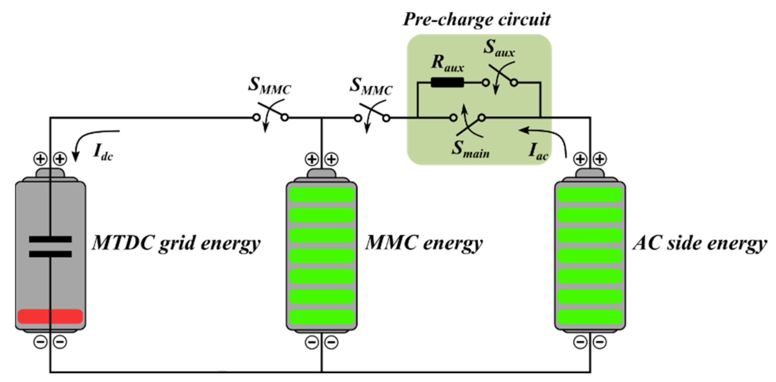
3.3.2. Pre-Charge Circuit
4. RTDS Results
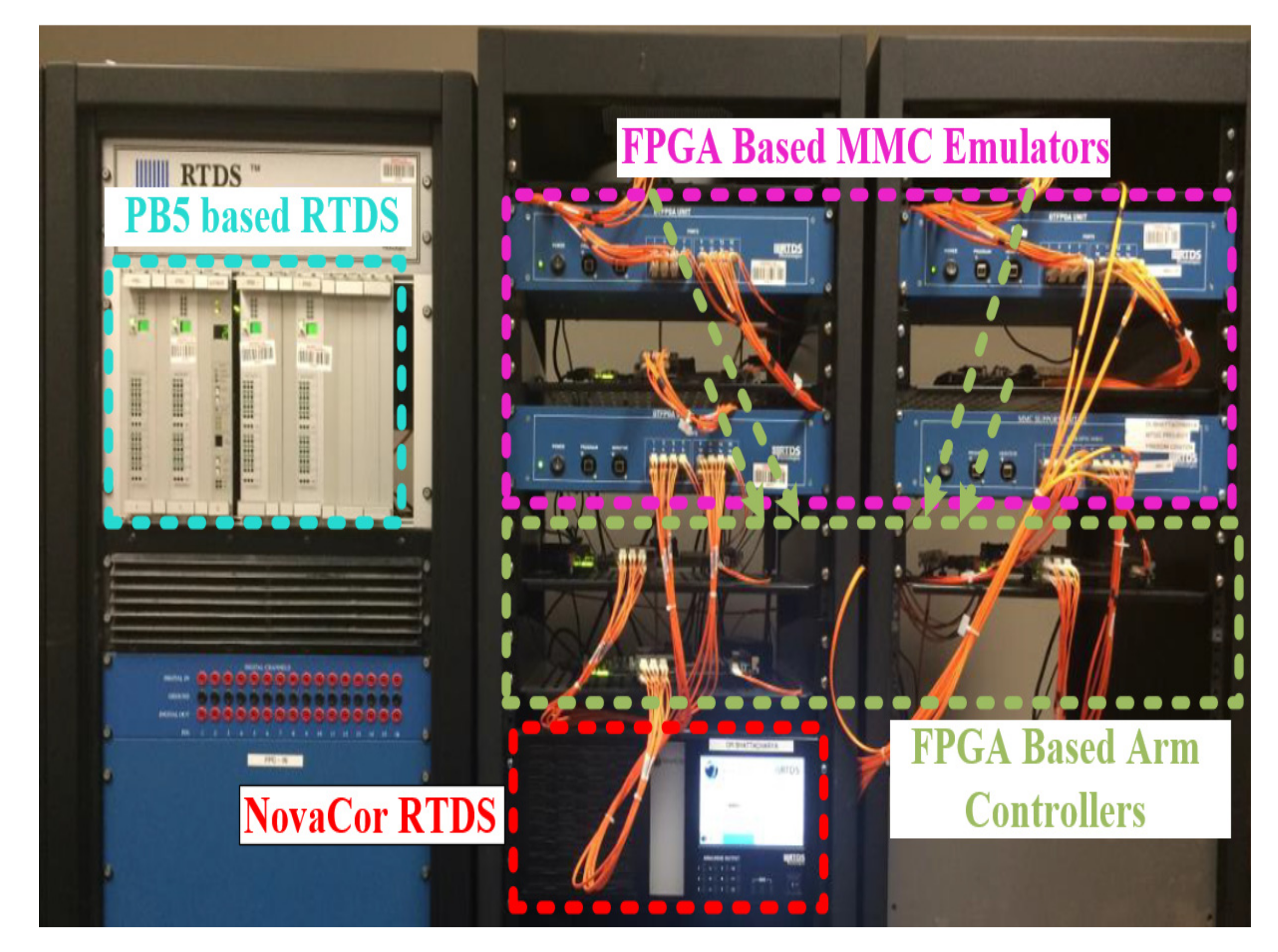
4.1. CHIL Implementation
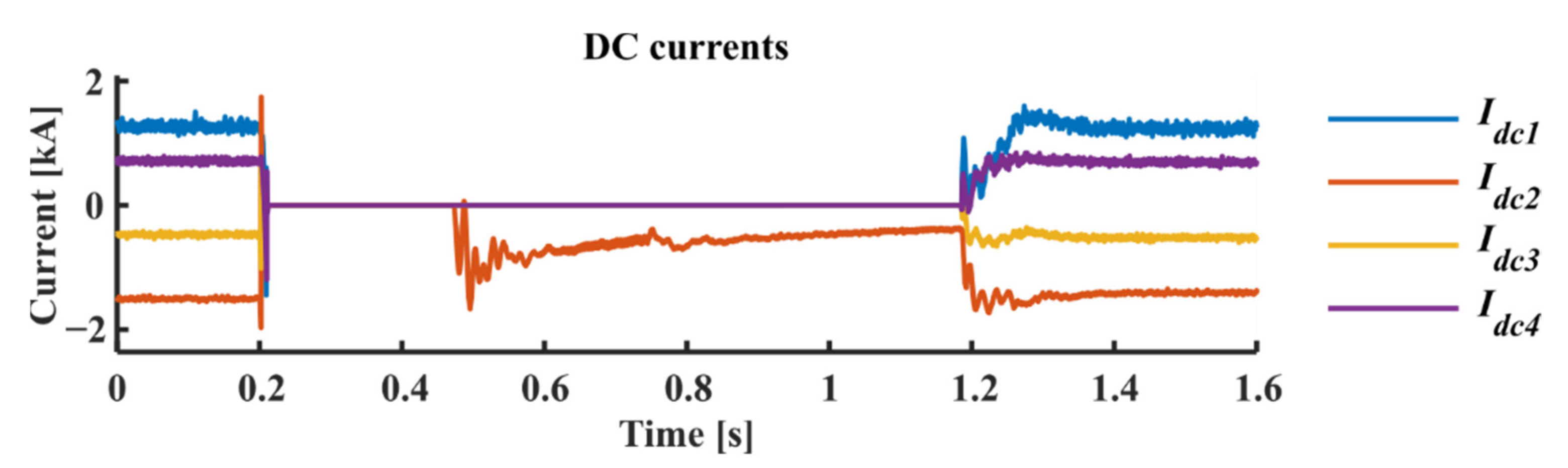
4.2. Verification of the DC Fault Clearance and Grid Restoration Scheme
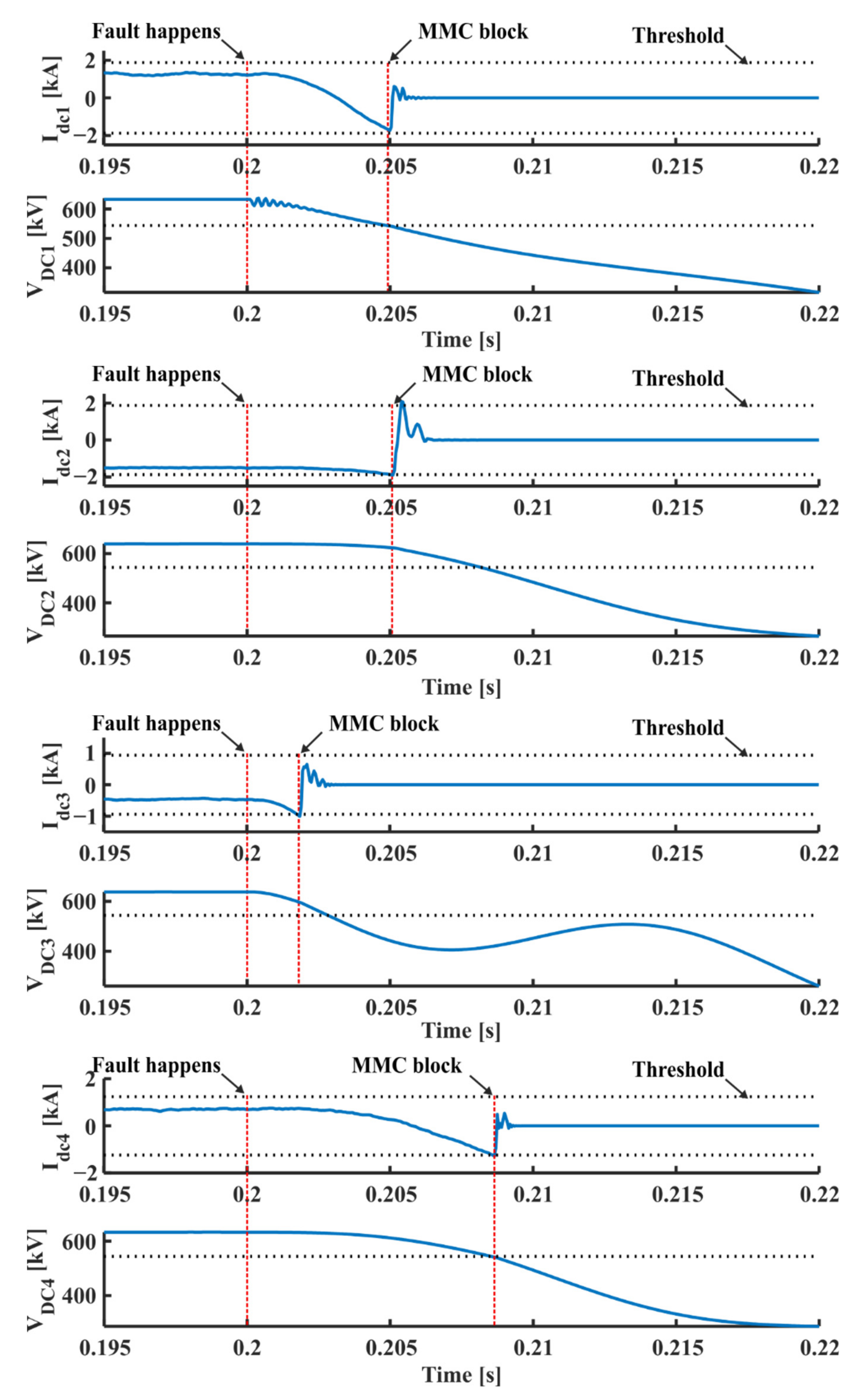
4.2.1. DC Fault at the F1 Location
4.2.2. DC Fault at the F2 Location
4.2.3. DC Fault at the F3 Location
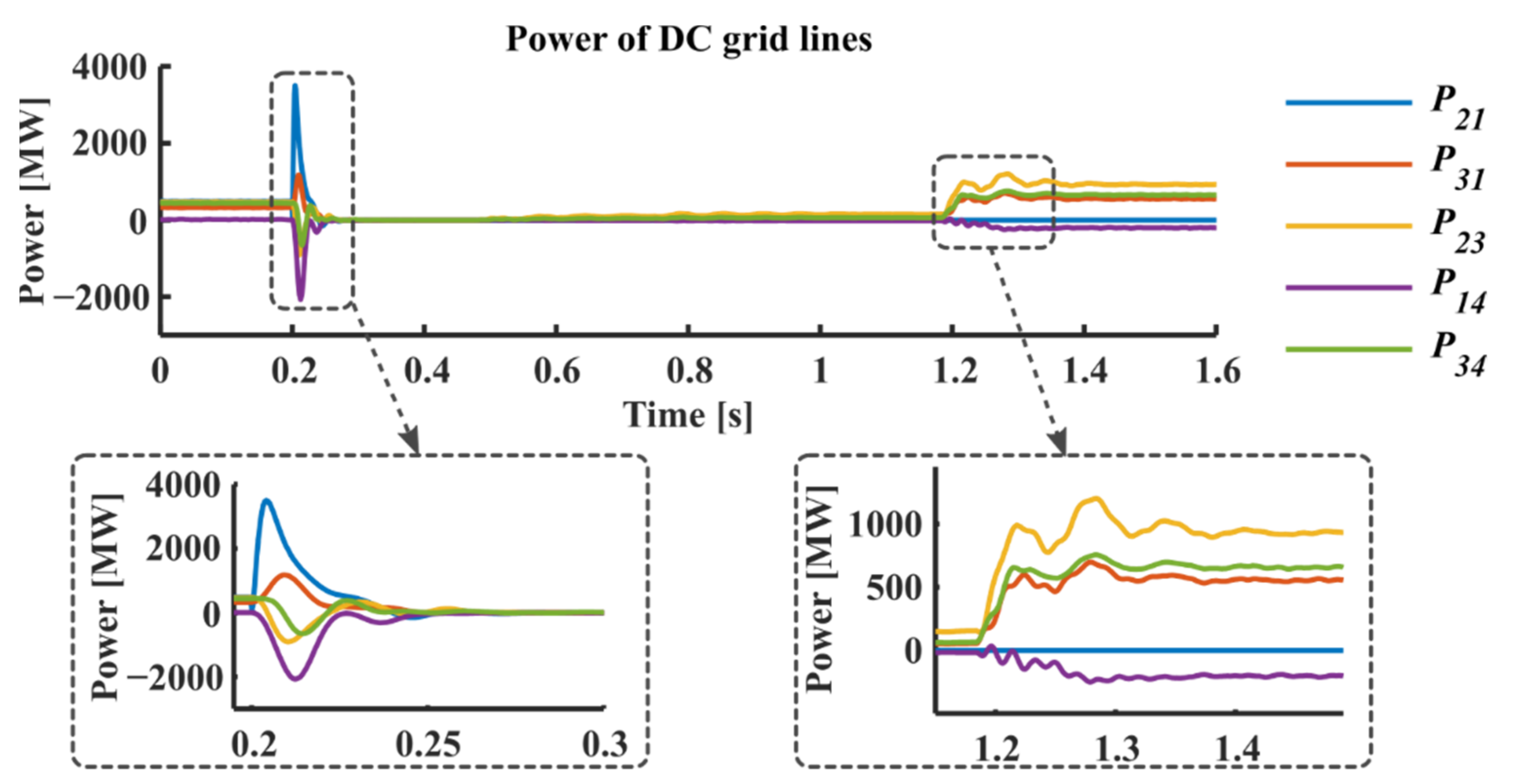
4.3. Power Flow Assessment of the MTDC Grid under Different Disconnected DC Lines
5. Conclusions
Author Contributions
Funding
Acknowledgments
Conflicts of Interest
Abbreviations
| MTDC | Multiterminal High Voltage DC |
| P2P | Pole-to-Pole |
| CHIL | Control-Hardware-in-Loop |
| RTDS | Real-Time Digital Simulator |
| CO2 | Carbon Dioxide |
| HVDC | High Voltage Direct Current |
| HVAC | High Voltage Alternating Current |
| ROW | Right-of-Ways |
| VSC | Voltage Source-based Converter |
| MMC | Modular Multilevel Converter |
| ACCB | AC Circuit Breaker |
| SCR | Short-Circuit Ratio |
| FBSM | Full Bridge Submodule |
| CCSC | Circulating Current Suppression Control |
| NLM | Nearest Level Modulation |
References
- Yang, R.; Shi, G.; Cai, X.; Zhang, C.; Li, G.; Liang, J. Autonomous Synchronizing and Frequency Response Control of Multi-terminal DC Systems with Wind Farm Integration. IEEE Trans. Sustain. Energy 2020, 11, 2504–2514. [Google Scholar] [CrossRef] [Green Version]
- Li, J.; Li, Y.; Xiong, L.; Jia, K.; Song, G. DC Fault Analysis and Transient Average Current Based Fault Detection for Radial MTDC System. IEEE Trans. Power Deliv. 2019, 35, 1310–1320. [Google Scholar] [CrossRef]
- Shinoda, K.; Benchaib, A.; Dai, J.; Guillaud, X. Over- and Under-Voltage Containment Reserves for Droop-Based Primary Voltage Control of MTDC Grids. IEEE Trans. Power Deliv. 2021, 37, 125–135. [Google Scholar] [CrossRef]
- Isik, S.; Nath, H.; Alharbi, M.; Bhattacharya, S. Dynamic Modelling and Control of Multi-Terminal DC Systems Considering AC Network Dynamics. In Proceedings of the 2020 IEEE Power & Energy Society General Meeting (PESGM), Montreal, QC, Canada, 2–6 August 2020; pp. 1–5. [Google Scholar] [CrossRef]
- Qiang, G.; Xi, Y.; Ye, L. Circulating Current Suppressing and AC Faults Ride-Through Capability Analysis of Zhoushan MMC-MTDC System. In Proceedings of the 2018 2nd IEEE Conference on Energy Internet and Energy System Integration (EI2), Beijing, China, 20–22 October 2018; pp. 1–6. [Google Scholar] [CrossRef]
- Jiang, B.; Gong, Y.; Li, Y. Fault Detection and Location of IGBT Short-Circuit Failure in Modular Multilevel Converters. Energies 2018, 11, 1492. [Google Scholar] [CrossRef] [Green Version]
- CIGRE B4.52 Working Group. HVDC Grid Feasibility Study; Technical Report 533; CIGRE: Paris, France, 2013. [Google Scholar]
- Tang, G.; He, Z.; Pang, H.; Huang, X.; Zhang, X.-P. Basic topology and key devices of the five-terminal DC grid. CSEE J. Power Energy Syst. 2015, 1, 22–35. [Google Scholar] [CrossRef]
- Tang, L.; Ooi, B.-T. Locating and Isolating DC Faults in Multi-Terminal DC Systems. IEEE Trans. Power Deliv. 2007, 22, 1877–1884. [Google Scholar] [CrossRef]
- Ludin, G.; Amin, M.; Matayoshi, H.; Rangarajan, S.; Hemeida, A.; Takahashi, H.; Senjyu, T. Solid-State DC Circuit Breakers and Their Comparison in Modular Multilevel Converter Based-HVDC Transmission System. Electronics 2021, 10, 1204. [Google Scholar] [CrossRef]
- Feng, L.; Gou, R.; Yang, X.; Zhuo, F.; Wang, F. Research on Large Current Interruption of Solid-State Switch for a Hybrid DCCB. In Proceedings of the 2019 IEEE Applied Power Electronics Conference and Exposition (APEC), Anaheim, CA, USA, 17–21 March 2019; pp. 2362–2365. [Google Scholar] [CrossRef]
- Li, B.; He, J.; Li, Y.; Wen, W. A Novel DCCB Reclosing Strategy for the Flexible HVDC Grid. IEEE Trans. Power Deliv. 2019, 35, 244–257. [Google Scholar] [CrossRef]
- Schultz, T.; Lenz, V.; Franck, C.M. Circuit Breakers for Fault Current Interruption in HVDC Grids. In Proceedings of the VDE High Voltage Technology 2016, ETG-Symposium, Berlin, Germany, 14–16 November 2016. [Google Scholar]
- Wang, Y.; Marquardt, R. A fast switching, scalable DC-Breaker for meshed HVDCSuperGrids. In Proceedings of the PCIM Europe 2014, International Exhibition and Conference for Power Electronics, Intelligent Motion, Renewable Energy and Energy Management, Nuremberg, Germany, 20–22 May 2014; Available online: https://ieeexplore.ieee.org/document/6841225 (accessed on 28 September 2021).
- Li, H.; Xiang, B.; Wang, X.; Li, S.; Liu, S.; Geng, Y.; Liu, Z.; Wang, J. Flexible Fault Current Adaptation Features of a Novel DC Circuit Breaker Assisted by Superconducting Fault Current Limiters. IEEE Trans. Power Deliv. 2021, 37, 2348–2358. [Google Scholar] [CrossRef]
- Luo, Y.; He, J.; Luo, G.; Zhang, Y. Fast DC fault location and isolation strategy for the flexible multi-terminal DC system. J. Eng. 2018, 2018, 908–912. [Google Scholar] [CrossRef]
- Li, R.; Xu, L.; Yao, L. DC Fault Detection and Location in Meshed Multiterminal HVDC Systems Based on DC Reactor Voltage Change Rate. IEEE Trans. Power Deliv. 2016, 32, 1516–1526. [Google Scholar] [CrossRef] [Green Version]
- Li, C.; Gole, A.M.; Zhao, C. A Fast DC Fault Detection Method Using DC Reactor Voltages in HVdc Grids. IEEE Trans. Power Deliv. 2018, 33, 2254–2264. [Google Scholar] [CrossRef]
- Tu, Q.; Xu, Z.; Xu, L. Reduced Switching-Frequency Modulation and Circulating Current Suppression for Modular Multilevel Converters. IEEE Trans. Power Deliv. 2011, 26, 2009–2017. [Google Scholar]
- Alharbi, M.; Isik, S.; Bhattacharya, S. A Novel Submodule Level Fault-Tolerant Approach for MMC With Integrated Scale-Up Architecture. IEEE J. Emerg. Sel. Top. Ind. Electron. 2021, 2, 343–352. [Google Scholar] [CrossRef]
- Nasir, M.; Khan, H.A.; Hussain, A.; Mateen, L.; Zaffar, N.A. Solar PV-Based Scalable DC Microgrid for Rural Electrification in Developing Regions. IEEE Trans. Sustain. Energy 2018, 9, 390–399. [Google Scholar] [CrossRef]
- Liu, J.; Tai, N.; Fan, C. Transient-Voltage-Based Protection Scheme for DC Line Faults in the Multiterminal VSC-HVDC System. IEEE Trans. Power Deliv. 2016, 32, 1483–1494. [Google Scholar] [CrossRef]
- Zhang, Y.; Ravishankar, J.; Fletcher, J. Power flow and transmission loss analysis of modular multi-level converter based multi-terminal high-voltage DC systems. IET Renew. Power Gener. 2016, 10, 767–775. [Google Scholar] [CrossRef]
- Dantas, R.; Liang, J.; Ugalde-Loo, C.E.; Adamczyk, A.; Barker, C.; Whitehouse, R. Progressive Fault Isolation and Grid Restoration Strategy for MTDC Networks. IEEE Trans. Power Deliv. 2017, 33, 909–918. [Google Scholar] [CrossRef] [Green Version]
- Wang, S.; Li, C.; Adeuyi, O.D.; Li, G.; Ugalde-Loo, C.E.; Liang, J. Coordination of MMCs With Hybrid DC Circuit Breakers for HVDC Grid Protection. IEEE Trans. Power Deliv. 2019, 34, 11–22. [Google Scholar] [CrossRef] [Green Version]
- Li, Y.; Gong, Y.; Jiang, B. A novel traveling-wave-based directional protection scheme for MTDC grid with inductive DC terminal. Electr. Power Syst. Res. 2017, 157, 83–92. [Google Scholar] [CrossRef]
- Tzelepis, D.; Dyśko, A.; Fusiek, G.; Niewczas, P.; Mirsaeidi, S.; Booth, C.; Dong, X. Advanced fault location in MTDC networks utilising optically-multiplexed current measurements and machine learning approach. Int. J. Electr. Power Energy Syst. 2018, 97, 319–333. [Google Scholar] [CrossRef] [Green Version]
- Cheng, J.; Guan, M.; Tang, L.; Huang, H. A fault location criterion for MTDC transmission lines using transient current characteristics. Int. J. Electr. Power Energy Syst. 2014, 61, 647–655. [Google Scholar] [CrossRef]
- De Kerf, K.; Srivastava, K.; Reza, M.; Bekaert, D.; Cole, S.; Van Hertem, D.; Belmans, R. Wavelet-based protection strategy for DC faults in multi-terminal VSC HVDC systems. IET Gener. Transm. Distrib. 2011, 5, 496–503. [Google Scholar] [CrossRef]
- RTDS Technologies Inc. Real Time Digital Power System Simulator. Available online: https://www.rtds.com/ (accessed on 23 September 2021).
- Isik, S.; Alharbi, M.; Bhattacharya, S. An Optimized Circulating Current Control Method Based on PR and PI Controller for MMC Applications. IEEE Trans. Ind. Appl. 2021, 57, 5074–5085. [Google Scholar] [CrossRef]


| Description | MMC-1 | MMC-2 | MMC-3 | MMC-4 |
|---|---|---|---|---|
| Rated power (MVA) | 1000 | 1000 | 500 | 660 |
| DC voltage (kV) | 640 | 640 | 640 | 640 |
| AC grid voltage (kV) | 400 | 400 | 500 | 345 |
| Transformer ratio | 400/333 | 400/333 | 500/320 | 345/230 |
| Number of SMs (N) | 400 | 160 | 200 | 320 |
| SM voltage (kV) | 1.6 | 4 | 3.2 | 2 |
| Arm inductance (mH) | 50 | 50 | 55 | 30 |
| SM capacitance (mF) | 15 | 6 | 4 | 8 |
| Terminal # | Bus Type | DC Voltage | Net Injected Power |
|---|---|---|---|
| 1 | P-bus | 633.053 kV | 800 MW |
| 2 | V-bus “Slack” | 640 kV | −962.906 MW |
| 3 | P-bus | 638.168 kV | −300 MW |
| 4 | P-bus | 632.984 kV | 450 MW |
| DC Fault Location | ||||
|---|---|---|---|---|
| F1 | F2 | F3 | ||
| Fault clearance (ms) | MMC-1 | 4.9 | 9.2 | 3.9 |
| MMC-2 | 5 | 1.8 | 1.9 | |
| MMC-3 | 1.75 | 1.9 | 5.9 | |
| MMC-4 | 8.55 | 10.1 | 10.5 | |
| Faulty line isolation (ms) | 128.9 | 172.7 | 171.4 | |
| MTDC grid charging (ms) | 712.6 | 713 | 712.2 | |
| Removed Line | DC Transmission Power (MW) | ||||
|---|---|---|---|---|---|
| P21 | P31 | P14 | P23 | P34 | |
| TL12 | 0.0 | 553.4 | −201.8 | 926.0 | 653.0 |
| TL13 | 634.1 | 0.0 | −143.7 | 308.8 | 599.6 |
| TL14 | 483.1 | 317.2 | 0.0 | 474.4 | 454.1 |
| TL23 | 888.1 | 99.2 | 208.3 | 0.0 | 230.2 |
| TL34 | 671.7 | 539.8 | 431.4 | 261.7 | 0.0 |
| Normal operation | 488.7 | 323.7 | 13.4 | 468.6 | 441.6 |
Publisher’s Note: MDPI stays neutral with regard to jurisdictional claims in published maps and institutional affiliations. |
© 2022 by the authors. Licensee MDPI, Basel, Switzerland. This article is an open access article distributed under the terms and conditions of the Creative Commons Attribution (CC BY) license (https://creativecommons.org/licenses/by/4.0/).
Share and Cite
Alharbi, M.; Isik, S.; Alfaris, F.E.; Alkuhayli, A.; Bhattacharya, S. A Fault Clearance and Restoration Approach for MMC-Based MTDC Grid. Electronics 2022, 11, 2127. https://doi.org/10.3390/electronics11142127
Alharbi M, Isik S, Alfaris FE, Alkuhayli A, Bhattacharya S. A Fault Clearance and Restoration Approach for MMC-Based MTDC Grid. Electronics. 2022; 11(14):2127. https://doi.org/10.3390/electronics11142127
Chicago/Turabian StyleAlharbi, Mohammed, Semih Isik, Faris E. Alfaris, Abdulaziz Alkuhayli, and Subhashish Bhattacharya. 2022. "A Fault Clearance and Restoration Approach for MMC-Based MTDC Grid" Electronics 11, no. 14: 2127. https://doi.org/10.3390/electronics11142127
APA StyleAlharbi, M., Isik, S., Alfaris, F. E., Alkuhayli, A., & Bhattacharya, S. (2022). A Fault Clearance and Restoration Approach for MMC-Based MTDC Grid. Electronics, 11(14), 2127. https://doi.org/10.3390/electronics11142127