Abstract
Partial shading and other non-ideal conditions cause electrical mismatches that reduce the output power generated by a photovoltaic (PV) system. It affects the overall performance and efficiency of PV systems. Therefore, a model is developed in MATLAB, which analyses the performance of the PV systems under real irradiance profiles and temperatures for various available mismatch mitigation methodologies, i.e., bypass diode, DC power optimizer, and differential power processing (DPP). More specifically, this study will help to understand the best mismatch reduction methodologies for a solar PV system under different scenarios. The results also are validated by comparing them with a similar PV system installed in SolarTechLAB, which also operates under the same irradiance and temperature conditions under which these models are tested. This study also presents novel results, covering discussions on the reverse voltage distribution under mismatch scenarios among bypass diode, DC power optimizer, and DPP techniques.
1. Introduction
Over the years, the price of solar photovoltaic (PV) modules are continuously decreasing [1,2]. Therefore, the installed capacity of PV systems is growing continuously, as shown in Figure 1, reaching the worldwide installed PV capacity of 942 GW in 2021 [3]. Solar energy harvesting is weather-dependent. The maximization of PV energy requires the operation of the PV generator close to the ideal conditions, namely without mismatches among PV cells, as well as among PV modules and PV strings. Mismatches arise from the connection among PV cells that do not have identical electrical characteristics, namely that are characterized by different IV curves. Mismatches are the result of several non-ideal conditions, such as partial shading, variable dust accumulation, PV cell degradation, replacement of an old damaged module with the new module bringing manufacturing variations, etc. [4,5,6,7,8,9]. These electrical connections among mismatched PV cells, as well as mismatched PV modules and PV strings, cause power losses [10,11,12,13,14]; the maximum PV generator output power is less than the sum of the maximum power that can be produced by each of the cells that compose it if they were electrically independent. The most common causes of mismatch and their effects are summarized in Figure 2. In addition to power loss, the mismatch also causes hotspots in solar PV, as shown in Figure 3 [15,16], where a group of PV cells operates as a load powered by the other PV cells of the PV generator. Hotspots are one of the main causes of PV modules’ performance loss, and they also can cause permanent damage [17]. Therefore, it is necessary to avoid a mismatch in a solar PV system.
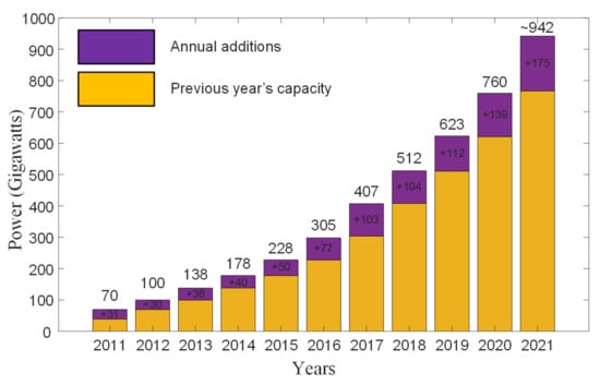
Figure 1.
Solar PV global capacity and annual additions, 2011–2021 [3].
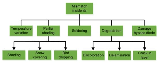
Figure 2.
Mismatch incidents and their causes.
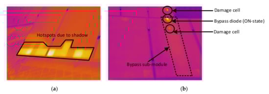
Figure 3.
Infrared images: (a) shadow from front row PV modules and (b) damage PV cell in a PV module.
Usually, a PV module consists of series-connected solar PV cells; as a result, a mismatch caused by a single cell affects the whole PV module. In order to limit the effect of mismatch, there are various solutions, e.g., bypass diodes method [18] (shown in Figure 4a), DC optimizers [19,20] (shown in Figure 4b), and differential power processing (DPP) converters [21,22,23,24,25] (shown in Figure 4c). The traditional method to limit mismatch effects is the inclusion of bypass diodes into the PV module. Bypass diodes are parallel-connected to a group of series-connected PV cells [26], dividing the whole PV module into more sub-modules.
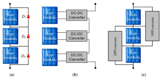
Figure 4.
Mismatch reduction techniques: (a) bypass diodes, (b) DC optimizers, and (c) differential power processing (DPP) converters.
Despite the optimal solution consisting of the connection of a bypass diode across each PV cell, the number of bypass diodes, or the number of PV cells in each sub-module, results in a tradeoff between PV cell protection against hotspot and techno-economical issues; from this perspective, it is not necessary to connect a bypass diode across each cell [27]. Normally, 60–72 PV cells are connected in a series in commercially used PV modules, and they consist of three bypass diodes [28]. Each bypass diode is connected across 20–24 series-connected PV cells, which is known as the PV sub-module, as shown in Figure 4a. Bypass diodes become forward biased when the voltage across the group of mismatched cells reverts; this prevents the sub-module to operate as a load. Bypass diodes protect PV cells from partial shading scenarios, but being passive and uncontrollable power semiconductor devices, they do not allow any kind of regulation and optimization of energy production. Additionally, the bypass diodes also cause power losses when they are in ON-state.
In addition to bypass diodes methodology, distributed maximum power point tracker (dMPPT) methods have been used to eliminate the electrical characteristic mismatch problems in the solar PV systems [29,30,31,32]. The commonly used dMPPT methodologies are DC optimizers [33,34,35] and DPP converters [24,36,37,38,39,40]. The general schematic of DC optimizer and DPP converters are shown in Figure 4b,c. In DC optimizers each PV sub-module is connected to a DC-DC converter, which processes a complete power, and each PV sub-module is operating at its maximum power point (MPP). However, the DC optimizer’s power losses reduce the overall efficiency when there is no mismatch [41], which is when the DC optimizers would not be necessary. Additionally, DC optimizers also increase the cost of the system and could reduce long-term reliability. PV modules, including DC optimizers, may be suitable solutions for residential PV systems, which are prone to heavy mismatch losses due to partial shading, but they are not the best solution for large PV generators due to the increased cost and the low probability of mismatch.
The DPP converters methodology represents an evolution that allows overcoming some drawbacks of the DC optimizers. DPP converters process a fraction of the whole power generated by the PV sub-modules, which is known as mismatched power, instead of full power as compared to DC optimizers. Therefore, DPP converter topologies provide an overall improved efficiency by using smaller and low-cost power electronic solutions with a rating equal to the mismatched power. Furthermore, the DPP converters maintain a constant voltage across the PV sub-modules. This will reduce the hotspot issues in the PV system, which occur when the negative voltage is applied to a PV cell. Additionally, the overall performance and lifetime of the system are improved. The converters in the DPP configuration must be controlled together, instead of DC optimizers that operate independently.
There are several advantages of DC optimizers and DPP converters as compared to traditional architecture, i.e., the bypass diode method, which is highlighted and compared in many research studies [42]. However, the comparison among three of these topologies is missing along with the effect of mismatch, which is not discussed in much detail by considering the cell level. The objective of this study is to cover several questions, i.e., the detailed comparison among three mismatch mitigation techniques, validation of simulation results by comparison through real PV systems, and analysis of voltage distribution at a cell level to analyze the effect of mismatch among DC optimizers, DPP converters, and bypass diode methodologies.
The paper is organized as follows: Section 2 describes the PV architectures/mitigation techniques that are taken as a reference for comparison; Section 3 introduces the PV system and SolarTech Lab; Section 4 introduces the evaluation procedure and mismatch scenarios that are used for the evaluation; Section 5 analyzes the results and the main findings; and in the end, Section 6 presents the conclusions of the study.
2. Mismatch Mitigation Methodologies
Various PV architectures/mitigation techniques/methodologies that are taken as a reference for comparison are described in detail in this section. These methodologies have variations in the circuit arrangement and working principle. However, these methodologies are working on the same issues to reduce the effect of mismatch and maximize the PV system output power. These various mismatch reduction/mitigation techniques are discussed below.
2.1. Bypass Diode Methodology
In commercial PV modules, parallel-connected bypass diodes are installed and divide the PV module into more sub-modules, as shown in Figure 5a. Bypass diodes reduce the mismatch effect mainly under partial shading scenarios; however, they also can be effective in other non-ideal conditions, which are discussed above. Without mismatch, bypass diodes are reverse biased and the same current Imod flows through all the sub-modules, as depicted in Figure 5a. When partial shading affects a sub-module, its photogenerated current Imod1 drops, and the voltage across its terminals usually becomes negative (if there was no bypass diode); the latter condition depends on the actual operation of the unshaded cells and the load connected to the whole PV module. As soon as the voltage across the shaded PV sub-module tends to become negative, the corresponding bypass diode becomes forward biased; the shaded PV sub-module is bypassed and current Ibyp flows through the bypass diode, as shown in Figure 5b. However, the different states of the bypass diodes result in more peaks in the power-voltage (P-V) curve [43], as shown in Figure 5c; the maximum number of peaks corresponds to the number of bypass diodes. Hence, the traditional maximum power point tracking (MPPT) techniques are generally not capable of differentiating among local and global power peaks in the P-V curve of PV systems, which also impacts the performance of the whole system. Therefore, the global maximum power point tracking (GMPPT) algorithms are required to identify the global power peak from many local peaks [44,45,46,47,48,49].
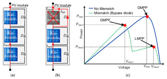
Figure 5.
Solar PV module with three bypass diodes: (a) no shading, (b) sub-module1 shaded, and (c) power-voltage (P-V) characteristic curve under mismatch.
2.2. DC Power Optimizers
The DC power optimizers are DC-DC converters, which are designed to extract maximum power from a solar PV sub-module/module using MPPT. Normally, the DC optimizers are connected with each PV module or sub-module, as shown in Figure 6. The output coming from each of these DC optimizers is connected in series with each other. Overall, several optimizers are arranged in series making a string connection (see Figure 6).
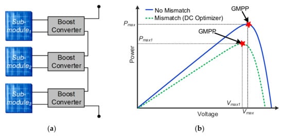
Figure 6.
(a) DC power optimizer with boost converters and (b) power-voltage (P-V) characteristic curve under mismatch.
Afterward, the string of series-connected DC optimizers is connected to the main central inverter. The number of optimizers is designed by considering that the output voltage of the string matches with the input voltage range of the central inverter. The P-V characteristic curve of systems with DC optimizer is shown in Figure 6b, which depicts that in DC optimizer there is only a single power peak named as a global maximum power point (GMPP) instead of multiple peaks as in bypass diode.
Various DC-DC converter topologies can be used in DC optimizers. Normally, buck, boost, and buck-boost converter topologies are considered for DC optimizers. In this study, a boost converter is used, and each converter is equipped with MPPT tracking capability to extract maximum power at the sub-module level. The working principle of the boost converter is given in [50,51].
2.3. Differential Power Processing (DPP) Converter
The main feature of the DPP methodology is that the power converters only process the mismatched power instead of the full power as compared to DC power optimizers. In the literature, there are various DPP converter topologies [52,53,54,55,56,57]. In these DPP converters, only a fraction of the whole power generated by each sub-module, the so-called mismatched power, is processed by the converters, reducing the power loss in DPP converters and, therefore, increasing the overall efficiency. In [54,55], it is mentioned that the DPP converters configuration allows obtaining about a 7% higher efficiency than the ones achieved by using DC optimizers. As the DC optimizer configuration, the DPP converter configuration does not result in the multiple-peak P-V curve, which arises in the bypass diode configuration, avoiding the issue related to the search for the global maximum power peak.
Furthermore, there are various kinds of DPP converter topologies from which the PV is connected to another PV (PV-PV) DPP converter topologies, and they are the most famous because they require fewer power converters than the other DPP converters. Additionally, the PV-PV DPP converters are independent of bus voltage and do not need to withstand the high-voltage stresses, as compared to other DPP topologies. Generally, each DPP converter is connected between two PV sub-modules, as shown in Figure 4c. Furthermore, these DPP converters are bidirectional and can supply as well as remove the current, which is needed for PV sub-modules to maintain their operation at their MPPs. Some of the commonly discussed PV-PV DPP topologies are energy recovery [58], buck-boost [59], and switched-capacitor (SC) [60]. In this study, SC-based DPP converter topology is considered for analysis, and the general schematic of the topology is shown in Figure 7a. The SC-based DPP topology has two states of operation, as shown in Figure 7b (state/mode 1) and in Figure 7c (state/mode 2). In state 1, the even-numbered switches (Q2, Q4, and Q6) are ON and the odd-numbered switches are OFF (Q1, Q3, and Q5), as depicted in Figure 7b. During that state, the mismatched energy is stored by the capacitors (C). However, this energy is released in the second state/mode of operation of the SC-based DPP converter, where the odd-numbered switches (Q1, Q3, and Q5) are ON and even-numbered (Q2, Q4, and Q6) are OFF, as shown in Figure 7c. The more detailed working principle is given in [60].
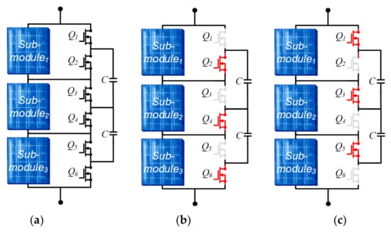
Figure 7.
Switched-capacitor (SC)-based differential power processing (DPP) converter: (a) general schematic, (b) switching state/mode 1, and (c) switching state/mode 2.
3. Introduction of the PV System and SolarTechLab Test Facility
This study makes use of real data collected at the SolarTechLab, which is a research laboratory located on the rooftop of the Department of Energy of Politecnico di Milano, Milan, Italy [61]. Different technologies of PV modules, which are monocrystalline and polycrystalline silicon, CIGS, and thin-film, are installed at the SolarTechLab. Some silicon PV modules are equipped with thermal recovery systems. All PV modules are oriented toward the south-east, the azimuth angle is −6°30′ (0° in the south direction and azimuth increase clockwise), and the tilt of most structures is 30°. The latter pair of angles define the orientation of the conventional plane of array (POA) of the test facility. From the electrical point of view, each PV module is connected with the low-voltage AC distribution grid (230 V single phase, 50 Hz) through micro-inverters; this configuration allows to avoid mismatches between PV modules that are operated individually at their specific maximum power point. In addition to the power conversion function, micro-inverters make available several measurements, such as voltage, current and power on the DC side, RMS voltage, RMS current, active power, power factor, and frequency on the AC side; their averaged values per minute are stored in a database.
The environmental conditions are measured with a meteorological station, including solar irradiance sensors, wind speed and direction sensors, temperature and humidity sensors, and rain collector [62], as shown in Figure 8. Global horizontal irradiance (GHI), POA, and diffuse horizontal irradiance (DHI) are measured using spectrally flat pyranometers, in which an occultation band fits out the pyranometer that measures the DHI. The metrological characteristics and orientation of irradiance sensors are reported in Table 1. The meteorological station makes measurements of each environmental parameter every 10 s, and then the average, maximum, minimum, and standard deviations over a 10-min time range are calculated and stored in the meteorological database.
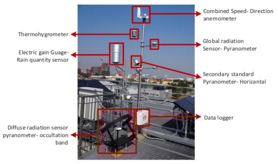
Figure 8.
SolarTechLab weather station.

Table 1.
Technical specifications of pyranometers connected to the weather station and available in the test facility.
To compare different mismatch reduction techniques with a real PV system in a field, the group of five 245 Wp monocrystalline PV modules, shown in Figure 9, is considered [63]. These modules are identified by the labels Array 2.1, Array 2.2, Array 2.3, Array 2.4, and Array 2.5, and their ratings are given in Table 2. The DC power recordings taken during the year 2017 are considered and compared with the model presented in the next section by considering similar irradiance and temperature profiles.
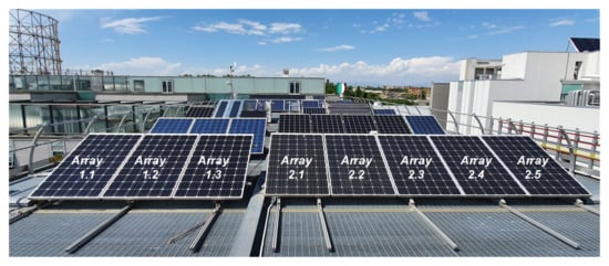
Figure 9.
PV modules installed at SolarTechLab, Politecnico di Milano.
Table 2.
Ratings of the PV module under test.
4. Evaluation Procedure and Mismatch Scenarios
For the performance evaluation of the traditional bypass diode, DC power optimizer, and DPP converter, a model is built in MATLAB, which is shown in Figure 10. In this model, each PV system consists of a single PV module, which compromises three PV sub-modules. The pairs of terminals of these PV sub-modules are labeled T1, T2, and T3, as shown in Figure 11. These devices for the mismatch reduction/mitigation methodologies are connected at these pairs of terminals. Three models are evaluated by creating various non-ideal conditions or mismatched scenarios, as shown in Figure 11. Overall, a total of twelve mismatched scenarios are created by considering various real-time expected shading scenarios discussed below in these studies, e.g., a shadow from the front row of PV modules, pole, etc.
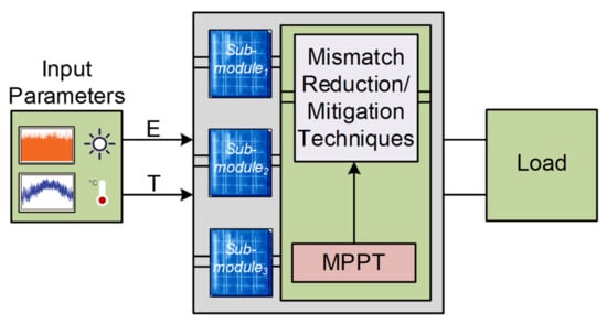
Figure 10.
General layout of MATLAB model.
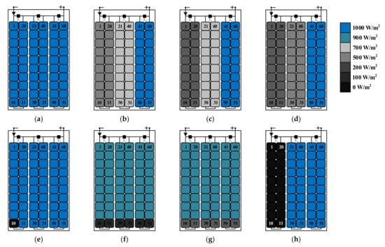
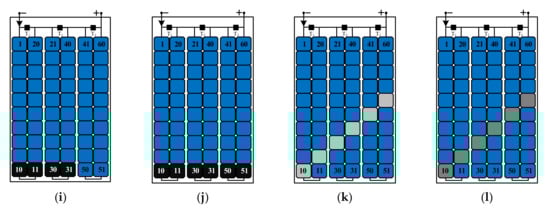
Figure 11.
Mismatch scenarios: (a) Scenario 1, (b) Scenario 2, (c) Scenario 3, (d) Scenario 4, (e) Scenario 5, (f) Scenario 6, (g) Scenario 7, (h) Scenario 8, (i) Scenario 9, (j) Scenario 10, (k) Scenario 11, and (l) Scenario 12.
Furthermore, the ratings of the solar PV module used in the models are exactly the modules used at SolarTechLab, Politecnico di Milano, and given in Table 2. Additionally, the model also is compared with the results obtained from the solar PV system installed at SolarTechLab, Politecnico di Milano, by using the similar irradiance and temperature profiles obtained from the weather station. The obtained temperature profile was in ambient temperature (Tamb), and it was converted to cell temperature (Tc) by using Equation (1) [63].
Here, NOCT is the nominal operating cell temperature, Tamb@NOCT represents the ambient temperature at NOCT, and GNOCT is irradiance at NOCT.
5. Results and Discussion
In this section, a comparison among three different mismatch reduction/prevention methodologies, which are bypass diodes (Figure 5), DC optimizers (Figure 6), and the switched-capacitor-based DPP (Figure 7), is presented.
These methodologies are applied at the sub-module level, as depicted in Figure 11. The rating of a PV module used for the evaluation is given in Table 2. The PV module consists of three sub-modules named sub-module1, sub-module2, and sub-module3. Each PV sub-module comprises 20 series-connected PV cells, as shown in Figure 11. The partial shading scenarios that are considered for the evaluation of the three methodologies under similar conditions are given in Figure 11. The mismatched scenarios were developed by varying the irradiances over the PV cells.
The results obtained from the above-discussed three systems under various mismatched scenarios are shown in Figure 12, which shows the amount of power generated and lost under specific scenarios by these three methodologies. Considering the mismatch in Scenario 3 in Figure 12, the power generated by the DPP converter (152.23 W) was more than the other two topologies (120.44 W for the bypass diode method and 136.34 W for the DC optimizer method). The result of the lower power losses in DPP converters is due to only processing of mismatched power. However, in Scenario 5, the overall power from the DC optimizer was 157.61 W while the power from the DPP converter and bypass diode was 156.44 W and 154.02, respectively. The output power in the DPP converter is slightly lower than DC optimizer because the power is flowing from the bottom to the top like a ladder. Therefore, overall power was affected as one of the PV cells in a sub-module completely blocks the flow of power, which in turn also affects the power of the other two PV sub-modules connected in series. Similarly, the PV sub-module is completely circumvented by a bypass diode in Scenario 5. Therefore, the power is completely lost from this sub-module. Furthermore, in Scenario 10 shown in Figure 11j the bottom two cells of each PV sub-module are completely covered (irradiance over these six cells is 0 W/m2). The output power in Scenario 10 is 0 W for all three mismatch reduction/mitigation techniques, which can be seen in Figure 12b, because, in any scenario, the completely shaded cell constrains the sub-module current to be 0 A.
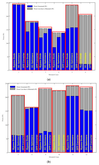
Figure 12.
Power generated and lost under mismatch cases: (a) Cases 1–6 and (b) Cases 7–10.
The voltage across the terminals T1, T2, and T3 are given in Table 3, Table 4 and Table 5 for bypass diode, DC optimizer, and DPP converter, respectively. These tables show the results from Scenarios 5, 9, 10, 11, and 12, where the voltage stresses are much more severe across the shaded PV cell(s). Under these mismatched scenarios, the voltage across the individual cells is analyzed, which gives the voltage distribution among the cells within a PV sub-module. In Table 3, Table 4 and Table 5, the voltages VT1, VT2, and VT3 are the voltages at the terminals of the sub-modules, T1, T2, and T3, respectively. Similarly, Vnscells, are the voltage across the non-shaded cells in a sub-module, while Vscell is the voltage across the shaded cell(s) within a sub-module for Scenarios 5, 9, 10, 11, and 12, as shown in Figure 11. It can be seen from the Tables, the Vscell for Scenario 5 is −13.62 V, −12.92 V, and −4.48 V, respectively. It shows that the reverse voltage in DPP converter topology is reduced to 32.89% as compared to bypass diode and 27.75% compared to DC optimizers. Similarly, the reverse voltage across the shaded cells is reduced by 28.17% and 23.72%, using the DPP converter as compared to the bypass diode and DC optimizer methodology, respectively. Overall, the reverse voltage reduction will help to reduce the stresses over the shaded cells along with the hotspot temperature, which will help to improve the life of the module thereafter and the overall PV system life.
Table 3.
Voltage across shaded PV sub-modules and PV cell(s) equipped with bypass diode.
Table 4.
Voltage across shaded PV sub-modules and PV cell(s) equipped with DC optimizers.
Table 5.
Voltage across shaded PV sub-modules and PV cell(s) equipped with DPP converters.
The model also is verified through the five different PV systems installed at SolarTechLab. The PV modules output is recorded and compared under the same irradiance and temperature with the PV model built-in MATLAB, as shown in Figure 10. The PV models consist of similar systems equipped with bypass diode, DC power optimizer, and DPP converter. For evaluation, four different irradiance profiles of various days are used from a year, which is shown in Figure 13. The power output of the system under these irradiance and temperature profiles at a specific instant of the day is given in Figure 14, Figure 15, Figure 16, and Figure 17 for 1 January, 6 June, 8 June, and 1 September, respectively. The maximum output power for the 1st January was achieved at 12:00 (noon) hour when the recorded irradiance was 683W/m2 by the weather system at SolarTechLab. The output powers are 152.21 W from Array 2.1, 156.46 W from Array 2.2, 149.94 W from Array 2.3, 153.27 W from Array 2.4, and 150.21 W from Array 2.5. Similarly, the output power from the developed models is 157.03 W for the bypass diode system, 155.39 W for the DC optimizer system, and 156.97 W for the DPP converter system, as shown in Figure 14. The results in Figure 14, as well as in Figure 15, Figure 16 and Figure 17, depict that the real system and model performance is close.
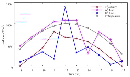
Figure 13.
Recorded irradiance profile.
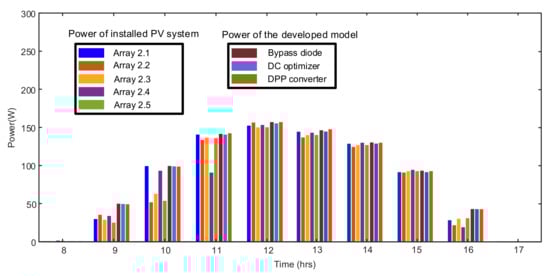
Figure 14.
PV system outputs over a day under irradiance data on 1 January shown in Figure 13.
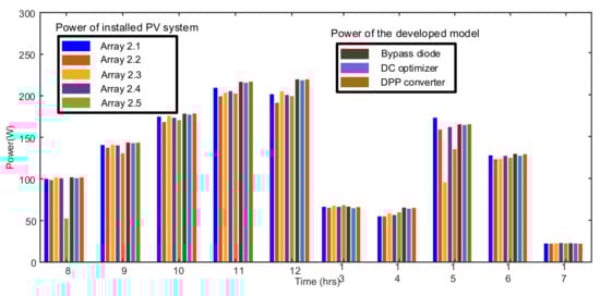
Figure 15.
PV system outputs over a day under irradiance data on 6 June shown in Figure 13.
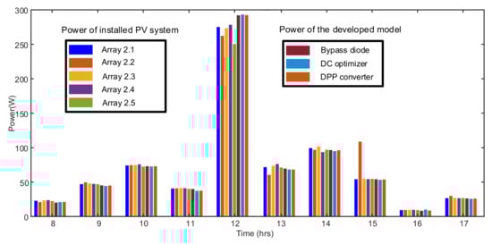
Figure 16.
PV system outputs over a day under irradiance data on 8th June shown in Figure 13.
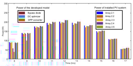
Figure 17.
PV system outputs over a day under irradiance data on 1 September shown in Figure 13.
In continuation, a comparison among the above-discussed topologies in terms of the number of electrical components, complexity in their circuit, analysis of the cost of the topology, the complexity required to control the converter, requirement of local or global MPPT control strategy, and losses/overall efficiency are given in Table 6. The parameters discussed in Table 6 depend upon the number of circuit components in each topology, including both active as well as passive. The increase in circuit components also enhances the control complexity, which becomes a reason for using complex control strategies. The number of the component includes both active and passive circuit elements of the mismatch mitigation topologies, which are based on the implementation of a single solar PV module containing three series-connected PV sub-modules. As depicted in Table 6, 12x components are required for DC optimizers and 8x for SC-based DPP topology, where p is the number of PV modules in the system. Overall, the cost and losses in the system are increasing because they are directly dependent on the number of electrical components, i.e., passive as well as active. Finally, the efficiency of the topologies depends on the overall power seen at the output after all losses, considering the system is under mismatch and no mismatch. Furthermore, the number of bypass diodes, capacitors, inductors, and MOSFETs required for the 2.2 kW PV system equipped with bypass diode, DC optimizer, and DPP converter methodologies are given in Table 7. Overall, there are nine 245 W PV modules in the system, and the total electrical component count distribution among them is shown in Figure 18. In Figure 18, the maximum numbers of components are in DC optimizers (52%), while the bypass diode and DPP converter are 13% and 35%, respectively.
Table 6.
Evaluation of various mismatch reduction/mitigation methodologies for a PV module consisting of three sub-modules.
Table 7.
Number of components required for 2.2 kW system containing nine 245 W PV modules and equipped with bypass diodes, DC optimizers, or DPP converters.
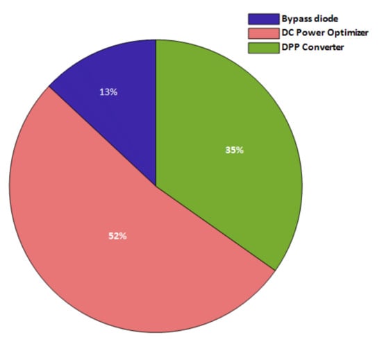
Figure 18.
Total electrical component count distribution among bypass diode, DC optimizers, and DPP converter in 2.2 kW PV system.
6. Conclusions
In this study, three various mismatch reduction/mitigation techniques, i.e., bypass diode, DC power optimizer, and differential power processing (DPP) converter for solar PV modules, were discussed, compared, and evaluated through models built in MATLAB. The models were evaluated with an infield-installed solar PV system. The presented outcomes of the study confirm that the traditional bypass diodes are simple in operation and are more economical but can only limit the effect of mismatch to some extent, instead of mitigating them as DC optimizers and DPP converters. However, the DC optimizers and DPP converters maximize the output power, but the system becomes complex and expensive. It is confirmed from the results that the DPP converters perform better in most of the mismatch conditions as compared to DC optimizers. However, under the severe mismatch, the performance of DPP converters is degraded.
These solutions are analyzed in detail, which shows that the reverse voltage across the shaded cells is much worse with the bypass diodes and DC optimizers. However, the DPP converter greatly reduces the reverse voltage across the shaded cell(s) up to 32.89%, when compared to the bypass diode scenarios and 27.75% compared to DC optimizers. These topologies also were analyzed in terms of electrical components, cost, complexity, operating strategy, local maxima, and efficiency, which show that for large PV systems, it is better to use bypass diodes because of the lower cost and lower chances of mismatch. However, it is better to use DPP and DC optimizers in small PV systems.
Author Contributions
Conceptualization, K.A.K.N., T.K., A.D., Y.Y. and S.L.; methodology, K.A.K.N., T.K., A.D., Y.Y. and S.L.; validation, K.A.K.N., T.K., A.D., Y.Y. and S.L.; writing—original draft preparation, K.A.K.N.; writing—review and editing, K.A.K.N., T.K., A.D., Y.Y. and S.L.; visualization, K.A.K.N., T.K., A.D., Y.Y. and S.L.; supervision, T.K., A.D., Y.Y. and S.L. All authors have read and agreed to the published version of the manuscript.
Funding
This research received no external funding.
Conflicts of Interest
The authors declare no conflict of interest.
References
- Sivaram, V.; Kann, S. Solar Power Needs a More Ambitious Cost Target. Nat. Energy 2016, 1, 16036. [Google Scholar] [CrossRef]
- Nemet, G.F. Beyond the Learning Curve: Factors Influencing Cost Reductions in Photovoltaics. Energy Policy 2006, 34, 3218–3232. [Google Scholar] [CrossRef]
- GSR2022_Full_Report.Pdf. Available online: https://www.ren21.net/wp-content/uploads/2019/05/GSR2022_Full_Report.pdf (accessed on 1 May 2022).
- Obeidat, F. A Comprehensive Review of Future Photovoltaic Systems. Sol. Energy 2018, 163, 545–551. [Google Scholar] [CrossRef]
- Mäki, A.; Valkealahti, S. Power Losses in Long String and Parallel-Connected Short Strings of Series-Connected Silicon-Based Photovoltaic Modules Due to Partial Shading Conditions. IEEE Trans. Energy Convers. 2012, 27, 173–183. [Google Scholar] [CrossRef]
- Potnuru, S.R.; Pattabiraman, D.; Ganesan, S.I.; Chilakapati, N. Positioning of PV Panels for Reduction in Line Losses and Mismatch Losses in PV Array. Renew. Energy 2015, 78, 264–275. [Google Scholar] [CrossRef]
- Manganiello, P.; Balato, M.; Vitelli, M. A Survey on Mismatching and Aging of PV Modules: The Closed Loop. IEEE Trans. Ind. Electron. 2015, 62, 7276–7286. [Google Scholar] [CrossRef]
- Vumbugwa, M.; Vorster, F.J.; Crozier McCleland, J.L.; van Dyk, E.E. Effects of Changing Partial Cell Shading on the Electrical and Thermal Characteristics of Crystalline Silicon Photovoltaic Module. Sol. Energy 2022, 240, 147–156. [Google Scholar] [CrossRef]
- Sattar, A.; Farooq, M.; Amjad, M.; Saeed, M.A.; Nawaz, S.; Mujtaba, M.A.; Anwar, S.; El-Sherbeeny, A.M.; Soudagar, M.E.M.; Bandarra Filho, E.P.; et al. Performance Evaluation of a Direct Absorption Collector for Solar Thermal Energy Conversion. Energies 2020, 13, 4956. [Google Scholar] [CrossRef]
- Kabir, E.; Kumar, P.; Kumar, S.; Adelodun, A.A.; Kim, K.-H. Solar Energy: Potential and Future Prospects. Renew. Sustain. Energy Rev. 2018, 82, 894–900. [Google Scholar] [CrossRef]
- Villalva, M.G.; Gazoli, J.R.; Filho, E.R. Comprehensive Approach to Modeling and Simulation of Photovoltaic Arrays. IEEE Trans. Power Electron. 2009, 24, 1198–1208. [Google Scholar] [CrossRef]
- Kaushika, N.D.; Rai, A.K. An Investigation of Mismatch Losses in Solar Photovoltaic Cell Networks. Energy 2007, 32, 755–759. [Google Scholar] [CrossRef]
- Deline, C. Partially Shaded Operation of Multi-String Photovoltaic Systems. In Proceedings of the 2010 35th IEEE Photovoltaic Specialists Conference, Honolulu, HI, USA, 20–25 June 2010; pp. 000394–000399. [Google Scholar]
- Piccoli, E.; Dama, A.; Dolara, A.; Leva, S. Experimental Validation of a Model for PV Systems under Partial Shading for Building Integrated Applications. Sol. Energy 2019, 183, 356–370. [Google Scholar] [CrossRef]
- Kim, K.A.; Krein, P.T. Hot Spotting and Second Breakdown Effects on Reverse I-V Characteristics for Mono-Crystalline Si Photovoltaics. In Proceedings of the 2013 IEEE Energy Conversion Congress and Exposition, Denver, CO, USA, 15–19 September 2013; pp. 1007–1014. [Google Scholar]
- Rossi, D.; Omaña, M.; Giaffreda, D.; Metra, C. Modeling and Detection of Hotspot in Shaded Photovoltaic Cells. IEEE Trans. Very Large Scale Integr. (VLSI) Syst. 2015, 23, 1031–1039. [Google Scholar] [CrossRef] [Green Version]
- Ahsan, S.; Niazi, K.A.K.; Khan, H.A.; Yang, Y. Hotspots and Performance Evaluation of Crystalline-Silicon and Thin-Film Photovoltaic Modules. Microelectron. Reliab. 2018, 88–90, 1014–1018. [Google Scholar] [CrossRef]
- Silvestre, S.; Boronat, A.; Chouder, A. Study of Bypass Diodes Configuration on PV Modules. Appl. Energy 2009, 86, 1632–1640. [Google Scholar] [CrossRef]
- Ramli, M.Z.; Salam, Z. Performance Evaluation of Dc Power Optimizer (DCPO) for Photovoltaic (PV) System during Partial Shading. Renew. Energy 2019, 139, 1336–1354. [Google Scholar] [CrossRef]
- Chu, G.; Wen, H. A Reliability Assessment of Submodule-Level Distributed Power Electronic Solution in Photovoltaic Generation System. In Proceedings of the 2020 IEEE 9th International Power Electronics and Motion Control Conference (IPEMC2020-ECCE Asia), Nanjing, China, 29 November–2 December 2020; pp. 1740–1745. [Google Scholar]
- Shenoy, P.S.; Kim, K.A.; Johnson, B.B.; Krein, P.T. Differential Power Processing for Increased Energy Production and Reliability of Photovoltaic Systems. IEEE Trans. Power Electron. 2013, 28, 2968–2979. [Google Scholar] [CrossRef]
- Pascual, C.; Krein, P.T. Switched Capacitor System for Automatic Series Battery Equalization. In Proceedings of the Proceedings of APEC 97—Applied Power Electronics Conference, Atlanta, GA, USA, 27 February 1997; Volume 2, pp. 848–854. [Google Scholar]
- Niazi, K.A.K.; Yang, Y.; Sera, D. Review of Mismatch Mitigation Techniques for PV Modules. IET Renew. Power Gener. 2019, 13, 2035–2050. [Google Scholar] [CrossRef]
- Khan Niazi, K.A.; Yang, Y.; He, J.; Khan, A.Z.; Sera, D. Switched-Capacitor-Inductor-Based Differential Power Converter for Solar PV Modules. In Proceedings of the 2019 IEEE Energy Conversion Congress and Exposition (ECCE), Baltimore, MD, USA, 29 September–3 October; pp. 4613–4618.
- Niazi, K.A.K.; Yang, Y.; Kerekes, T.; Sera, D. A Simple Mismatch Mitigating Partial Power Processing Converter for Solar PV Modules. Energies 2021, 14, 2308. [Google Scholar] [CrossRef]
- Niazi, K.A.K.; Yang, Y.; Spataru, S.V.; Mutarraf, M.U.; Sera, D. Experimental benchmarking of partial shading effect on thin-film and crystalline-silicon solar photovoltaic modules. In Proceedings of the 36th European Photovoltaic Solar Energy Conference and Exhibition, Marseille, France, 9–13 September 2019. [Google Scholar]
- Pannebakker, B.B.; de Waal, A.C.; van Sark, W.G.J.H.M. Photovoltaics in the Shade: One Bypass Diode per Solar Cell Revisited. Prog. Photovolt. Res. Appl. 2017, 25, 836–849. [Google Scholar] [CrossRef] [Green Version]
- Etarhouni, M.; Chong, B.; Zhang, L. A Combined Scheme for Maximising the Output Power of a Photovoltaic Array under Partial Shading Conditions. Sustain. Energy Technol. Assess. 2022, 50, 101878. [Google Scholar] [CrossRef]
- Femia, N.; Lisi, G.; Petrone, G.; Spagnuolo, G.; Vitelli, M. Distributed Maximum Power Point Tracking of Photovoltaic Arrays: Novel Approach and System Analysis. IEEE Trans. Ind. Electron. 2008, 55, 2610–2621. [Google Scholar] [CrossRef] [Green Version]
- Khan, O.; Xiao, W. Review and Qualitative Analysis of Submodule-Level Distributed Power Electronic Solutions in PV Power Systems. Renew. Sustain. Energy Rev. 2017, 76, 516–528. [Google Scholar] [CrossRef]
- Salam, Z.; Ramli, M.Z. Distributed Maximum Power Point Tracker for Additional Energy Harvesting during Partial Shading of PV System. In Proceedings of the 2015 First Workshop on Smart Grid and Renewable Energy (SGRE), Doha, Qatar, 22–23 March 2015; pp. 1–5. [Google Scholar]
- Li, C.; Yang, Y.; Fan, F.; Xia, L.; Peng, P.; Wang, Y.; Zhang, K.; Wei, H. A Novel Methodology for Partial Shading Diagnosis Using t Electrical Parameters of Photovoltaic Strings. IEEE J. Photovolt. 2022, 1–9. [Google Scholar] [CrossRef]
- Deline, C.; MacAlpine, S. Use Conditions and Efficiency Measurements of DC Power Optimizers for Photovoltaic Systems. In Proceedings of the 2013 IEEE Energy Conversion Congress and Exposition, Denver, CO, USA, 15–19 September 2013; pp. 4801–4807. [Google Scholar]
- De Souza Silva, J.L.; Soeiro Moreira, H.; Bastos de Mesquita, D.; Gomes dos Reis, M.V.; Gradella Villalva, M. Study of Power Optimizers for Grid-Connected Photovoltaic Systems. IEEE Lat. Am. Trans. 2019, 17, 127–134. [Google Scholar] [CrossRef]
- Sinapis, K.; Tsatsakis, K.; Dörenkämper, M.; van Sark, W.G.J.H.M. Evaluation and Analysis of Selective Deployment of Power Optimizers for Residential PV Systems. Energies 2021, 14, 811. [Google Scholar] [CrossRef]
- Friesen, G.; Ossenbrink, H.A. Capacitance Effects in High-Efficiency Cells. Sol. Energy Mater. Sol. Cells 1997, 48, 77–83. [Google Scholar] [CrossRef]
- Peter, P.K.; Agarwal, V. Current Equalization in Photovoltaic Strings With Module Integrated Ground-Isolated Switched Capacitor DC–DC Converters. IEEE J. Photovolt. 2014, 4, 669–678. [Google Scholar] [CrossRef]
- Uno, M.; Kukita, A. Single-Switch Voltage Equalizer Using Multistacked Buck–Boost Converters for Partially Shaded Photovoltaic Modules. IEEE Trans. Power Electron. 2015, 30, 3091–3105. [Google Scholar] [CrossRef]
- Flores-Bahamonde, F.; Rojas, J.; Kouro, S.; Llor, A.M.; Rojas, C.A.; Perez, M.A. Sub-Modular Power Optimizers Based on Partial Power Converters for Utility Scale PV Plants. In Proceedings of the IECON 2019—45th Annual Conference of the IEEE Industrial Electronics Society, Lisabon, Portugal, 14–17 October 2019; Volume 1, pp. 4423–4428. [Google Scholar]
- Niazi, K.A.K.; Yang, Y.; Kerekes, T.; Sera, D. Reconfigurable Distributed Power Electronics Technique for Solar PV Systems. Electronics 2021, 10, 1121. [Google Scholar] [CrossRef]
- Jeong, H.; Lee, H.; Liu, Y.; Kim, K.A. Review of Differential Power Processing Converter Techniques for Photovoltaic Applications. IEEE Trans. Energy Convers. 2019, 34, 351–360. [Google Scholar] [CrossRef]
- Khan Niazi, K.A.; Yang, Y.; Khan, H.A.; Sera, D. Performance Benchmark of Bypassing Techniques for Photovoltaic Modules. In Proceedings of the 2019 IEEE Applied Power Electronics Conference and Exposition (APEC), Anaheim, CA, USA, 17–19 March 2019; pp. 3164–3168. [Google Scholar]
- Belhachat, F.; Larbes, C. A Review of Global Maximum Power Point Tracking Techniques of Photovoltaic System under Partial Shading Conditions. Renew. Sustain. Energy Rev. 2018, 92, 513–553. [Google Scholar] [CrossRef]
- Nasir, M.; Zia, M.F. Global Maximum Power Point Tracking Algorithm for Photovoltaic Systems under Partial Shading Conditions. In Proceedings of the 2014 16th International Power Electronics and Motion Control Conference and Exposition, Antalya, Türkiye, 21–24 September 2014; pp. 667–672. [Google Scholar]
- Liu, Y.-H.; Liu, C.-L.; Huang, J.-W.; Chen, J.-H. Neural-Network-Based Maximum Power Point Tracking Methods for Photovoltaic Systems Operating under Fast Changing Environments. Sol. Energy 2013, 89, 42–53. [Google Scholar] [CrossRef]
- Dolara, A.; Grimaccia, F.; Mussetta, M.; Ogliari, E.; Leva, S. An Evolutionary-Based MPPT Algorithm for Photovoltaic Systems under Dynamic Partial Shading. Appl. Sci. 2018, 8, 558. [Google Scholar] [CrossRef] [Green Version]
- Hayder, W.; Ogliari, E.; Dolara, A.; Abid, A.; Ben Hamed, M.; Sbita, L. Improved PSO: A Comparative Study in MPPT Algorithm for PV System Control under Partial Shading Conditions. Energies 2020, 13, 2035. [Google Scholar] [CrossRef]
- Aghaei, M.; Dolara, A.; Grimaccia, F.; Leva, S.; Kania, D.; Borkowski, J. Experimental Comparison of MPPT Methods for PV Systems under Dynamic Partial Shading Conditions. In Proceedings of the 2016 IEEE 16th International Conference on Environment and Electrical Engineering (EEEIC), Florence, Italy, 7–10 June 2016; pp. 1–6. [Google Scholar]
- Dolara, A.; Leva, S.; Magistrati, G.; Mussetta, M.; Ogliari, E.; Arvind, R.V. A Novel MPPT Algorithm for Photovoltie Systems under Dynamic Partial Shading—Recurrent Scan and Track Method. In Proceedings of the 2016 IEEE International Conference on Renewable Energy Research and Applications (ICRERA), Birmingham, UK, 20–23 November 2016; pp. 1122–1127. [Google Scholar]
- Sera, D.; Mathe, L.; Blaabjerg, F. Distributed Control of PV Strings with Module Integrated Converters in Presence of a Central MPPT. In Proceedings of the 2014 IEEE Energy Conversion Congress and Exposition (ECCE), Pittsburgh, PA, USA, 14–18 September 2014; pp. 1–8. [Google Scholar]
- Al-Smadi, M.K.; Mahmoud, Y. Photovoltaic Module Cascaded Converters for Distributed Maximum Power Point Tracking: A Review. IET Renew. Power Gener. 2020, 14, 2551–2562. [Google Scholar] [CrossRef]
- Niazi, K.A.K.; Yang, Y.; Sera, D. Intrinsic-Capacitance-Based Differential Power Processing for Photovoltaic Modules. In Proceedings of the 2020 IEEE 21st Workshop on Control and Modeling for Power Electronics (COMPEL), Aalborg, Denmark, 9–12 November 2020; pp. 1–6. [Google Scholar]
- Chang, A.H.; Avestruz, A.; Leeb, S.B. Capacitor-Less Photovoltaic Cell-Level Power Balancing Using Diffusion Charge Redistribution. IEEE Trans. Power Electron. 2015, 30, 537–546. [Google Scholar] [CrossRef]
- Liu, C.; Zheng, Y.; Lehman, B. PV Panel to PV Panel Transfer Method for Modular Differential Power Processing. IEEE Trans. Power Electron. 2022, 37, 4764–4778. [Google Scholar] [CrossRef]
- Liu, C.; Zheng, Y.; Li, D.; Lehman, B. Distributed MPPT for Modular Differential Power Processing in Scalable Photovoltaic System. In Proceedings of the 2018 IEEE Applied Power Electronics Conference and Exposition (APEC), Antonio, TX, USA, 4–8 March 2018; pp. 1098–1103. [Google Scholar]
- Uno, M.; Sato, H.; Ishikawa, T. Differential Power Processing Converter Enhancing Energy Yield of Curved Solar Roofs of Plug-in Hybrid Electric Vehicles. IEEE Trans. Veh. Technol. 2020, 69, 14689–14700. [Google Scholar] [CrossRef]
- Stauth, J.T.; Seeman, M.D.; Kesarwani, K. A Resonant Switched-Capacitor IC and Embedded System for Sub-Module Photovoltaic Power Management. IEEE J. Solid-State Circuits 2012, 47, 3043–3054. [Google Scholar] [CrossRef]
- Ramli, M.Z.; Salam, Z. A Simple Energy Recovery Scheme to Harvest the Energy from Shaded Photovoltaic Modules During Partial Shading. IEEE Trans. Power Electron. 2014, 29, 6458–6471. [Google Scholar] [CrossRef]
- Shenoy, P.S.; Krein, P.T. Differential Power Processing for DC Systems. IEEE Trans. Power Electron. 2013, 28, 1795–1806. [Google Scholar] [CrossRef]
- Gokdag, M.; Akbaba, M.; Gulbudak, O. Switched-Capacitor Converter for PV Modules under Partial Shading and Mismatch Conditions. Sol. Energy 2018, 170, 723–731. [Google Scholar] [CrossRef]
- SolarTech Lab. Available online: http://www.solartech.polimi.it/ (accessed on 28 May 2022).
- Leva, S.; Nespoli, A.; Pretto, S.; Mussetta, M.; Ogliari, E.G.C. PV Plant Power Nowcasting: A Real Case Comparative Study With an Open Access Dataset. IEEE Access 2020, 8, 194428–194440. [Google Scholar] [CrossRef]
- Dolara, A.; Leva, S.; Manzolini, G. Comparison of Different Physical Models for PV Power Output Prediction. Sol. Energy 2015, 119, 83–99. [Google Scholar] [CrossRef] [Green Version]
Publisher’s Note: MDPI stays neutral with regard to jurisdictional claims in published maps and institutional affiliations. |
© 2022 by the authors. Licensee MDPI, Basel, Switzerland. This article is an open access article distributed under the terms and conditions of the Creative Commons Attribution (CC BY) license (https://creativecommons.org/licenses/by/4.0/).