Abstract
To achieve multifunctional communication and safe driving of a vehicle, a half-mode substrate-integrated waveguide (HMSIW) leaky-wave frequency-scanning antenna with flexible polarization is proposed in this article. It includes two linearly polarized interdigital slot antennas, a compact directional coupler, and microstrip transition lines. It can generate either linear polarization (LP) for base station communication or circular polarization (CP) for satellite navigation by configuring the means of excitation. Its radiation beam can be continuously steered with varying frequency in either the LP or the CP state, which is of benefit to safe vehicular driving. In addition, the use of the HMSIW structure reduces the size of the antenna by almost one-half in comparison with the full SIW structure. Measurements were performed on antenna scattering parameters, radiation patterns, gain, and axial ratio (for CP states); the results show good agreement with the simulated results. With its low profile, low weight, low cost, and capability for continuous frequency scanning and variable polarization states, the multifunctional antenna could be extensively used for adapting to changes in environmental conditions or system requirements.
1. Introduction
With the rapid development of the intelligent vehicle industry, the demand for vehicular communication and navigation functions has become inevitable [1,2]. At the same time, with the popularization of vehicles, safe driving has become an urgent demand. Therefore, the collision prevention system and radar imaging system of automobiles have become research topics [3,4]. As the device for receiving and transmitting electromagnetic waves in those wireless systems, the performance of the antenna affects the intellectualization degree of the vehicle directly. Antenna with frequency scanning and flexible polarization can implement the various required functions effectively and improve the system integration and electromagnetic compatibility simultaneously, as shown in Figure 1. Moreover, in the telecommunications or earth observation field, the chip-scaled synthetic aperture radar (SAR) system with a compact footprint has become an important research field for next-generation SAR systems. A compact, reconfigurable Ka-band photonic linearly chirped microwave waveform generator integrated within a single heterogeneous chip is proposed in [5]. A chip incorporating the core optical components of the photonic ADC (a modulator, wavelength demultiplexers, and photodetectors) was fabricated [6]. A microwave photonics-based imaging radar experimental platform using the photonic generation of a linear-frequency-modulated waveform centered at 10 GHz with a 4 GHz bandwidth is proposed and demonstrated [7]. Integrated and miniaturized radar systems present more stringent requirements for the size and versatility of the receiving and transmitting antennas.
Figure 1.
The performance diagram of the required antenna.
A frequency-scanning antenna can realize multibeam or continuous beam scanning in an efficient and economical way by simply changing its frequency (e.g., a leaky-wave (LW) antenna) [8,9,10]. Compared with the traditional LW antenna with a right-handed transmission line structure, the LW antenna based on the composite right-/left-handed transmission line structure has better scanning characteristics [11,12]. Furthermore, without a complex beam forming the network, it can generate high-gain beams whose directions can be steered. This property makes the antenna very suitable for the vehicle-mounted radar and tracking applications where targets move.
Meanwhile, a reconfigurable polarization antenna can reduce the detrimental effects of multipath fading and increase communication channel capacity; it is therefore used in communication and navigation systems extensively. Like the conventional antennas, reconfigurable polarization antennas can have three types of polarization: linear polarization (LP), CP, and mixed polarization. Various multi-polarization antennas have been proposed and studied using different technologies and antenna structures, such as the LP reconfigurable slot antenna [13], MEMS-enabled polarization reconfigurable antennas [14,15], CP reconfigurable antennas [16,17,18], the dual CP waveguide antenna [19], and polarization diversity patch antennas [20,21,22]. On the other hand, the substrate-integrated waveguide (SIW) and half-mode SIW (HMSIW), which possess the advantages of smaller occupied volume, higher quality factor, and easy integration, have been widely discussed in the research on frequency-scanning antennas [23,24,25,26]. Taken together, an antenna based on SIW, possessing both frequency scanning and polarization flexibility, is very attractive for vehicular application and chip-scaled SAR systems. A composite right-/left-handed polarization-flexible antenna was successfully incorporated in an SIW structure [27].
In this article, we introduce two inclined interdigital slot antennas in HMSIW that can realize a maximum −45 or +45 LP with frequency scanning, respectively, to form an LW reconfigurable antenna. Combining these two LPs, a CP can also be obtained with an excellent axial ratio (AR) in all beam directions. The proposed structure of two orthogonal LP antennas and the feed lines is unsymmetrical. To realize multiple polarization states, an integrated wide-band SIW coupler is employed to adjust the amplitude and the phase of the excitation. Frequency scanning functionality is achieved by periodically placing the series of interdigital slots on the surface of the waveguide. Furthermore, the antenna is small in size due to the use of interdigital slots in addition to the commonly used simple straight slots. Finally, the proposed antenna operates in a frequency range of 16.5 GHz–18 GHz and achieves a high gain of more than 8.9 dBi.
2. The Designed Antenna and Its Operational Principle
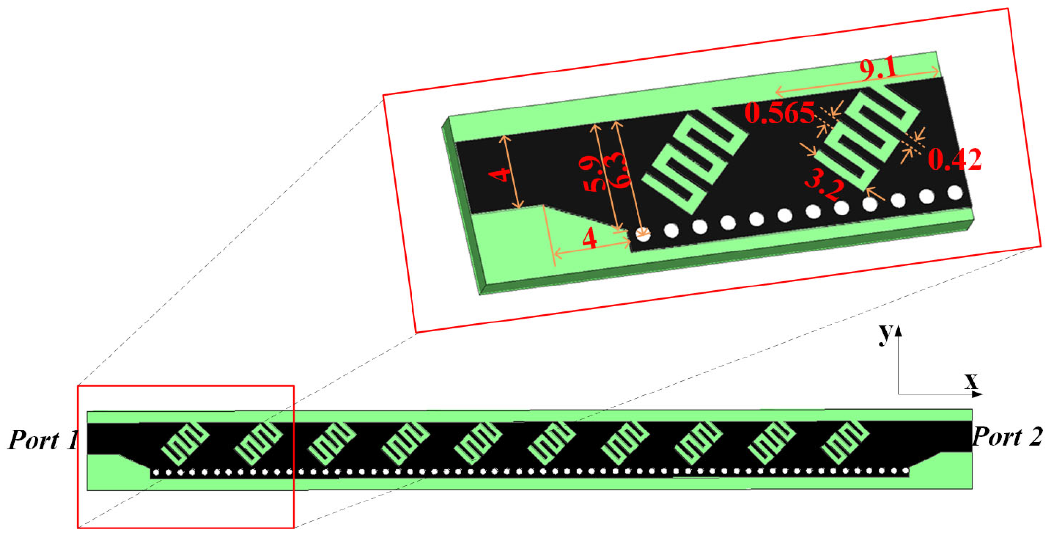
2.1. The Designed Antenna Structure
The proposed polarization-flexible and frequency-scanning antenna is depicted in Figure 2. It consists of four microstrip feed lines, a 3 dB directional coupler, two microstrip slot antennas, and metallic vias forming an SIW and two HMSIWs. Each slot antenna is made of ten interdigital slots inclined at −45 or +45 to the propagation direction (the x-direction), generating LW radiation. The 3 dB directional coupler is made with SIW, which feeds two half-mode SIWs (HMSIWs) underneath the interdigital slots. The complete structure was built on the common substrate of Rogers 5880 with a thickness of 1.575 mm, a permittivity of 2.2, and a loss tangent of 0.001. The vias underneath the interdigital slots have a diameter of 0.8 mm and a center-to-center spacing of around 1.5 mm, forming the HMSIWs. The vias underneath the coupler have a diameter of 0.5 mm and a center-to-center spacing of 0.8 mm, forming the SIW.
Figure 2.
The three-dimensional view of the proposed polarization-flexible and frequency-scanning antenna.
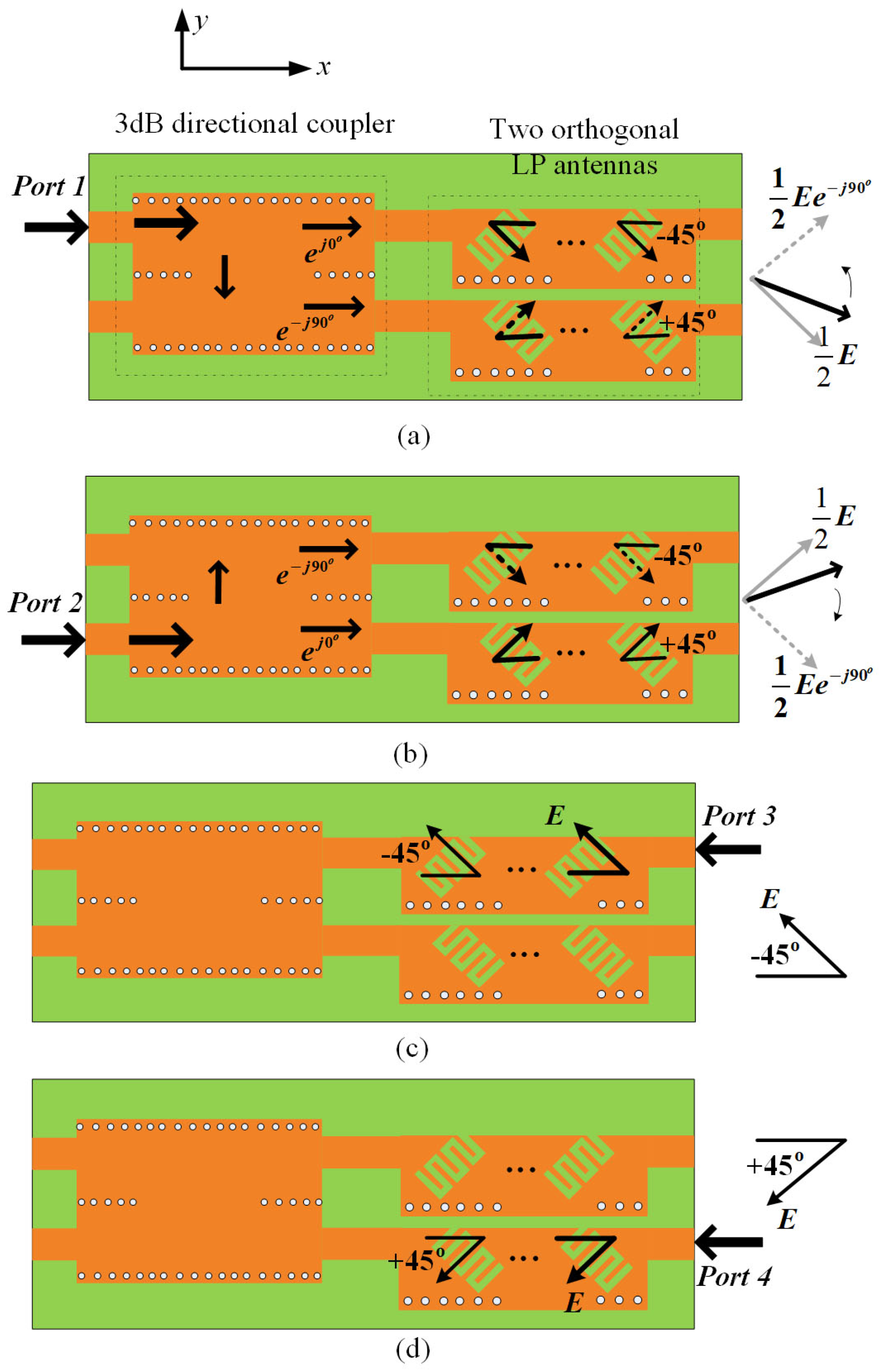
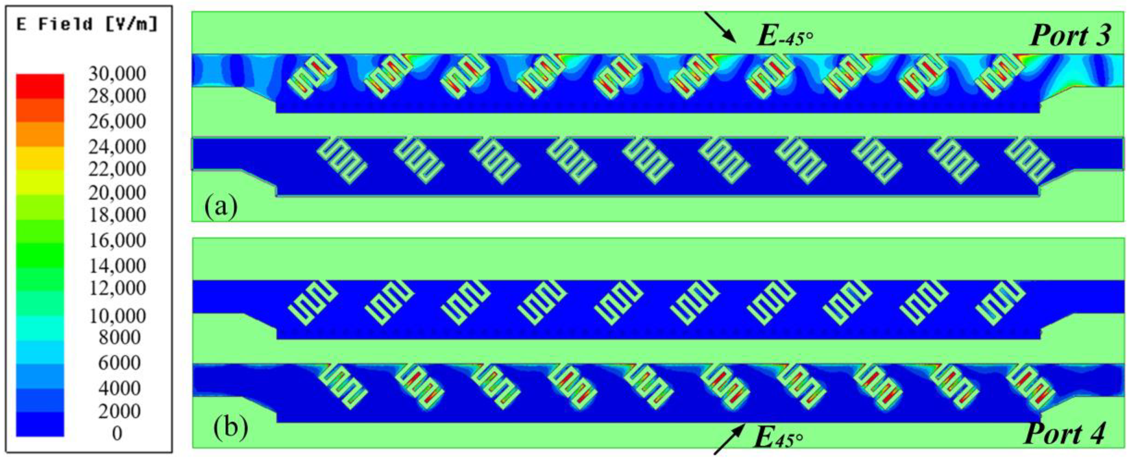
2.2. Operational Principle
The operation of the proposed antenna is described as follows. The LW radiation is generated by interdigital slots fed through the HMSIWs. Because the two interdigital slot antennas are oriented at −45 or +45 to the x-direction, respectively (as shown in Figure 3), they radiate in the directions that are 90 apart spatially. As a result, by configuring excitations at ports in different ways, different polarizations can be achieved.
Figure 3.
The four excitation and polarization scenarios: (a) RHLP (shaded arrows represent the radiation generated by the slot antenna individually), (b) LHCP (shaded arrows represent the radiation generated by the slot antenna individually), (c) −45 LP, and (d) +45 LP.
Figure 3 shows the four scenarios of polarization: when Port 1 or Port 2 is excited, the fed fields (or currents on the strips) will flow as shown in Figure 3a,b, leading to right-hand circular polarization (RHCP) and left-hand circular polarization (LHCP), respectively. When Port 3 or Port 4 is exited, only one of the interdigital slot antennas is excited, and linear polarization (LP) is generated, as shown in Figure 3c,d.
3. The Key Design Considerations
3.1. Dimensions of the SIW and HMSIW
To ensure that the SIW for the 3 dB directional coupler behaves similarly to the conventional rectangular waveguide, two conditions must be met [28]:
where s is the space between two vias, d is the diameter of the vias, and w is the width of the SIW. w can be decided first based on the operating frequency range [29]. Then, d and s can be decided through conditions (1) and (2). The use of the HMSIW structure to feed the interdigital slot antennas can lead to size reduction by half compared to the SIW. It also allows the convenient transition from the 3 dB SIW coupler to the two HMSIWs (that feed the two interdigital slot antennas) without increasing the transition size. For the HMSIWs, the width, w, was set to be half of the SIW structure. The rest of the physical dimensions were chosen to be the same as those of the SIW.
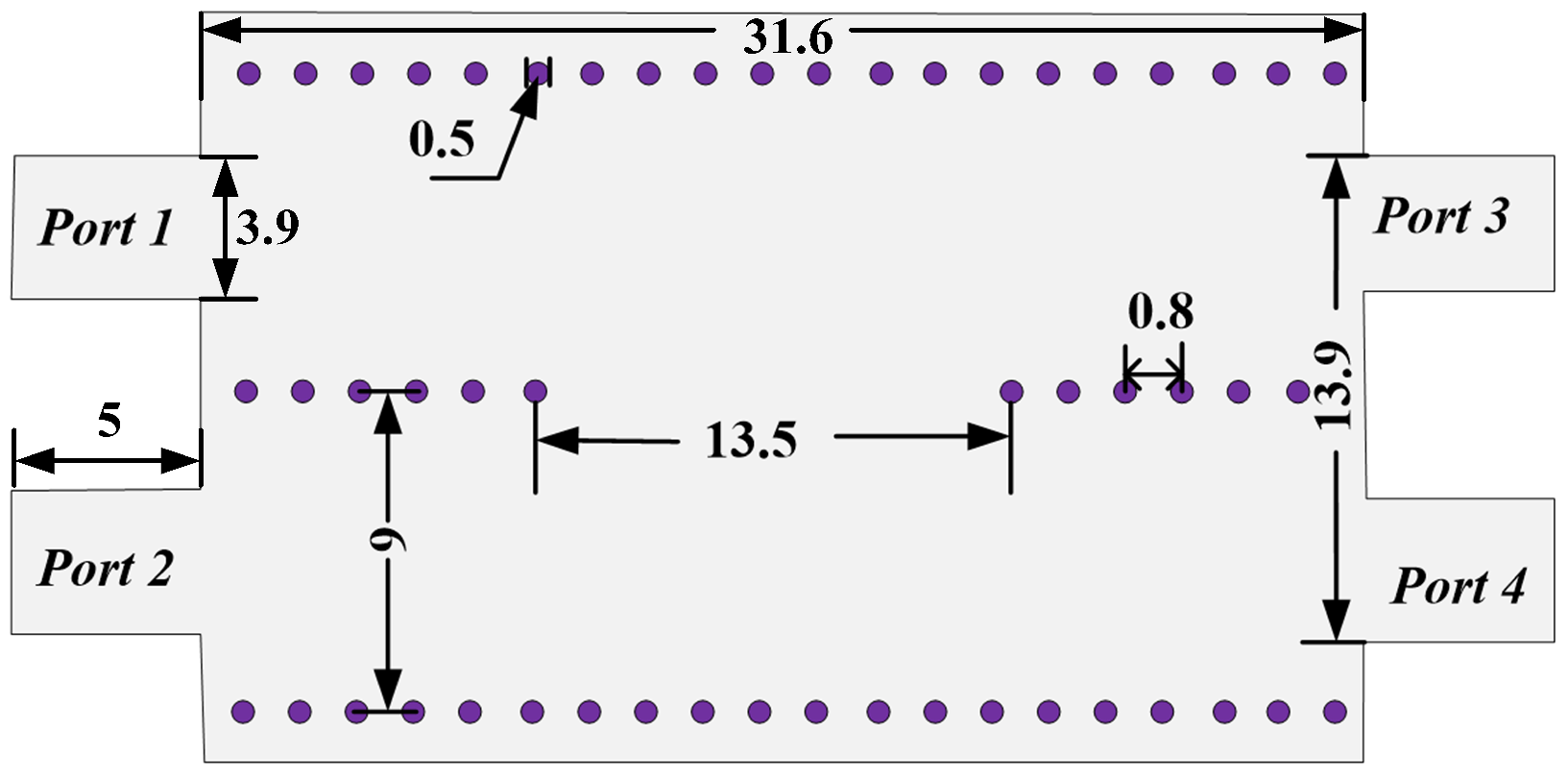
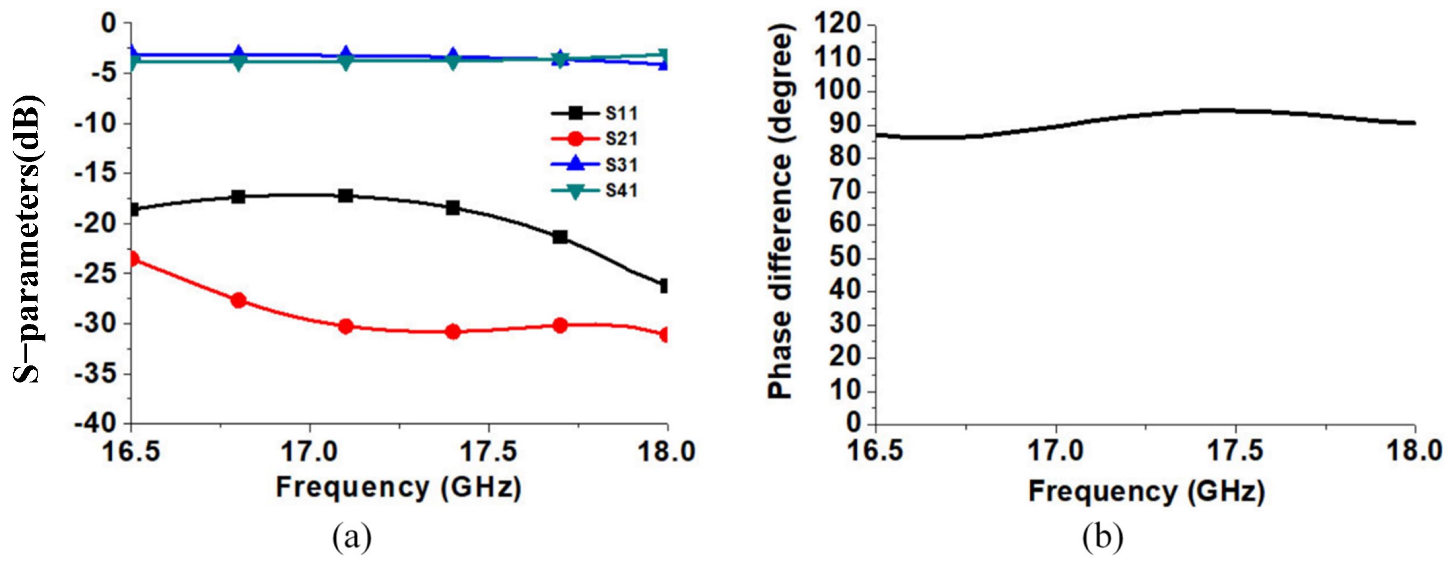
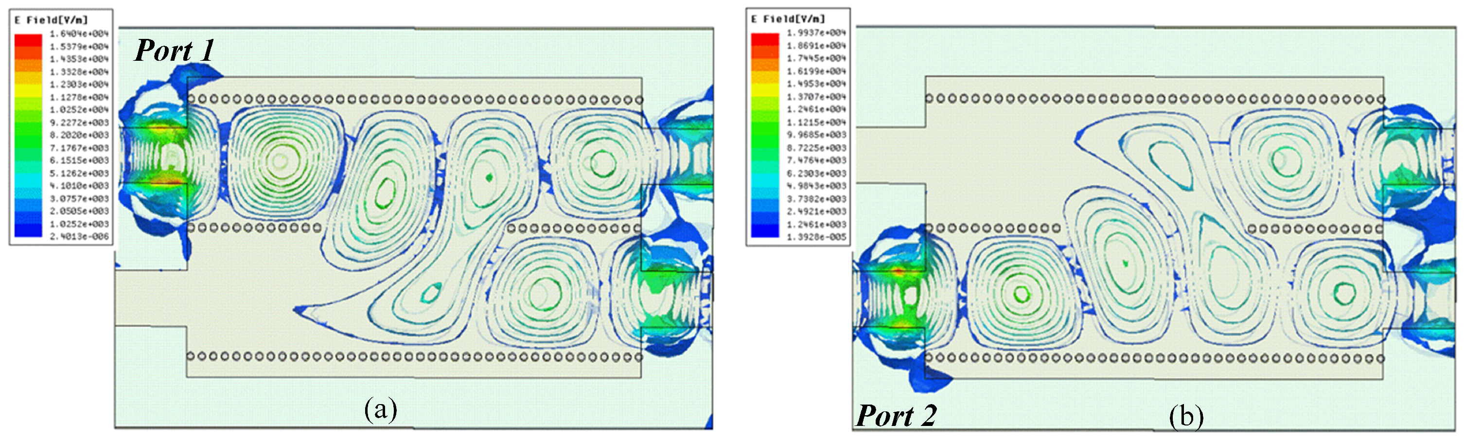
3.2. The 3 dB SIW Directional Coupler
The 3 dB directional coupler provides 90 in phase difference for the fields (or currents) fed to the two interdigital slot antennas. The detailed design of the coupler can be found in [30]. In our design, we optimized the geometrical configuration and parameters of the coupler for a frequency band of 16.5GHz–18GHz. The final results of the dimensions are shown in Figure 4.
Figure 4.
The optimized dimensions for the proposed 3 dB SIW coupler (unit: mm).
The simulated scattering parameters of the coupler are presented in Figure 5. As can be seen, within the band of 16.5 GHz to 18 GHz, the simulated reflection coefficient |S11| of the coupler is below −15 dB, the isolation |S21| is better than −20 dB, and the transmission coefficients |S31| and |S41| are −3.5 dB ± 0.5 dB. The simulated phase difference of the two output ports is 90 ± 4.5.
Figure 5.
(a) Simulated S–parameters of the 3 dB SIW coupler and (b) simulated phase difference between two output ports of the 3 dB SIW coupler.
As shown in Figure 6a, when Port 1 is excited, the signal of Port 4 is coupled and transmitted through the coupling port, so the phase of the output signal of Port 4 lags behind that of Port 3 by 90. In addition, since the coupler is composed of two symmetrical SIWs, the amplitudes of the output signals at Port 3 and Port 4 are equal. Similarly, as shown in Figure 6b, when Port 2 is excited, the signal amplitudes of Port 3 and Port 4 are equal and the phase of Port 3 lags behind that of Port 4 by 90.
Figure 6.
The electric field distribution of the coupler under different port excitations (a,b).
3.3. The Interdigital Slot Antennas
Each slot antenna has ten interdigital LW slots, equivalent to a 10-element mini array whose radiation beam directions may change with frequency due to the distance change relative to wavelength (or frequency). In other words, by scanning the operating frequency, the radiation direction of the LW antennas is changed, resulting in the beam scanning of the whole antenna.
The geometry of the interdigital slot antennas with optimized parameters is shown in Figure 7. The simulated scattering parameters of the slot antenna are presented in Figure 8a. The reflection coefficient |S11| and insertion loss of the slot antenna |S21| are below −10 dB from 16.5 GHz to 18 GHz. Figure 8b shows the simulated gains at different frequencies in the x–z plane (E-plane), including those for co-polarization and cross-polarization. The theta is defined as the angle between the line connecting the coordinate origin to point P in space and the radiator’s normal (z-axis, as shown in Figure 2) when the origin coincides with the geometric center of the antenna. The simulated gains are 10.84, 13.52, and 12.78 dBi, and the beam directions are 44, 36, and 20 at 17, 17.3, and 17.6 GHz, respectively.
Figure 7.
The optimized dimensions of the proposed interdigital slot antenna (unit: mm).
Figure 8.
(a) The S–parameters of the −45 LP antenna, and (b) simulated gain for the −45 LP antenna in the E–plane at the 17 GHz, 17.3 GHz, and 17.6 GHz, respectively.
3.4. The Positioning of the Two Interdigital Slot Antennas
The two interdigital slot antennas are shown in Figure 9. The electric field distributions of antennae 1 and 2 are shown in Figure 10 under Port 3 or Port 4 excitation, respectively. The slot antenna 1 with a −45 inclination can generate a −45 LP mode, and antenna 2 with a 45 inclination can generate a +45 LP. A CP can be generated when the two slot antennas are excited with equal amplitudes but a 90 phase difference. Based on this principle, a pair of interdigital slot antennas are combined with a 3 dB SIW directional coupler. When Port 1 is excited, the RHCP is generated. When Port 2 is excited, the LHCP is generated.
Figure 9.
The structure of the two interdigital slot antennas; an offset is added to enhance the axial ratio of the CP generated.
Figure 10.
The electric field distribution under (a) Port 3 or (b) Port 4 excitation, respectively.
To have a good axial ratio (AR) of the CP, the spatial offset between the two slot antennas, as shown in Figure 9, was acquired. In other words, this offset is used to optimize AR and gain for the frequency band of interest.
The simulated gain and axial ratio of the two slot antennas at 17.3 GHz with different spatial offsets are shown in Figure 11. Figure 11a reveals that the undesired cross-polarization level increases when the offset is larger or smaller than 3.6 mm. Figure 11b shows that the axial ratio is much affected by the offset, and the ratio achieves its best value when the offset is 3.6 mm. As a result, the offset was taken to be 3.6 mm in this design.
Figure 11.
Simulated (a) gain and (b) axial ratio for the two antennas with different offsets at 17.3 GHz in the x–z plane.
To increase the isolation between the two slot antennas, it is desirable to have the distance between them be as large as possible. Since the distance between Port 1 and Port 2 of the coupler is 13.9 mm (see Figure 4), the largest distance between them can only be 13.9 mm, which was taken in this design.
Figure 12a shows the simulated RHCP gain in the x–z plane at 17 GHz, 17.3 GHz, and 17.6 GHz, respectively. The gains are above 10 dBi. Figure 12b shows the simulated axial ratio at the three frequencies. The axial ratio in the main beam direction is always below 3 dB.
Figure 12.
(a) Simulated gain and (b) simulated axial ratio of the proposed antennas that generate RHCP in the x–z plane at 17 GHz, 17.3 GHz, and 17.6 GHz, respectively.
The simulated radiation efficiency of the designed antenna is shown in Figure 13. In the frequency range of 16.5 GHz–18 GHz, a high radiation efficiency is achieved under four polarization states.
Figure 13.
The radiation efficiency of the designed antenna.
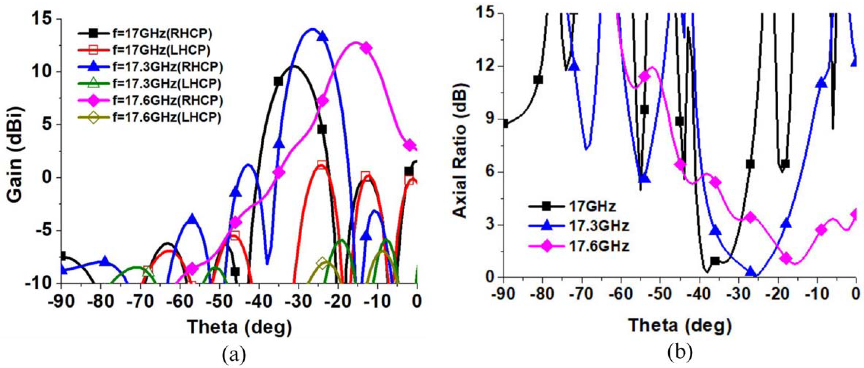
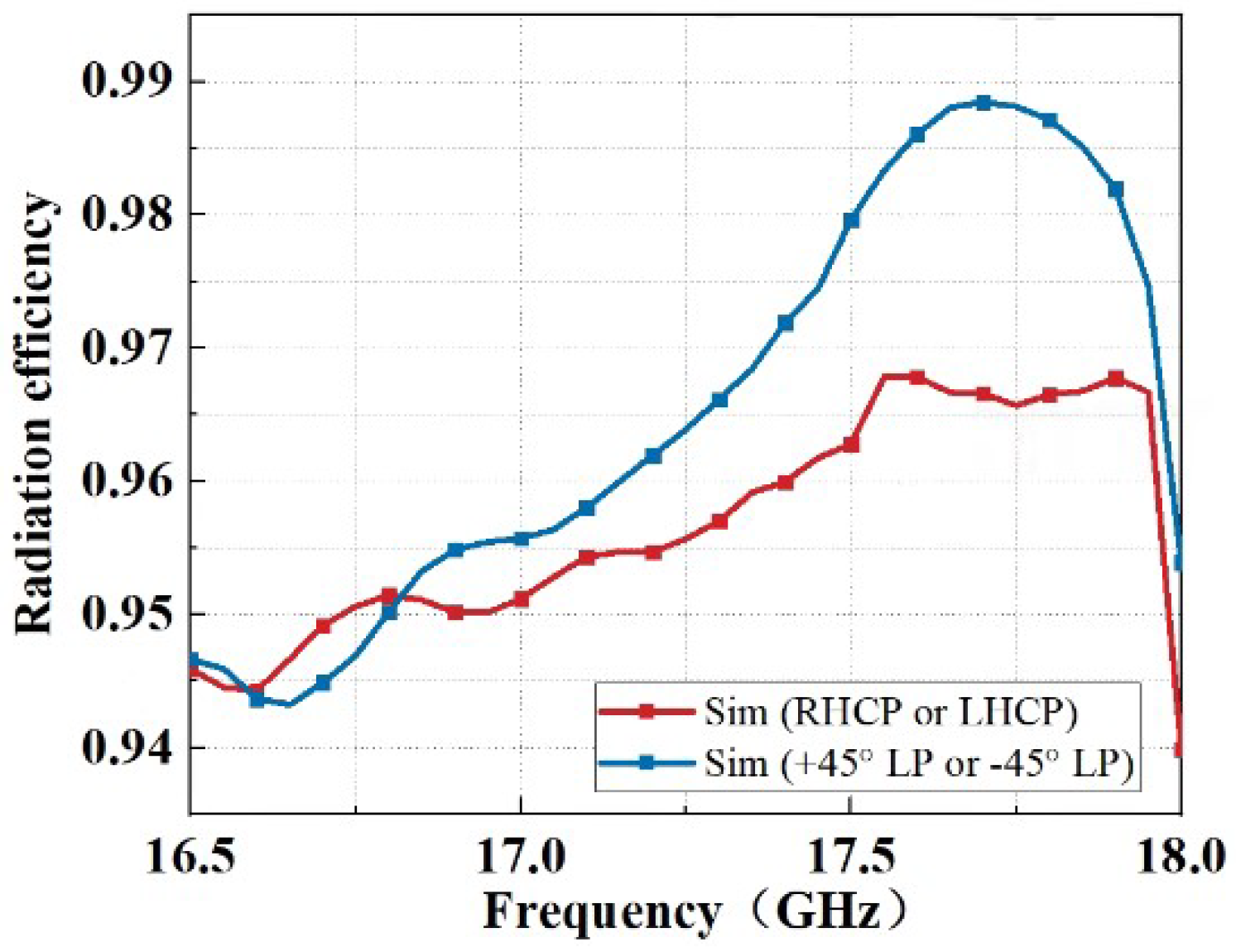
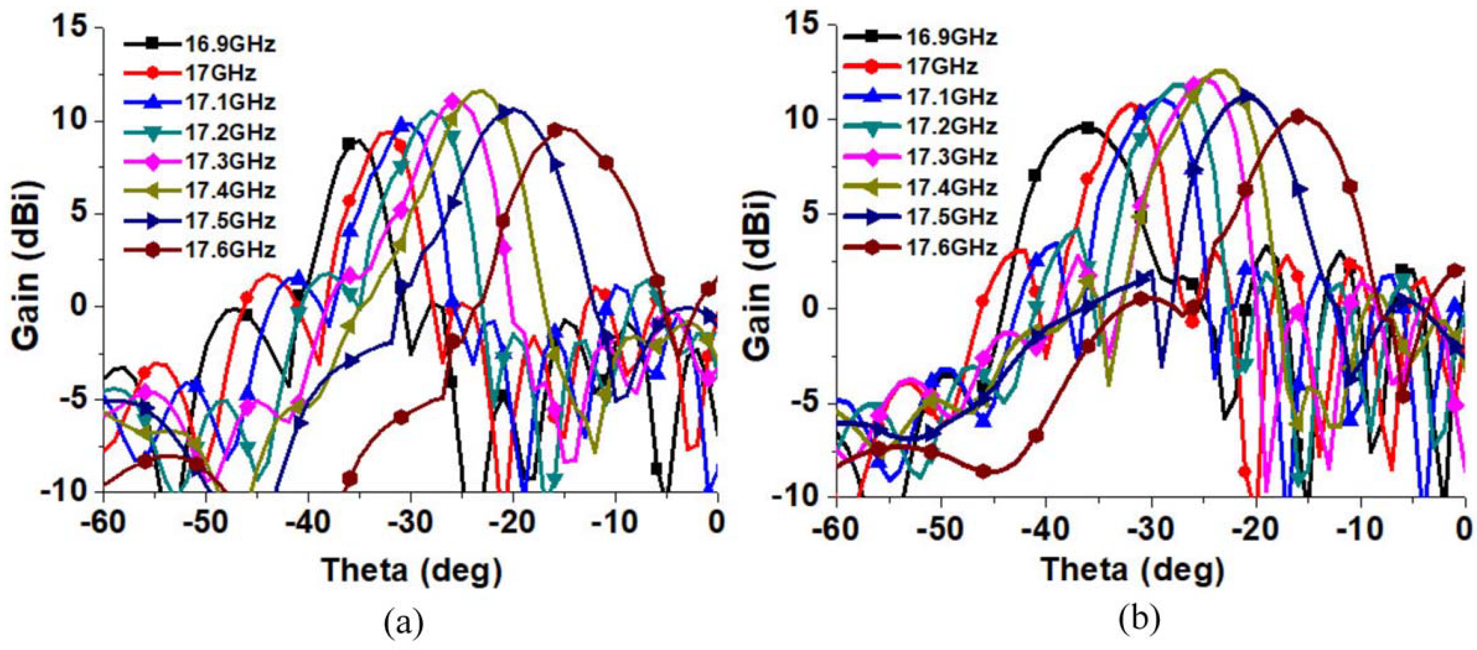
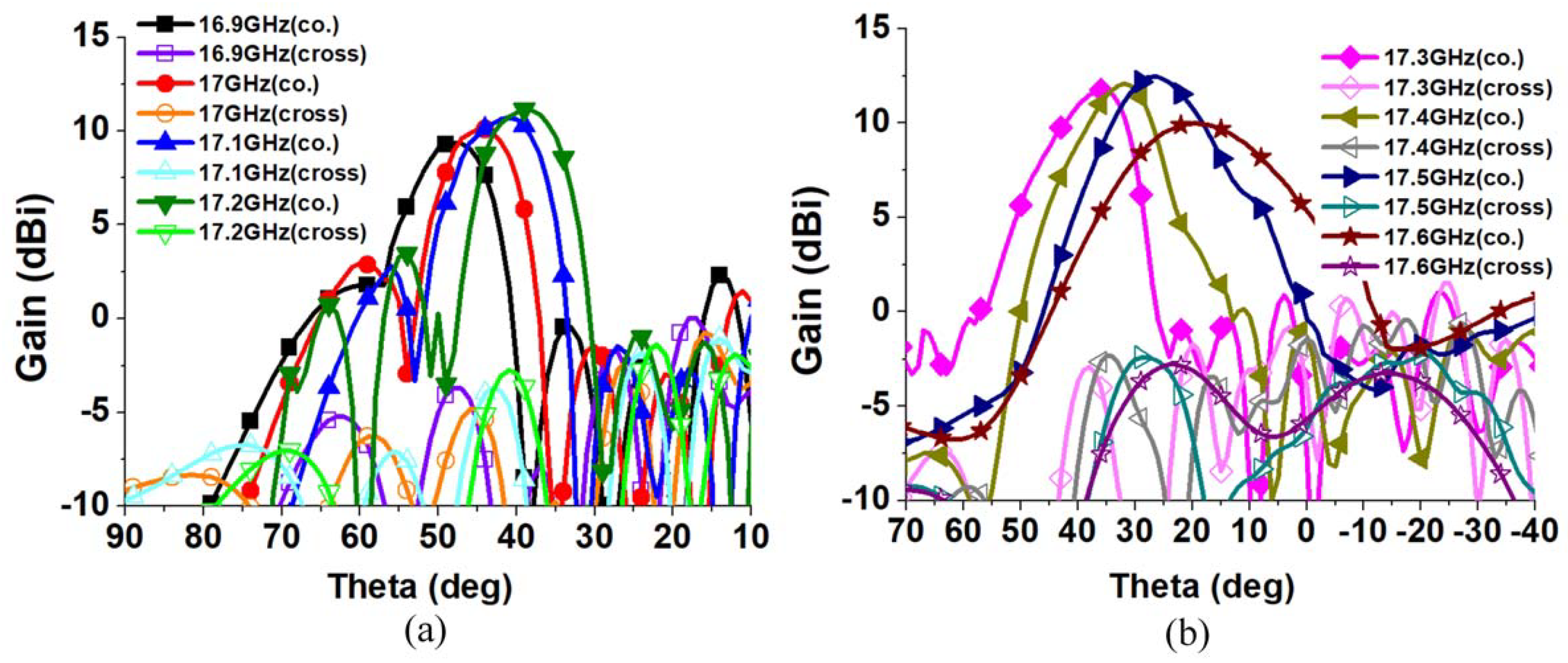
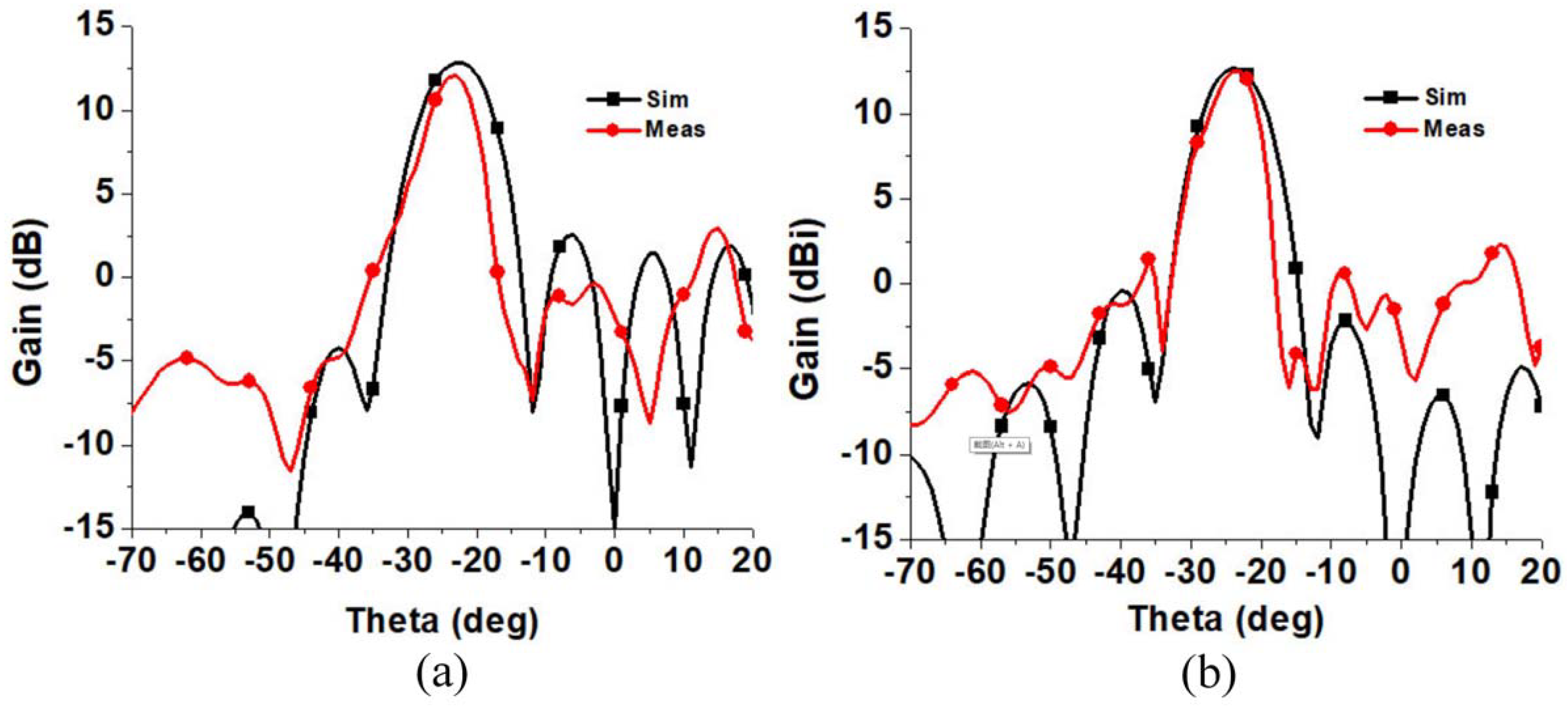
4. Experimental Results
The proposed antenna was fabricated and tested. Figure 14 shows the photo of the fabricated antenna. The scattering parameters were measured using the Agilent vector network analyzer N5234A. The measurement results are shown in Figure 15. Figure 15a shows the measured and simulated S-parameter results when Port 1 is excited, and the other ports are terminated with a 50 matching load. Similarly, Figure 15b–d are the results when Ports 2, 3, and 4 are excited, respectively. Two aspects mainly cause the differences between the simulation and the measurements. First, the SMA connector was not included in the simulation. During the measurement, the introduction and welding of SMA connectors affected the impedance matching of the antenna ports and caused the loss. Second, some errors in the fabrication resulted in a change in the S-parameter results, which also decreased the measured gain.
Figure 14.
Photograph of the fabricated antenna.
Figure 15.
Measured and simulated scattering parameters of the proposed antenna when excited at (a) Port 1, (b) Port 2, (c) Port 3, and (d) Port 4, respectively.
The proposed antenna with polarization flexibility and frequency scanning was measured in an anechoic chamber using the setup shown in Figure 16. A standard gain LP horn antenna as the transmitter was rotated at a given angle by varying the polarization modes. The standard gain antenna was measured first for calibration. The measured antenna as a receiver was rotated from −180 to 180, and the receiving power level was detected and recorded at the corresponding port.
Figure 16.
Measurement setup used to test the proposed antenna.
The measured gains of RHCP or LHCP are plotted in Figure 17a,b when Port 1 or 2 is excited. Table 1 summarizes the key measurement and simulation data of RHCP and LHCP. The proposed antenna can cover the angle range of (−38.5, −10) for RHCP and (−40.5, −11.5) for LHCP with the 3 dB beam-width in the x–z plane. The axial ratio of the beam directions is always below 2 dB.
Figure 17.
(a) The measured RHCP gain and (b) the measured LHCP gain of the proposed antenna in the x–z plane.
Table 1.
Measured and simulated results of CP.
The reduced gain mainly introduced the mismatch between the experimental and the simulated results. Three reasons were conjectured for the measured gain’s being lower than the simulated gain: first, there was loss from the SMA connector that was not included in the simulation and some errors in the fabrication results in a reduced gain; second, the conductor and dielectric loss in the fabricated antenna were probably higher than in the simulated one; third, the chamber for measuring the antenna was not ideally large enough, which would lead to some inaccuracy for the gain measurement.
Figure 18 and Figure 19 present the co-pol and cross-pol gains when Port 3 or Port 4 is excited. Table 2 summarizes the key measurement and simulation data of −45 LP and 45 LP. The antenna can cover the angular range of (7, 54.5) in the x–z plane when Port 3 is excited and (6, 53) when Port 4 is excited.
Figure 18.
The measured co–pol and cross–pol gain of the proposed antenna when excited at Port 3 with the frequency range of (a) 16.9 GHz to 17.2 GHz and (b) 17.3 GHz to 17.6 GHz in the x–z plane.
Figure 19.
The measured co–pol and cross–pol gains of the proposed antenna when excited at Port 4 for the frequency range of (a) 16.9 GHz–17.2 GHz and (b) 17.3 GHz–17.6 GHz in the x–z plane.
Table 2.
Measured and simulated results of LP.
Comparisons between the measured and simulated results of the proposed antenna at 17.4 GHz are shown in Figure 20 and Figure 21. As can be seen, the measurements presented somewhat lower values in gain and beam-width. This could be attributed to the fabrication errors, deviations in the real material parameters from the simulated ones, and the ideal geometry setting in simulation. However, overall, the experimental results corroborated sufficiently the simulation ones. As can be seen in Table 3, the proposed antenna had more flexible polarization and a higher gain.
Figure 20.
(a) The measured and simulated gains in the x–z plane when RHCP is generated; (b) the measured and simulated gains in the x–z plane when LHCP is generated.
Figure 21.
(a) The measured and simulated co–pol and cross–pol gains of the proposed antenna in the E–plane when excited at Port 3 and LP is generated; (b) the measured and simulated co–pol and cross–pol gains of the proposed antenna in the E–plane when excited at Port 4 and LP is generated.
Table 3.
The comparison between the proposed design and previous antennas.
5. Conclusions
To solve the problem that many antennas are needed for the communication, navigation, and safe driving functions of automobiles, a frequency-scanning antenna using an HMSIW leak-wave structure for polarization-agile applications is implemented in this paper. Depending on the excitations, it generates different polarization states. The antenna can generate continuous scanning LP beams covering the angular range of 47.5 (the difference between 7 and 54.5) and CP beams with good AR covering in the angular range of 28.5 (the difference between −38.5 and −10). With an increase in the frequency, the beam direction moves towards the broadside. The antenna has good performance in return loss under four polarization states. The proposed antenna can be used as a multifunctional antenna for vehicular applications and chip-scaled SAR systems.
Author Contributions
A.C.: conceptualization and methodology; X.F.: investigation and writing—review and editing; W.J.: visualization, validation, and writing—original draft; K.A.: formal analysis. All authors have read and agreed to the published version of the manuscript.
Funding
This work was supported in part by the Major Basic Research on Equipment under Grant 514010403-302-2, in part by the Domain Foundation of Equipment Advance Research under Grant 61402090204, and in part by the Key Laboratory Foundation of Equipment Pre-research under Grant 61424020108.
Data Availability Statement
Not applicable.
Conflicts of Interest
The authors declare no conflict of interest.
References
- Ge, X.; Cheng, H.; Mao, G.; Yang, Y.; Tu, S. Vehicular Communications for 5G Cooperative Small-Cell Networks. IEEE Trans. Veh. Technol. 2016, 65, 7882–7894. [Google Scholar] [CrossRef] [Green Version]
- Ge, L.; Gao, S.; Li, Y.; Qin, W.; Wang, J. A Low-Profile Dual-Band Antenna With Different Polarization and Radiation Properties Over Two Bands for Vehicular Communications. IEEE Trans. Veh. Technol. 2019, 68, 1004–1008. [Google Scholar] [CrossRef]
- Dudek, M.; Nasr, I.; Bozsik, G.; Hamouda, M.; Kissinger, D.; Fischer, G. System Analysis of a Phased-Array Radar Applying Adaptive Beam-Control for Future Automotive Safety Applications. IEEE Trans. Veh. Technol. 2015, 64, 34–47. [Google Scholar] [CrossRef]
- Jeon, S.Y.; Ka, M.H.; Shin, S.; Kim, M.; Kim, S.; Kim, S.; Kim, J.; Dewantari, A.; Kim, J.; Chung, H. W-Band MIMO FMCW Radar System With Simultaneous Transmission of Orthogonal Waveforms for High-Resolution Imaging. IEEE Trans. Microw. Theory Tech. 2018, 66, 5051–5064. [Google Scholar] [CrossRef]
- Brunetti, G.; Armenise, M.; Ciminelli, C. Chip-Scaled Ka-Band Photonic Linearly Chirped Microwave Waveform Generator. Front. Phys. 2022, 10, 785650. [Google Scholar] [CrossRef]
- Khilo, A.; Spector, S.; Grein, M.; Nejadmalayeri, A.; Holzwarth, C. Photonic ADC: Overcoming the bottleneck of electronic jitter. Opt. Express 2012, 20, 4454–4469. [Google Scholar] [CrossRef]
- Xiao, X.; Li, S.; Chen, B.; Yang, X.; Wu, D.; Xue, X.; Zheng, X.; Zhou, B. A microwave photonics-based inverse synthetic aperture radar system. In Proceedings of the 2017 Conference on Lasers and Electro-Optics (CLEO), San Jose, CA, USA, 14–19 May 2017; pp. 1–2. [Google Scholar]
- Ishimaru, A.; Tuan, H. Frequency scanning antennas. In 1958 IRE International Convention Record; IEEE: Piscataway, NJ, USA, 1961; pp. 101–109. [Google Scholar]
- Mohsen, M.; Isa, M.; Isa, A.; Abdulhameed, M.; Attiah, M. Achieving Fixed-Frequency Beam Scanning With a Microstrip Leaky-Wave Antenna Using Double-Gap Capacitor Technique. IEEE Antennas Wirel. Propag. Lett. 2019, 18, 1502–1506. [Google Scholar] [CrossRef]
- Rahmani, M.; Deslandes, D. Backward to Forward Scanning Periodic Leaky-Wave Antenna With Wide Scanning Range. IEEE Trans. Antennas Propag. 2017, 65, 3326–3335. [Google Scholar] [CrossRef]
- Wu, G.; Wang, G.; Liang, J.; Gao, X. Dual-band periodic beam scanning antenna using eighth mode substrate integrated waveguide based metamaterial transmission line. J. Phys. D-Appl. Phys. 2017, 50, 1–8. [Google Scholar] [CrossRef]
- Xie, S.; Li, J.; Deng, G.; Feng, J.; Xiao, S. A Wide-Angle Scanning Leaky-Wave Antenna Based on a Composite Right/Left-Handed Transmission Line. Appl. Sci. 2020, 10, 1927. [Google Scholar] [CrossRef] [Green Version]
- Li, Y.; Zhang, Z.; Zheng, J.; Feng, Z. Channel capacity study of polarization reconfigurable slot antenna for indoor MIMO system. Microw. Opt. Technol. Lett. 2011, 53, 1209–1213. [Google Scholar] [CrossRef]
- Kovitz, J.; Rajagopalan, H.; Rahmat-Samii, Y. Design and Implementation of Broadband MEMS RHCP/LHCP Reconfigurable Arrays Using Rotated E-Shaped Patch Elements. IEEE Trans. Antennas Propag. 2015, 63, 2497–2507. [Google Scholar] [CrossRef]
- Grau, A.; Romeu, J.; Lee, M.; Blanch, S.; Jofre, L.; De Flaviis, F. A Dual-Linearly-Polarized MEMS-Reconfigurable Antenna for Narrowband MIMO Communication Systems. IEEE Trans. Antennas Propag. 2010, 58, 4–17. [Google Scholar] [CrossRef]
- Fartookzadeh, M.; Mohseni Armaki, S. Circular feeding network for circular polarization reconfigurable antennas. Electron. Lett. 2019, 55, 677–679. [Google Scholar] [CrossRef]
- Yang, L.; Yang, L.; Zhu, Y.; Yoshitomi, K.; Kanaya, H. Polarization reconfigurable slot antenna for 5.8 GHz wireless applications. Aeu-Int. J. Electron. Commun. 2019, 101, 27–32. [Google Scholar] [CrossRef]
- Seongmin, P.; Youngje, S. A circular polarized microstrip antenna with an arrow-shaped slotted ground. Microw. Opt. Technol. Lett. 2012, 54, 271–273. [Google Scholar]
- Shu, C.; Wang, J.; Hu, S.; Yao, Y.; Yu, J.; Alfadhl, Y.; Chen, X. A Wideband Dual-Circular-Polarization Horn Antenna for mmWave Wireless Communications. IEEE Antennas Wirel. Propag. Lett. 2019, 18, 1726–1730. [Google Scholar] [CrossRef]
- McMichael, I. A Mechanically Reconfigurable Patch Antenna With Polarization Diversity. IEEE Antennas Wirel. Propag. Lett. 2018, 17, 1186–1189. [Google Scholar] [CrossRef]
- Karamzadeh, S.; Rafii, V.; Saygin, H.; Kartal, M. Polarisation diversity cavity back reconfigurable array antenna for C-band application. IET Microw. Antennas Propag. 2016, 10, 955–960. [Google Scholar] [CrossRef]
- Lim, J.; Back, G.; Yun, T. Polarization-diversity cross-shaped patch antenna for satellite-DMB systems. ETRI J. 2010, 32, 312–318. [Google Scholar] [CrossRef]
- Suntives, A.; Hum, S. A Fixed-Frequency Beam-Steerable Half-Mode Substrate Integrated Waveguide Leaky-Wave Antenna. IEEE Trans. Antennas Propag. 2012, 60, 2540–2544. [Google Scholar] [CrossRef]
- Liu, J.; Jackson, D.; Long, Y. Substrate Integrated Waveguide (SIW) Leaky-Wave Antenna With Transverse Slots. IEEE Trans. Antennas Propag. 2012, 60, 20–29. [Google Scholar] [CrossRef]
- Dong, Y.; Itoh, T. Composite Right/Left-Handed Substrate Integrated Waveguide and Half Mode Substrate Integrated Waveguide Leaky-Wave Structures. IEEE Trans. Antennas Propag. 2011, 59, 767–775. [Google Scholar] [CrossRef]
- Pourghorban Saghati, A.; Mirsalehi, M.; Neshati, M. A HMSIW Circularly Polarized Leaky-Wave Antenna With Backward, Broadside, and Forward Radiation. IEEE Antennas Wirel. Propag. Lett. 2014, 13, 451–454. [Google Scholar] [CrossRef]
- Dong, Y.; Itoh, T. Substrate Integrated Composite Right-/Left-Handed Leaky-Wave Structure for Polarization-Flexible Antenna Application. IEEE Trans. Antennas Propag. 2012, 60, 760–771. [Google Scholar] [CrossRef]
- Xu, F.; Wu, K. Guided-wave and leakage characteristics of substrate integrated waveguide. IEEE Trans. Microw. Theory Tech. 2005, 53, 66–73. [Google Scholar]
- Cassivi, Y.; Perregrini, L.; Arcioni, P.; Bressan, M.; Wu, K.; Conciauro, G. Dispersion characteristics of substrate integrated rectangular waveguide. IEEE Microw. Wirel. Compon. Lett. 2002, 12, 333–335. [Google Scholar] [CrossRef]
- Liu, B.; Hong, W.; Wang, Y.; Lai, Q.; Wu, K. Half Mode Substrate Integrated Waveguide (HMSIW) 3-dB Coupler. IEEE Microw. Wirel. Compon. Lett. 2007, 17, 22–24. [Google Scholar] [CrossRef]
Publisher’s Note: MDPI stays neutral with regard to jurisdictional claims in published maps and institutional affiliations. |
© 2022 by the authors. Licensee MDPI, Basel, Switzerland. This article is an open access article distributed under the terms and conditions of the Creative Commons Attribution (CC BY) license (https://creativecommons.org/licenses/by/4.0/).


