Review

Review on Haptic Assistive Driving Systems Based on Drivers’ Steering-Wheel Operating Behaviour

by
Simplice Igor Noubissie Tientcheu
,
Shengzhi Du
* and
Karim Djouani
*
Electrical Engineering Department, Tshwane University of Technology, Pretoria 0001, South Africa
*
Authors to whom correspondence should be addressed.
Electronics 2022, 11(13), 2102; https://doi.org/10.3390/electronics11132102
Submission received: 1 June 2022 / Revised: 15 June 2022 / Accepted: 21 June 2022 / Published: 5 July 2022
(This article belongs to the Special Issue Feature Papers in Systems & Control Engineering)

Abstract

:
With the availability of modern assistive techniques, ambient intelligence, and the Internet of Things (IoT), various innovative assistive environments have been developed, such as driving assistance systems (DAS), where the human driver can be provided with physical and emotional assistance. In this human–machine collaboration system, haptic interaction interfaces are commonly employed because they provide drivers with a more manageable way to interact with other components. From the view of control system theory, this is a typical closed-loop feedback control system with a human in the loop. To make such a system work effectively, both the driving behaviour factors, and the electrical–mechanical components should be considered. However, the main challenge is how to deal with the high degree of uncertainties in human behaviour. This paper aims to provide an insightful overview of the relevant work. The impact of various types of haptic assistive driving systems (haptic guidance and warning systems) on driving behaviour performance is discussed and evaluated. In addition, various driving behaviour modelling systems are extensively investigated. Furthermore, the state-of-the-art driving behaviour controllers are analysed and discussed in driver–vehicle–road systems, with potential improvements and drawbacks addressed. Finally, a prospective approach is recommended to design a robust model-free controller that accounts for uncertainties and individual differences in driving styles in a haptic assistive driving system. The outcome indicated that the haptic feedback system applied to the drivers enhanced their driving performance, lowered their response time, and reduced their mental workload compared to a system with auditory or visual signals or without any haptic system, despite some annoyances and system conflicts. The driving behaviour modelling techniques and the driving behaviour control with a haptic feedback system have shown good matching and improved the steering wheel’s base operation performance. However, mathematical principles, a statistical approach, and the lack of consideration of the individual differences in the driver–vehicle–road system make the modelling and the controller less robust and inefficient for different driving styles.

1. Introduction

Human cognitive behaviours can affect car driving performance, such as perception (eyes, skin, muscle), knowledge (training, experience), and decision-making capacity. Many car accidents are caused by driver omissions, and factors such as workload and fatigue can lead to significant driver failures [1,2]; 70% of road accidents are a consequence of driver inattention [3]. Several studies have been suggested to enhance car lateral control [4]. Results of a survey on car accidents indicate that the lane departure avoidance approach could probably prevent 31% of fatal car crashes [5].
Fenton previously initiated a haptic feedback system to assist drivers [6]. It was found that implementing an assistive system into a car driving operation leads to lowering the driver workload [7]. A centre line or lane-keeping achievement is one of the significant measures of driver performance. De Groot et al. [8] proposed a system that assists the driver in keeping the car in the lane’s centre when it exceeds a threshold by providing the operator with seat vibrations. Haptic warning feedback based on vibration information was set on the seat belt to alert the driver when he is fatigued [9]. However, haptic warning feedback has limitations, such as fake alarms, inattention due to car vibrations, uneven driveways, and lower performance in lane-keeping. In addition, an extreme vibration stimulus may generate irritation to the driver [10].
To overcome the haptic warning feedback drawbacks, continuous haptic steering guidance has been developed, providing a feedback torque relevant to the lane deviation to help the driver stay in the lane [11]. Furthermore, some studies have shown that a continuous haptic assistive system appeared to lower the driver workload [12] and enhance the target trajectory achievement [13]. In this approach, the driving duty operates concurrently by the driver and the system via a shared control [14]. In this system, the continuous haptic guidance captures the driver’s action and feeds back the corresponding force as a haptic stimulus.
However, some studies have reported that the functionality of continuous haptic guidance steering or haptic share control has a drawback when the driver’s intention does not match the steering haptic guidance torque [11]. In addition, the after-effect problem occurred when a driver expected force feedback (torque), but the system provided a null field. To reduce the system’s after-effects, and the fake alarms, Petrmeijer et al. [15] introduced bandwidth guidance to the existing haptic guidance to assist the driver at a specific range.
However, haptic guidance for lane-keeping assistance systems (LKASs) is developed only on the vehicle–road model. Therefore, the human behaviour model is not considered as a part of the overall system, and this cannot promise the driving performance (stability) nor guarantee that the system will handle significant errors stemming from human uncertainty.
Researchers have conducted several studies to model the driver or operator behaviour to reduce human failure in a system. De Waard used the information processing model to measure different drivers’ mental workload [1]. Bao et al. [16] examined teenagers’ driving behaviour with and without an advanced driver assistance system (ADAS), and they found that teenagers had less pedal control and have shorter time headway when driving at night compared to adults. Zokaei et al. [17] provided research on tracing the physiological response and behavioural performance of a driver, which showed that an emotional conversation via a mobile phone could affect the electroencephalograph (EEG), which, therefore, will cause a decline in the behavioural performance of the driver and the brain. Wang et al. [18] improved driving safety due to fatigue by analysing the impact of fatigue on driving behaviour and proposed a haptic guidance control that considers the driver’s fatigue. Later on, they developed a driving behaviour model based on the weighted fashion that considered the reliance on haptic shared control. In this system, they implemented environment visual feedback from the driver into driving automation [19]. The consideration of the driving behaviour model in the driving–vehicle–road system where the operator’s attitude and the haptic guidance contributed to the steering action have reduced conflict between the driver and the vehicle–road system as detailed in haptic guidance, and the lane-keeping performance has been improved in [20,21].
Drivers have different driving styles, which emanate from distinct perceptions and various levels of knowledge of the task, affecting eye and hand coordination and, therefore, operating performance. This paper evaluates the impact of diverse types of haptic feedback systems (haptic guidance and warning systems) on driving behaviour performance, investigates driver behaviour modelling systems, and explores driving behaviour control in the driver–vehicle–road system with and without a haptic feedback system. A prospective model-free control approach is recommended to compensate for human errors and to stabilise the haptic feedback control system with different driving styles.
The rest of this paper is organised as follows: Section 2 presents the evaluation of haptic feedback performance on driver activities; Section 3 presents different driving behaviour modelling techniques and highlights their advantages and drawbacks; Section 4 presents the driving behaviour controller design; Section 5 presents the prospective direction for developing a robust controller, considering differences in driving behaviour in the haptic guiding system; Section 6 concludes the paper by synthesising all the critical points examined in this paper.

2. Haptic Assistive Driving Systems with Human Operators in the Loop

Lane-keeping (LK) is a complex task that requires a touch (with a steering wheel) and a visual workload. According to Klauer et al. [22], drivers have more than 30 workloads that require visual attention while driving. Many road accidents came from a driver’s wrong manoeuvre due to lack of vision. Therefore, diverse types of haptic feedback (warning and guidance) systems were developed to assist the drivers in staying in their lane by reducing the driver’s workload and improving transport efficiency.

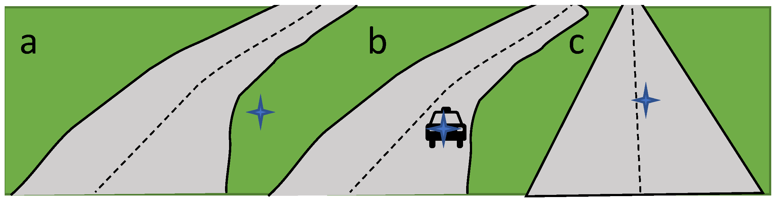
2.1. Haptic Warning Systems

A warning haptic is an assistive system alerting the driver when any threshold is exceeded, meaning when the car is driving away from the lane or the centre line. Klauer et al. [22] analysed the haptic warning in a lane departure warning system (LDWS); the system sent a vibration on the steering wheel to warn the driver when he was out of the lane departure zone. They also analysed the level of recognition of the warning by the driver. The result was that haptic warnings were efficient in unpredicted lane departure, the maximum lateral deviation was reduced to 1.36 m, and the reaction time for unpredicted conditions was shortened [23]. Enriquez et al. [24] added a vibratory haptic on the steering wheel, and this system sent a pulsating sensation to alert the driver when any problem was detected. This work showed that the drivers mean response time was faster when using a car with haptic warnings. The system with three levels of haptic warnings improved the reaction time to 71% feedback. Onimaru et al. [25] developed a warning system with two vibrators mounted on different sides of the steering wheel. The pulsing signal alerted the human driver as soon as the car position moved out of the centre line. Stanley developed haptic warning feedback on the seat belt to warn the driver about a lane departure by providing a vibration on the seat, and the reaction time was reduced from 1.24 to 0.89 s compared to other auditory alerts [26]. In addition, Kurihara et al. [27] constructed a vibrotactile device on the pedal that vibrates to alert the driver to a lane departure, and the reaction time was lower for the system with haptic warnings (1.53 s) compared to the system without a tactile system.
Auditory and visual stimuli are not always effective to provide drivers with good information about their surroundings, so a vibrotactile device was developed by Morrell et al. [28] to convey close surrounding car information to drivers. The experimental results, using a driving simulator, have shown that the driver reaction time deviated from 3.8 s for a haptics warning system to 12.5 s with a system without the vibrotactile device. A haptic warning was mounted on the driver’s belt to assist the driver in dealing with overtaking action [29]. A vibrotactile system was mounted on a driver’s left foot to warn him about any object lying under the vehicle and to allow him to avoid any accident when parking from behind in [30].
Many researchers used binary feedback signals mounted to the driver’s seat belt to alert the driver when the maximum reference was noted or when the car was deviating from the lane to avoid collision [31,32]. Ahtmad et al. [33] mounted a haptic warning on the steering wheel and the seat belt to avoid collisions. The study’s outcome indicated a sufficient driver reaction time of 1.4s with a vibrotactile system and 1.6 s without a haptic warning system. De Rosario et al. [34] proposed a haptic system mounted on the driver pedal to avoid a frontal collision. The results showed that the driver’s response was 0.3 s faster than that of drivers not using a system with visual warnings. Fitch et al. [35] developed a non-visual crash alert by mounting a tactile system on the driver’s seat to provide information about a potential accident. The results demonstrated a good response time of 0.257 s compared to the auditory system, and the surrounding car position was accurate from 32% to 84%. Ho [36] conducted a similar study where haptic warning signals were applied to distracted drivers to improve the driver’s visual performance from 24 to 40%. De Groot et al. [8] proposed a haptic feedback system that vibrates the driver’s seat to announce that the car was deviating from a lane by a threshold more significant than 0.5 m.
From the above survey, haptic warning feedback provides many advantages to driver performance, such as facilitating reaction times that are more rapid than when using a system without haptic warnings, assisting with the driver’s perception of his surroundings, alerting the human driver of any potential collisions, and preventing lane changes and departures. However, some disadvantages were noted, such as the car’s vibration on uneven roads. In this situation, the driver may not sense the steering or seat belt vibrations or the false alarms. In addition, this system did not also consider the driving behaviour during driving when designing the haptic warning feedback.

2.2. Haptic Guidance In-Vehicle Control

A haptic guidance system is a semi-automation approach that constantly shares steering control with the driver by using a kinematic principle that provides a torque to set the corresponding input to the steering wheel. The applied force indicates the direction of the steering wheel to keep the car’s position in the lane [11,37]. Mulder et al. [38] developed the symmetric representation of the shared haptic control. As illustrated in ([38], Figure 1), any changes in the system state were captured by the system and human sensors; the desired control inputs X o p t for the system and X d e s for the human resulted from the difference between the targets ( r e f s y s , r e f h u m a n ), respectively. The system and the human drivers shared control via their inputs and applied forces with F s u p p o r t , F h u m a n to the control interface H p i to control the output X s w , which is the direct input to the vehicle. The main beneficial effect of this shared haptic control system was the improvement of lateral errors by up to 35%, and the reduction in the driver control activity compared to manual control.
An experimental study conducted by Griffiths et al. [39] on 11 drivers showed that haptic guidance applied to the steering wheel enhanced the path direction by 30% and improved the reaction time for a specific task by 18 ms and the visual demand by 29%. Zhao et al. [40] represented a haptic guidance system where the steering duty is shared between the driver and the haptic system. Γ d , Γ a , α , and ρ represented, respectively, the driver steering torque, the haptic guidance torque, the sharing level, and the road curvature as entirely describe in ([40], Figure 1).
Studies on haptic guidance control have been explored in the in-vehicle control area [11,15,39,41,42,43,44], and the outcome has indicated performance benefits such as reduced workload for visual attention, accurate vehicle control, fast response reaction times, and improved lateral errors.
Some researchers used haptic shared control techniques to assist learners in improving their driving skills. Marshal-Crespo et al. [45,46] experimented with a study where they used haptic guidance to teach young, old, and less-skilled drivers to achieve a steering task. The results revealed that learning with haptic guidance could have the benefit of providing durable control of driving skills for young, old, and less-skilled drivers. A hybrid system with haptic guidance and disturbance was proposed to assist the learners in enhancing their steering skills. They achieved their goal by applying torque to the steering wheel, which corrected the lateral error. The haptic disturbance sent force randomly to improve the learner’s steering movement [47].
However, the conflict between the haptic guidance system torque and the driver was noted when the driver’s steering wheel intention was different from the system. The after-effect matter, which occurs when a driver is expecting force feedback (torque) but the system provides a null field, has been considered.
To reduce the after-effect of the continuous haptic system, Petermeijer et al. [15] introduced bandwidth guidance to the existing haptic guidance to assist the driver at a certain range. The following Equations (1) and (2) were proposed.
T c o n t r o l l e r , s t a t e 1 = 0 , for | e l a t e r a l | < 0.5 ( e l a t e r a l × D ) × K f , for | e l a t e r a l | 0.5
and
T c o n t r o l l e r , s t a t e 2 = 0 , for | e l a t e r a l | < 0.1 ( e l a t e r a l × D ) × K f , for | e l a t e r a l | 0.1
T c o n t r o l l e r , s t a t e 1 in Equation (1) was the force applied by the haptic guidance to the system when the lateral position error ( e l a t e r a l ) exceeded 0.5 m. To reduce the after-effect problem, T c o n t r o l l e r , s t a t e 2 and Equation (2) were activated immediately as e l a t e r a l decreased to a value less than 0.1 m, and therefore, the shared control was disengaged. After an experiment conducted with different drivers under diverse conditions, it resulted that haptic continuous guidance and bandwidth guidance had a better performance for lane-keeping and consequently reduced the peak lateral error. Moreover, the two combined systems produced less after-effects for the driver.
The conflict between the haptic guidance and driver manoeuvres when directing the car occurs when the haptic guidance torque is too high or too low compared to the driver torque or when the driver steering intention does not match the haptic shared control direction. Abbink et al. [48] have shown the benefit of including neuromuscular information in the haptic guidance control because drivers need the use of their limbs to steer the wheel. Complimenting the dynamics of the driver’s limbs to the design of the shared control prevented the mismatching problem. Wang [49] investigated the effect of haptic guidance on driver performances in the different pathways, and the studies showed that due to visual limitations, the haptic guidance augmented performance and reduced driver activities during curve negotiation.
Based on the above surveys, even though shared haptic control contributed to lane-keeping performance, some authors highlighted the conflict between the system and the driver. The effect of haptic guidance on driver vision was noted. The implementation of a driver behaviour model based on neuromuscular dynamic and visual feedback into the shared haptic control system would have solved those problems.
This section reviewed various proposed techniques for addressing the performance of diverse types of haptic assistance mounted in different vehicles’ locations. The performance of these proposed strategies were assessed based on the task, the haptic system type, and the location of the vibrotactile. Table 1 illustrates the performance assessed by comparing haptic warnings and haptic guidance systems to the non-assisted system with statistical meanings obtained by collecting and analysing the data and then using a statistical approach to measure some parameters.The driver time response was also investigated as the performance index.The first value in brackets included in the time response section of Table 1 constitutes the driver reaction time with a haptic system, while the second corresponds to the response time without a haptic system.
In all research work using haptic warnings as assistance in navigation [24,25,26], LDWS [26], and collision [31,32] presented a fast response reaction time compared to manual controls. Some studies [39,44] indicated that haptic guidance assisted in reducing the drivers’ workload for visual attention to the lateral displacement error and contributed to fast response times in the lane-keeping task. Study [30,47] revealed that the haptic guidance provided more torque to improve the learner’s skill in lane-keeping scenarios. Refs. [38,49] showed the drivers’ workload and the lateral error were reduced as well when negotiating a curve.

3. Driver–Vehicle–Road System Modelling

Researchers have demonstrated that human error was one of the main factors that contributed to car accidents [50]. As a result, several assistive systems were designed to help the driver in the road environment. However, unpredictable conflicts occurred between the system and the driver due to the driver’s workload and individual behaviour. Therefore, researchers have proposed different driving behaviour modelling methods, such as the hidden Markov model (HMM), control theory, and neural network models.

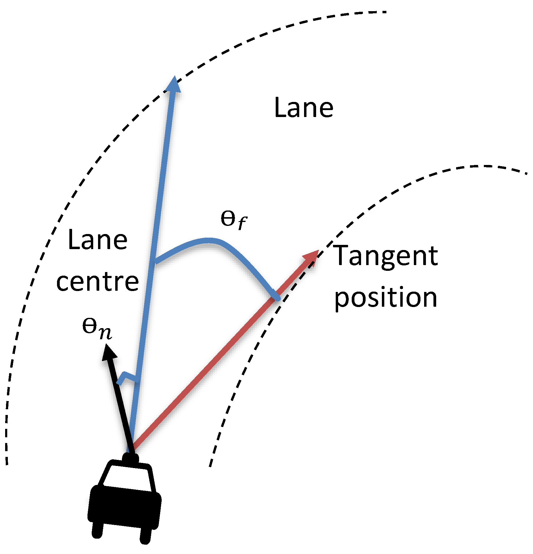
3.1. Hidden Markov Model (HMM) for Driving Behaviour

According to Jin et al. [51], a driving behaviour can be represented as a succession of basic movements related, respectively, to a specific state of the driver, the vehicle, and the road. They proposed a continuous HMM model of driving behaviour in lane-keeping and lane-changing to the left or right based on observable state variables, such as steering wheel angle and velocity. The left–right HMM corresponded to the transition variables, the hidden state of the driver’s manoeuvre, and the observable state variables, the experimental approach is given in ([52], Figure 3). The model could not transition backwards but could stay in a specific state or move forward. The results indicated that 80% of the driver’s manoeuvres were correctly recognised. The vehicle’s accurate control data, such as braking, steering, and acceleration, were modelled as a set of HMMs to detect the driver’s intention in a stopping action after driving without any manoeuvres. The outcome indicated an average accuracy of 95% fitting to the ground truth. Furthermore, Tran et al. [53] proposed a driver model based on HMM that predicted the driver’s intention on six tasks (stopping, driving without action, changing to the left lane, changing to the right lane, turning left, turning right) with high time efficiency. They used the car control information and the vehicle state data in that work. The results showed an accuracy of 86% on recognition of a driver’s manoeuvre and the best recognition time for stoping, left-turning, and right-turning tasks. Meng et al. [54] suggested modelling individual driving behaviour using machine learning methods and HMMs to avoid vehicle theft as represented in ([54], Figure 2) The HMM model information for each driver was evaluated using the HMM training procedure. The estimated model parameter was then executed to various driving behaviour models based on a test, then the driver identity with the best matches was selected. Steering, accelerating, and braking data were collected and used as observable variables. After simulation in the driving environment, the driving behaviour model’s performance showed 80% accuracy compared to the ground truth. Since HMM is sometimes inefficient because it cannot integrate past and input data, autoregressive input and output HMM (AIOHMM) were proposed to overcome the HMM limitation and obtain a better driving behaviour model based on driver visual direction, gas pedal, and steering wheel. It occurred that the AIOHMM driver’s model had the best precision with five hidden states for different tasks (turn left, turn right, go straight, follow participant) [55]. However, HMM is not enough to provide a better driving prediction model for all drivers due to individual driving behaviour. Therefore, Qi and Dirk [56] developed an enhanced forecasted model depending based on the fuzzy logic HMM. This proposed model increased the detection accuracy performances and lowered the number of false alarms. In this work, the fuzzy logic was employed to split the driving events into dangerous, very safe (vs), and safe driving scenarios (s), and every situation was modelled using HMM as illustrated in ([56], Figure 3). Left lane change, right lane change, and lane-keeping (LK) were the hidden states, whereas steering angle, accelerator position, and brake pressure were the observable state variables. The proposed model demonstrated an outstanding enhancement (an average of 85% accuracy rate). Amsalu et al. [57] developed an HMM based on the genetic algorithm (GA) to model driving behaviour when approaching road intersections to reduce the vehicle accidents occurring in these areas. This model could assist the advanced driver assistance system (ADAS) in employing better decisions to reduce accidents. The GA was utilised to optimise the HMM parameter to provide a model with the best intention detection rate. The outcome indicated that the HMM-GA improved driving behaviour predictions at an intersection by 10% more than the HMM. An HMM model where the road direction combined with a manoeuvre to predict the driver intention was suggested by Sathyanarayana et al. [58]. The experiment results after the experiment in the simulation environment showed a 100% improvement in recognition rate for the right turns, 85% for the left turns, and 87% for lane changes. The car position, wheel angle, and acceleration were set as hidden states, and time, velocity, and lane changing were set as observable states and were used to enhance the capacity of modelling the uncertainty of the driving behaviour model based on the association of HMM and Dempster–Shafer theory (DSP). It was shown that HMM-DST gave a significant outcome for the driver’s intention model rate with 84% for the vehicle positions (X, Y), and 76%, respectively, for steering angles and accelerations [59].

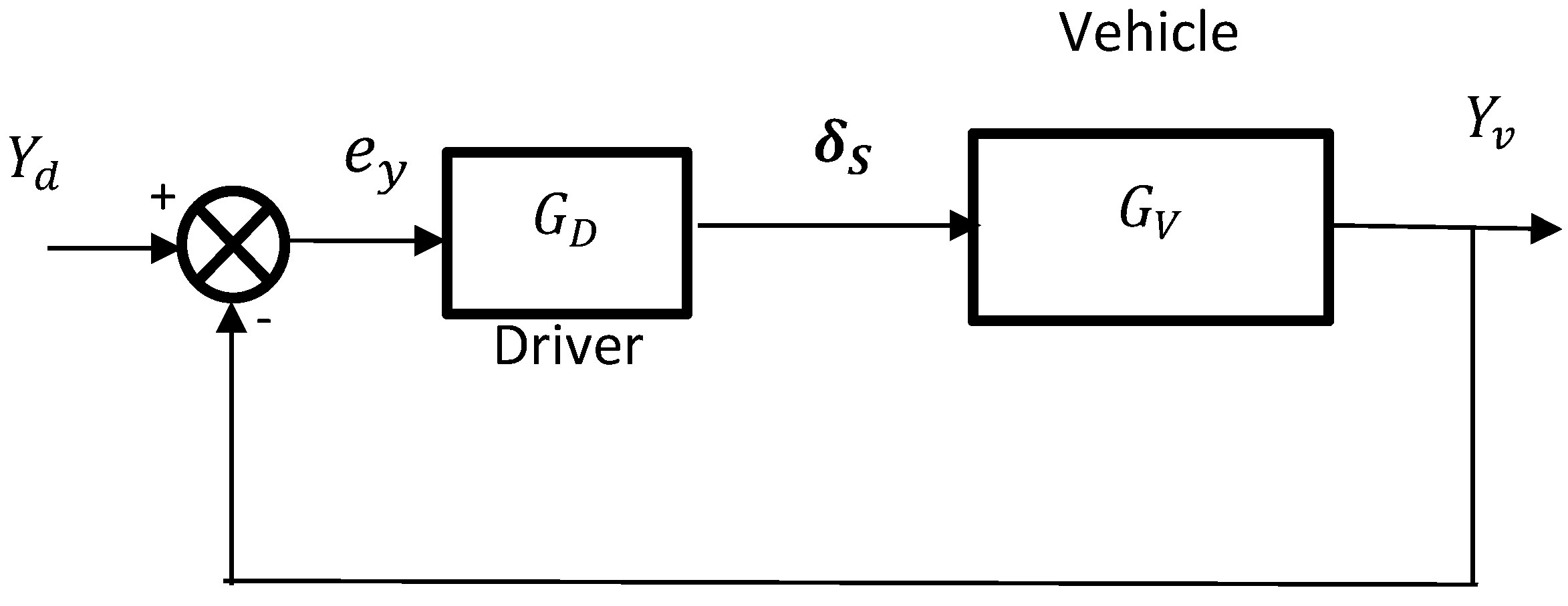
3.2. Control Theory Model for Driver–Vehicle Systems

The car lateral and longitudinal control is a typical closed-loop system. As shown in Figure 1, the actual vehicle position Y v in the lane is compared to the desired position Y d by the driver, and then the steering wheel angle δ s is adjusted to meet the reference position. In these systems, drivers are seen as controllers.
Hess and Hess [60] used control theory to model driving behaviour as both a high and a low frequency in the frequency domain to stabilise the system when adjusting the vehicle. The results have indicated that the model matched the experimental data at 82% for lateral displacement. This model only used the lateral error as input to generate the driver steering angle as output and did not account for the compensatory tracking movement (visual input). MacAdam [61,62] Considered the implementation of driving tasks as a linear time-invariant system, with an optimal preview strategy to model driving behaviour by taking visual information when following a specific driving path and predicting the next car steering action (steering response). Based on the single-input and single-output (SISO) linear system, MacAdam developed the following state equation and the minimising cost function (Equations (3) and (4)) to monitor and model the steering wheel behaviours:
x ˙ = A x + B u y = C x
u o p = 1 T t t + T s [ [ y r ( η ) y ( η ) ] Φ ( η t ) ] 2 d η }
where u ( t ) is the steering input operated in the actual preview interval ( t + T s ), T s is the preview time, y r ( t ) is the reference of the lateral displacement, and y ( t ) corresponds to the output lateral displacement, which is a link to the current state x ( t ) and Φ ( t ) (the irrational weighting over the preview period). Ungoren and Peng [63] improved MacAdam’s model by incorporating the optimal preview strategy into an adaptative preview control and considered the vehicle driving process as a non-linear model. This model took the yaw angle and vehicle position errors into the optimisation cost function. As a result, the cost function gave more resilience to modelling various driving behaviours. In addition, the driving steering action was not forced to be constant during the preview time, which improved the matching performance of MacAdam’s model.

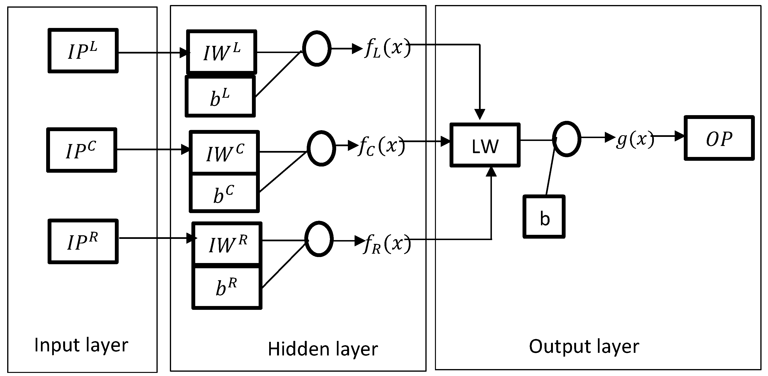
3.3. Neural Network Model for Driver’s Behaviours

Mathematical and empirical approaches were developed to model driving behaviours based on the first principle of physic and regression technique, where several simplifying assumptions occurred. However, human behaviours and vehicles are complex and non-linear time-varying systems. With the evolution of intelligent technology, driving behaviour models were designed using neural networks, where massive data is used to train the model. Neural networks have the advantages of providing a model without prior knowledge of the system, compared to others such as statistical models [64]. The second advantage is that it handles complex, non-dynamic data, and also disturbance data [65]. The training and learning process allows the network to adjust the weights and biases towards the desired output.
Fujioka et al. [66] developed a driving steering behaviour model using a neural network. This model used the lateral error, the yaw angle (input) data, and the steering angle (output) data to train the neural network with data obtained from a virtual driving environment. MacAdam [67] constructed a two-layer elementary back-propagation neural network with adaptive learning evaluation to improve the driver steering behaviour model in curvature and lane-changing manoeuvres. This approach included time delay information of different displacements in neural network input data. To constitute the driver model, the steering wheel angle was mapped as a function of lateral displacement. Sensors mounted on the actual vehicle allowed for time delay and accurate data collection. The output model matched the target at a 90% level. The studies described by Yang et al. [68] made use of a two-layer neural network with 12 neurons in the first layer to model the driving behaviour. However, they took the trailer and the tractor input data into consideration instead of the vehicle. In this work, only the lateral model was utilised.
Lane changing is one of the every-day driving activities involved in traffic. Hunt and Lyon [69] used the back-propagation learning algorithm to predict driving-decision-making behaviours for roadway changes. In this work, the neural network driver modelled problems that occurred from previous research on lane change, such as lack of output prediction for a sudden lane change and lack of real data from the driving environment. Their work examined a visual pattern as the input representing the driving environment around the car that was about to change lanes. Possible information between drivers was not considered.
To overcome the use of NN to model driving behaviours in lane-change tasks, Zheng [70] used the feed-forward neural network with a large amount of trajectory data collected from the Next Generation Simulation (NGSIM) program with an input layer of three input vectors, namely, I P L , I P C , and I P R , as well as a hidden layer and an output layer. Any input vectors were variables linked with the car in the left, current, and right lanes (see Figure 2). IW, LW, and b i were the weights and biases, which were adjusted to obtain the desired lane-change operation (left, current, right) using the hyperbolic tangent sigmoid function (see Equation (5)).
f i ( x ) = 2 1 + e ( 2 x ) 1 , i ε [ L , C , R ] .
The results demonstrated that the predicted performances by NN were 94.6% for left lane changing and 73.3% for right lane changing, compared to 13.3% (left lane change) and 3.3% (lane change to the right) for a model designed by a multinomial logic (MNL).
In the above work, the lateral displacement was the only input to the neural network model. Therefore, they did not consider the yaw angle’s acceleration and velocity.
Lin et al. [71] used a radial basis function network (RBFN) to model driving behaviour in various situations (lane changing, overtaking, and S-curves). The training data were collected from a natural driving environment. The angular velocity and steering wheel angle were mapped as a function of the lateral velocity, yaw angular velocity, lateral acceleration, roll angle, roll angle velocity, lateral displacement, and the preview offset. Although the simulated and experimental results were very close, delays were noted in the simulated results on the S-curve activity. This delay could be due to the high workload and short period allocated to preview time.
A misinterpretation of the vehicle motion characteristic and the time related to lane changes by the driver may lead to a traffic accident and cause fatal damages [72,73]. Peng et al. [74] used the back-propagation neural network (BPNN) to model the intentions of the driver for intending to change or stay in a lane. Various parameters, such as eye and head movement, vehicle motion state, car running behaviour, and driving condition naturalistic data, were inputs to the BPNN of an input layer with 7 neurons and a hidden layer with 15 neurons. The outcome indicated that the model predicted the driver intention for lane-keeping up to 85.44% accuracy and 95.63% for lane-changing intention.
As with lane changes, vehicle-following is a part of every-day driving activities. Preview driver theory provides a piece of important information on driver previews. Cao et al. [75] built a preview optimal artificial neural network (POSANN) human driving behaviour model, as shown in Figure 3.
In the model, f e is the road data received through the human transfer function e t p s from the target information f. They took into account the inertial delay of the system 1 1 + t h s . The predicted steering angles δ were mapped as a function of w 1 , w 2 , w 3 , w 4 , which reflected the weights of the road data f e , the lateral displacementy, lateral velocity y ˙ , and the lateral acceleration y ¨ , respectively. However, the NN model could not predict the correct output when a sudden lane change occurred. Cao et al. [75] later improved the model by introducing jerk dynamics into the PSONN; the steering wheel angle δ S W was modified by jerk dynamics. Chong et al. [76] proposed a fuzzy rule-based neural network (FRNN) to predict driving behaviour with naturalistic data produced by the Naturalistic Truck Driving Study (NTDS) in various driving situations (car-following and safety). The fuzzy rules had the duty to choose the best weights option and update different weights based on reinforcement learning. On the other side, NN updated the weights from the start until the final stage. The results showed that the fuzzy-based NN model had an accuracy of 98% and 97%, matching with naturalistic data in car-following and safety situations, respectively. However, this model could not be used in lane-change activities, and truck data were used instead of data from regular cars.
Many proposed approaches in the literature for modelling driving behaviour were reviewed in this section. Based on various tasks, different driver model classification approaches were presented with their improvements and possible drawbacks.
Table 2 illustrates different proposed methods for developing and enhancing driving behaviour models in various driving tasks with possible drawbacks. Table 2 also highlights that the lane-keeping task is the most used. The review indicated that the HMM driving behaviour model was improved by adding optimisation or machine learning techniques. The driving behaviour model based on the neural network method was model-free, against the control theory model based on mathematical principles with many assumptions.

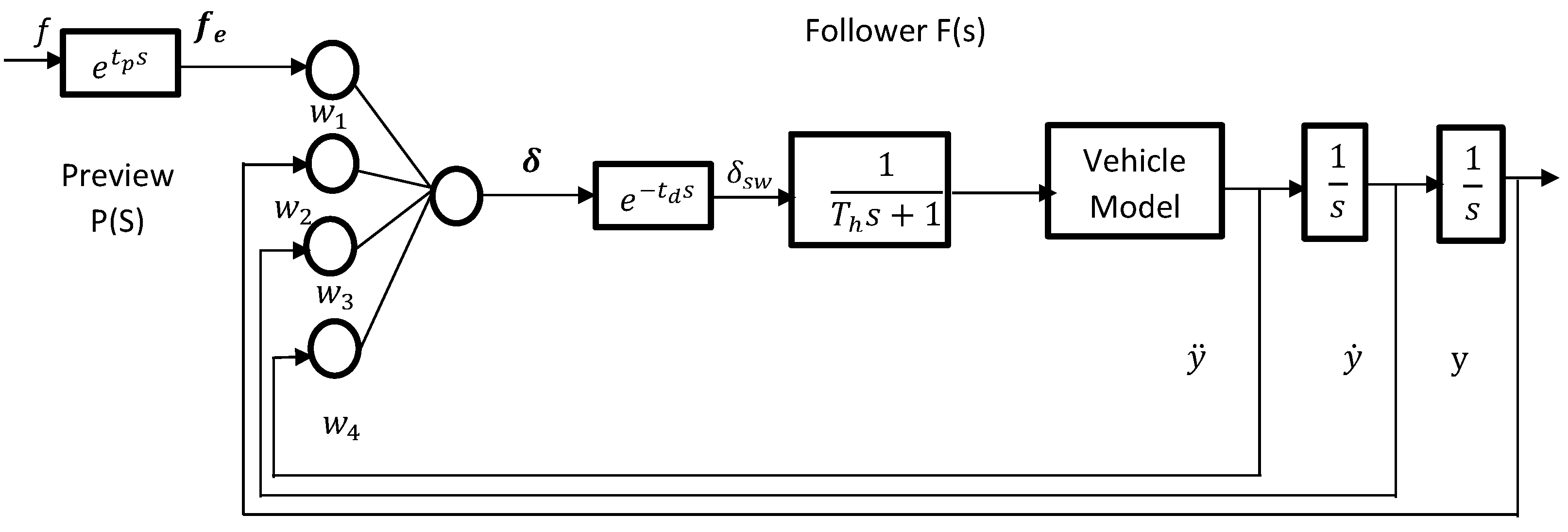
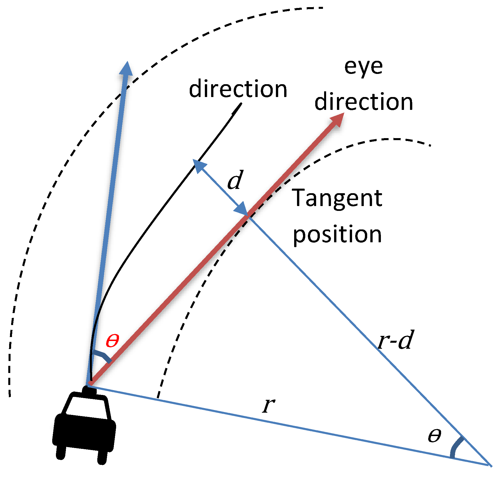
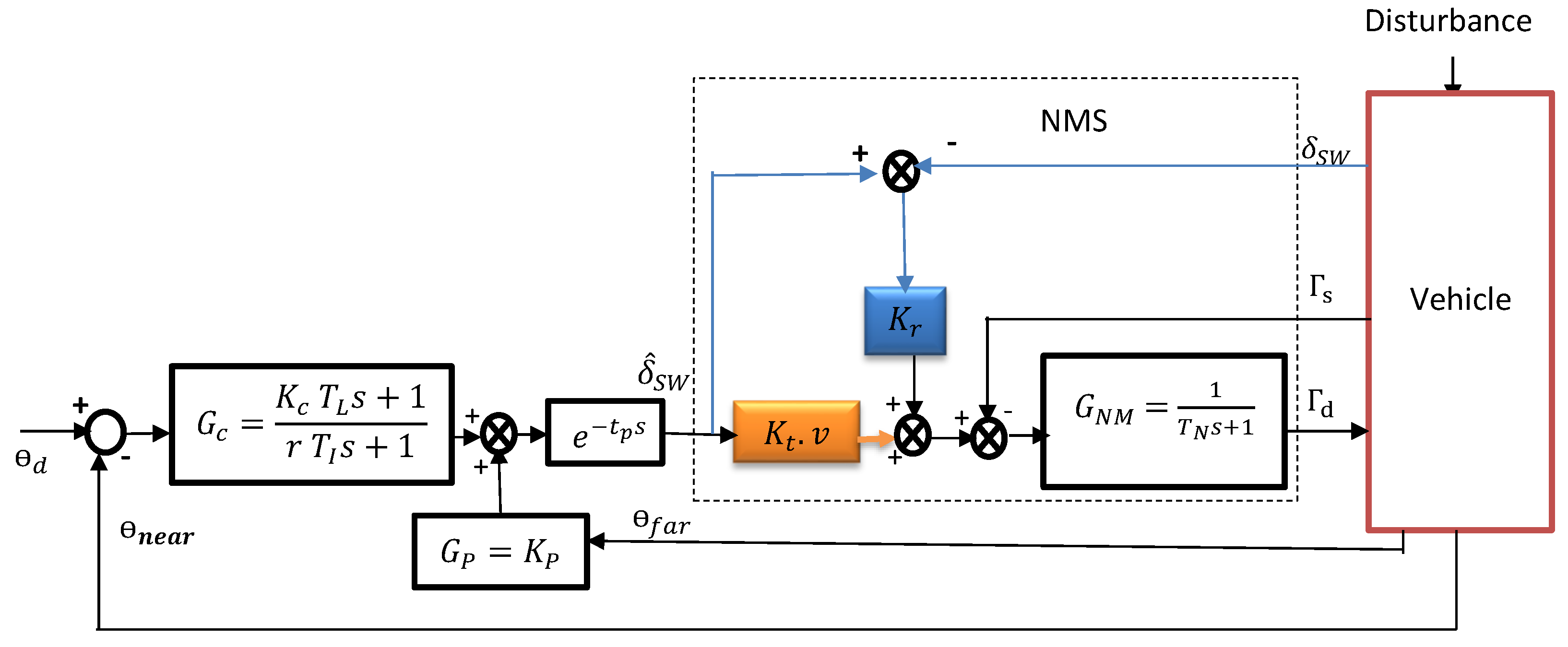
3.4. Driving Behaviour Model in Haptic Guidance System

Researchers have considered the human driving behaviour in closed-loop haptic guidance systems to further improve the driving performance during lane-keeping tasks. Wang et al. [19] proposed a driving behaviour model in haptic guidance systems. This model took into account a two-point visual driving model, with the lateral error e y and the yaw error e θ as the inputs; the steering behaviour model was then obtained since the driver’s steering actions were the results of visual feedback. In this model, T h and K h are the haptic guidance torque and the coefficient of the haptic system, the detailed block diagram can be seen in ([19], Figure 3). The reliance on the shared haptic control depended on the coefficient of K h . The driver steering behaviour relied on the haptic guidance when K h was zero. For K h = 1, the driver was independent of the haptic guidance system. T h depended on the e y and e θ , as shown Equation (6) [19], where c 1 , c 2 , and c 3 are constant gains for e y ( n e a r ) , e θ ( f a r ) , and e ˙ θ ( f a r ) , respectively. It was indicated that the driver visual feedback model combined with haptic guidance matched the human driver input torque at 68% fitness.
T h = K ( c 1 e y ( n e a r ) + c 2 e θ ( f a r ) + c 3 e ˙ θ ( f a r ) )
Steering a car needs visual information about the road environment, such as straight lines and curves. Land et al. [77] proposed a driver steering model negotiating a bend based on the road’s tangent point (TP), which is the changing direction of the inside edge curve, as shown in Figure 4. The TP was used to derive, neglecting the absolute distance, C = θ 2 /2d = 1/R, where θ is the angle between the car’s heading direction and the tangent point, d is the distance between the tangent point and the car trajectory, and R is the radius of the curve.
Salvucci and Gray [78] redefined the two-level control model of driver’s steering as a proportional–integral controller using two visual angles in front of the car as the inputs to minimise the change in direction of the near and far points and retain the angle to the near point close to zero, as referred to in Equation (7).
Δ φ = k f Δ θ f + k n Δ θ n + k I θ n Δ t
where Δ φ represents the change in steering variation, Δ θ f represents the contribution of the change in far-point visual direction, and Δ θ n represents the contribution of the change in near-point visual direction. A near point represents the lane centre at a close distance ahead of the car; it corresponds to the perception of the mid-position between the lane centre and the lane edge. The far point represents a distant point that is used to determine the upcoming roadway, as the curve indicates in Figure 5.
The link between the driver’s vision and his steering behaviour with force feedback was investigated by Franck Mars [79] when driving through the curve. A distance may be the vanishing point when driving down a straight road, such as the tangent point. The behavioural studies investigated the driver track when negotiating bends. This model was supported by behavioural studies.
Nevertheless, the driving behaviour models proposed above do not explain how the driver manipulates the steering wheel. Their outputs model are intention variables. A translation of this intention into a kinaesthetic approach or neuromuscular system needs to be made for a better model.
Saleh et al. [80] proposed a driver model that converts the visual output model into the steering wheel angle by using visual anticipatory and compensation feedback and the neuromuscular approach to negotiate a bend; see Figure 6.
In their model, K t , K r , and K p correspond, respectively, to neuromuscular reflex gain, angle to torque coefficient, and anticipation gain. In these studies, researchers determined the compensatory control where the rapid change of the car position was compensated for by the driver’s visual and kinaesthetic perception, based on the near point of view by the driver to keep the car positioned in a centre lane, with the transfer function model in Equation (8) [81].
G c = K c T L s + 1 T I s + 1
where K c , T I , and T L are the gains relevant to the actions of the driver concerning the near visual angle error, and the lag and lead time constants, respectively. Adjusting the driving behaviour parameters leads to the maintenance of the vehicle’s position on the lane or a reduction in the lateral displacement error. The time delay from processing information of the central nervous systems was also considered in [81] (Equation (9)):
G L = e τ p s
where τ p is the constant delay.
Mars et al. [82] developed a cybernetic driver steering model by considering the visual anticipatory, compensatory, and the sensorimotor data. The anticipatory part affects the θ f a r (which represents the angle between the tangent point and the vehicle heading) to negotiate the curvature (see Figure 6). The compensatory section G c kept the near angle θ n e a r (which corresponds to the proportional distance of the car to the centre lane) close to zero to keep the vehicle in the lane. Figure 7 illustrates different inputs (far and near angle) to the sensorimotor model. The neuromuscular transfer function corresponding to approximate the driver’s arm was proposed by [83] as shown in Equation (10):
G N M = 1 T N s + 1
Both the anticipatory and compensatory visual steering angle δ s w ^ and the feedback torque Γ a were introduced into the neuromuscular compensation system to allow the driver to provide the proper output torque Γ d . The aim was to reduce the car’s lateral position or keep the vehicle in the lane [80,81]. The result showed that the driving behaviour model obtained from real driving data was almost identical to the human driver. It was simple to use for smart steering assistance systems.

4. Driver–Vehicle Systems Control

Uncertainty derived from the human driver mathematical model and vehicle dynamics must be corrected. Control system theory seems to be one of the best approaches to assist in this aim. However, choosing the best control tool depends on the nature of the structure of the present model. Discussion of the theoretical and analytical tools used to control vehicle systems is attended to.

4.1. Model Predictive Control

Model predictive control (MPC) is a feedback control algorithm that uses the model to optimise and predict the future output of the system. A multivariable controller monitors the work simultaneously by considering all interactions between system variables. It has the advantage of considering constraints, such as speed limit, lateral range on the input, and more system states. Based on the above characteristics, researchers have used MPC to control driving behaviour by providing a steering action by minimising the cost function involving car path errors and dynamics. A PID tracking control was associated with MPC to form a feedback driver controller used to control the driver’s steering, accelerating, and braking behaviour by minimising a cost function containing the lateral and speed deviations and errors [84]. However, the controller could not compensate for different driving behaviours due to the individual driving profiles. Moreover, only a single car’s dynamic model was considered and did not extend to any learning mechanisms. Later, Pick et al. [85] included the hand wheel angle derived from the driver arm transfer function, the vehicle position deviation, and the heading error to the cost function to minimise it. This cost function was derived from the optimal preview strategy to control the human driver steering behaviour further. Since human cognitive processes are different from individual to individual, the transfer function of the driver is also different due to processing time delays and more factors, so the cost function can also be influenced by different driver attitudes or driving styles. Keen and Cole [86] developed a steering compensator deriving from a linear MPC by applying the formal system identification technique to the real double-lane-changing tasks to minimise the predicted steering angle error. This identification technique was used for data collected from 14 test drivers in an instrumented vehicle. The avoidance of identification bias from the closed-loop driver–vehicle system was taken into account too.
However, most of the above works considered the driver as a linear and time-invariant system. In fact, driver actions and tasks are different and time-varying. Therefore, the driver–vehicle system is a non-linear and time-varying system. Based on the preview theory, Guo et al. [87] combined model predictive control (MPC) developed by [88] and the PID to model the driver steering behaviour control. The MPC was conducted to minimise the lateral displacement error in their proposed studies and to predict the driving behaviour control action. The neuromuscular system and the neural response of the driver were considered. The PID controller was designed to model the driver braking and accelerating control by minimising the longitudinal velocity error.
The work conducted in [87] was later improved by adding the vehicle inverse information to the longitudinal driver control. This study was extended using the MPC to monitor a non-linear time-variant driver steering operation. Highly skilled, less-skilled, and novice-driver steering behaviours were developed by tuning the degree of prior knowledge that the controller holds on the non-linear dynamics. The results confirmed that the steering control accuracy depends on the variation of the controller knowledge of the system [89]. However, more assumptions were made on different driver skills (highly skilled, less-skilled, and novice-driver steering). Based on the perception information, decision, and execution module, the human driving behaviour (longitudinal and lateral) was modelled by Qu et al. [88,90]. As highlighted in ([90], Figure 1), the perception module was derived from the driver preview point information for path-following, including the preview time ( T p ), the vehicle’s longitudinal velocity ( v x ), and then the distance from the car to the preview position X = T p v x . In the decision module, the minimisation cost function shown in Equation (11) was designed to reduce the lateral and longitudinal errors and, therefore, to mimic the human driver’s aptitude to predict the car’s future state due to the differential flatness.
J = ( y d ( t ) t t + T p v y ( τ ) ) 2 d ( τ ) + t t + T p v x ( τ ) ( v g o a l ) 2 d ( τ )
where y d , v y , v x , v g o a l , and T p correspond, respectively, to the lateral desired preview point, the car’s lateral velocity, the car’s longitudinal velocity, the longitudinal desired velocity, and the preview time. In the execution module, a PID controller was developed to simulate the driver’s capability to tune the error between the desired and the current accelerations. As a result, the reference path was tracked accurately (lateral error = 0.3 m), and the velocity of the car was controlled (velocity error = 0.1 m/s) as well toward the best fuel consumption, with the steering wheel angle, brake angle, and throttle angle properly tuned.
Qu et al. [91] proposed a stochastic MPC (SMPC)-based driver steering controller where the road condition (icy, wet, and dry), preview point approach, preview time, weights condition, and time delay are considered. They used the disturbance of the road friction coefficient parameter with the internal vehicle dynamic to develop the driver steering knowledge on various road conditions. The cost function, including the weighted combination of lateral path error and ease of human driver control, is minimised by the SMPC. The simulation results showed that a higher factor in driver control eases poor tracking performance in all road conditions. For example, a high preview point (10 m–15 m) on an icy road resulted in a good tracking path compared to a low preview point. Likewise, a low preview time and small transport delay time led to a good tacking pathway on a dry road. This study revealed that the SMPC-based steering control was more robust than MPC because of its ability to deal with uncertain situations. Although this control model showed a positive tracking path, it is essential to note that the road friction coefficient and vehicle internal dynamic formulations were based on mathematical and many other assumptions.

4.2. Proportional-Integral-Derivative (PID) Control

PID control was applied to mimic the driver’s steering wheel at a distant point. However, the preview point or gazing distance varies depending on the driving tasks and road situations. Therefore, Shida et al. [92] proposed a PID controller with conventional feedback with H L ( s ) as the human driver model was represented in ([92], Figure 1). The relationship between gazing distance and the PID gain was considered. The driving actions are involved in the PID gains, such as the proportional gain K P used for the lateral error, the derivative gain K D to predict the lateral deviation, and the integral gain K I used to squash the steady error. H d ( s ) represents the driver action model with human dead time in Equation (12).
H d ( s ) = ( K P + K D s + K I 1 s ) e τ s )
The PID’s parameters K P , K D , and K I were obtained from a particle swarm optimisation where an evaluation function, containing the driving simulation error and the model error, was minimised to make H d ( s ) close to the human driving model. This controller was more effective than conventional PID controllers.
Menhour et al. [93] proposed a robust control system using two PID controllers to control the lateral displacement and the yaw angle from a single input. The PID parameters were designed by a linear quadratic regulator (LQR) and the linear matrices inequality optimisation approaches by determining a controller from the LQR matter that minimised the quadratic cost function. The results revealed that the lateral displacement deviation and yaw error were reduced in trajectory tracking tasks. Furthermore, the proposed model resisted uncertainties and non-linearity (high lateral acceleration) due to its robustness and stability. However, only the trial-and-error method was used.
Niu and Sun [94] designed a PID controller to control the accelerator leg of a robot driver. The PID parameters were obtained from a critical proportioning method derived from the mathematical transfer function of a robot’s accelerator leg. In addition, the transient response was assessed, such as the rise time and the settling time. However, the mathematical model was based on many assumptions; therefore, it cannot resist uncertainty and a high degree of non-linearity.
The active front steering system was improved by combining the conventional PID and the fuzzy PID controllers. The parameters ( K P , K D , and K I ) were chosen or adjusted using fuzzy inference. These fuzzy PID controllers improved the system by increasing the response speed (reducing the rising time), and decreasing the overshoot, while the conventional PID was used to diminish the displacement error and match the tracking trajectory [95].

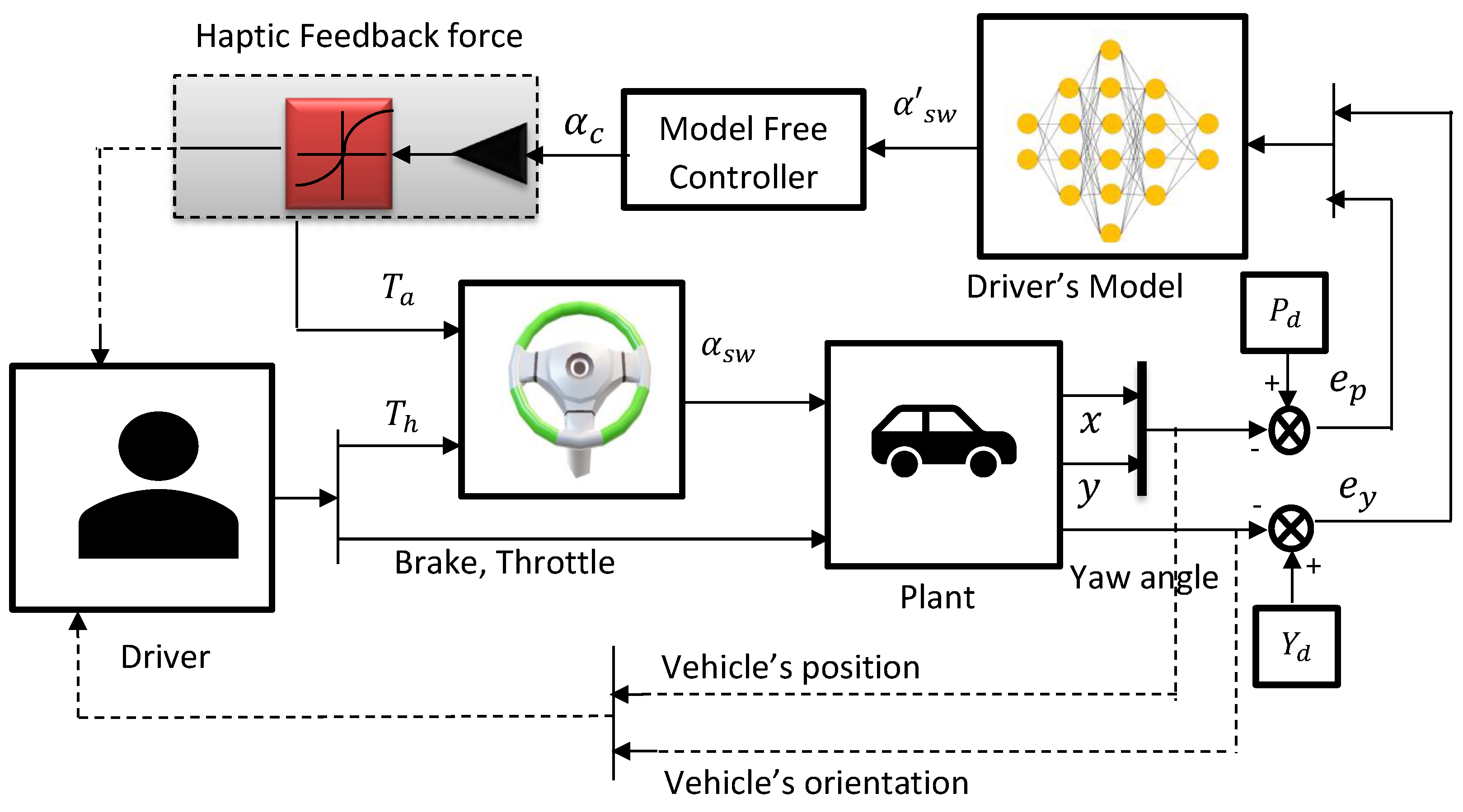
4.3. Controller in Haptic Feedback System

Ercan et al. [96] developed an MPC to assist the driver in a haptic guidance system (lane-keeping system). The controller’s purpose was to keep the car in the lane and enhance safety. The cost function used in this MPC considered the driver arm impedance model, the safety constraints such as lane boundary, and the input constant such as overlay torque (controlled input). The predictive controller evaluated and updated the most-appropriate guidance torque that minimised the loss function. The results showed that the MPC-based lane-keeping controller reduced the driver workload by diminishing the guidance torque and solving the conflict between the driver and the assistive system in shared control for trajectory tracking tasks. However, the driver arm impedance behaviour was modelled based on mathematical assumptions; therefore, it will face a robustness problem.
Lazcano [97] designed an advanced MPC-based haptic controller to improve the driver model based on cognitive processes. The neuromuscular and car steering dynamics were considered to enhance the interaction between the driver and the assistive system. The trajectory tracking performance aimed to reduce the lateral error based on the steering angle. The collaborative comfort was improved due to the lateral displacement and the yaw rate. In this work, the cognitive controller used an LQR to predict the future state of the driving behaviour. The predicted torque was evaluated to provide guidance torque during a steering action by minimising a cost function with constraints on torque assistance, steering angle, yaw rate, and lateral velocity. The results indicated that for a known preview trajectory, the MPC-based haptic controller provided the best torque where the driver effort was reduced with the controller implementation, and the lateral error was smaller than the case without a human driver modelled Efremov et al. [98] proposed an MPC controller that used driver envelope restriction to assist the driver in lateral action. When driving through a curvature, the sideslip angle and the slip ratio on the tire forces were delimited and taken as a constraint for the MPC cost objective function. The primary purpose of the MPC controller was to predict the guiding steering wheel angle α M P C from a reference steering angle α d produced by the driver as shown in ([98], Figure 1). The deviation between the guiding steering wheel angle and the actual steering wheel angle was converted into a haptic force or torque T h , which was applied to correct the steering wheel angle error by an assistive system. The simulated results revealed that the controller assisted less-skilled drivers by limiting the error for drivers’ turning tasks [98,99]. However, this controller did not consider an appropriate driver model, so it could not provide good performance for different driving styles and is not suitable for a lane-keeping system.
Avoiding collision is one part of the driver’s duties. Balachandra et al. [100] proposed an MPC-based collision controller by providing predicted haptic feedback that assists the driver in avoiding obstacles. Furthermore, the MPC controller used the velocity and lateral constraints to offer an optimal steering angle that matches the human steering angle. In other words, the MPC controller found the best tire force for keeping the vehicle within the constraint boundaries and minimising the cost function (see Equation (13)).
M i n i m i s e k = 1 10 | F y f , d r i v e r ( k ) F y f , o p t ( k ) | + k = 1 30 γ ( k ) | | F y f , o p t ( k ) F y f , o p t ( k 1 ) | | 2
where F y f , d r i v e r ( k ) and F y f , o p t ( k ) are the front-tire forces represented, respectively, by the driver’s actual steering angle and the driver-predicted steering angle. k is the time step. The simulation outcome showed that the predicted haptic feedback could significantly alert drivers to adjust more quickly for obstacle-avoidance actions. However, it could not compensate for different driver steering behaviour errors or driving styles.
Table 3 summarised various driving behaviour controllers to enhance driving behaviour in a driver–vehicle–road system, without and with a haptic feedback effect. This table focuses on different types of driving behaviour controls in various haptic systems. The proposed controllers were highlighted in this table, with their benefits and improvements and their drawbacks discussed.

5. Prospective Directions for Developing a Robust Controller Considering Differences in Driving Behaviours in Haptic Systems

Human cognitive behaviours can affect driving activities, such as perception (eyes, skin, muscle), knowledge (training, experience), and decision-making abilities. For example, different drivers have different perceptions and understandings of the objectives in the tasks to be completed, which can affect the eyes and hand coordination and, therefore, the driving performance. However, it is not easy to find a principle that governs driving behaviour and vehicle dynamics, so the mathematical or statistical models used by some researchers are based on assumptions. This leads to uncertainties when these assumptions are not satisfied in real applications. An artificial neural network, or a model-free approach, could be more suitable for modelling complex non-linear systems, such as driving behaviour with more real or experimental input–output data.
The driving behaviour modelling approach, and the driving behaviour controller (The steering wheel angle control) with a haptic feedback system analysed from the literature have perfectly matched with and improved the steering wheel performance. However, challenges such as false alarms, vibrations on uneven roads, and the lack of an accurate driving behaviour model adversely impacted its performances. Furthermore, mathematical principles, statistical approaches, and the lack of consideration of the individual differences in a driver–vehicle–road system make the modelling and the controller less robust and inefficient for diverse-driving-style optimisation. Therefore, it is essential to design a model-free compensation system considering the driving behaviour model, with the individual differences of drivers taken into account, which predicts the real intention and implements it into a haptic system.
Figure 8 represents the prospective model where the model-free controller inputs are fed by a neural network that was mapped by the inputs (lateral position ( e p and yaw angle error e y ) and output (steering wheel angle ( α s w ), throttle, brake) of the human object. The steering wheel angle α s w resulting from the NN is included in a model-free compensating system. The controller is then trained to provide the corresponding steering wheel angle α c which will then tune a haptic feedback torque to correct the existing errors (displacement error, yaw angle error) due to uncertainties. The future recommended model composites a hybrid human-in-the-loop system. It could be necessary to synthesise such a system in the view of control system theory to ensure the system performances, such as transparency and robustness.

6. Discussion

This paper discussed and presented an analysis and comparison of different haptic systems’ impact on driving behaviour performance. The driving behaviour modelling system was investigated and the driver behaviour control in the driver–vehicle–road system with and without haptic feedback was explored. The outcome of the studies indicated that the haptic warning system mostly used vibration as the transmission signal, while haptic guidance used a shared control force feedback. Moreover, the haptic feedback was applied to the drivers to enhance their driving performance (reducing the lateral displacement errors and the orientation deviation), lower the response time, and reduce the mental workload (awareness of surroundings, lane departures, collision prevention). However, false alarms, vibrations on uneven roads, and the lack of an accurate driving behaviour model adversely impacted its performance. The conflict between the haptic guidance system torque and the driver was noted when the driver’s steering intention differed from the assistive system. In addition, the after-effect matter, which occurs when a driver is expecting force feedback (torque), but the system provides null, has been considered.
Implementing the driving behaviour model based on neuromuscular dynamic and visual feedback into the shared haptic control system has improved the driving performance and significantly reduced the driver and haptic guidance conflict. Although the investigation results of the techniques used to model driving behaviour have presented promising results, such as perfect matches, the models based on the mathematical model are less robust due to the many assumptions made by them. Statistical approaches, such as HMM using the sequence of necessary action to represent driving behaviour, were based on the actual and future state, but did not consider the past state. HMMs, combined with other techniques, were proposed to fulfil the lack of not using past input information. The artificial neural networks developed to mimic the driving behaviour were attended to meticulously. However, the model’s lack of real data and vulnerability to sudden lane changes was noted.
This overview extensively discussed different driving behaviour models and controllers with and without haptic feedback. Despite the fact that fast response times and stability and displacement errors were obtained based on the optimisation technique, some proposed controls for enhancing driving behaviour deviations based on mathematical principles were less robust due to the many assumptions that were applied. Moreover, the lack of consideration of the individual differences in a driver–vehicle–road system makes the controller less robust and less efficient for different driving styles.
Thus, a prospective model-free controller was proposed which considered the drawbacks discussed in the literature to enhance the driving behaviour control’s performance (transparency and robustness), considering the differences in driving style (various steering wheel angles, yaw angle, velocity). Furthermore, it is necessary to synthesise such a system in the view of control system theory to ensure the system performances, such as transparency and robustness, which is to be covered in our future work.

Author Contributions

Conceptualisation, S.D., S.I.N.T. and K.D.; methodology, S.I.N.T. and S.D.; validation, S.D., K.D. and S.I.N.T.; formal analysis, S.I.N.T.; resources, S.D., S.I.N.T. and K.D.; writing—original draft preparation, S.I.N.T.; writing—review and editing, S.D., S.I.N.T. and K.D.; supervision, S.D. and K.D. All authors have read and agreed to the published version of the manuscript.

Funding

This research is partly funded by the National Research Foundation of South Africa (Grant: 145975), Yunnan Science and Technology Department Fund (YZ20210001), and Scientific Research Foundation of Department of Education of Yunnan Province (Grant: 2022J0635).

Acknowledgments

Our gratitude and appreciation go to the National Research Foundation, French South Africa Institute of Technology (F’SATI), and all members and colleagues of the Tshwane University of Technology (TUT), especially the Department of Electrical Engineering, for providing the facilities and material to conduct this research.

Conflicts of Interest

The authors declare no conflict of interest.

References

  1. De Waard, D. The Measurement of Drivers’ Mental Workload. Ph.D. Thesis, University of Groningen, Haren, The Netherlands, 1996. [Google Scholar]
  2. Pack, A.I.; Pack, A.M.; Rodgman, E.; Cucchiara, A.; Dinges, D.F.; Schwab, C.W. Characteristics of crashes attributed to the driver having fallen asleep. Accid. Anal. Prev. 1995, 27, 769–775. [Google Scholar] [CrossRef]
  3. Sun, P.; Song, R.; Wang, H.X. Analysis of the causes of traffic accidents on roads and countermeasures. Saf. Environ. Eng. 2007, 2, 2007. [Google Scholar]
  4. Navarro, J.; Mars, F.; Young, M.S. Lateral control assistance in car driving: Classification, review and future prospects. IET Intell. Transp. Syst. 2011, 5, 207–220. [Google Scholar] [CrossRef]
  5. Jermakian, J.S. Crash avoidance potential of four passenger vehicle Technologies. Accid. Anal. Prev. 2011, 43, 732–740. [Google Scholar] [CrossRef]
  6. Fenton, R.E. An improved man-machine interface for the driver-vehicle system. IEEE Trans. Hum. Factors Electron. 1966, 4, 150–157. [Google Scholar] [CrossRef]
  7. Endsley, M.R.; Kaber, D.B. Level of automation effects on performance, situation awareness and workload in a dynamic control task. Ergonomics 1999, 42, 462–492. [Google Scholar] [CrossRef] [Green Version]
  8. De Groot, S.; De Winter, J.C.; Garcia, J.M.L.; Mulder, M.; Wieringa, P.A. The effect of concurrent bandwidth feedback on learning the lane-keeping task in a driving simulator. Hum. Factors 2011, 53, 50–62. [Google Scholar] [CrossRef]
  9. Singh, H.; Bhatia, J.S.; Kaur, J. Eye tracking based driver fatigue monitoring and warning system. In Proceedings of the India International Conference on Power Electronics 2010 (IICPE2010), New Delhi, India, 28–30 January 2011; pp. 1–6. [Google Scholar]
  10. Parasuraman, R. Designing automation for human use: Empirical studies and quantitative models. Ergonomics 2000, 43, 931–951. [Google Scholar] [CrossRef]
  11. Abbink, D.A.; Mulder, M.; Boer, E.R. Haptic shared control: Smoothly shifting control authority? Cogn. Technol. Work. 2012, 14, 19–28. [Google Scholar] [CrossRef] [Green Version]
  12. Kienle, M.; Dambock, D.; Bubb, H.; Bengler, K. The ergonomic value of a bidirectional haptic interface when driving a highly auto mated vehicle. Cognition 2013, 15, 475–482. [Google Scholar]
  13. Mulder, M.; Abbink, D.A.; Boer, E.R. The effect of haptic guidance on curve negotiation behavior of young, experienced drivers. In Proceedings of the IEEE International Conference on Systems, Man and Cybernetics, Singapore, 12–15 October 2008; pp. 804–809. [Google Scholar]
  14. Goodrich, K.H.; Schutte, P.C.; Flemisch, F.O.; Williams, R.A. Application of the h-mode, a design and interaction concept for highly automated vehicles, to aircraft. In Proceedings of the IEEE/AIAA 25TH Digital Avionics Systems Conference, Portland, ON, USA, 15–19 October 2006; pp. 1–13. [Google Scholar]
  15. Petermeijer, S.M.; Abbink, D.A.; de Winter, J.C. Should drivers be operating within an automation-free bandwidth? Evaluating haptic steering support systems with different levels of authority. Hum. Factors 2015, 57, 5–20. [Google Scholar] [CrossRef] [PubMed]
  16. Bao, S.; Wu, L.; Yu, B.; Sayer, J.R. An examination of teen drivers’car-following behavior under naturalistic driving conditions: With and without an advanced driving assistance system. Accid. Anal. Prev. 2020, 147, 105–762. [Google Scholar] [CrossRef] [PubMed]
  17. Zokaei, M.; Jafari, M.J.; Khosrowabadi, R.; Nahvi, A.; Khodakarim, S.; Pouyakian, M. Tracing the physiological response and behavioral performance of drivers at different levels of mental workload using driving simulators. J. Saf. Res. 2020, 72, 213–223. [Google Scholar] [CrossRef] [PubMed]
  18. Wang, Z.; Zheng, R.; Kaizuka, T.; Shimono, K.; Nakano, K. The effect of a haptic guidance steering system on fatigue-related driver 34 behaviors. IEEE Trans.-Hum.-Mach. Syst. 2017, 47, 741–748. [Google Scholar] [CrossRef]
  19. Wang, Z.; Zheng, R.; Kaizuka, T.; Nakano, K. Driver-automation shared control: Modeling driver behavior by taking account of reliance on haptic guidance steering. In Proceedings of the IEEE Intelligent Vehicles Symposium (IV), Changshu, China, 26–30 June 2018; pp. 144–149. [Google Scholar]
  20. You, C.; Tsiotras, P. Optimal two-point visual driver model and controller development for driver-assist systems for semi-autonomous vehicles. In Proceedings of the American Control Conference (ACC), Boston, MA, USA, 6–8 July 2016; pp. 5976–5981. [Google Scholar]
  21. Saleh, L.; Chevrel, P.; Claveau, F.; Lafay, J.F.; Mars, F. Shared steering control between a driver and an automation: Stability in the presence of driver behavior uncertainty. IEEE Trans. Intell. Transp. Syst. 2013, 14, 974–983. [Google Scholar] [CrossRef]
  22. Klauer, S.G.; Guo, F.; Sudweeks, J.; Dingus, T.A. An Analysis of Driver Inattention Using a Case-Crossover Approach on 100-Car Data: Final Report. 2010. Available online: https://www.nhtsa.gov/document/analysis-driver-inattention-using-case-crossover-approach-100-car-data-final-report (accessed on 15 March 2022).
  23. Suzuki, K.; Jansson, H. An analysis of driver’s steering behaviour during auditory or haptic warnings for the designing of lane departure warning system. JSAE Rev. 2003, 24, 65–70. [Google Scholar] [CrossRef]
  24. Enriquez, M.; Afonin, O.; Yager, B.; Maclean, K. A pneumatic tactile alerting system for the driving environment. In Proceedings of the 2001 Workshop on Perceptive User Interfaces, Orlando, FL, USA, 15–16 November 2001; pp. 1–7. [Google Scholar]
  25. Onimaru, S.; Kitazaki, M. Visual and tactile information to improve drivers’ performance. In Proceedings of the IEEE Virtual Reality Conference (VR), Boston, MA, USA, 20–24 March 2010; pp. 295–296. [Google Scholar]
  26. Stanley, L.M. Haptic and auditory cues for lane departure warnings. In Proceedings of the Human Factors and Ergonomics Society Annual Meeting; SAGE Publications: Los Angeles, CA, USA, 2006; Volume 50, pp. 2405–2408. [Google Scholar]
  27. Morrell, J.; Wasilewski, K. Design and evaluation of a vibrotactile seat to improve spatial awareness while driving. In Proceedings of the 2010 IEEE Haptics Symposium, Waltham, MA, USA, 25–26 March 2010; pp. 281–288. [Google Scholar]
  28. Locken, A.; Buhl, H.; Heuten, W.; Boll, S. TactiCar: Towards Supporting Drivers During Lane Change Using Vibro-Tactile Patterns. In Proceedings of the 7th International Conference on Automotive User Interfaces and Interactive Vehicular Applications, Nottingham, UK, 1–3 September 2015; pp. 32–37. [Google Scholar]
  29. Ochiai, Y.; Toyoshima, K. Invisible feet under the vehicle. In Proceedings of the 3rd Augmented Human International Conference, Megève, France, 8–9 March 2012; pp. 1–2. [Google Scholar]
  30. Ahtamad, M.; Gray, R.; Ho, C.; Reed, N.; Spence, C. Informative collision warnings: Effect of modality and driver age. In Proceedings of the Eighth International Driving Symposium on Human Factors in Driver Assessment, Training and Vehicle Design, Snowbird, Salt Lake City, UT, USA, 22–25 June 2015; pp. 324–330. [Google Scholar]
  31. Scott, J.; Gray, R. A comparison of tactile, visual, and auditory warnings for rear-end collision prevention in simulated driving. Hum. Factors 2008, 50, 264–275. [Google Scholar] [CrossRef]
  32. Mohebbi, R.; Gray, R.; Tan, H.Z. Driver reaction time to tactile and auditory rear-end collision warnings while talking on a cell phone. Hum. Factors 2009, 51, 102–110. [Google Scholar] [CrossRef] [Green Version]
  33. De Rosario, H.; Louredo, M.; Dıaz, I.; Soler, A.; Gil, J.J.; Solaz, J.S.; Jornet, J. Efficacy and feeling of a vibrotactile frontal collision warning implemented in a haptic pedal. Transp. Res. Part F Traffic Psychol. Behav. 2010, 13, 80–91. [Google Scholar] [CrossRef]
  34. Fitch, G.M.; Kiefer, R.J.; Hankey, J.M.; Kleiner, B.M. Toward developing an approach for alerting drivers to the direction of a crash threat. Hum. Factors 2007, 49, 710–720. [Google Scholar] [CrossRef]
  35. Kurihara, Y.; Hachisu, T.; Sato, M.; Fukushima, S.; Kajimoto, H. Periodic tactile feedback for accelerator pedal control. In Proceedings of the 2013 World Haptics Conference (WHC), Daejeon, Korea, 14–17 April 2013; pp. 187–192. [Google Scholar]
  36. Ho, C. Haptic interface for the distracted drivers. In Proceedings of the 2008 SICE Annual Conference, Chofu, Japan, 20–22 August 2008; pp. 890–893. [Google Scholar]
  37. Petermeijer, S.M.; Abbink, D.A.; Mulder, M.; De Winter, J.C. The effect of haptic support systems on driver performance: A litera ture survey. IEEE Trans. Haptics 2015, 8, 467–479. [Google Scholar] [CrossRef]
  38. Mulder, M.; Abbink, D.A.; Boer, E.R. Sharing control with haptics: Seamless driver support from manual to automatic control. Hum. Factors 2012, 54, 786–798. [Google Scholar] [CrossRef]
  39. Griffiths, P.G.; Gillespie, R.B. Sharing control between humans and automation using haptic interface: Primary and secondary task performance benefits. Hum. Factors 2005, 47, 574–590. [Google Scholar] [CrossRef] [Green Version]
  40. Zhao, Y.; Pano, B.; Chevrel, P.; Claveau, F.; Mars, F. Driver model validation through interaction with varying levels of haptic guidance. In Proceedings of the 2020 IEEE International Conference on Systems, Man, and Cybernetics (SMC), Toronto, ON, Canada,, 11–14 October 2020; pp. 2284–2290. [Google Scholar]
  41. Lam, T.M.; Boschloo, H.W.; Mulder, M.; Van Paassen, M.M. Artificial force field for haptic feedback in uav teleoperation. IEEE Trans. Syst. Man-Cybern.-Part A Syst. Hum. 2009, 39, 1316–1330. [Google Scholar] [CrossRef]
  42. Mulder, M.; Pauwelussen, J.J.; Van Paassen, M.M.; Mulder, M.; Abbink, D.A. Active deceleration support in car following. IEEE Trans. Syst. Man-Cybern.-Part A Syst. Hum. 2010, 40, 1271–1284. [Google Scholar] [CrossRef]
  43. Alaimo, S.M.; Pollini, L.; Bresciani, J.P.; Bulthoff, H.H. A comparison of direct and indirect haptic aiding for remotely piloted vehicles. In Proceedings of the 19th International Symposium in Robot and Human Interactive Communication, Viareggio, Italy, 13–15 September 2010; pp. 506–512. [Google Scholar]
  44. Mars, F.; Deroo, M.; Charron, C. Driver adaptation to haptic shared control of the steering wheel. In Proceedings of the 2014 IEEE International Conference on Systems, Man, and Cybernetics (SMC), San Diego, CA, USA, 5–8 October 2014; pp. 1505–1509. [Google Scholar]
  45. Marchal-Crespo, L.; McHughen, S.; Cramer, S.C.; Reinkensmeyer, D.J. The effect of haptic guidance, aging, and initial skill level on motor learning of a steering task. Exp. Brain Res. 2010, 201, 209–220. [Google Scholar] [CrossRef] [Green Version]
  46. Crespo, L.M.; Reinkensmeyer, D.J. Haptic guidance can enhance motor learning of a steering task. J. Mot. Behav. 2008, 40, 545–557. [Google Scholar] [CrossRef]
  47. Lee, H.; Choi, S. Combining haptic guidance and haptic disturbance: An initial study of hybrid haptic assistance for virtual steering task. In Proceedings of the 2014 IEEE Haptics Symposium (HAPTICS), Houston, TX, USA, 23–26 February 2014; pp. 159–165. [Google Scholar]
  48. Abbink, D.A.; Cleij, D.; Mulder, M.; Van Paassen, M.M. The importance of including knowledge of neuromuscular behaviour in haptic shared control. In Proceedings of the 2012 IEEE International Conference on Systems, Man, and Cybernetics (SMC), Seoul, Korea, 14–17 October 2012; pp. 3350–3355. [Google Scholar]
  49. Wang, Z.; Zheng, R.; Kaizuka, T.; Nakano, K. The effect of haptic guidance on driver steering performance during curve negotiation with limited visual feedback. In Proceedings of the 2017 IEEE Intelligent Vehicles Symposium (IV), Los Angeles, CA, USA, 11–14 June 2017; pp. 600–605. [Google Scholar]
  50. Ervin, R.D. Influence of Weights and Dimensions on the Stability and Control of Heavy Trucks in Canada-Part 1; Roads and Transportation Association: Ottawa, ON, Canada, 1986; p. 272. [Google Scholar]
  51. Jin, L.; Hou, H.; Jiang, Y. Driver intention recognition based on continuous hidden Markov model. In Proceedings of the International Conference on Transportation, Mechanical, and Electrical Engineering (TMEE), Changchun, China, 16–18 December 2011; pp. 739–742. [Google Scholar]
  52. Miyazaki, T.; Kodama, T.; Furuhashi, T.; Ohno, H. Modeling of human behaviors in real driving situations. In Proceedings of the ITSC 2001, 2001 IEEE Intelligent Transportation Systems. Proceedings (Cat. No. 01TH8585), Oakland, CA, USA, 25–29 August 2001; pp. 643–646. [Google Scholar]
  53. Tran, D.; Sheng, W.; Liu, L.; Liu, M. A hidden Markov model based driver intention prediction system. In Proceedings of the 2015 IEEE International Conference on Cyber Technology in Automation, Control, and Intelligent Systems (CYBER), Shenyang, China, 8–12 June 2015; pp. 115–120. [Google Scholar]
  54. Meng, X.; Lee, K.K.; Xu, Y. Human driving behavior recognition based on hidden Markov models. In Proceedings of the 2006 IEEE International Conference on Robotics and Biomimetics, Kunming, China, 17–20 December 2006; pp. 274–279. [Google Scholar]
  55. Akai, N.; Hirayama, T.; Morales, L.Y.; Akagi, Y.; Liu, H.; Murase, H. Driving behavior modeling based on hidden Markov models with driver’s eye-gaze measurement and ego-vehicle localization. In Proceedings of the 2019 IEEE Intelligent Vehicles Symposium (IV), Paris, France, 9–12 June 2019; pp. 949–956. [Google Scholar]
  56. Deng, Q.; Soffker, D. Improved driving behaviors prediction based on fuzzy logic-hidden Markov model (fl-hmm). In Proceedings of the 2018 IEEE Intelligent Vehicles Symposium (IV), Changshu, China, 26–30 June 2018; pp. 2003–2008. [Google Scholar]
  57. Amsalu, S.B.; Homaifar, A. Driver behavior modeling near intersections using hidden Markov model based on genetic algorithm. In Proceedings of the 2016 IEEE International Conference on Intelligent Transportation Engineering (ICITE), Singapore, 20–22 August 2016; pp. 193–200. [Google Scholar]
  58. Sathyanarayana, A.; Boyraz, P.; Hansen, J.H. Driver behavior analysis and route recognition by hidden markov models. In Proceedings of the 2008 IEEE International Conference on Vehicular Electronics and Safety, Columbus, OH, USA, 22–24 September 2008; pp. 276–281. [Google Scholar]
  59. Bhatt, D.; Gite, S. Modeling techniques for driver’s lane changing behaviour. In Proceedings of the 2018 9th International Conference on Computing, Communication and Networking Technologies (ICCCNT), Bengaluru, India, 10–12 July 2018; pp. 1–7. [Google Scholar]
  60. Hess, R.; Modjtahedzadeh, A. A control theoretic model of driver steering behavior. IEEE Control. Syst. Mag. 1990, 10, 3–8. [Google Scholar] [CrossRef]
  61. MacADam, C.C. Application of an optimal preview control for simulation of closed-loop automobile driving. IEEE Trans. Syst. Man Cybern. 1981, 11, 393–399. [Google Scholar] [CrossRef]
  62. Macadam, C.C. Understanding and modeling the human driver. Veh. Syst. Dyn. 2003, 40, 101–134. [Google Scholar] [CrossRef]
  63. Ungoren, A.Y.; Peng, H. An adaptive lateral preview driver Model. Veh. Syst. Dyn. 2005, 43, 245–259. [Google Scholar] [CrossRef]
  64. Karlaftis, M.G.; Vlahogianni, E.I. Statistical methods versus neural networks in transportation research: Differences, similarities and some insights. Transp. Res. Part C Emerg. Technol. 2011, 19, 387–399. [Google Scholar] [CrossRef]
  65. Rafiq, M.; Bugmann, G.; Easterbrook, D. Neural network design for engineering applications. Comput. Struct. 2001, 79, 1541–1552. [Google Scholar] [CrossRef]
  66. Fujioka, T.; Nomura, K.; Takubo, N.; Chung, D. Driver model using neural network system. In Proceedings of the SAE Technical Paper, International Pacific Conference on Automotive Engineering, Tokyo, Japan, 1 November 1991. [Google Scholar]
  67. MacAdam, C.C.; Johnson, G.E. Application of elementary neural networks and preview sensors for representing driver steering control behaviour. Veh. Syst. Dyn. 1996, 25, 3–30. [Google Scholar] [CrossRef]
  68. Yang, X.; Stiharu, I.; Rakheja, S. Study of driver factors affecting the directional response of an articulated vehicle using neural networks. Trans. Can. Soc. Mech. Eng. 1998, 22, 291–306. [Google Scholar] [CrossRef]
  69. Hunt, J.; Lyons, G. Modelling dual carriageway lane changing using neural networks. Transp. Res. Part C Emerg. Technol. 1994, 2, 231–245. [Google Scholar] [CrossRef]
  70. Zheng, J.; Suzuki, K.; Fujita, M. Predicting driver’s lane-changing decisions using a neural network model. Simul. Model. Pract. Theory 2014, 42, 73–83. [Google Scholar] [CrossRef]
  71. Lin, Y.; Tang, P.; Zhang, W.; Yu, Q. Artificial neural network modelling of driver handling behaviour in a driver-vehicle-environment system. Int. J. Veh. Des. 2005, 37, 24–45. [Google Scholar] [CrossRef]
  72. Jin, W.L. A multi-commodity lighthill–whitham–richards model of lane-changing traffic flow. Transp. Res. Part B Methodol. 2013, 57, 361–377. [Google Scholar] [CrossRef]
  73. Petzoldt, T.; Bruggemann, S.; Krems, J.F. Learning effects in the lane change task (lct)–realistic secondary tasks and transfer of learning. Appl. Ergon. 2014, 45, 639–646. [Google Scholar] [CrossRef] [PubMed]
  74. Peng, J.; Guo, Y.; Fu, R.; Yuan, W.; Wang, C. Multi-parameter prediction of drivers’ lane-changing behaviour with neural network model. Appl. Ergon. 2015, 50, 207–217. [Google Scholar] [CrossRef] [PubMed]
  75. Cao, J.; Lu, H.; Guo, K.; Zhang, J. A driver modeling based on the preview-follower theory and the jerky dynamics. Math. Probl. Eng. 2013, 2013, 952106. [Google Scholar] [CrossRef]
  76. Chong, L.; Abbas, M.M.; Flintsch, A.M.; Higgs, B. A rule-based neural network approach to model driver naturalistic behavior in traffic. Transp. Res. Part C Emerg. Technol. 2013, 32, 207–223. [Google Scholar] [CrossRef]
  77. Land, M.F.; Lee, D.N. Where we look when we steer. Nature 1994, 369, 742–744. [Google Scholar] [CrossRef]
  78. Salvucci, D.D.; Gray, R. A two-point visual control model of steering. Perception 2004, 33, 1233–1248. [Google Scholar] [CrossRef] [Green Version]
  79. Mars, F. Driving around bends with manipulated eye-steering coordination. J. Vis. 2008, 8, 10. [Google Scholar] [CrossRef] [Green Version]
  80. Saleh, L.; Chevrel, P.; Mars, F.; Lafay, J.F.; Claveau, F. Human-like cybernetic driver model for lane keeping. IFAC Proc. Vol. 2011, 44, 4368–4373. [Google Scholar] [CrossRef] [Green Version]
  81. Sentouh, C.; Chevrel, P.; Mars, F.; Claveau, F. A sensorimotor driver model for steering control. In Proceedings of the 2009 IEEE International Conference on Systems, Man and Cybernetics, San Antonio, TX, USA, 11–14 October 2009; pp. 2462–2467. [Google Scholar]
  82. Mars, F.; Saleh, L.; Chevrel, P.; Claveau, F.; Lafay, J.F. Modeling the Visual and Motor Control of Steering with an Eye to Shared-Control Automation; SAGE Publications: Los Angeles, CA, USA, 2011; Volume 55, pp. 1422–1426. [Google Scholar]
  83. McRuer, D.T.; Krendel, E.S. Mathematical Models of Human Pilot Behavior; Tech. Rep.; Advisory Group for Aerospace Research and Development: Neullly-Sur-Seine, France, 1974. [Google Scholar]
  84. Prokop, G. Modeling human vehicle driving by model predictive online Optimization. Veh. Syst. Dyn. 2001, 35, 19–53. [Google Scholar] [CrossRef]
  85. Pick, A.; Cole, D.J. Dynamic properties of a driver’s arms holding a steering wheel. Proc. Inst. Mech. Eng. Part D J. Automob. Eng. 2007, 221, 1475–1486. [Google Scholar] [CrossRef]
  86. Keen, S.D.; Cole, D.J. Bias-free identification of a linear model predictive steering controller from measured driver steering behavior. IEEE Trans. Syst. Man, Cybern. Part B Cybern. 2012, 42, 434–443. [Google Scholar] [CrossRef] [PubMed]
  87. Guo, H.; Ji, Y.; Qu, T.; Chen, H. Understanding and modeling the human driver behavior based on mpc. In Proceedings of the 7th IFAC Symposium on Advances in Automotive Control the International Federation of Automatic Control, Tokyo, Japan, 4–7 September 2013; pp. 133–138. [Google Scholar]
  88. Qu, T.; Chen, H.; Cong, Y.; Yu, Z. Modeling the driver behavior based on model predictive control. In Proceedings of the International Conference on Advanced Vehicle Technologies and Integration, Changchun, China, 16–19 July 2012; pp. 231–235. [Google Scholar]
  89. Keen, S.D.; Cole, D.J. Application of time-variant predictive control to modelling driver steering skill. Veh. Syst. Dyn. 2011, 49, 527–559. [Google Scholar] [CrossRef]
  90. Qu, T.; Wang, Q.; Cong, Y.; Chen, H. Modeling driver’s longitudinal and lateral control behavior: A moving horizon control modeling scheme. In Proceedings of the 2018 Chinese Control and Decision Conference (CCDC), Shenyang, China, 9–11 June 2018; pp. 3260–3264. [Google Scholar]
  91. Qu, T.; Chen, H.; Ji, Y.; Guo, H.; Cao, D. Modeling driver steering control based on stochastic model predictive control. In Proceedings of the 2013 IEEE International Conference on Systems, Man, and Cybernetics, Manchester, UK, 13–16 October 2013; pp. 3704–3709. [Google Scholar]
  92. Shida, Y.; Okajima, H.; Matsuno, D.; Matsunaga, N. Evaluation of steering model depending on gazing distance by using driving simulator. In Proceedings of the 2016 16th International Conference on Control, Automation and Systems (ICCAS), Gyeongju, Korea, 16–19 October 2016; pp. 39–44. [Google Scholar]
  93. Menhour, L.; Lechner, D.; Charara, A. Vehicle steering control based on robust control for high lateral accelerations: Experimental evaluation. In Proceedings of the 13th International IEEE Conference on Intelligent Transportation Systems, Funchal, Portugal, 19–22 September 2010; pp. 587–592. [Google Scholar]
  94. Niu, Z.; Sun, Y. Control modeling for accelerator leg of robot driver. In Proceedings of the 2009 International Asia Conference on Informatics in Control, Automation and Robotics, Bangkok, Thailand, 1–2 February 2009; pp. 170–174. [Google Scholar]
  95. Xiang, D.; Chi, Y.-B.; Huang, K.-Q.; Yuan, J.-Z. Controlling strategy research on active front steering system. In Proceedings of the 2011 international conference on consumer electronics, communications and networks (CECNet), Xianning, China, 16–18 April 2011; pp. 4871–4874. [Google Scholar]
  96. Ercan, Z.; Carvalho, A.; Gokasan, M.; Borrelli, F. Modeling, identification, and predictive control of a driver steering assistance system. IEEE Trans.-Hum.-Mach. Syst. 2017, 47, 700–710. [Google Scholar] [CrossRef]
  97. Lazcano, A.M.R.; Niu, T.; Akutain, X.C.; Cole, D.; Shyrokau, B. Mpc-based haptic shared steering system: A driver modeling approach for symbiotic driving. IEEE/ASME Trans. Mechatron. 2021, 26, 1201–1211. [Google Scholar] [CrossRef]
  98. Efremov, D.; Hanis, T.; Klauco, M. Haptic driver guidance for lateral driving envelope protection using model predictive control. In Proceedings of the 2020 IEEE Intelligent Vehicles Symposium (IV), Las Vegas, NV, USA, 19 October–13 November 2020; pp. 1992–1997. [Google Scholar]
  99. Efremov, D.; Klauco, M.; Hanis, T.; Hromcık, M. Driving envelope definition and envelope protection using model predictive control. In Proceedings of the 2020 American Control Conference (ACC), Denver, CO, USA, 1–3 July 2020; pp. 4875–4880. [Google Scholar]
  100. Balachandran, A.; Brown, M.; Erlien, S.M.; Gerdes, J.C. Predictive haptic feedback for obstacle avoidance based on model predictive control. IEEE Trans. Autom. Sci. Eng. 2015, 13, 26–31. [Google Scholar] [CrossRef]
Figure 1. Driver–vehicle feedback system.
Electronics 11 02102 g001
Figure 2. The NN used for lane-changing decisions.
Electronics 11 02102 g002
Figure 3. Preview optimal simple artificial neural network (POSANN) driver model.
Electronics 11 02102 g003
Figure 4. The lane tangent position representation.
Electronics 11 02102 g004
Figure 5. Near and far points for three scenarios: (a) straight roadway with a vanishing point, (b) curved roadway with a tangent point, and (c) presence of a lead car.
Electronics 11 02102 g005
Figure 6. Block diagram of the model [80].
Electronics 11 02102 g006
Figure 7. θ n (near) and θ f (far) angles as inputs to visual anticipation of and compensation for lateral deviation.
Electronics 11 02102 g007
Figure 8. Proposed driver behaviour controller model with haptic feedback system.
Electronics 11 02102 g008
Table 1. The performance of the haptic warning and haptic guidance systems against the non-assisted system with statistical significance (M = mean, Max = maximum, RMS = root mean square, SD = standard deviation).
FunctionRelated WorksDesign IssuesLocationTime ResponseMeasure MethodsPerformanceSignificance
Warning[23]LDWSSteering wheel ( 0.52 s , 1.19 s ) ---
Warning[27]LDWSPedals ( 1.53 s , _ ) ---
Warning[24]NavigationSteering wheel ( 1.9 s , 5 s ) ---
Warning[25]NavigationSteering wheel
(two sides)
( 17 s , 24 s ) ---
Warning[26]NavigationSeat vibration ( 0.89 s , 1.24 s ) ---
Warning[28]NavigationSeat vibration ( 3.8 s , 12.5 s ) ---
Warning[31,32]CollisionSeat belt ( 0.65 s , 0.9 s ) ---
Warning[33]CollisionSeat belt ( 1.4 s , 1.6 s ) ---
Warning[35]CollisionSeat ( 0.257 s , _ ) ---
Guidance[12]Lane-keepingSteering wheel- M e l a t e r a l F ( 1.4 , 23.6 ) = 72.3 p < 0.001
Guidance[38]Curve
negotiation
Steering wheel- S D e l a t e r a l
M a x e l a t e r a l
F(1,31) = 38.531
F(1,31) = 60.731
p < 0.001
p < 0.001
Guidance[39]Lane-keepingSteering wheel- R M S e l a t e r a l
R M S e l a t e r a l
F ( 1 , 21 ) = 4.9
F ( 1 , 21 ) = 12
p = 0.05
p = 0.005
Guidance[37]Lane-keepingSteering wheel- M | e l a t e r a l |
S D | e l a t e r a l |
M a x | e l a t e r a l |
S D | e l a t e r a l |
M | e a f e f |
M a x | e a f e f |
0.144 m
0.044 m
0.552 m
0.086 m
0.170 m
0.265
p < 0.0001
p < 0.0001
p < 0.0001
p < 0.0001
p < 0.0001
p < 0.0001
Guidance[47]Lane-keepingSteering wheel- M e l a t e r a l F ( 3 , 36 ) = 1 p < 0.4035
Guidance[44]Lane-keepingSteering wheel- S D e l a t e r a l F ( 1 , 21 ) = 6.26 p < 0.05
Guidance[49]Curve negotiationSteering wheel- S D | e l a t e r a l |
M | e l a t e r a l |
t = 4.699
t = 2.643
p = 0.001
p = 0.023
Table 2. A summary of the proposed method for developing and improving driver behaviour models in different driving tasks.
ClassificationRelated WorkTasksResults & ImprovememtDrawback & Comment
[50]LK80% match with real driver
behaviour
Less robust, lack of real data. Could not handle past information
HMM[51]LC95% accuracy of driver
intention
Weakness for off-line systems
Could not handle past information
[52]S, NS, LC, Curve88% S,90% NS, 86% LC, 84% CurveBig delay on curve task,
lack of vehicle location data
HMM+ AIO[54]LCHandled past and input information, improved simple HMM with best precisionOnly linear relations were
established between driving
task and past information
HMM+Fuzzy[55]LK, LCImproved detection and
accuracy rate (85%)
Did not consider differences
in driver behaviour
HMM+GA[56]Safety at intersection10% improvement against
HMM, 76.33% accuracy
sensitive to parameter variation
HMM+DSP[58]LCImproved uncertainty of
the driver due to DSP
Less driver manoeuvres
[59]LK82% match with experimental dataUsed only one input (lateral error) assumption on the transfer function
Control Theory[60,61]LKThe lateral error was optimisedConsider driver as linear and
time-invariant system
[62]LKImproved [60,61] considered
the system as non-linear
Many assumptions on
mathematical model
Neural Network[65] model freeLack of real data
BPNN[66]Curve and LC90% matchLimited data source available,
elementary NN
Neural Network[67]LKGood matching based on
position error
Only lateral parameters,
lateral trailer and tractor data
used instead of vehicle
Neural Network[68]LCImproved sudden lane changeDoes not resist sudden
lane changes
Neural Network[69]LC, LK94.6% match for LC to the right and 73.3% for LC to leftDid not consider acceleration, the velocity of the yaw angle
RBFN[70]LC, LK, S-curveHigh accuracy, low training timeDelay discovered on S-curve
results, short of preview time
BPNN[73]LK, LC95.63% LK and 85.44% LCDoes not consider differences in
driver behaviour
FRNN[74]CF and safety98% match for CF and 97%
safety
It could not be used in lane-
changing activities
Table 3. A summary of existing driving behaviour controllers for enhancing driving behaviour in a driver–vehicle–road system without and with haptic feedback.
Controller TypesRelated WorksMethods UsedImprovement and BenefitsDrawback
MPC without haptic[84]OptimisationHigh control and stability
margin
Compensator could not be
applied to different
driver behaviours
[86]OptimisationReduce steering angle errorConsidered human and
vehicle as a linear model
[88]OptimisationReduce displacement errorLack of robustness
[89]OptimisationAssist novice and less-skilled
drivers’ behaviours
Lack of robustness due to
driver neuromuscular data,
mathematical model
[90]OptimisationMinimised the lateral
displacement error
and fuel consumption
Trajectory biais error
Stochastic MPC[91]OptimisationDeal with uncertainties
and resist with road
condition
Assumption due to
mathematical model
of driver–vehicle system
PID+PSO[92]Optimisation and
linearisation
Minimised driver’s errorFixed control parameter
and less robust
PID+LQR[93]Optimisation and linearisationRobustness and stabilityRelies on the accuracy of the driver–vehicle model and requires a fast processor
PID[94]Critical proportioningFast system responseIt could not resist uncertainty due to the strong non-linearity of the system
PID+FUZZY[95]Fuzzy logic and
linearisation
Fast response, rising time decreased, and overshoot reduced to zero (the displacement error)It needs a vast, distinct rule base. The fuzzy scale factor is difficult to adjust
MPC with haptic[96]OptimisationLane displacement and
input torque
System model based on accurate mathematical model
MPC+LQR with haptic[97]OptimisationBest collaborative comfort
between driver
Optimal Q and R are trial-and-
error selection
MPC with haptic[98,99]OptimisationSlide slip angle and slip
ratio of the tire forces’ constraints considered
Lack of appropriate human model
[100]OptimisationFast response, stability, velocity, and lateral constraintsCould not compensate
for different driver steering behaviour errors or driving styles
Publisher’s Note: MDPI stays neutral with regard to jurisdictional claims in published maps and institutional affiliations.

