Article

Research on Energy Management Strategy of Electric Vehicle Hybrid System Based on Reinforcement Learning

School of Automation, Wuhan University of Technology, Wuhan 430070, China
*
Author to whom correspondence should be addressed.
Electronics 2022, 11(13), 1933; https://doi.org/10.3390/electronics11131933
Submission received: 30 May 2022 / Revised: 15 June 2022 / Accepted: 20 June 2022 / Published: 21 June 2022
(This article belongs to the Special Issue Smart Energy Control & Conversion Systems)

Abstract

:
From the perspective of energy management, the demand power of a hybrid electric vehicle driving under random conditions can be considered as a random process, and the Markov chain can be used for modeling. In this article, an energy management strategy based on reinforcement learning with real-time updates is proposed to reasonably allocate the energy flow of the hybrid power system under unknown working conditions. The hybrid system is powered by a supercapacitor and a lithium battery, which uses the characteristics of each component to reduce the energy loss of the system, reduce the rate of change of the lithium battery current, and prolong the service life of the components. The strategy takes the change of the transition probability matrix under real-time working conditions as the basis. The system judges whether it is necessary to use the new transition probability to calculate and update the energy management strategy of the system by calculating the Pearson similarity between the transition probability matrix at the current time and previous time. The simulation results validate the proposed method.

1. Introduction

As an energy storage device, the battery converts chemical energy into electrical energy through an electrochemical reaction. In essence, it can be divided into a dry battery, lead-acid battery, lithium battery and fuel cell [1]. In traditional pure electric vehicles, the electric energy required for motor operation is provided by a single chemical battery, but there are also disadvantages such as a long charging time, high current discharge which will damage the internal structure, and a short service life. However, there are obvious differences between supercapacitors and lithium batteries in energy storage. Supercapacitors do not generate electrical energy themselves, but have the charging and discharging mechanism of a capacitor, which is highly efficient and can charge and discharge rapidly for many times [2]. However, supercapacitors cannot carry out long-term continuous output. Affected by their own state of charge, the low state of charge will even affect their output efficiency. Therefore, energy management is needed for the output of supercapacitors under long-time working conditions.
Among the key technologies of the hybrid power system, the energy management strategy is the most important [3]. The energy of the vehicle hybrid system described in this article is provided by both lithium batteries and supercapacitors. Combining the respective output characteristics of lithium batteries and supercapacitors, lithium batteries are used as the main source of energy for the hybrid system output during hybrid operation, while supercapacitors are used as the auxiliary energy source to assist lithium batteries, providing auxiliary electrical energy during the peak and fluctuating power range of the hybrid operation.
Compared with traditional fuel vehicles, hybrid electric vehicles can improve energy utilization by adjusting the energy distribution between the driving sources and recovering the electrical energy returned during vehicle breaking [4]. The energy management strategy can be divided into a rule-based energy management strategy and an optimization-based energy management strategy [5]. The core of the rule-based energy management strategy is to control the power output of the hybrid power system. While ensuring the normal operation of the motor of the electric vehicle, all components of the hybrid system work in the high-efficiency area as much as possible. Energy management strategies that determine rules, such as control strategies based on logic thresholds, control the system through rules formulated by expert knowledge and engineering experience. They are simple and practical, so they are widely used in engineering practice [6,7,8]. However, energy management strategies based on determined rules have poor adaptability, and a set of determined static control rules can only adapt to specific working conditions. Compared with the rule-based energy management strategy, the optimization-based energy management strategy has a stronger adaptability to working conditions and a relatively simple parameter adjustment, which has gradually become a hot research direction [9,10,11,12].
In recent years, how to combine the use of a reinforcement learning algorithm with an energy management strategy has become a hot research issue [13]. Reinforcement learning, derived from machine learning, is a method used in many other areas of artificial intelligence to optimize behavior [14,15]. It is suitable for solving sequential decision-making problems. The purpose of reinforcement learning is to allow a reinforcement learning agent to learn how to behave in an environment where the only feedback consists of scalar learning signals, and the agent’s goal is to maximize the reward signal from the environment in the long term [16,17]. Reinforcement learning algorithms capable of online parameter updates, fast convergence of the learning process, and suitable for different operating conditions have the potential to be applied to real-time energy management strategies [18,19,20].
A hybrid electric vehicle is a complex nonlinear time-varying system, and it is difficult to construct its accurate kinematic model. As a non-model-based intelligent optimization algorithm, reinforcement learning is very suitable for the design of energy management strategies and does not rely on expert experience, does not require complete driving condition information, and can train an optimized model based on the current information of the vehicle. In this article, on the basis of the dual-energy electric vehicle hybrid system composed of lithium batteries and super capacitors, the reinforcement learning algorithm is applied to calculate the optimal energy management control strategy according to the actual working conditions, and the simulation verification is carried out.

2. Overall Modeling of the Electric Power System

This section takes the dual-energy hybrid power system as an example, and selects lithium batteries and super capacitors to provide electrical energy for the entire system to solve the power requirements of electric vehicles under different working conditions. This is followed by analyzing the structure of the hybrid power system and modeling its main components: the lithium battery and supercapacitor.

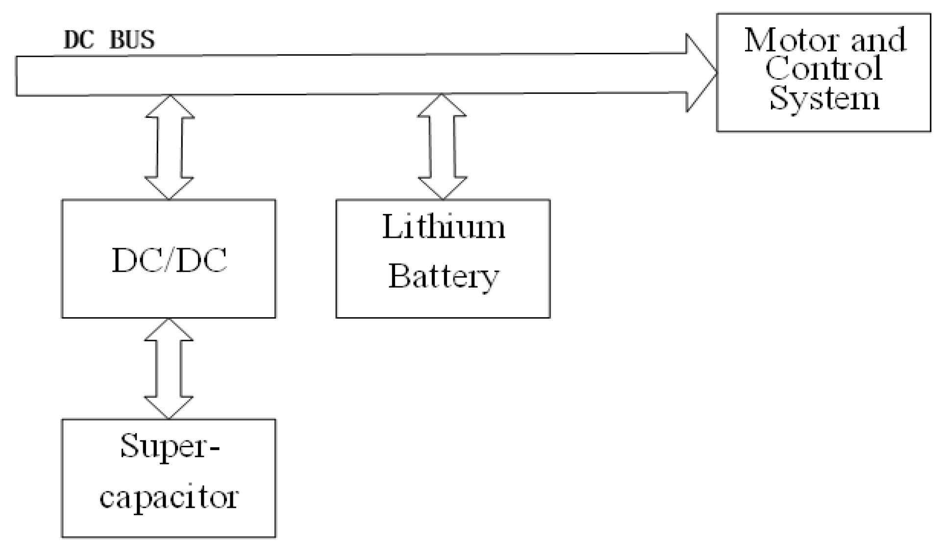
2.1. Overall Structure of Electric Vehicle Power System

The vehicle hybrid system described in this article consists of a lithium battery and a supercapacitor, and its structure is shown in the Figure 1. The lithium battery is directly connected to the DC bus, so the voltage on the DC bus is consistent with the output voltage of the lithium battery. The supercapacitor is connected to the DC bus through bidirectional DC/DC, and the output power of the supercapacitor is controlled by the bidirectional DC/DC.

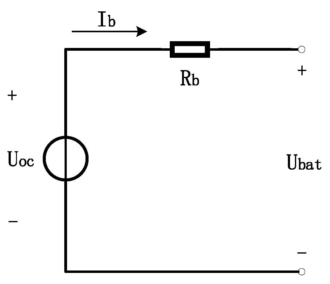
2.2. Lithium Battery Equivalent Circuit and Model Building

Compared with lead–acid and nickel–chromium batteries, lithium batteries have a better energy density and work efficiency, making them the most widely-used batteries in electric vehicles or aircrafts.
In this article, the RC equivalent circuit is chosen to model the lithium battery and the battery equivalent circuit is shown in Figure 2.
Here, U b a t is the open-circuit voltage of the lithium battery, U o c is the ideal voltage source voltage, R b is the internal resistance of the lithium battery, and I b is the charge and discharge current of the lithium battery. According to Kirchhoff’s voltage law, the terminal voltage expression of the lithium battery can be obtained as:
U b a t = U o c I b R int
The calculation expression of the lithium battery power is:
P = U b a t I b
Formula (1) and formula (2) can be combined to solve:
I b = U o c U o c 2 4 P R int 2 R int
The increase in the charging and discharging current of the lithium battery will lead to a decrease in the terminal voltage of the lithium battery, and so the larger of the two solutions can be discarded.
The lithium battery SOC (State of Charge) represents the remaining power of the lithium battery, and its value is related to the maximum discharge capacity Q b a t max and the used power Q b a t u s e d of the lithium battery, which determines the continuous charging and discharging capacity of the lithium battery. The expression of the charge state of the lithium battery S O C b a t is:
S O C b a t = Q b a t max Q b a t u s e d Q max
The calculation formula of the used power Q b a t u s e d of the lithium battery is:
Q b a t u s e d = 0 t η i b d t
where η is the charging and discharging efficiency of the lithium battery and i b is the instantaneous charging and discharging current of the lithium battery.

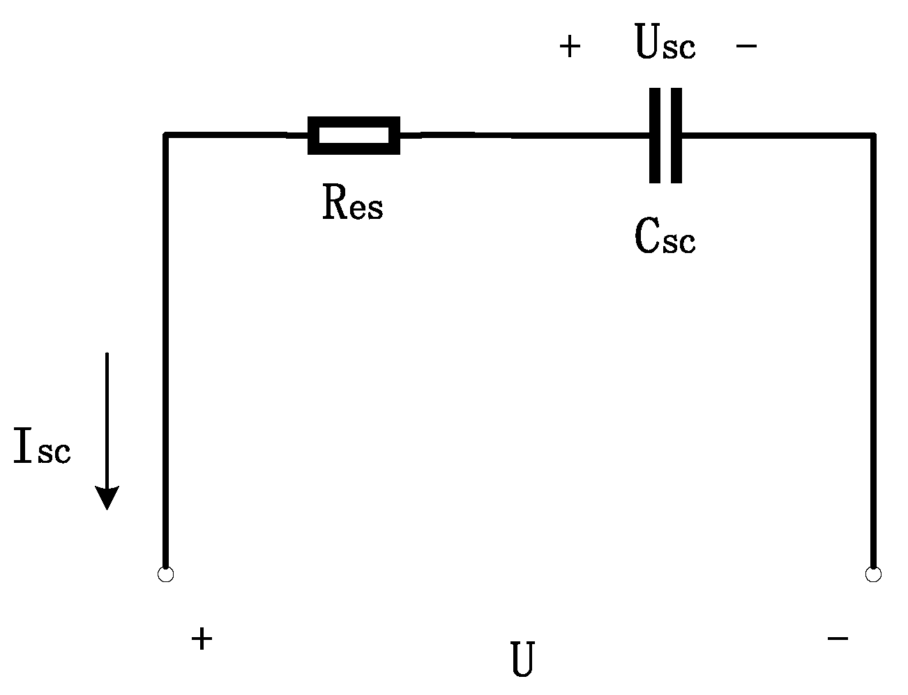
2.3. Supercapacitor Equivalent Circuit and Model Building

The classic RC model of the supercapacitor can reflect the characteristics of the supercapacitor, and it can also be expressed more intuitively and accurately with mathematical formulas. The circuit diagram is shown in the Figure 3.
Here, C s c is the ideal capacitor, U s c is the terminal voltage of the supercapacitor, R e s is the equivalent internal resistance of the supercapacitor, I s c is the charging and discharging current of the supercapacitor, and U is the external load voltage. According to Kirchhoff’s voltage law, the external load voltage U of the supercapacitor can be expressed as:
U = R e s I s c + U s c
The supercapacitor power expression is:
P = U I s c
The supercapacitor charge and discharge current can be solved as (discarding the larger of the two solutions.):
I s c = U s c U s c 2 4 R s c P 2 R s c
The state of charge of the supercapacitor is estimated and calculated by the maximum discharge capacity and the used power of the supercapacitor, and the method is the same as the calculation method for the state of charge of the lithium battery.
The formula for calculating the power used by the supercapacitor is:
Q s c u e d = 0 t i s c d t
where i s c is the instantaneous charge and discharge current of the lithium battery.

3. Optimization Objective Function Design

The power equation of the electric vehicle described in this article is:
P d r i v e ( t ) = v ( t ) ( m v d d t v ( t ) + F a e r o ( t ) + F r o l l ( t ) + F g r a ( t ) )
where P d r i v e ( t ) is the power of the electric vehicle, v ( t ) is the real-time speed of the electric vehicle, m v is the mass of the vehicle, F a e r o ( t ) , F r o l l ( t ) , and F g r a ( t ) are the air resistance, rolling friction, and gravitational component of the ramp rack driving, respectively.
Due to the energy loss, the motor demand power P m provided by the dual-energy hybrid system can be expressed as:
{ P m ( t ) = P d r i v e ( t ) η d r i v e η d r i v e = η t r a η D C / A C η m o t o r
where η d r i v e is the power train efficiency, η t r a is the mechanical drive train efficiency, η D C / A C is the inverter efficiency, and η m o t o r is the motor efficiency.
The required power of the dual-energy hybrid system is provided by the lithium battery and the supercapacitor. The energy distribution of the lithium battery and the supercapacitor can be expressed as:
P m ( t ) = P b a t ( t ) + P s c ( t ) η D C / D C
where P b a t ( t ) is the output power of the lithium battery, P s c ( t ) is the output efficiency of the super capacitor, η D C / D C is the efficiency of bidirectional DC/DC converter.
The purpose of the energy management strategy is to improve the energy utilization efficiency of the dual-energy hybrid power system and the adaptability to the working conditions, and to prevent the lithium battery from being overcharged and over discharged to improve the battery life. The optimization objective function is shown in the following formula (13):
J = t 0 t α ( i b ( t ) 2 R b + i s c ( t ) 2 R s c ) β | Δ i b ( t ) | d t
where i b ( t ) is the output current of the lithium battery, Δ i b ( t ) is the change in the lithium battery current, i s c ( t ) is the output current of the supercapacitor, R b and R s c are the internal resistances of the lithium battery and the supercapacitor, respectively. The optimization objective function consists of the total loss of the system and the rate of change of the output current of the lithium battery. α and β weight factors are used to balance the weight of the two optimization indicators.

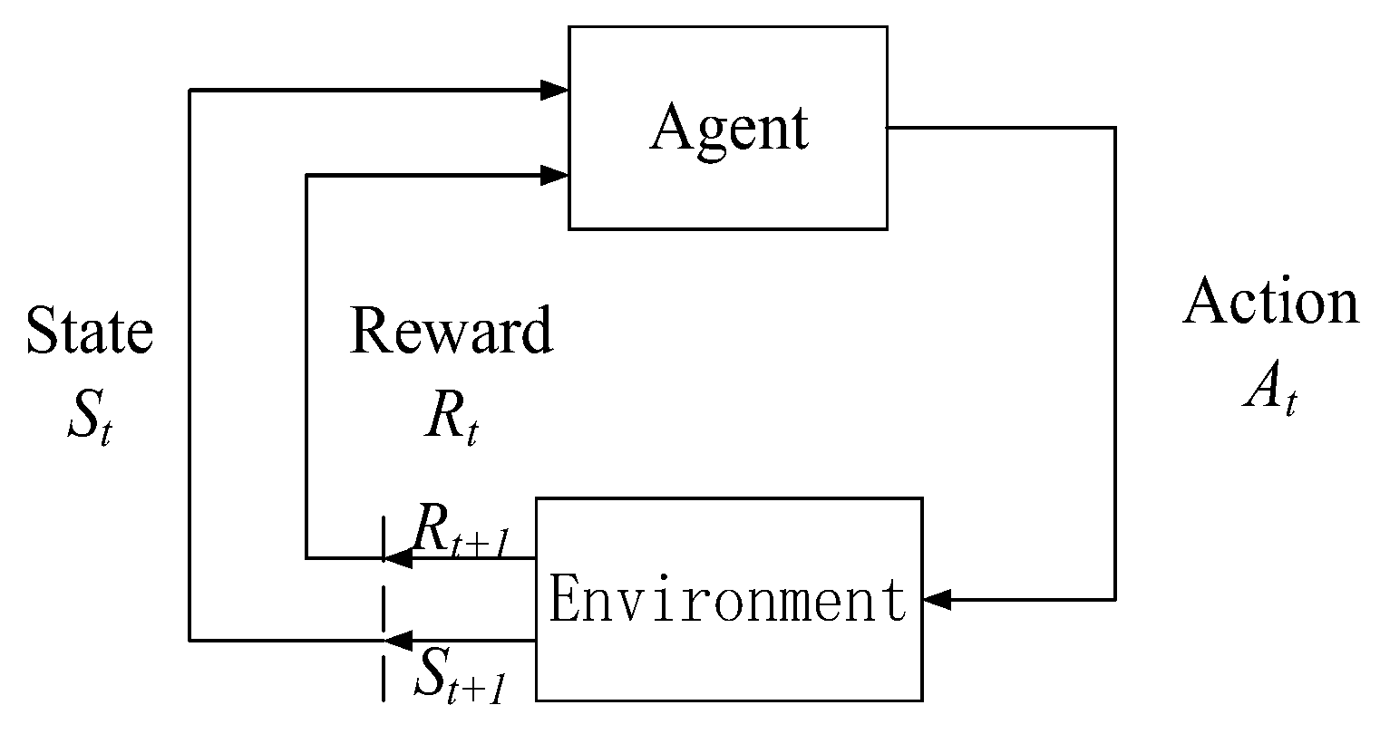
4. Energy Management Strategy Based on Reinforcement Learning Algorithm

This section studies an energy management strategy based on Q-learning. This includes modeling the demand power transfer probability matrix of the hybrid power system, using the Q-learning algorithm to optimize the energy management strategy, and calculating the Pearson correlation coefficient of the demand power transfer matrix for mixed conditions to determine the updated time node of the policy.

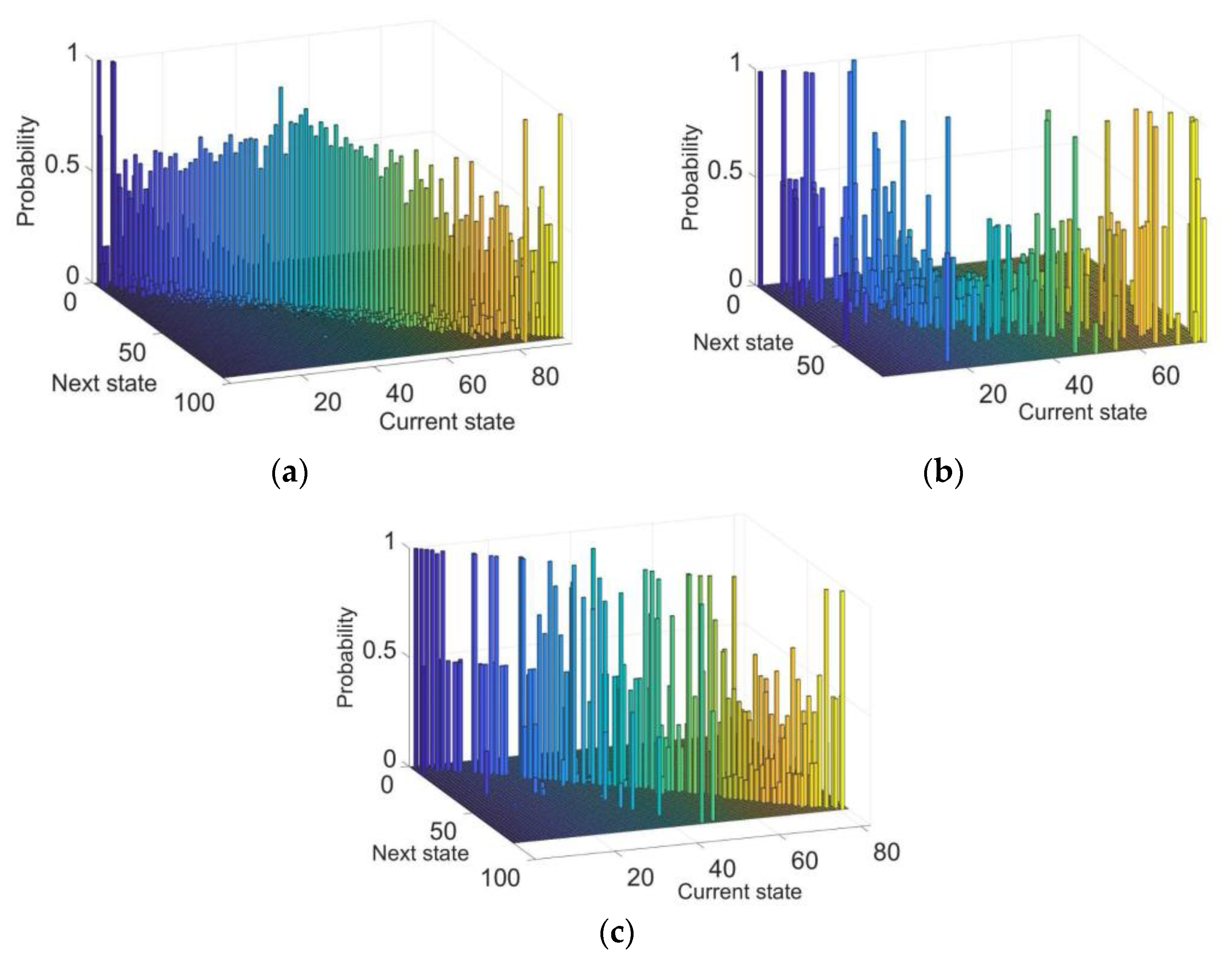
4.1. Transition Probability Matrix

The reinforcement learning Q-learning algorithm uses the grid matrix as a carrier of the action value function. Therefore, a fundamental step in employing this algorithm is to model the demand power. In a working condition, the variation in demand power can be considered as a smooth Markov process, and the demand power state transition probability matrix (TPM) can be calculated by maximum likelihood estimation using the formula:
{ P m = { P m i | i = 1 , , n } φ i j = φ ( P m ( t + 1 ) = P j | P m ( t ) = P i ) = N i j / N i N i = i = 1 n N i j
where P m is the set of demand power levels and the demand power under the working condition is divided into n power levels according to a certain standard. N i j is the number of times that the demand power is transferred from P i to P j under the working condition, and N i is the total number of times that the demand power is transferred from P i under the working condition.
According to the above formula, to solve the Markov model, taking the UDDS (Urban Dynamometer Driving Schedule), NYCC (New York City Cycle), and NEDC (New European Driving Cycle) working conditions as an example, the power transition probability matrix can be obtained, as shown in the Figure 4. It can be seen that the transition probabilities are mostly distributed on the diagonal line, which is due to the fact that the demand power rarely changes abruptly during the driving process, which is in line with the actual driving situation.

4.2. Q-Learning-Based EMS

The algorithm logic of the energy management strategy based on the reinforcement learning Q-learning algorithm is shown in Figure 5.
When using the reinforcement learning method to solve the above optimization problems, the key is to set the input and output and the related parameters of the reinforcement learning algorithm. In the optimization learning of the energy management strategy of the electric vehicle hybrid power system, the required power P m of the hybrid power system and the charge state S O C b a t of the lithium battery are used as the input state quantities of the reinforcement learning problem, and the output power P s c of the supercapacitor is used as the action output of the reinforcement learning problem. The agent of reinforcement learning chooses the amount of output action based on the value of the reward return. In this optimization problem, the state s , the action a , and the reward r are set as:
{ s S = { v ( t ) , P m ( t ) , S O C s c } a A = { P s c ( t ) } r R = { α ( i b ( t ) 2 R b + i s ( t ) 2 R s c ) β | Δ i b ( t ) | }
where s represents the state of the electric vehicle at a time when driving, including the required power of the hybrid system P m ( t ) , the real-time speed of the electric vehicle v ( t ) , and the current charge state of the supercapacitor S O C s c ( t ) . a represents the next action of the hybrid system when the electric vehicle is in state s , that is, controlling the bidirectional DC/DC converter to adjust the energy distribution between the lithium battery and the supercapacitor, and set the output power P s c ( t ) of the super capacitor as the action amount of the system. r represents the reward and return obtained by the system after the electric vehicle performs action a , when it is in state s , which is related to the loss of the lithium battery and super capacitor and the change of the lithium battery current; α is the penalty weight factor ( α > 0 ) for the loss of the lithium batteries and supercapacitors, and β is the penalty weight factor for the change of the lithium battery current ( β > 0 ); r is a non-positive number. The larger the reward value, the better the energy distribution of the hybrid system. By adjusting the values of parameters α and β , the energy management strategy can balance the power output of the lithium batteries and supercapacitors.
During the training process of the agent, the following constraints were also observed:
{ I b min < i b ( t ) < I b max S O C b min < S O C b ( t ) < S O C b max S O C s c min < S O C s c ( t ) < S O C s c max ,
These are to ensure that the charge and discharge current of the lithium battery is maintained within the appropriate charge and discharge current range, and the lithium battery and supercapacitor should be careful not to overcharge or over-discharge during system operation.
The energy management strategy based on a reinforcement learning algorithm is a mapping function from state quantities to action quantities π : S A . This means that in a given state s t , according to the energy management strategy, the next action can be determined as a t = π ( s t ) . For each state s t , the value function is defined as the mathematical expectation of the cumulative reward:
V π ( s ) = E { k = 0 γ k r ( t + k ) } ,
where γ is the discount factor and γ ( 0 , 1 ) is to ensure the convergence of the algorithm. E is the cumulative expected value of the feedback quantity of the reward function and the value function V π ( s ) satisfies the Bellman equation.
V π ( s ) = r ( s ) + γ s S φ s a ( s ) V π ( s )
where r ( s ) represents the immediate reward in the current state s . s represents the next state the system may be in after the agent is in state s and performs action a . φ s a ( s ) represents the probability that the system will be in state s after the agent is in state s and performs action a .
In order to solve the optimal value function for V π ( s ) , that is, to solve the optimal control strategy π ( s ) in the current state s :
V * ( s ) = r ( s ) + max a A γ s S φ s a ( s ) V * ( s )
The above optimal solution can be transformed into a Q function.:
V * ( s ) = max π Q ( s , a )
Q ( s , a ) = r ( s , a ) + γ s S φ s a ( s ) Q ( s , a )
where Q ( s , a ) represents the cumulative discount return obtained after performing action a in the current state s .
By optimizing the iterative Q function to maximize the cumulative discounted return, the update rule for Q-learning reinforcement learning can be expressed as:
Q ( s , a ) Q ( s , a ) + η ( r + γ max a Q ( s , a ) Q ( s , a ) )
where η [ 0 , 1 ] is the learning rate and its value is positively related to the convergence rate of reinforcement learning.

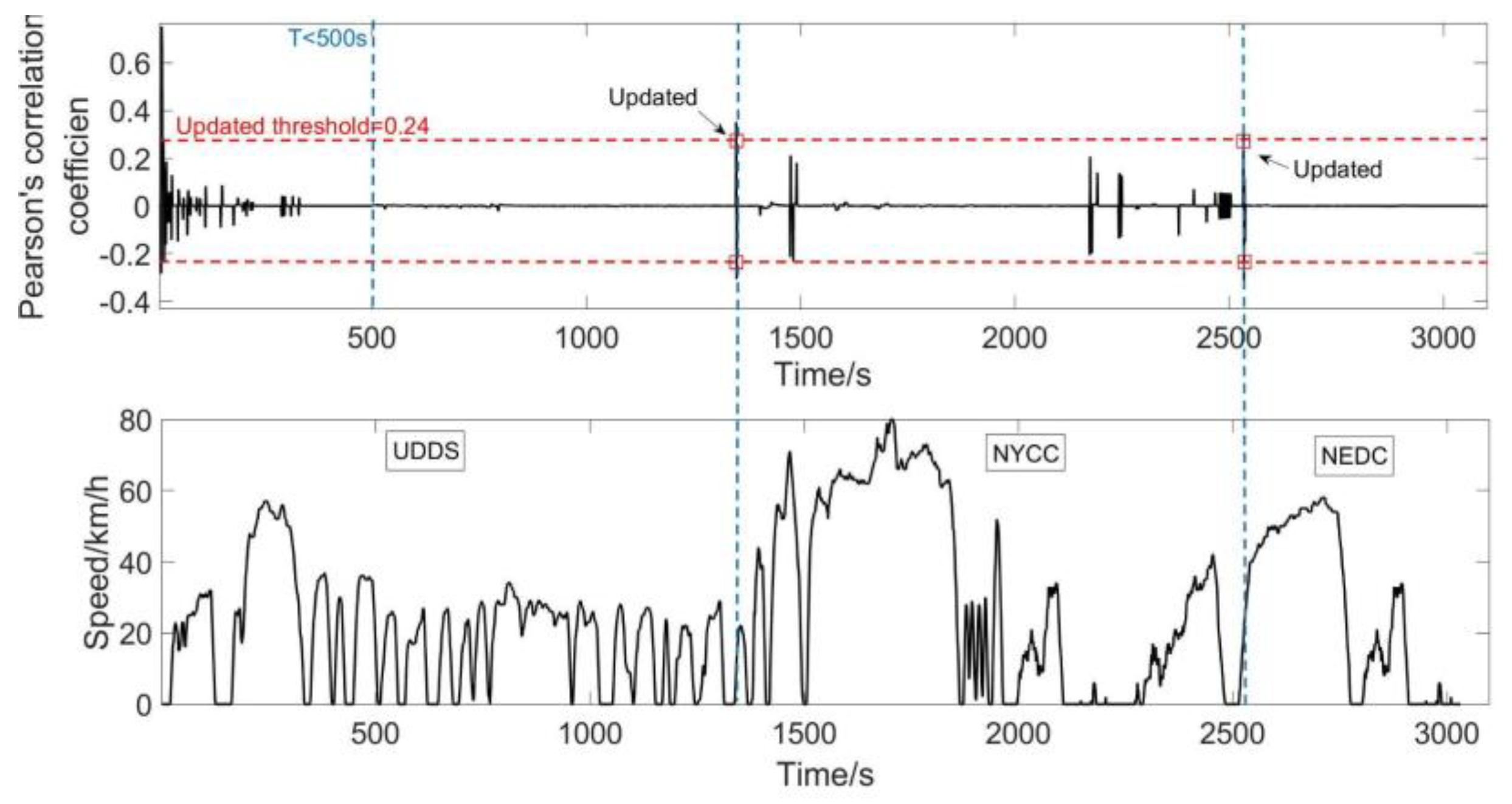
4.3. Online Update of the Demand Power State Transition Probability Matrix

The comparison of the probability transition probability matrices under different working conditions requires a criterion to measure the difference between two probability transition probability matrices. This article introduces the Pearson similarity coefficient ρ as a reference.
ρ = cov ( { φ } { φ } ) D ( { φ } ) D ( { φ } ) = φ i j φ i j φ i j φ i j N ( φ i j 2 ( φ i j ) 2 N ) ( φ i j 2 ( φ i j ) 2 N )
where P is the demand power probability transition matrix calculated according to the previous working conditions, and P* is the demand power transition probability matrix calculated based on the new working conditions.
By calculating the Pearson similarity coefficient between the two probability transition probability matrices, the difference between the two working conditions represented by them is judged as follows: Set a suitable reference threshold λ ( 0 , 1 ) and compare the absolute value of ρ with λ . If | ρ | > λ , take the new probability transition probability matrix as the state, relearn and optimize a better energy management strategy, and apply it to the actual operation of the vehicle. If | ρ | λ , it means that the original energy management strategy is still applicable to the new working conditions and the vehicle continues to operate with this energy management strategy.

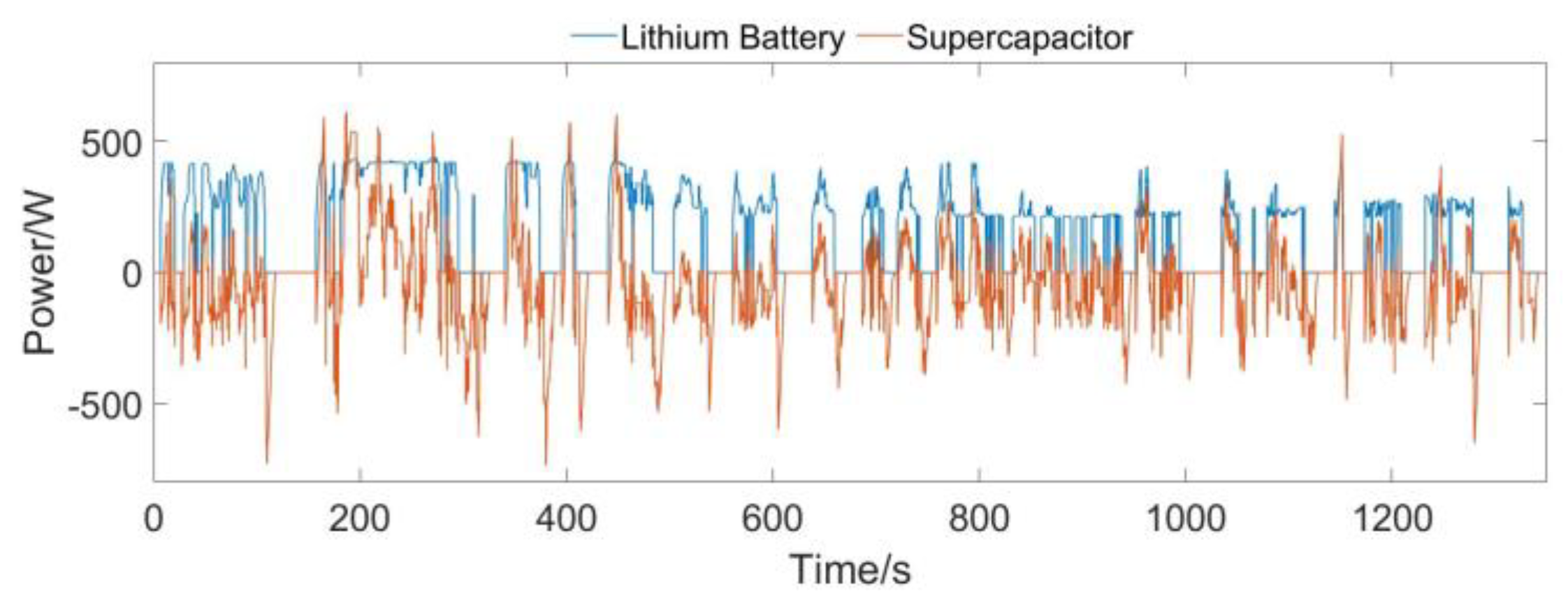
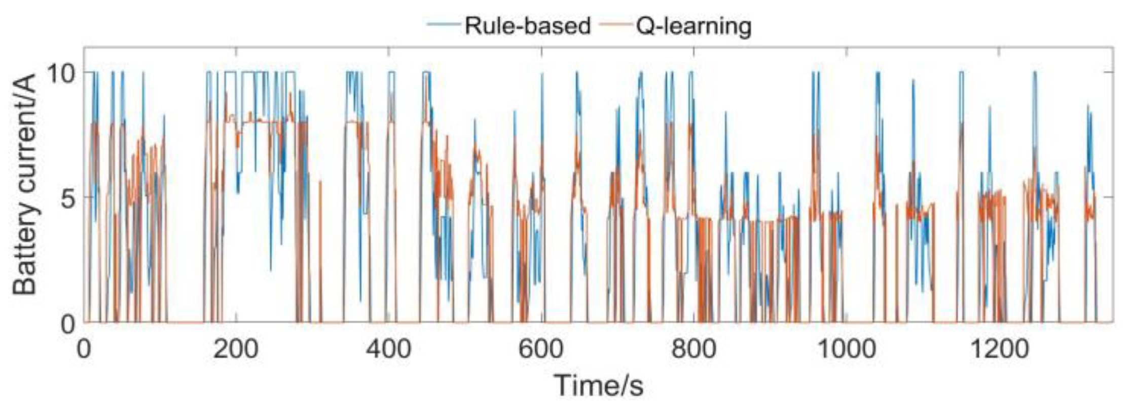
5. Simulation and Analysis of Results

Table 1 shows the system parameter values of the main components of the hybrid power system.
Figure 6 shows the simulation results of the hybrid power system using the energy management strategy based on Q-learning under UDDS conditions. The output current of the lithium battery under the Q-learning energy management strategy is compared with the output current of the lithium battery controlled by the rule based on Q-learning, as shown in Figure 7. When the energy management strategy based on Q-learning is used for operating conditions, the state of charge of the lithium battery of the dual-energy hybrid power system decreases slowly and fluctuates less.
After running a UDDS case, the lithium battery loss was 0.460 W/h under the energy management strategy based on the logic threshold. The lithium battery current conversion rate Σ|Δib|2 was 1.6755 × 10⁴. The lithium battery loss under the energy management strategy based on Q-learning was 0.458 W/h and the lithium battery current conversion rate was 1.0862 × 10⁴. They were reduced by 0.43% and 35.17%, respectively. It shows that under the energy management strategy based on Q-learning, the hybrid mode can reduce the loss of the lithium battery and effectively reduce the change of lithium battery current, reducing the life loss caused by the change of the lithium battery current.
The change of driving conditions was identified by calculating the Pearson correlation coefficient between the TPMs. The Pearson correlation coefficient of the transition probability matrix of the hybrid system operating under the combined conditions of the UDDS, NYCC, and NEDC is shown in Figure 8. Comparing the change value of the absolute value of the Pearson correlation coefficient with the reference threshold value, we can intuitively see the degree of change of the working condition, and obtain the updated point through the appropriate reference threshold value. It can be seen from the figure that the working condition update nodes are 1346 s and 2569 s, and the working condition update points obtained from the Pearson correlation coefficient are 1377 s and 2540 s; these calculated update points are very close to the working condition change points.

6. Conclusions

In this article, an energy management strategy based on Q-learning is designed for a dual-energy electric vehicle hybrid system. Compared with the rule-based energy management strategy in UDDS, this strategy reduces the loss and the current conversion rate of a lithium battery by 0.43% and 35.17%, respectively. The effectiveness of the energy management strategy based on Q-learning is shown, and the determination of the updated point of the energy management control quantity was realized through the change of the transition probability matrix under the mixed working conditions. The next work includes studying the real-time control of the reinforcement learning strategies on HEV, and using deep reinforcement learning to realize the energy management strategies of electric vehicle hybrid systems in a continuous state space and action space.

Author Contributions

Conceptualization, G.X.; validation, Y.C. and G.X.; data curation, Y.C.; writing—original draft preparation, Y.C.; writing—review and editing, G.X. and Y.C.; supervision, Q.C. All authors have read and agreed to the published version of the manuscript.

Funding

National Natural Science Foundation of China under grant 62173264.

Acknowledgments

The authors would like to express gratitude to all those who helped us during the writing of this article.

Conflicts of Interest

The authors declare no conflict of interest.

References

  1. Sulaiman, N.; Hannan, M.; Mohamed, A.; Majlan, E.; Daud, W.W. A review on energy management system for fuel cell hybrid electric vehicle: Issues and challenges. Renew. Sustain. Energy Rev. 2015, 52, 802–814. [Google Scholar] [CrossRef]
  2. Du, G.; Zou, Y.; Zhang, X.; Kong, Z.; Wu, J.; He, D. Intelligent energy management for hybrid electric tracked vehicles using online reinforcement learning. Appl. Energy 2019, 251, 113388. [Google Scholar] [CrossRef]
  3. Busoniu, L.; Babuska, R.; De Schutter, B. A Comprehensive Survey of Multiagent Reinforcement Learning. IEEE Trans. Syst. 2008, 38, 156–172. [Google Scholar] [CrossRef] [Green Version]
  4. Lin, X.; Wang, Y.; Bogdan, P.; Chang, N.; Pedram, M. Reinforcement learning based power management for hybrid electric vehicles. In Proceedings of the 2014 IEEE/ACM International Conference on Computer-Aided Design (ICCAD), San Jose, CA, USA, 2–6 November 2014; pp. 33–38. [Google Scholar] [CrossRef]
  5. Liu, T.; Zou, Y.; Liu, D.; Sun, F. Reinforcement Learning–Based Energy Management Strategy for a Hybrid Electric Tracked Vehicle. Energies 2015, 8, 7243–7260. [Google Scholar] [CrossRef] [Green Version]
  6. Wu, J.; He, H.; Peng, J.; Li, Y.; Li, Z. Continuous reinforcement learning of energy management with deep Q network for a power split hybrid electric bus. Appl. Energy 2018, 222, 799–811. [Google Scholar] [CrossRef]
  7. Lin, X.; Xia, Y. Energy management control strategy for plug-in fuel cell electric vehicle based on reinforcement learning algorithm. Chin. J. Eng. 2019, 41, 1332–1341. [Google Scholar]
  8. Han, X.; He, H.; Wu, J.; Peng, J.; Li, Y. Energy management based on reinforcement learning with double deep Q-learning for a hybrid electric tracked vehicle. Appl. Energy 2019, 254, 113708. [Google Scholar] [CrossRef]
  9. Li, Y.; He, H.; Peng, J.; Wang, H. Deep Reinforcement Learning-Based Energy Management for a Series Hybrid Electric Vehicle Enabled by History Cumulative Trip Information. IEEE Trans. Veh. Technol. 2019, 68, 7416–7430. [Google Scholar] [CrossRef]
  10. Liu, T.; Wang, B.; Yang, C. Online Markov Chain-based energy management for a hybrid tracked vehicle with speedy Q-learning. Energy 2018, 160, 544–555. [Google Scholar] [CrossRef]
  11. Xiong, R.; Cao, J.; Yu, Q. Reinforcement learning-based real-time power management for hybrid energy storage system in the plug-in hybrid electric vehicle. Appl. Energy 2018, 211, 538–548. [Google Scholar] [CrossRef]
  12. Liu, T.; Zou, Y.; Liu, D.; Sun, F. Reinforcement Learning of Adaptive Energy Management With Transition Probability for a Hybrid Electric Tracked Vehicle. IEEE Trans. Ind. Electron. 2015, 62, 7837–7846. [Google Scholar] [CrossRef]
  13. Liu, T.; Tang, X.; Hu, X.; Tan, W.; Zhang, J. Human-like Energy Management Based on Deep Reinforcement Learning and Historical Driving Experiences. arXiv 2020, arXiv:2007.10126. [Google Scholar]
  14. Partridge, P.W.J.; Bucknall, R. Cost-effective reinforcement learning energy management for plug-in hybrid fuel cell and battery ships. Appl. Energy 2020, 275, 115258. [Google Scholar]
  15. Hasanvand, S.; Rafiei Foroushani, M.; Gheisarnejad, M.; Khooban, M.H. Reliable Power Scheduling of an Emission-Free Ship: Multi-Objective Deep Rein-forcement Learning. IEEE Trans. Transp. Electrif. 2020, 6, 832–843. [Google Scholar] [CrossRef]
  16. Qi, X.; Wu, G.; Boriboonsomsin, K.; Barth, M.J.; Gonder, J. Data-driven reinforcement learning–based real-time energy management system for plug-in hybrid electric vehicles. J. Transp. Res. Board 2015, 2572, 1–8. [Google Scholar] [CrossRef] [Green Version]
  17. Lin, X.; Zhou, B.; Xia, Y. Online Recursive Power Management Strategy based on the Reinforcement Learning Algorithm with Cosine Similarity and a Forgetting Factor. IEEE Trans. Ind. Electron. 2020, 68, 5013–5023. [Google Scholar] [CrossRef]
  18. Xiong, R.; Chen, H.; Wang, C.; Sun, F. Towards a smarter hybrid energy storage system based on battery and ultracapacitor-A critical review on topology and energy management. J. Clean. Prod. 2018, 202, 1228–1240. [Google Scholar] [CrossRef]
  19. Meng, X.; Li, Q.; Zhang, G.; Wang, X.; Chen, W. Double Q-learning-based Energy Management Strategy for Overall Energy Consumption Optimization of Fuel Cell/Battery Vehicle. In Proceedings of the 2021 IEEE Transportation Electrification Conference & Expo (ITEC), Chicago, IL, USA, 21–25 June 2021; pp. 1–6. [Google Scholar] [CrossRef]
  20. Zhang, G.; Li, Q.; Chen, W.; Meng, X.; Deng, H. A coupled power-voltage equilibrium strategy based on droop control for fuel cell/battery/supercapacitor hybrid tramway. Int. J. Hydrog. Energy 2019, 44, 19370–19383. [Google Scholar] [CrossRef]
Figure 1. Electric vehicle hybrid system.
Electronics 11 01933 g001
Figure 2. Lithium battery RC equivalent circuit.
Electronics 11 01933 g002
Figure 3. Supercapacitor RC Equivalent Circuit.
Electronics 11 01933 g003
Figure 4. (a) TPM of UDDS. (b) TPM of NYCC. (c) TPM of NEDC.
Electronics 11 01933 g004
Figure 5. Q-learning logic block diagram.
Electronics 11 01933 g005
Figure 6. Output power under Q-learning strategy.
Electronics 11 01933 g006
Figure 7. Output current comparison.
Electronics 11 01933 g007
Figure 8. Energy management strategy update time point.
Electronics 11 01933 g008
Table 1. System parameter values of the main components.
ComponentParameterValue
Lithium batteryRated Capacity/Ah40
Rated voltage/V48
Internal resistance/mΩ12
SupercapacitorRated Capacity/F165
Rated voltage/V48.6
Internal resistance/mΩ6
Publisher’s Note: MDPI stays neutral with regard to jurisdictional claims in published maps and institutional affiliations.

