Article

A Novel SIW Leaky-Wave Antenna for Continuous Beam Scanning from Backward to Forward

by
Saeed Kamalzadeh
and
Mohammad Soleimani
*
School of Electrical Engineering, Iran University of Science and Technology, Tehran 13114-16846, Iran
*
Author to whom correspondence should be addressed.
Electronics 2022, 11(12), 1804; https://doi.org/10.3390/electronics11121804
Submission received: 8 April 2022 / Revised: 8 May 2022 / Accepted: 10 May 2022 / Published: 7 June 2022
(This article belongs to the Section Microwave and Wireless Communications)

Abstract

:
A novel, periodic, leaky-wave array antenna using substrate-integrated waveguide (SIW) technology is proposed for continuous beam scanning applications. For this purpose, a periodic structure with the ability to radiate from backward to forward is proposed. The unit cell of this periodic structure includes a longitudinal slot and an H-plane discontinuity. The H-plane step discontinuity is suggested to suppress the open stopband (OSB) and enable continuous beam scanning from backward to forward through the broadside. The impedance matching technique is used to suppress the open stopband. In contrast to phased array antennas, this form of antenna is distinguished by its ability to scan without requiring a complex feeding network. These antennas are used for different factors such as scanning the beam, determining the direction of arrival, avoiding collisions, indoor communications, etc. A prototype of the proposed antenna was fabricated for experimental characterization. The overall physical dimensions of the fabricated antenna are 7.9 mm × 128 mm. The results demonstrate that an adequate level of agreement between measurement and simulation is satisfactory. The results indicate that the suggested antenna can scan continuously in the frequency range of 14.5 to 22.5 GHz between −60 and +57.5 degrees through broadside with a maximum gain of 16 dBi and radiation efficiency of 71%.

1. Introduction

Beam-scanning antennas have widely been used in radar systems, modern wireless communication, mobile communication, and satellite communication. Beam-scanning antennas can be realized mechanically, electrically, and frequency scanning. Servo motors and rotary joints are required for mechanical beam scanning [1]. These systems are massive and bulky, and the implementation process is costly and complicated. The realization of the electrical beam scanning requires phase shifters and switches [2]. Since these components are active and need the driving supply, the power consumption of the system is significantly increased. In some papers, ferrite has been used to make beam scanning possible. However, because ferrite depends on frequency, it has limited bandwidth [3,4].
The leaky-wave antenna (LWA) is one of the most intriguing mechanisms for providing frequency beam-scanning capability. These structures are commonly used in engineering electromagnetics because of their simple and lightweight structure, high gain, and beam-scanning capability. For example, LWAs are widely used in automotive radars [5], human range-azimuth tracking systems [6], estimating the direction of arrival (DoA) [7], real-time spectrum analysis [8], and navigation systems [9].
LWA consists of a transmission line inspired by the radiating elements. Several types of transmission lines exist; microstrip lines [10,11,12], dielectric waveguides (NRD) [13,14], rectangular waveguides [15], and substrate-integrated waveguides (SIW) are some of the examples [16,17] recommended for implementing LWA. Among them, SIW is a proper alternative to the classic hollow waveguide. Unlike metallic waveguide LWAs, which are bulky and expensive, SIW LWAs are inexpensive, with low profiles, and simple to fabricate. The SIW LWA integrates easily with other planar circuits. The substrate’s undesired radiation in the microstrip LWA is eliminated in SIW LWA [18]. Additionally, the SIW LWA has a substantially higher power handling capacity than the microstrip-line-based one. As a result, the SIW LWA is a lightweight and planar choice for applications requiring high power-handling capability. Due to the aforementioned benefits, SIW-based structures have become one of the most intriguing topics in the disciplines of LWA in recent years. SIW LWAs are classified into four types: uniform [16,17], quasi-uniform [19,20,21], composite right/left-handed (CRLH) [22,23], and periodic [24,25].
The radiating element in the first type of SIW LWA is evenly dispersed along the path of wave propagation within the substrate [16,17]. The quasi-uniform SIW LWA is a periodic structure with a spacing interval that is less than the wavelength [19,20,21]. These two classes of SIW LWA operate on the fundamental space harmonic, on which fast waves propagate inside the substrate. These structures can be used for beam scanning in the forward quadrant space while avoiding broadside radiation. The beam-scanning range is one of the most essential characteristics of LWAs. Beam scanning from backward to forward is necessary for many applications. Unlike the two previous kinds of SIW LWAs, the CRLH and periodic LWAs can enable backward-to-forward beam scanning [22,23].
The open stopband (OSB) causes gain deterioration toward the broadside direction, which is one of the primary concerns with the CRLH and periodic LWAs [22,23,24]. Due to the fact that the reflected waves from each unit cell are in phase at the broadside frequency, electromagnetic energy cannot be transmitted from the antenna to the surrounding medium, resulting in the open stopband. In a CRLH LWA, the balanced transmission line must be employed to avoid the open stopband. One of the key disadvantages of the CRLH LWA is that its random behavior at the cutoff frequency is highly dispersed. Several strategies including impedance matching [26,27,28,29,30], reflection cancellation [31], and the use of an asymmetric structure [31,32] are discussed for suppressing periodic LWAs with an open stopband.
In this paper, a novel unit cell is proposed for open stopband-suppressing of the SIW periodic LWA based on the impedance matching technique. The proposed unit cell consists of the longitudinal slot and the rectangular-shaped H-plane discontinuity. The rectangular-shaped H-plane discontinuity is one of the most commonly utilized waveguide junctions in waveguide filters and multiplexers design, which exhibits inductive behavior. The inductive nature of the rectangular-shaped H-plane discontinuity is used to compensate for the capacitive effect of the longitude slot and provide proper impedance matching. The circuit equivalent and dispersion analysis are performed to verify the validity of the proposed unit cell in providing the impedance matching and suppressing the OSB. For the experimental verification, a prototype of the proposed LWA array is fabricated. The experimental results confirm that an adequate level of agreement exists between measurement and simulation. Results show that the proposed antenna provides continuous beam scanning capability between ranges of −60 and +57.5, involving broadside direction with a maximum gain of 16 dBi.

2. Antenna Design

The proposed leaky-wave antenna is constructed using substrate-integrated technology. The copper-cladding layers are placed at the top and bottom of SIW. The SIW technology can provide a high power-handling capability, low return loss, low manufacturing cost, and high-density integration. The two rows of metallic vias, which are placed along the wave propagation path, play similar roles to the perfect conducting wall of the waveguide. The thickness and width of the SIW are h and w, respectively. The period of the vias is s, and the diameter of the metallic vias is d. A 0.813 mm thick RO4003 laminate with a relative permittivity of εr = 3.55 and tanσ = 0.0027 is used as the substrate. The length of each unit cell as a period of the full array antenna is p.
As shown in Figure 1, the longitudinal slots are placed on the two opposite sides of the top plate of the array antenna. This configuration increases the number of slots as radiating elements and consequently enhances radiation performance and maximum gain. In addition, for the array in which the radiating elements are placed on one side of the top wall, the cross-polarization level is high due to the coupling effect. The proposed configuration for the array antenna can resolve this problem and significantly decrease the cross-polarization level.
For a periodic LWA, the direction of the main beam is related to the phase constant of the nth space harmonic in the following way:
θ m a i n b e a m n sin 1 ( β n k 0 )
β n = β 0 + 2 n π p
where β0 is the propagation constant of the dominant TE10 mode within SIW, k0 is the free-space wavenumber, and p is the period of the array. It can be clearly seen that the direction of the main beam is changed by the frequency, which can provide the frequency beam-scanning capability. The proposed leaky-wave antenna setup is based on the −1st space harmonic.

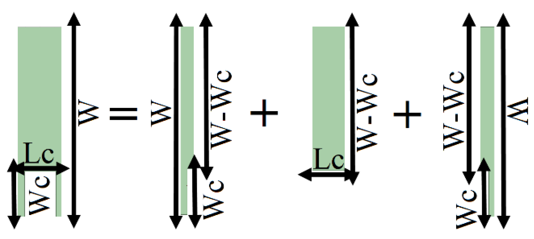
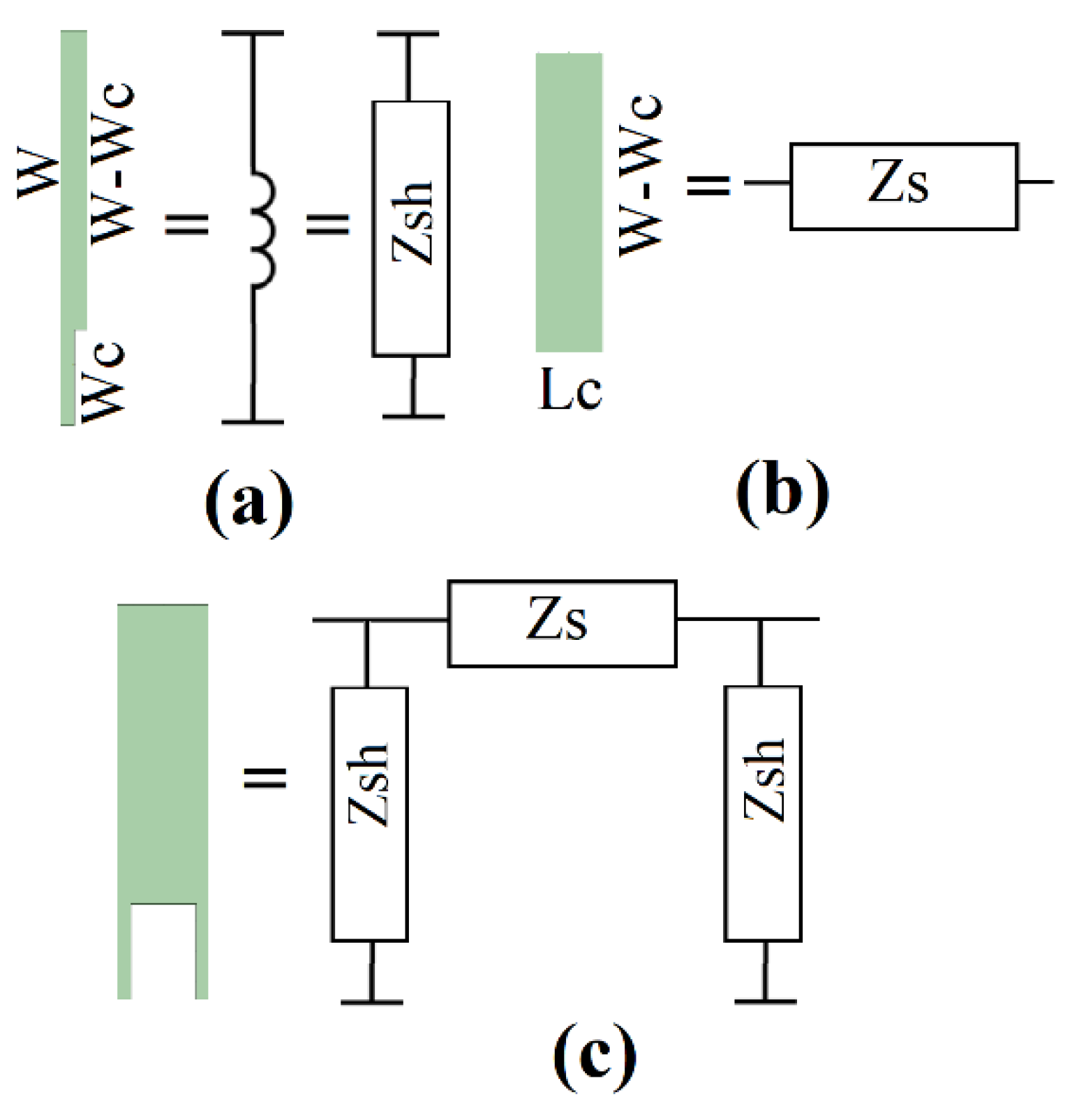
2.1. Unit Cell in Ideal Waveguide

As shown in Figure 1, the unit cell of the proposed LWA consists of a longitudinal slot and rectangular-shaped H-plane discontinuity. To perturb the surface current for radiation, the longitudinal slots are placed offset from the center and on top of the metallic plate of SIW. In this paper, the length of the slot and distance from the centerline were selected to provide a longitudinal slot with capacitive behavior.
In [33], metallic via has been used to compensate for the capacitive effect of the longitudinal slot and provide impedance matching for OSB suppression. In a similar way to the cylindrical post, which is used in waveguide structures such as filters, the metallic via effectively behaves as an inductance. The rectangular-shaped H-plane discontinuity is another mechanism that can provide an inductive behavior in the waveguide [34,35]. Iris is one of the application examples for the H-plane discontinuity, which is widely used in waveguide filters.
It is possible that the rectangular-shaped H-plane discontinuity, which is realized by using metalized vias in the SIW technology, is similar to the method presented in [33]. As presented earlier, in the proposed method, rectangular-shaped H-plane discontinuity is used. In contrast, the technique presented in [33] is based on similarities between metallic-via cylindrical posts in providing an inductive effect. For revealing this difference, the proposed design for the unit cell is verified with the ideal waveguide technology, and then the results are presented for the SIW structure.
Consider an ideal waveguide with the longitude slot placed at the top plate, as shown in Figure 2. The waveguide is filled by the dielectric substrate with a relative permittivity of εr = 3.55 and tanσ = 0.0027. The height and width of the waveguide are W = 6.6 mm and h = 0.813 mm. All numerical simulations for the ideal waveguide are performed for the mentioned specifications. The numerical simulation is performed using the commercial EM software of ANSYS Electronics Desktop (HFSS V.15.0.2., Canonsburg, PA, USA) The length and width of the slot are Ls = 5.1 mm and Ws = 0.4 mm. The offset of the longitudinal slots from the centerline of the top plate is Lofs = 2 mm. The period of the unit cell must be considered to be p = 11.9 mm to provide the broadside frequency at 18 GHz based on Equations (1) and (2). The longitude slot is modeled with T-network, as shown in Figure 3 [36]. The series and shunt normalized impedance in T-network is calculated by formulations presented in [36] and is shown in Figure 4.
It can easily be seen that the series impedance and the real part of the shunt impedance are very small and can be neglected in the equivalent circuit. Therefore, the longitude slot can be modeled by shunt capacitance.
As shown in Figure 5, the rectangular-shaped H-plane discontinuity can be decomposed to the two H-plane steps with a width of Wc and the waveguide section with a length of Lc and width of W-Wc.
The H-plane step discontinuity can be modeled using shunt inductance [37]. The waveguide section is modeled using series impedance. The circuit equivalent of the rectangular-shaped H-plane discontinuity is represented based on π-networks, as shown in Figure 6. The series and shunt impedance values of the circuit equivalent are obtained as follows:
Z S = ( 1 + S 11 ) 2 ( S 21 ) 2 2 S 21
Z s h = ( 1 + S 11 ) 2 ( S 21 ) 2 ( 1 S 21 ) 2 ( S 11 ) 2
The Π-network equivalent circuit for waveguide with rectangular shaped H-plane discontinuity is shown in Figure 7.
The S-parameters of the rectangular-shaped H-plane discontinuity are calculated using numerical simulation. The width and length of the discontinuity are assumed to be Wc = 1.4 mm and Lc = 1.1 mm, respectively. ANSYS Electronics Desktop is used for numerical simulation. The S-parameters are used in Equations (3) and (4) to calculate the series and shunt impedance values in the equivalent circuit. The real and imaginary parts of the series and shunt impedance in π-network equivalent circuit are shown in Figure 8. It can easily be seen that the real part of the Zsh and the series impedance of Zs are smaller than the imaginary part of Zsh. The rectangular-shaped H-plane discontinuity can be modeled using shunt inductance, as shown in Figure 9.
Figure 10 shows the variation in the shunt reactance regarding the thickness and width of the discontinuity. Results confirm that the inductive effect of the proposed discontinuity is varied by thickness and width, which can be used for tunning in the impedance matching process.
According to the presented circuit equivalent for the longitude slot and rectangular-shaped H-plane discontinuity, our proposed unit cell can be equivalently modeled with shunt susceptance, as shown in Figure 11. The imaginary parts of the shunt susceptance for the longitude slot, rectangular-shaped H-plane discontinuity, and proposed unit cell are shown in Figure 12. Results confirm that the rectangular-shaped H-plane compensates for the capacitive effect of the longitudinal slot. The combination of the longitude slot and rectangular-shaped H-plane discontinuity act as an open circuit and provides proper impedance matching in the proposed unit cell.

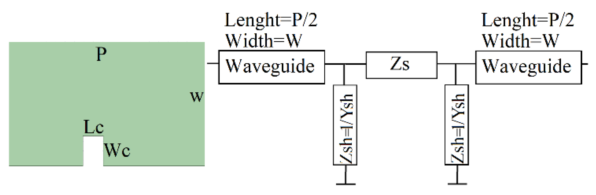
2.2. Unit Cell in Ideal Waveguide

In this section, the performance of the proposed unit cell is investigated for realization in the SIW technology. In order to investigate the OSB suppression, the circuit equivalent and dispersion analysis must be performed for the unit cell. The width of the equivalent substrate-integrated waveguide corresponding to the ideal waveguide is obtained as follows:
W S I W = W W G + 4 R d 2 10 W W 4 R d 2 0.95 S
The dimensions of the unit cell in the SIW technology, which is used in an array configuration, are presented in Table 1.
The schematic of the longitude slot, rectangular-shaped h-plane discontinuity, and the proposed unit cell in the SIW technology are shown in Figure 13. The imaginary part of the shunt admittance in the circuit equivalent for mentioned unit cells is presented in Figure 14. It can easily be seen that the effective nature of the longitude slot is compensated by rectangular discontinuity, and the impedance matching is provided in the proposed unit cell.
In order to investigate the OSB suppression, a dispersion analysis must be performed in the following. The effective attenuation constant αeff and the effective phase constant βeff can be calculated using the S-parameters as follows [38]:
α e f f = 1 p Im [ cos 1 ( A + D 2 ) ]
| β e f f | = 1 p Re [ cos 1 ( A + D 2 ) ]
where A and D are the elements of the ABCD matrix of the unit cell, which can be calculated with Equation (2) using the classic conversion formulas.
Figure 15 shows the effective phase constant and the attenuation constant for a unit cell with a longitudinal slot. It can easily be seen that the attenuation constant is maximum at the broadside frequency, which can result in gain deterioration occurring in OSB. Figure 16 depicts the effective phase constant and attenuation constant of the proposed unit cell, which consists of a longitudinal slot and a step discontinuity. Results confirm that the effective attenuation constant is approximately near zero and that OSB suppression is achieved. Moreover, the dispersion diagram confirms that the slope of the effective phase constant versus frequency continuously varies from negative to positive, covering the zero value at broadside frequency. Therefore, the LWA consisting of an array of the proposed unit cells can provide the continuous beam-frequency beam scanning from backward to forward through the broadside.

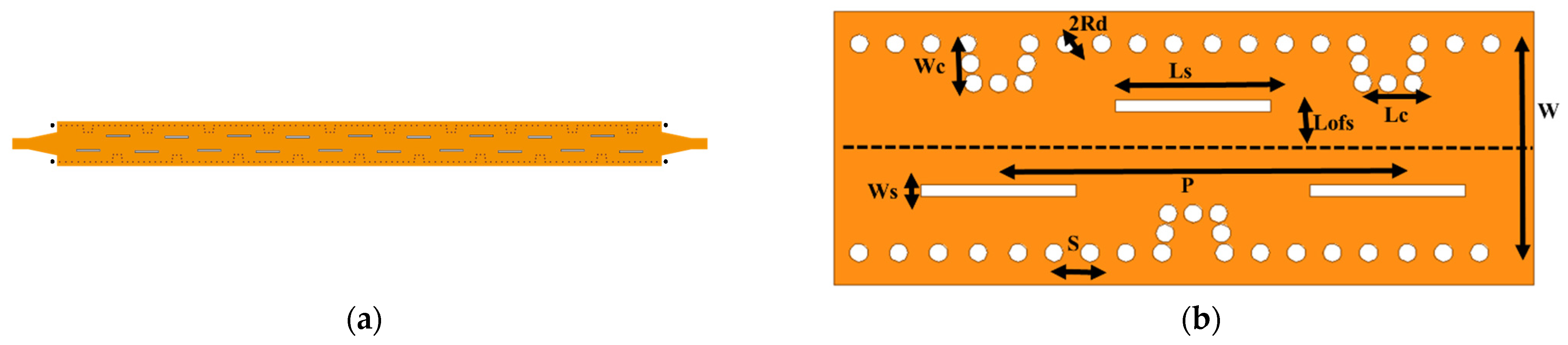
2.3. Full Structure Array Antenna

As this antenna operates at frequencies ranging from 14.5 GHz to 22.5 GHz, it is critical that the feeding structure has good impedance matching in this band. To provide good impedance matching, a wideband microstrip-to-SIW transition scheme is used in the feeding section, as shown in Figure 9. This transition was presented in [39]. When compared with the traditional microstrip-to-SIW transition, using a short metallic via can improve impedance matching. Figure 17 shows the microstrip-to-SIW transition, which compares the traditional design with the proposed one. The return loss for the two types of transitions is shown in Figure 18. One can easily see that the proposed microstrip-to-SIW transition significantly improves the impedance matching over the entire frequency range of 14.5 GHz to 22.5 GHz.

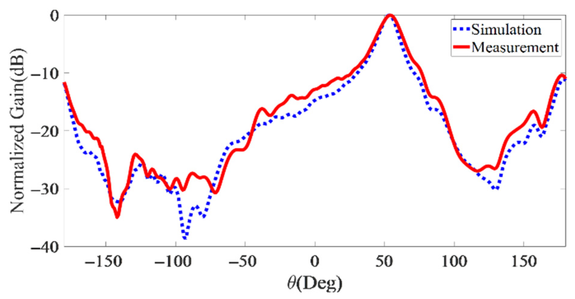
3. Experimental Verifications

In this section, experimental verification of the proposed LWA array is described by comparing the simulation results with those obtained by measurement. For this purpose, a prototype of the LWA array with 19 elements was fabricated based on the dimensions given in Table 1. The fabricated antenna is depicted in Figure 19 and Figure 20 showing the S-parameters of the proposed antenna. The results showed that the proposed design effectively suppressed OSB at broadside frequency. In addition, one can easily see an adequate level of agreement between simulation and measurement.
The normalized radiation pattern of the proposed LWA array, obtained by simulation and measurement, is shown in Figure 21, Figure 22, Figure 23, Figure 24, Figure 25, Figure 26 and Figure 27 for different frequencies. Results confirmed the capability of the proposed antenna to provide continuous beam scanning from backward to forward through the broadside. The measurement and simulation results agreed very well with each other.
The result shows the main beam direction of the proposed antenna continuously varied from −60° to +57.5°, with a maximum gain of 16 dBi. The simulated and measured maximum gain values of the antenna are shown in Figure 28. For a maximum gain of 16 dBi, the measurement results agreed well with the simulated result.
The performance of the proposed antenna was compared with different types of reported SIW LWAs, which are listed in Table 2. For approximately the same length, the maximum gain of the proposed antenna is greater than that of the other reported SIW LWA. Furthermore, the proposed antenna can provide beam-scanning capability in a narrower frequency bandwidth, which is appropriate for applications requiring fast frequency beam scanning.

4. Conclusions

In this paper, a novel SIW LWA was presented for use in continuous beam-scanning applications. The unit cell of the LWA consists of a longitude slot and rectangular-shaped H-plane discontinuity and was proposed to suppress open stopband (OSB). The open stopband suppression was performed using an impedance matching technique. A prototype of the proposed antenna was fabricated, with overall physical dimensions of 7.9 mm × 128 mm, for experimental verification. A comparison of the results demonstrated that an adequate and satisfactory level of agreement between measurement and simulation was achieved. The results confirmed that the proposed SIW LWA can provide continuously scanning in the frequency range of 14.5 to 22.5 GHz between −60 and +57.5 degrees through broadside, with a maximum gain of 16 dBi and radiation efficiency of 71%.

Author Contributions

Conceptualization, S.K. and M.S.; software, S.K.; investigation, S.K.; writing—original draft preparation, S.K.; writing—review and editing, S.K.; supervision, M.S. All authors have read and agreed to the published version of the manuscript.

Funding

This research received no external funding.

Institutional Review Board Statement

Not applicable.

Informed Consent Statement

Not applicable.

Data Availability Statement

Not applicable.

Conflicts of Interest

The authors declare no conflict of interest.

References

  1. Ströber, T.; Tubau, S.; Girard, E.; Legay, H.; Goussetis, G.; Ettorre, M. Shaped Parallel-Plate Lens for Mechanical Wide-Angle Beam Steering. IEEE Trans. Antennas Propag. 2021, 69, 8158–8169. [Google Scholar] [CrossRef]
  2. Johnson, A.D.; Zhong, J.; Venkatakrishnan, S.B.; Alwan, E.A.; Volakis, J.L. Phased Array with Low-Angle Scanning and 46:1 Bandwidth. IEEE Trans. Antennas Propag. 2020, 68, 7833–7841. [Google Scholar] [CrossRef]
  3. Shirkolaei, M.M.; Ghalibafan, J. Scannable Leaky-Wave Antenna Based on Ferrite-Blade Waveguide Operated below the Cutoff Frequency. IEEE Trans. Magn. 2021, 57, 2800510. [Google Scholar]
  4. Shirkolaei, M.M.; Kashani, F.H.; Ghalibafan, J. Backfire-to-endfire scanning capability of a balanced metamaterial structure based on slotted ferrite-filled waveguide. Waves Random Complex Media 2019, 31, 1211–1225. [Google Scholar]
  5. Ettorre, M.; Sauleau, R.; le Coq, L.; Bodereau, F. Single-folded leakywave antennas for automotive radars at 77GHz. IEEE Antennas Wirel. Propag. Lett. 2010, 9, 859–862. [Google Scholar] [CrossRef]
  6. Yang, S.T.; Ling, H. Application of a microstrip leaky wave antenna for range–azimuth tracking of humans. IEEE Geosci. Remote Sens. Lett. 2013, 10, 1384–1388. [Google Scholar] [CrossRef]
  7. Abielmona, S.; Nguyen, H.V.; Caloz, C. Analog direction of arrival estimation using an electronically-scanned CRLH leaky-wave antenna. IEEE Trans. Antennas Propag. 2011, 59, 1408–1412. [Google Scholar] [CrossRef]
  8. Gupta, S.; Abielmona, S.; Caloz, C. Microwave analog real-time spectrum analyzer (RTSA) based on the spectral-spatial decomposition property of leaky-wave structures. IEEE Trans. Microw. Theory Tech. 2009, 57, 2989–2999. [Google Scholar] [CrossRef]
  9. Heddebaut, M. Leaky waveguide for train-to-wayside communicationbased train control. IEEE Trans. Veh. Technol. 2009, 58, 1068–1076. [Google Scholar] [CrossRef] [Green Version]
  10. Oliner, A.A. Leakage from higher modes on microstrip line with application to antennas. Radio Sci. 1987, 22, 907–912. [Google Scholar] [CrossRef]
  11. Shaw, R.; Mandal, M.K. Dual-beam periodic leaky wave antenna with broadside radiation. In Proceedings of the Asia-Pacific Microwave Conference, New Delhi, India, 5–9 December 2016; pp. 1–4. [Google Scholar]
  12. Menzel, W. A new travelling-wave antenna in microstrip. Arch. Elek Ubertragung. 1979, 33, 137–140. [Google Scholar]
  13. Mondal, P.; Wu, K. A leaky-wave antenna in substrate integrated nonradiative dielectric (SINRD) waveguide with controllable scanning rate. IEEE Trans. Antennas Propag. 2013, 61, 2294–2297. [Google Scholar] [CrossRef]
  14. Shaw, R.; Khan, A.A.; Mandal, M.K. Dual-beam substrate integrated waveguide periodic leaky-wave antenna. In Proceedings of the International Conference on Microwave and Photonics, Dhanbad, India, 11–13 December 2015; pp. 1–2. [Google Scholar]
  15. Goldstone, L.O.; Oliner, A.A. Leaky-wave antennas—Part I: Rectangular waveguides. IRE Trans. Antennas Propag. 1959, AP-7, 307–319. [Google Scholar] [CrossRef]
  16. Xu, J.; Hong, W.; Tang, H.; Kuai, Z.; Wu, K. Half-mode substrate integrated waveguide (HMSIW) leaky-wave antenna for millimeter-wave applications. IEEE Antennas Wireless Propag. Lett. 2008, 7, 85–88. [Google Scholar]
  17. Cheng, Y.J.; Hong, W.; Wu, K.; Fan, Y. Millimeter-wave substrate integrated waveguide long slot leaky-wave antennas and twodimensional multibeam applications. IEEE Trans. Antennas Propag. 2011, 59, 40–47. [Google Scholar] [CrossRef]
  18. Alibakhshikenari, M.; Andujar, A.; Anguera, J. New Compact Printed Leaky-Wave Antenna with Beam Steering. Microw. Opt. Technol. Lett. 2016, 58, 215–217. [Google Scholar] [CrossRef]
  19. Deslandes, D.; Wu, K. Substrate integrated waveguide leaky-wave antenna: Concept and design considerations. In Proceedings of the Asia-Pacific Microwave Conference, Suzhou, China, 4–7 December 2005; pp. 346–349. [Google Scholar]
  20. Liu, J.; Jackson, D.R.; Long, Y. Substrate integrated waveguide (SIW) leaky-wave antenna with transverse slots. IEEE Trans. Antennas Propag. 2012, 60, 20–29. [Google Scholar] [CrossRef]
  21. Liu, J.; Tang, X.; Li, Y.; Long, Y. Substrate integrated waveguide leaky-wave antenna with H-shaped slots. IEEE Trans. Antennas Propag. 2012, 60, 3962–3967. [Google Scholar] [CrossRef]
  22. Caloz, C.; Itoh, T. Electromagnetic Metamaterials Transmission Line Theory and Microwave Applications; Wiley: New York, NY, USA, 2005. [Google Scholar]
  23. Zhang, Q.; Wu, G.C.; Wang, G.M.; Liang, J.G.; Gao, X.J. Beam scanning antenna with wideband broadside radiation based on multilayered substrate integrated waveguide composite right/left-handed structure. Frequenz 2017, 71, 29–35. [Google Scholar] [CrossRef]
  24. Xu, F.; Wu, K.; Zhang, X. Periodic leaky-wave antenna for millimeter wave applications based on substrate integrated waveguide. IEEE Trans. Antennas Propag. 2010, 58, 340–347. [Google Scholar]
  25. Cheng, Y.; Hong, W.; Wu, K. Millimeter-wave half mode substrate integrated waveguide frequency scanning antenna with Quadri-polarization. IEEE Trans. Antennas Propag. 2010, 58, 1848–1855. [Google Scholar] [CrossRef]
  26. Williams, J.T.; Baccarelli, P.; Paulotto, S.; Jackson, D.R. 1-D Combline Leaky-Wave Antenna with the Open-Stopband Suppressed: Design Considerations and Comparisons with Measurements. IEEE Trans. Antennas Propag. 2013, 61, 4484–4492. [Google Scholar] [CrossRef]
  27. Otto, S.; Al-Bassam, A.; Rennings, A.; Solbach, K.; Caloz, C. Transversal Asymmetry in Periodic Leaky-Wave Antennas for Bloch Impedance and Radiation Efficiency Equalization through Broadside. IEEE Trans. Antennas Propag. 2014, 62, 5037–5054. [Google Scholar] [CrossRef]
  28. Alibakhshikenari, M.; Virdee, B.S.; Shukla, P.; Wang, Y.; Azpilicueta, L.; Naser-Moghadasi, M.; See, C.H.; Elfergani, I.; Zebiri, C.; Abd-Alhameed, R.A.; et al. Impedance Bandwidth Improvement of a Planar Antenna Based on Metamaterial-Inspired T-Matching Network. IEEE Access 2021, 9, 67916–67927. [Google Scholar] [CrossRef]
  29. Alibakhshikenari, M.; Virdee, B.S.; Shukla, P.; See, C.H.; Abd-Alhameed, R.A.; Falcone, F.; Limiti, E. Improved Adaptive Impedance Matching for RF Front-End Systems of Wireless Transceivers. Sci. Rep. 2020, 10, 14065. [Google Scholar] [CrossRef] [PubMed]
  30. Alibakhshikenari, M.; Virdee, B.S.; See, C.H.; Abd-Alhameed, R.A.; Falcone, F.; Limiti, E. Impedance matching network based on metasurfaces (2-D metamaterials) for electrically small antennas. In Proceedings of the IEEE International Symposium on Antennas and Propagation and North American Radio Science Meeting, Montreal, QC, Canada, 5–10 July 2020; pp. 1953–1954. [Google Scholar]
  31. Rahmani, M.H.; Deslandes, D. Backward to Forward Scanning Periodic Leaky-Wave Antenna with Wide Scanning Range. IEEE Trans. Antennas Propag. 2017, 65, 3326–3335. [Google Scholar] [CrossRef]
  32. Mallahzadeh, A.; Mohammad-Ali-Nezhad, S. Periodic Collinear-Slotted Leaky Wave Antenna with Open Stopband Elimination. IEEE Trans. Antennas Propag. 2015, 63, 5512–5521. [Google Scholar] [CrossRef] [Green Version]
  33. Ranjan, R.; Jayanta, G. SIW-based leaky-wave antenna supporting wide range of beam scanning through broadside. IEEE Antennas Wirel. Propag. Lett. 2019, 18, 606–610. [Google Scholar] [CrossRef]
  34. Marcuvitz, N. Waveguide Handbook; Peter Peregrinus: London, UK, 1986. [Google Scholar]
  35. Weisshaar, A.; Mongiardo, M.; Tripathi, V.K. CAD-oriented equivalent circuit modeling of step discontinuities in rectangular waveguides. IEEE Microw. Guided Wave Lett. 1996, 6, 171–173. [Google Scholar] [CrossRef]
  36. Marcuvitz, N. Waveguide Handbook; McGraw-Hill: New York, NY, USA, 1951. [Google Scholar]
  37. Chen, X.; Wu, K. Substrate Integrated Waveguide Filter: Basic Design Rules and Fundamental Structure Features. IEEE Microw. Mag. 2014, 15, 108–116. [Google Scholar] [CrossRef]
  38. Lyu, Y.L.; Liu, X.-X.; Wang, P.-Y.; Erni, D.; Wu, Q.; Wang, C.; Kim, N.-Y.; Meng, F.-Y. Leaky-wave antennas based on noncutoff substrate integrated waveguide supporting beam scanning from backward to forward. IEEE Trans. Antennas Pxropag. 2016, 64, 2155–2164. [Google Scholar] [CrossRef]
  39. Kordiboroujeni, Z.; Bornemann, J. New wideband transition from microstrip line to substrate integrated waveguide. IEEE Trans. Microw. Theory Tech. 2014, 62, 2983–2989. [Google Scholar] [CrossRef]
  40. Zhou, W.; Liu, J.; Long, Y. Investigation of Shorting Vias for Suppressing the Open Stopband in an SIW Periodic Leaky-Wave Structure. IEEE Trans. Microw. Theory Tech. 2018, 66, 2936–2945. [Google Scholar] [CrossRef]
Figure 1. Proposed SIW LWA: (a) array configuration; (b) unit cell.
Electronics 11 01804 g001
Figure 2. Ideal waveguide with longitude slot.
Electronics 11 01804 g002
Figure 3. T-Network model for longitude slot.
Electronics 11 01804 g003
Figure 4. Normalized series and shunt impedance of T-network for longitude slot.
Electronics 11 01804 g004
Figure 5. Decomposition of rectangular-shaped H-plane discontinuity.
Electronics 11 01804 g005
Figure 6. Equivalent circuit: (a) H-plane step; (b) short waveguide section; (c) rectangular-shaped H-plane discontinuity.
Electronics 11 01804 g006
Figure 7. Π-network equivalent circuit for waveguide with rectangular shaped H-plane discontinuity.
Electronics 11 01804 g007
Figure 8. Real and imaginary parts of the series and shunt impedance in π-network equivalent circuit.
Electronics 11 01804 g008
Figure 9. Approximated model consists of shunt admittance for rectangular-shaped H-plane discontinuity.
Electronics 11 01804 g009
Figure 10. Variation in shunt reactance regarding width and length of discontinuity.
Electronics 11 01804 g010
Figure 11. T-network circuit equivalent for proposed unit cell consisting of longitude slot and rectangular-shaped H-plane discontinuity.
Electronics 11 01804 g011
Figure 12. Imaginary part of shunt admittance for longitude slot, rectangular-shaped H-plane discontinuity, and proposed unit cell.
Electronics 11 01804 g012
Figure 13. Schematic of SIW modeling of (a) longitude slot, (b) rectangular-shaped h-plane discontinuity, and (c) proposed unit cell.
Electronics 11 01804 g013
Figure 14. Imaginary part of the shunt admittance in the circuit equivalent for longitude slot, rectangular-shaped h-plane discontinuity, and proposed unit cell.
Electronics 11 01804 g014
Figure 15. Dispersion diagram of unit cell with longitudinal slot.
Electronics 11 01804 g015
Figure 16. Dispersion diagram of unit cell with longitudinal slot and H-plane Step.
Electronics 11 01804 g016
Figure 17. Microstrip to SIW transition: (a) traditional design; (b) proposed design.
Electronics 11 01804 g017
Figure 18. Return loss of different types of microstrip-to-SIW transition.
Electronics 11 01804 g018
Figure 19. Prototype of fabricated SIW LWA.
Electronics 11 01804 g019
Figure 20. Simulated and measured S-parameters for LWA array.
Electronics 11 01804 g020
Figure 21. Simulated and measured radiation patterns at 14.5 GHz.
Electronics 11 01804 g021
Figure 22. Simulated and measured radiation patterns at 16 GHz.
Electronics 11 01804 g022
Figure 23. Simulated and measured radiation patterns at 17 GHz.
Electronics 11 01804 g023
Figure 24. Simulated and measured radiation patterns at 18 GHz.
Electronics 11 01804 g024
Figure 25. Simulated and measured radiation patterns at 19 GHz.
Electronics 11 01804 g025
Figure 26. Simulated and measured radiation patterns at 21 GHz.
Electronics 11 01804 g026
Figure 27. Simulated and measured radiation patterns at 22.5 GHz.
Electronics 11 01804 g027
Figure 28. Measured and simulated maximum gain values of antenna.
Electronics 11 01804 g028
Table 1. Parameters of SIW Periodic LWA.
ParameterValue (mm)ParameterValue (mm)
W6.9Lc1.15
Lofs2Wc1.15
Rd0.3Ls5.2
S1.2Ws0.4
p12.8
Table 2. Comparison of performance of SIW-based LWAS.
RefSlot TypeεrTotal Length
0)
Band
Width (%)
Operating Band
Width (GHz)
Scanning
Range (deg)
Max Gain (dBi)Efficiency (%)
[30]Longitudinal6.157.63720–29−50 to 4512.2-
[32]Longitudinal3.55-408–12−35 to 3512.591
[33]Longitudinal3.6665510–17.5−49 to 6914.268
[38]Transverse and
Longitudinal
3.666439–14−40 to 3512-
[40]Transverse10.211.21613.2–15.6−61 to 4214.1-
ProposedLongitudinal3.556.74314.5–22.5−60 to 57.51682
Publisher’s Note: MDPI stays neutral with regard to jurisdictional claims in published maps and institutional affiliations.

