Article

Torque Ripple Suppression Method of Switched Reluctance Motor Based on an Improved Torque Distribution Function

1
School of mechatronic Engineering and Automation, Shanghai University, Shanghai 200072, China
2
School of Mechanical Engineering, Shanghai Jiao Tong University, Shanghai 200240, China
*
Author to whom correspondence should be addressed.
Electronics 2022, 11(10), 1552; https://doi.org/10.3390/electronics11101552
Submission received: 26 April 2022 / Revised: 9 May 2022 / Accepted: 10 May 2022 / Published: 12 May 2022
(This article belongs to the Special Issue Intelligent Systems and Control Application in Autonomous Vehicle)

Abstract

:
Currently, torque ripple is a crucial factor hindering the application of the switched reluctance motor (SRM). Hence, it is of crucial importance to suppress this undesirable torque ripple. This paper proposes a new torque ripple suppression method of SRM based on the improved torque distribution function. Firstly, the electromagnetic characteristic model of a 8/6-pole four-phase SRM is established, and the cerebellar model articulation controller (CMAC) is used to complete the learning of each model. Then, the improved torque distribution function is planned based on the torque model to give the reference torque of each phase, and the inverse torque model is used to realize the mapping of the reference torque to the reference flux linkage. Finally, the duty of each phase voltage PWM wave modulation is output based on the PID control theory. The proposed accurate model-based planning scheme is implemented on the simulation platform, and the results shows that the maximum torque fluctuation of the output results is reduced to within 3%, and the average error is reduced to within 1%, which is much lower than the error of 15% under the traditional direct torque control method.

Graphical Abstract

1. Introduction

Due to its simple structure, low cost, and high reliability, the switched reluctance motor (SRM) has been highlighted for many industrial applications [1,2]. For instance, with ever-increasing concerns over environmental and cost issues associated with permanent magnet machines, there is a technical trend to utilize SRMs in some mass production markets. The SRM is gaining much interest for electric vehicles, aerospace applications, mining drive, screw rotary compressor drive, doors actuation system, air-conditioning drives in the train, and other applications, due to its rare earth-free characteristic and excellent performance [3,4,5,6,7]. Recently, research on various aspects of SRMs has also become a hot spot. New material and structures are adopted in the SRM drive system for high-speed application. Ahmad et al. [8] developed a SiC MOSFET based high-switching frequency power converter for driving high-speed SRM. New structures of SRM have been developed as well, such as asymmetric rotor pole type bearingless SRM [9], double-rotor permanent magnet switched reluctance motor (DR-PMSRM) [10], and dual-stator bearingless switched reluctance motor (DSBSRM) [11]. Besides, modern research about SRM explored has explored new applications. An integrated drive for three-phase SRM that combines a battery-powered bidirectional dc/dc converter to provide bidirectional power transfer in practice is proposed in [12].
However, the torque of SRM is related to the change rate of inductance and current, and the change rate of inductance in the minimum and maximum inductance regions is very small, which will lead to the decrease of torque in the commutation section of the motor and result in torque ripple [13,14]. The SRM suffers from inherent torque ripple, which limits its application in the industrial potential market. In order to suppress the torque ripple of SRM, researchers have put forward an optimization scheme considering two aspects of SRM structure design and control strategy. In terms of motor structure optimization design, Kondelaji et al. [15] applied the modular stator and segmented rotor to SRM. Piyush et al. [16] and Bilgin et al. [17] increased the number of rotor poles, and Sheth et al. [18] optimized the pole arc length of the stator and rotor of the motor. Choi et al. [19] added pole shoes on both sides of the rotor pole top. Lee et al. [20] changed the surface shape of the salient pole. Woo et al. [21] reduced the torque ripple by slotting the side of the rotor salient pole. The structural optimization method is suitable for the early design stage. However, for the SRM that has been put into use, it can only be realized through optimization of the control strategy. Under the traditional angle control strategy and current chopping control strategy, reducing the torque ripple can be realized by optimizing the switching angle [22,23] and current waveform modulation [24,25,26]. Such methods are easy to implement, but the torque ripple reduction cannot be achieved in a wide speed range. Average torque control [27] and direct torque control strategy [28] are also commonly used methods to suppress torque ripple, which use torque or flux linkage error as the controller input and output voltage control signal to achieve the purpose of torque control. The two types of methods have the disadvantage that the torque ripple suppression effect is weak in the commutation interval. The torque ripple suppression method based on the transfer distribution function [29,30] can effectively reduce the torque ripple in the commutation interval. It first defines the torque share function (TSF), and then tracks the planned torque curve. Most of the previous research focused on optimizing the control parameters of existing TSFs according to one or two secondary objectives. In [31], several popular TSFs, including linear, cubic, sinusoidal, and exponential TSFs, are investigated and evaluated. These methods did not consider the nonlinear characteristics of SRM torque, and the actual output greatly deviates from the planning value due to the rapid change of the inductance at the beginning and end of the overlapping region, which weakened the vibration suppression effect.
How to obtain the TSF that can reduce torque ripple and realize the conversion from reference torque to reference flux is the key to the torque ripple suppression strategy based on the torque distribution function. Lin et al. [32] proposed a current controller with adjustable PI gain and back EMF decoupling function to estimate back EMF and incremental inductance online, which improved the tracking accuracy of reference current waveform and effectively reduced torque fluctuation. Gobbi et al. [33] proposed a new current hysteresis controller, which could achieve higher tracking accuracy and reduce torque fluctuation by tracking the optimized reference current. Sahoo et al. [34,35] proposed a current controller based on iterative learning control. The current control method of iterative learning control needs a certain iteration cycle to converge, and the tracking effect of time-varying reference current is poor. Considering that the intelligent control has strong self-learning ability and adaptive ability, it can be used for on-line current optimization to reduce the torque ripple of SRM. Mir et al. [36] used an adaptive fuzzy controller to control torque and neuro fuzzy compensation scheme to optimize the phase current to suppress torque ripple. Reay et al. [37] learned the electromagnetic characteristic model of SRM based on a cerebellar model joint controller and achieved the effect of torque ripple suppression in a wide speed range. Therefore, reasonable planning of the reference torque and the accurate realization of the reference current waveform of each phase represent an important factor affecting the effect of torque ripple suppression.
How to obtain the torque distribution function that can reduce the torque ripple and realize the conversion from the reference torque to the reference flux linkage is the key to the torque ripple suppression strategy based on the torque distribution function. Based on this, this chapter firstly constructs the torque distribution function based on the accurate electromagnetic characteristic experimental model, and then uses the cerebellar neural network (CMAC) to realize the conversion from reference torque to reference flux linkage, and finally realize accurate torque tracking. Compared with the traditional direct torque control strategy, the results show that the proposed torque ripple suppression method can effectively reduce the torque ripple. In Section 2, the improved torque distribution function is presented. Section 3 shows the torque ripple suppression method based on the improved torque distribution function. In Section 4, the simulation verification and analysis are implemented to validate the proposed method. Finally, the conclusion is drawn in Section 5.

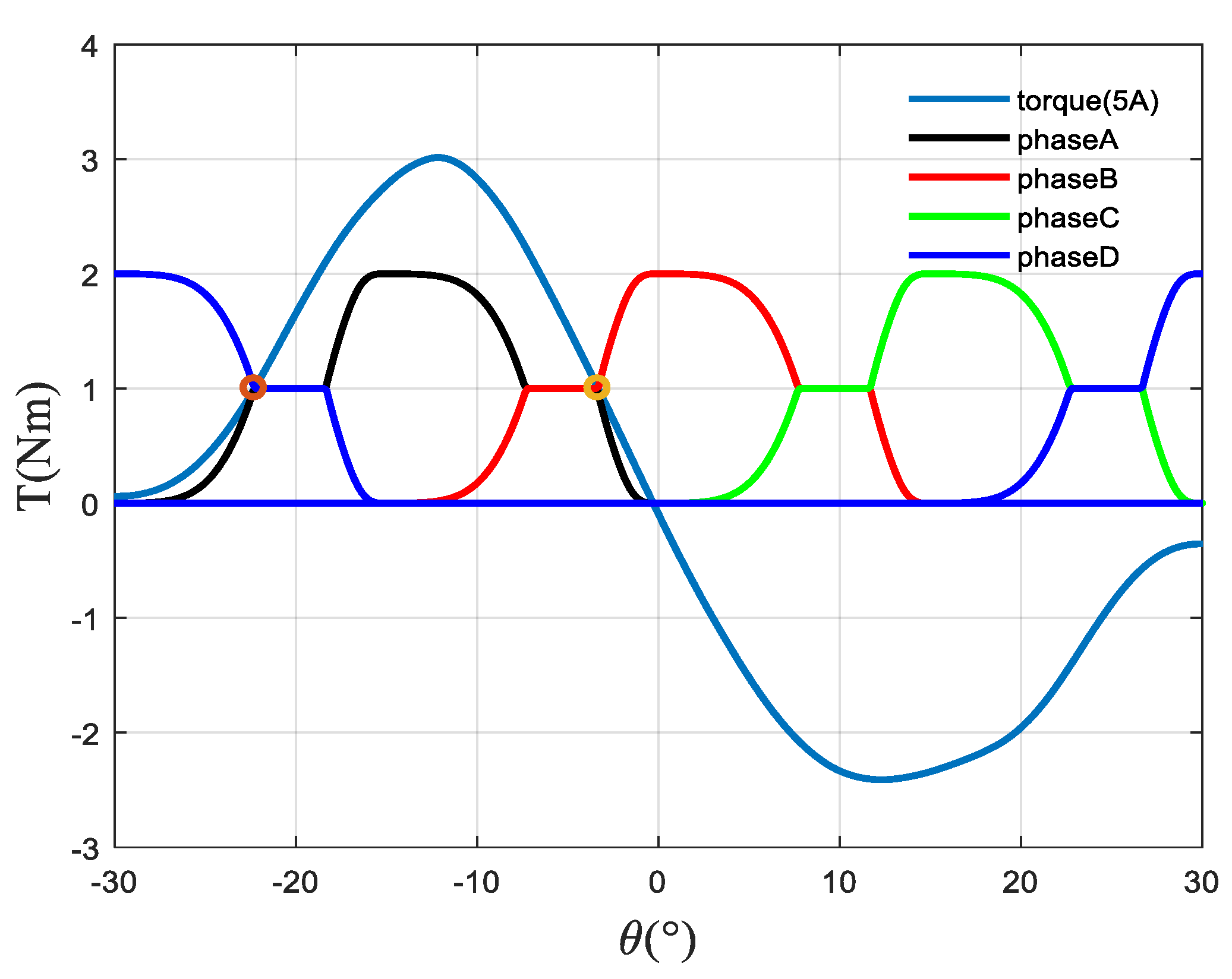
2. An Improved Torque Distribution Function

The double salient pole structure and pulse power supply mode of SRM make the electromagnetic characteristics of the motor show serious nonlinear characteristics. The torque output of SRM is superimposed by the pulse torque of each phase, and the output is not constant, which leads to the generation of torque ripple. How to minimize torque ripple is one of the important components of SRM performance optimization.
The torque control method based on TSF has received extensive attention due to its wide speed regulation range and high control precision. The reference torque for each phase of the method can be represented by a TSF, where the sum of the reference torques is equal to the total desired output torque. However, the traditional TSF-based torque control strategy does not take into account the nonlinear characteristics of SRM, which makes the actual torque in the commutation interval deviate from the reference torque. Therefore, this paper proposes a TSF planning method based on an accurate electromagnetic characteristic model, which fully considers the nonlinear characteristics of the SRM and considers the limits of the maximum current, torque, and voltage. The actual output torque of each phase can easily track the reference torque, and the total output torque can accurately track the expected torque to reduce the torque ripple.
The tracking of the reference torque for any phase can be achieved by direct torque control. The reference feedback signal can be obtained according to the reference torque, which is generally the reference current or the reference flux linkage. Then, by comparing the actual feedback signal and the reference feedback signal, the difference is used as the input of the controller. Moreover, the output of the controller is the switching signal of the power amplifier, which finally realize single-phase torque control. Figure 1 shows the block diagram of direct torque control with the flux linkage signal as feedback.
The torque T of the SRM is expressed by the following formula:
T = 1 2 i ψ ( i , θ ) θ .
Since the winding current i is always positive, the positive or negative of the SRM torque output is determined by ψ ( i , θ ) / θ . When ψ ( i , θ ) / θ > 0 and T > 0, the SRM is accelerating, and the phase of flux linkage is ahead of the rotor position angle θ. When ψ ( i , θ ) / θ < 0 and T < 0, the SRM is decelerating, and the flux linkage lags behind the rotor position angle θ at this time. According to the previous analysis, it can be known that the torque control of the SRM can be realized by controlling the change of the flux linkage. The voltage and flux linkage across a single-phase winding satisfy the following relationship:
ψ ( i , θ ) = ( U k R i ) d t ,
where Uk is the voltage at both ends of the winding, and R is the internal resistance of the winding. Under the premise of ignoring the internal resistance voltage drop, and discretizing Formula (2), we can get:
ψ k + 1 ( i k + 1 , θ k + 1 ) = ψ k + 1 ( i k , θ k ) + U k Δ t .
As can be seen from Equation (3), flux linkage control can be achieved by adjusting the voltage across the winding. Voltage control generally uses voltage pulse width modulation (PWM). For PWM waves with a fixed period, the voltage across the winding can be controlled by changing the pulse width. The duty cycle D can be used to characterize the pulse width, and the following relationship is satisfied between the rate of change of the flux linkage within a control period and the supply voltage U:
lim Δ t 0 ( ψ * ( i , θ + ω Δ t ) ψ ( i , θ ) Δ t ) = ( 2 D 1 ) U ,
where ψ * ( i , θ + ω t ) is the reference flux linkage obtained according to the reference torque, and ψ ( i , θ ) is the actual flux linkage value, the relationship between the duty cycle D of the phase voltage PWM wave and the power supply voltage U can be obtained by Formula (4), and torque control is realized by controlling the duty cycle Δt of the phase voltage PWM waveform.
D = ψ * ( i , θ + ω Δ t ) ψ ( i , θ ) 2 U Δ t + 0.5 .
The reference flux linkage ψ * ( i , θ + ω t ) is obtained through the torque inverse model. The model reflects the mapping relationship between rotor angle and torque to flux linkage. Existing modeling methods include the look-up table method, analytical method, intelligent modeling method, and so on. The table look-up method and the analytical method generally have shortcomings, such as low precision and complex fitting function. The accuracy of the reference flux linkage has a significant impact on the torque ripple suppression effect, and an accurate reverse torque model is required to realize the online output of the reference flux linkage. Intelligent modeling methods based on fuzzy control, neural network, support vector machine, and other related theories are widely used in the nonlinear modeling of SRMs, and their powerful self-learning ability can approximate any nonlinear mapping. Using the intelligent modeling method to learn the existing electromagnetic characteristic data to realize the identification of the model, the nonlinear characteristic of the SRM can be described ideally. Therefore, a torque inverse model output method based on CMAC is proposed to achieve accurate mapping from reference torque to reference flux linkage.
The torque control strategy proposed in this manuscript is shown in Figure 2. Firstly, an experimental model of the electromagnetic characteristics of the SRM is established based on the pulse voltage ergodic response method, including the flux linkage model, the torque model, and the torque inverse model. Then, based on the torque model, the torque distribution function is planned to give the reference torque of each phase, and the CMAC is used to realize the conversion of the reference torque to the reference flux linkage. Finally, the duty cycle of the voltage PWM wave modulation of each phase is output based on the PID control theory, and the PID controller is adopted to adjust the duty cycle of the PWM so that the actual flux linkage can keep up with the expected reference value. To the power converter, torque control is achieved by adjusting the voltage across the windings of each phase.

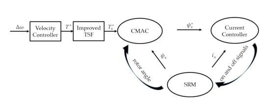
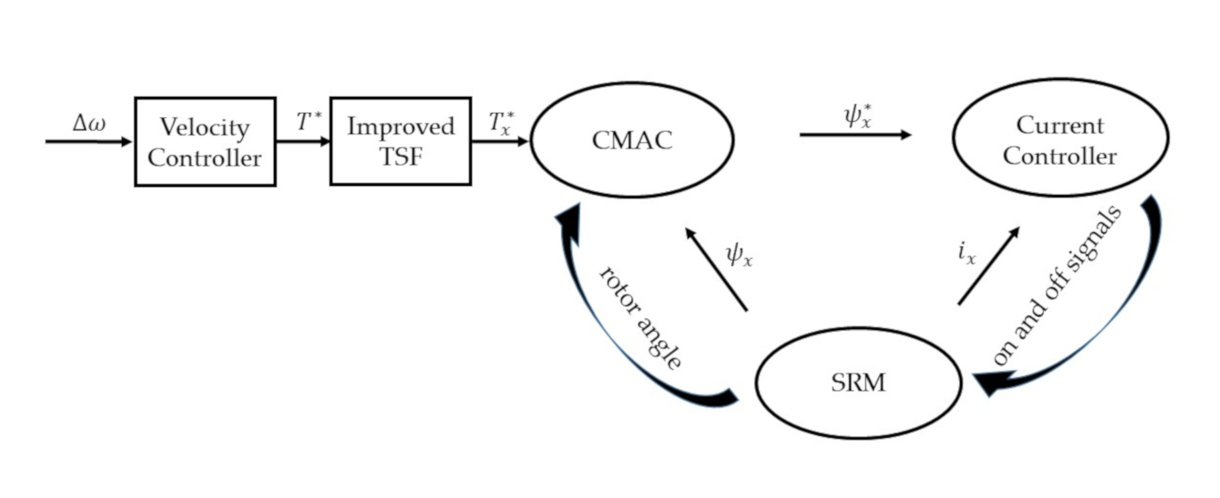
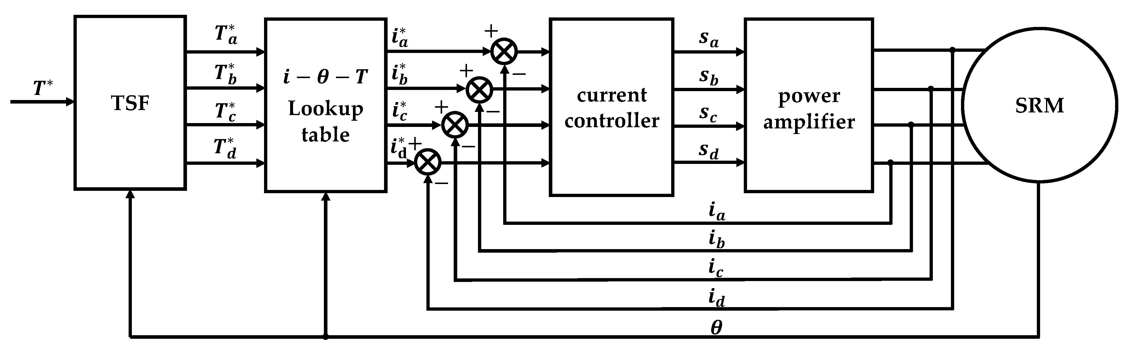
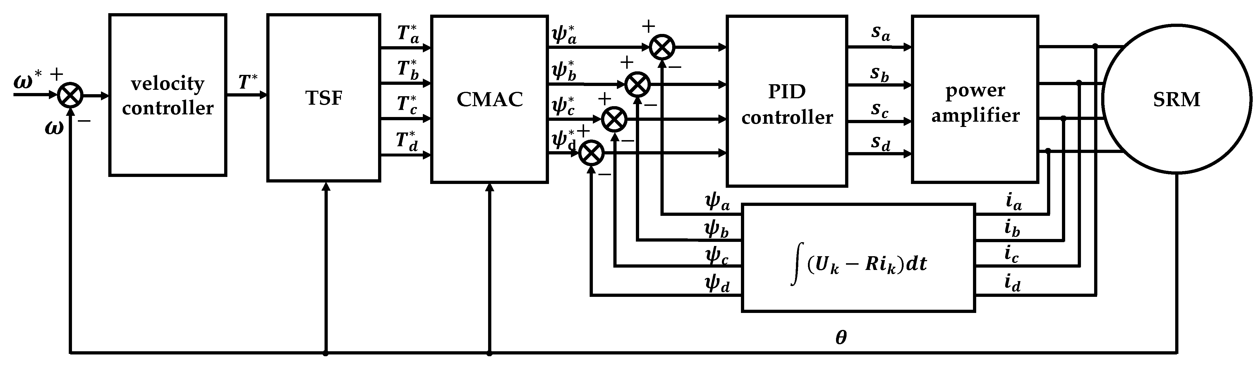
3. Torque Ripple Suppression Method Based on the Improved TSF

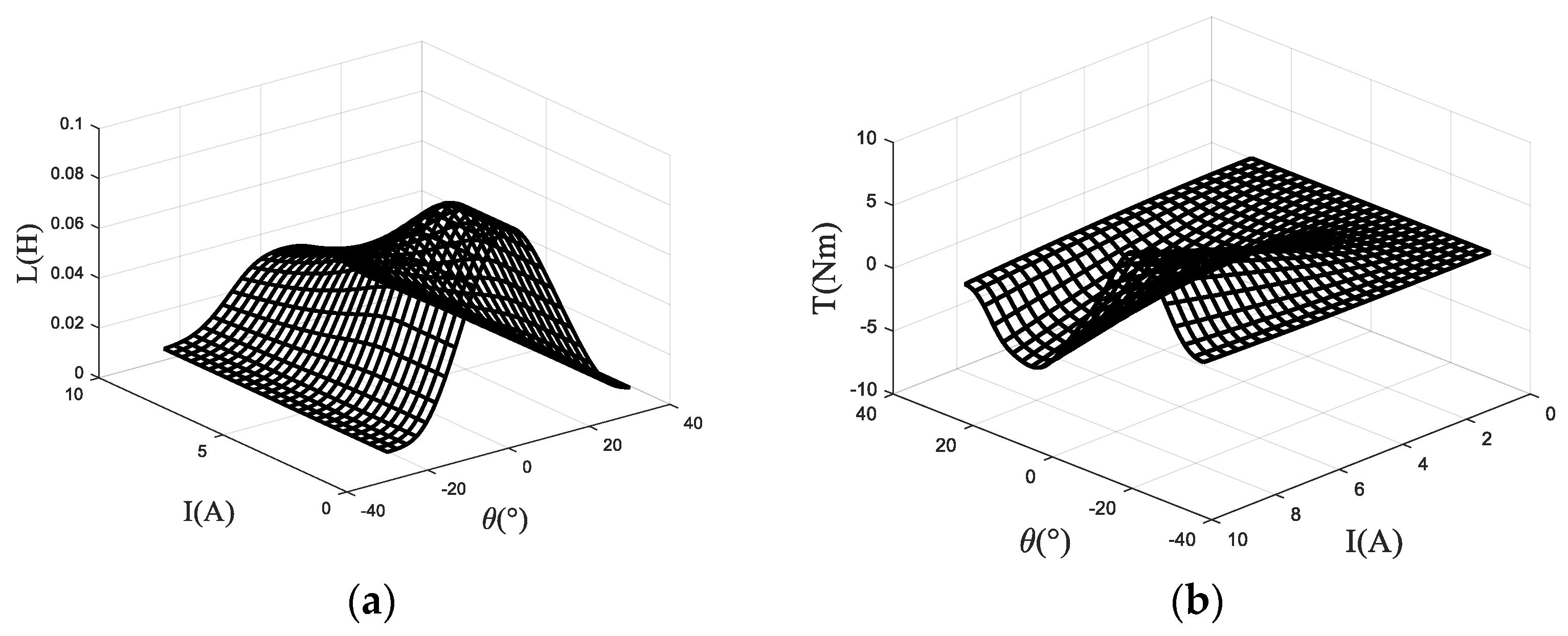
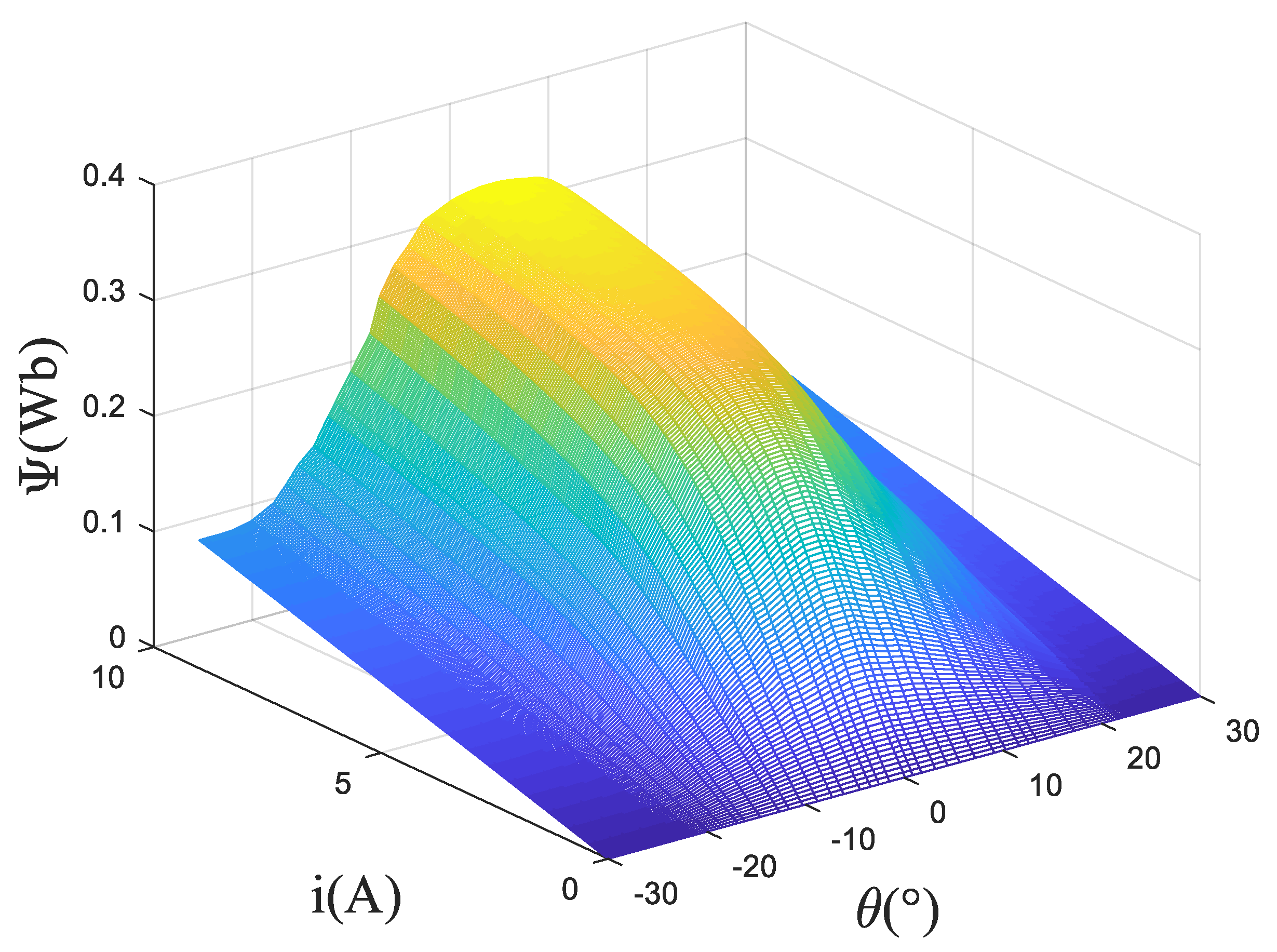
3.1. Acquisition of Flux Linkage Characteristics

The instantaneous voltage across the terminals of a single phase of the SRM winding is related to the flux linked in the winding by the Faraday’ law,
V = R i + d ψ d t ,
where V is the terminal voltage, i is the phase current, R is the motor resistance, and ψ is the flux linked by the winding, which varies as a function of rotor position θ and current i. The partial derivative of the flux linkage ψ with respect to the phase current i is the inductance L, which is also a function of rotor position θ and current i. Thus, equation (6) can be expanded as:
V = R i + L ( i , θ ) d i d t + ψ ( i , θ ) θ ω .
when the rotor position is kept constant at the position angle θ = θ0, the rotational speed ω = 0. Then, the flux linkage at θ0 can be simplified to the formula as follows,
ψ θ 0 = ( V R i ) d t
It can be seen from Formula (8) that the variation curve of flux linkage relative to current at θ = θ0 can be obtained by integrating the voltage at both ends of the winding with time when the rotor of the motor is fixed at θ0. The ψ-i curve in the whole electric cycle under different rotor position angles can be obtained by repeating the calculation steps described above at different positions, which is the electromagnetic characteristic model of flux linkage relative to phase current and position.
The magnetic linkage characteristics are obtained according to pulse voltage ergodic response method. Specifically, the rotor position angle is fixed first, and a certain pulse voltage is applied to the winding. Then, use the acquisition card to record the changing curve of current with time. After rotating the rotor position, repeat measuring and recording the changing curve of current with time until the experiment of one electrical cycle is completed. Perform preprocessing operations such as filtering on the original data, and then calculate the flux linkage according to Formula (8). The three-dimensional surface of the flux linkage relative to the rotor angle and phase current is shown in the Figure 3. Based on this model, the three-dimensional surfaces of inductance relative to the rotor angle and phase current and torque relative to the rotor angle and phase current of the SRM are calculated and shown in Figure 4.

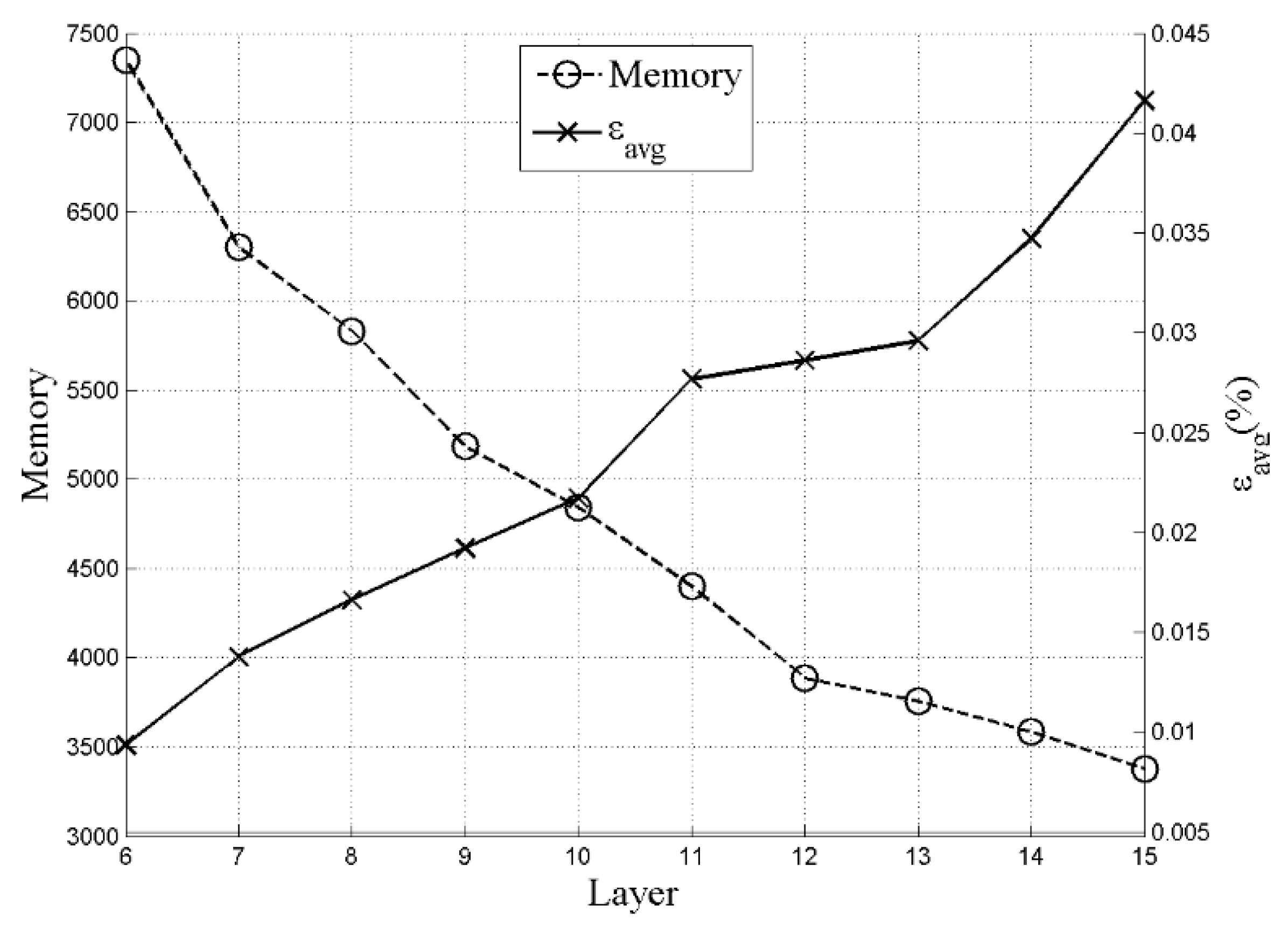
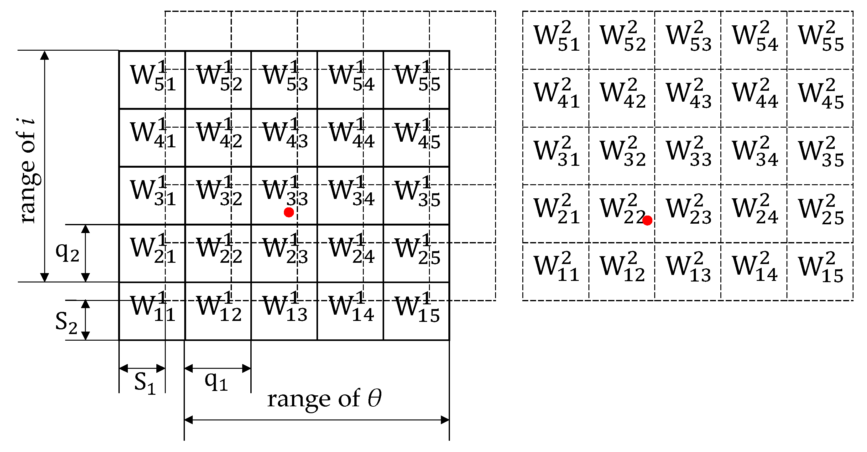
3.2. Model Learning Based on CMAC

The CMAC is a simple and fast neural network based on local approximation, which is established by the input and output data without depending on the mathematical model of the system. The memory structure of CMAC is established by miscellaneous storage and the accuracy can be improved by increasing the number of layers. Figure 5 shows simplified instructions for a two-layer structure. In each layer, the input space is divided into lattices, and the interval in direction θ is q1 while the interval in direction i is q2. By offsetting the first layer with [S1, S2], the second layer of memory is obtained. W i k j k k indicates the weight value stored in the cell of the kth layer with the address of [ik, jk]. In order to obtain the same accuracy as the original model, let Sn = qn/M. Hence, ik and jk can be obtained by the following formula,
{ i k = fix ( θ q 1 k 1 L + 2 ) , j k = fix ( i q 2 k 1 L + 2 ) . ( k = 1 M ) ;
Each set of [θ, i] activates a square in each layer which is marked with the red dot, for example, W 33 1 in the first layer and W 22 2 in the second layer are activated respectively in the Figure 5. Then, add the active weight of each layer according to the formula as follows:
L C M A C = k = 1 l W i k j k k
From the steepest descent rule, the following weight update method is applied:
W i k j k k = W i k j k k + ρ p = 1 P ( L r e a l L C M A C )
where P is the number of relevant training samples and ρ is the learning rate. Figure 6 shows the memory and fitting error versus the number of CMAC layers. After comprehensively considering the error and memory consumption, the number of selected memory layer is 13.

3.3. Implementation of Proposed Algorithm

First, limit the chopping current hysteresis range to 4.9–5.1 A, and then limit the maximum planned current to 5 A. The relationship between the torque and the rotor position angle when the current is 5 A can be obtained from the torque accurate model, and then the torque planning can be carried out on this basis. Figure 7 shows the torque plan waveform of each phase for the 4-phase SRM.
In Figure 7, θ is the rotor position angle of the first phase. For a single phase, it is necessary to find the rotor position angle corresponding to the current imax and the torque 0.5 T * (1 N), as indicated by the circle in the figure. In this way, two angles can be found, and the one close to −30° is recorded as θ1, while the one close to 0° is recorded as θ2, and then the torque is initially planned according to Formula (12):
T r e f ( θ , T * ) = { T ( θ , i max ( θ + 30 ° ) θ 1 + 30 ° ) , ( 30 ° < θ < θ 1 ) ; T * / 2 , ( θ 1 < θ < θ 2 15 ° ) ; T * T ( θ + 15 ° , i max ( θ + 15 ° ) θ 2 ) , ( θ 2 15 ° < θ < 15 ° ) ; T * T ( θ 15 ° , i max ( θ + 15 ° ) θ 1 + 30 ° ) , ( 7.5 ° < θ < θ 1 + 15 ° ) ; T * / 2 , ( θ 1 + 15 ° < θ < θ 2 ) ; T ( θ , i max θ θ 2 ) , ( θ 2 < θ < 0 ° ) .
where T(θ, i) is the accurate torque model, and T* is the expected value of the total torque. Substituting Tref(θ, T*) into the torque accurate model can deduce the planned value iref(θ, T*) of the control current, and then obtain the planned flux linkage value ψref(θ, T*) according to the torque inverse model. This planning method can theoretically obtain a constant torque. However, the current cannot be reduced to 0 A before the rotor position angle 0° as planned due to the large flux linkage in the last segment, when the rotation speed is large. Moreover, if the current is not 0 between the rotor position angle of 0° and 30°, the braking torque will be generated, and the torque fluctuation will be increased. Therefore, the influence of rotating speed on the actual current change rate needs to be considered for the planning model. The turn-off angle θoff is introduced here to ensure that the current is reduced to 0 A before 0°. The time required for the current to decrease to 0 A at the rotational speed ω after the IGBT is turned off can be expressed as follows:
t = ψ o f f ( θ o f f , T * ) V S = 0 ° θ o f f ω
where ψoff is the flux linkage at the moment of turn-off, and VS is the power supply voltage. From this formula, θoff(T*) and ψoff(T*) can be calculated. The third segment function in the revised torque plan is presented as:
T r e f ( θ , T * ) = T * T ( θ + 15 ° , i ( ψ 1 ( θ + 15 ° , T * ) , θ + 15 ° ) ) ( θ o f f 15 ° < θ < 15 ° )
where i(ψ, θ) is the inverse output model of the accurate flux linkage model, and ψ1(θ) is the change relationship of the flux linkage with the turn-off angle after the IGBT is turned off. If ignoring the resistance drop, the formula can be simplified as:
ψ 1 ( θ , T * ) = ψ o f f ( T * ) V S θ ω ( θ o f f < θ < 0 ° )
After the above correction, taking the rotation speed of 1000 rpm as an example, the control current and the control flux linkage can be obtained as shown in Figure 8.

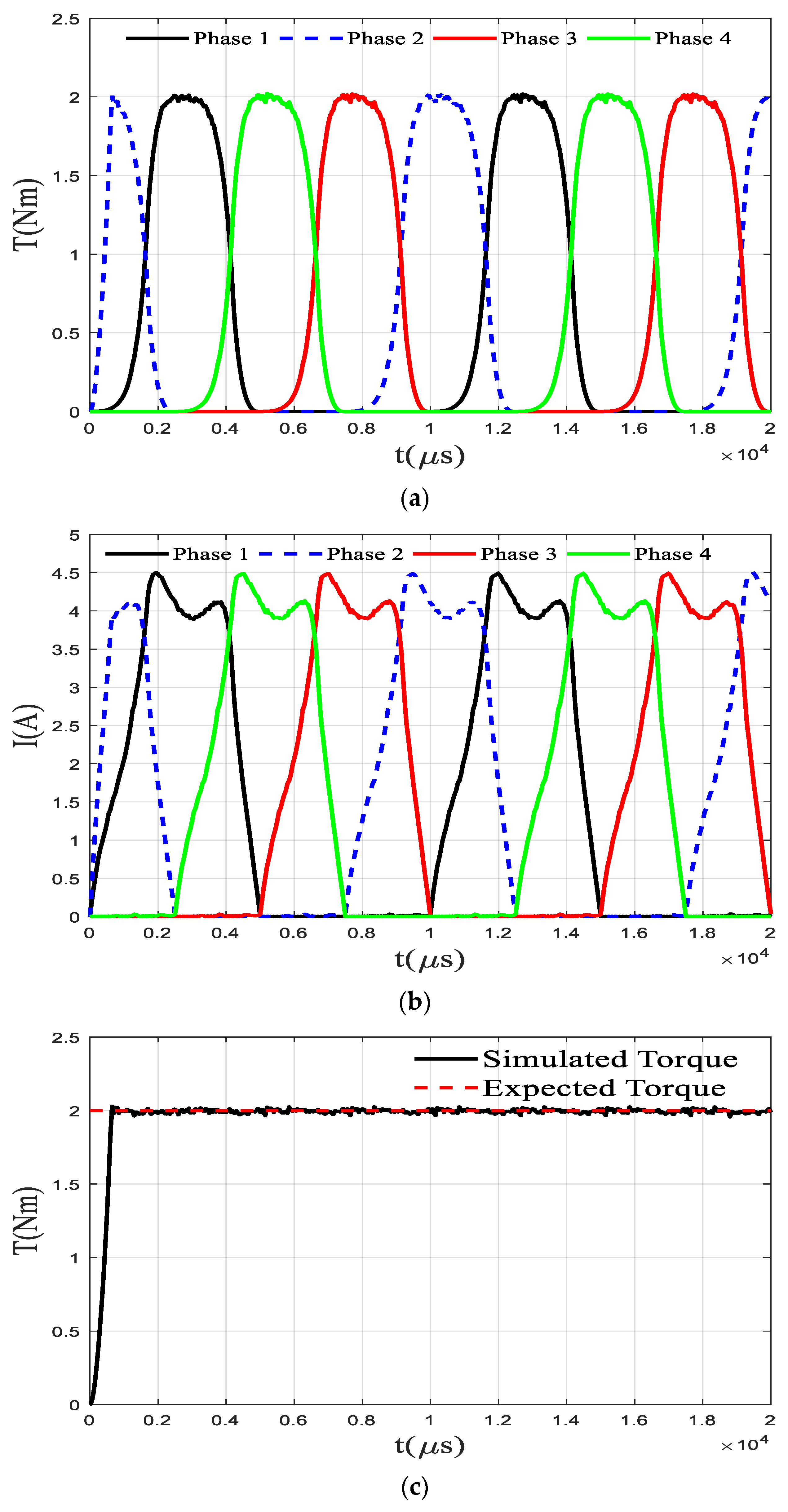
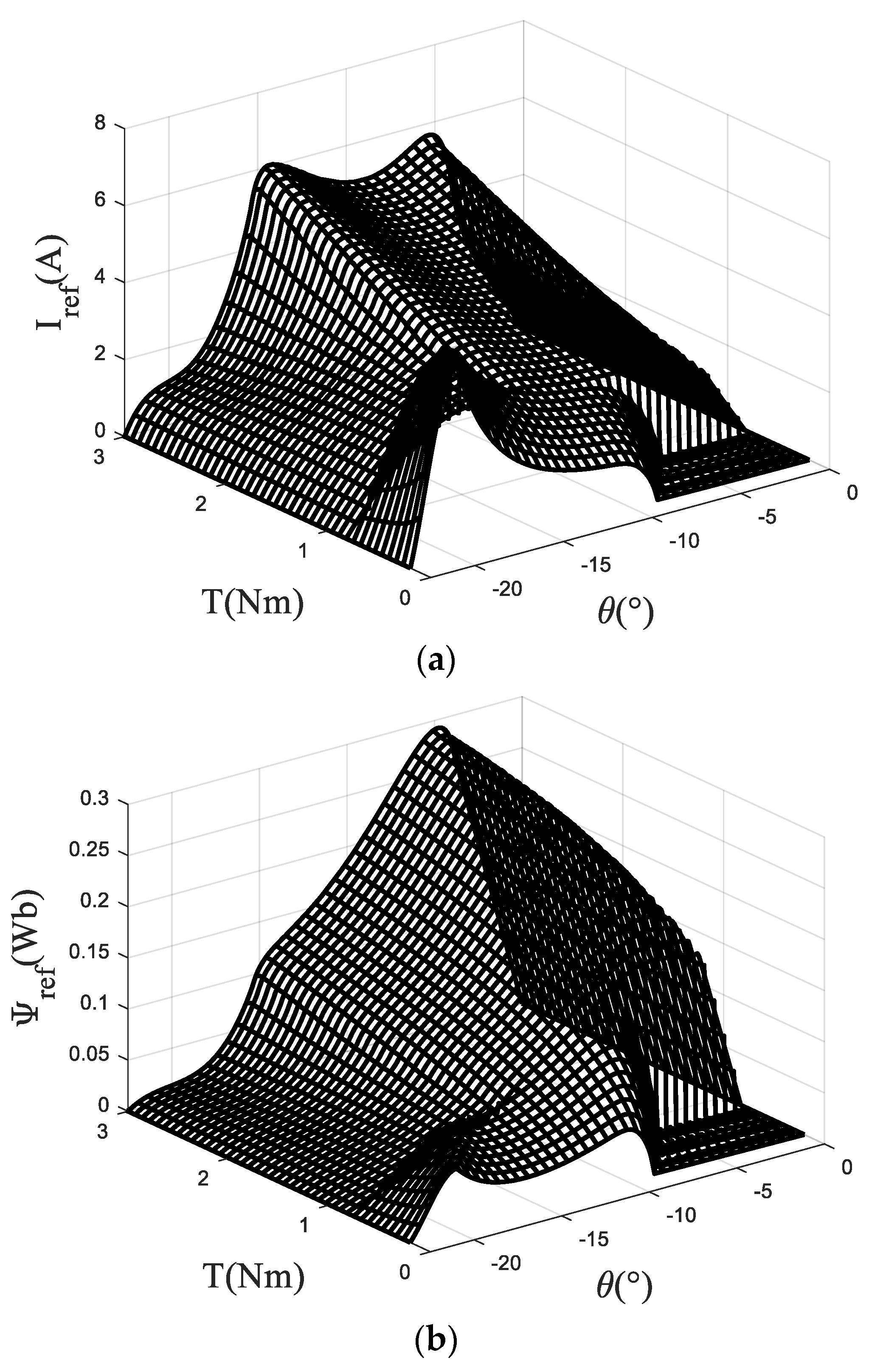
4. Verification and Analysis

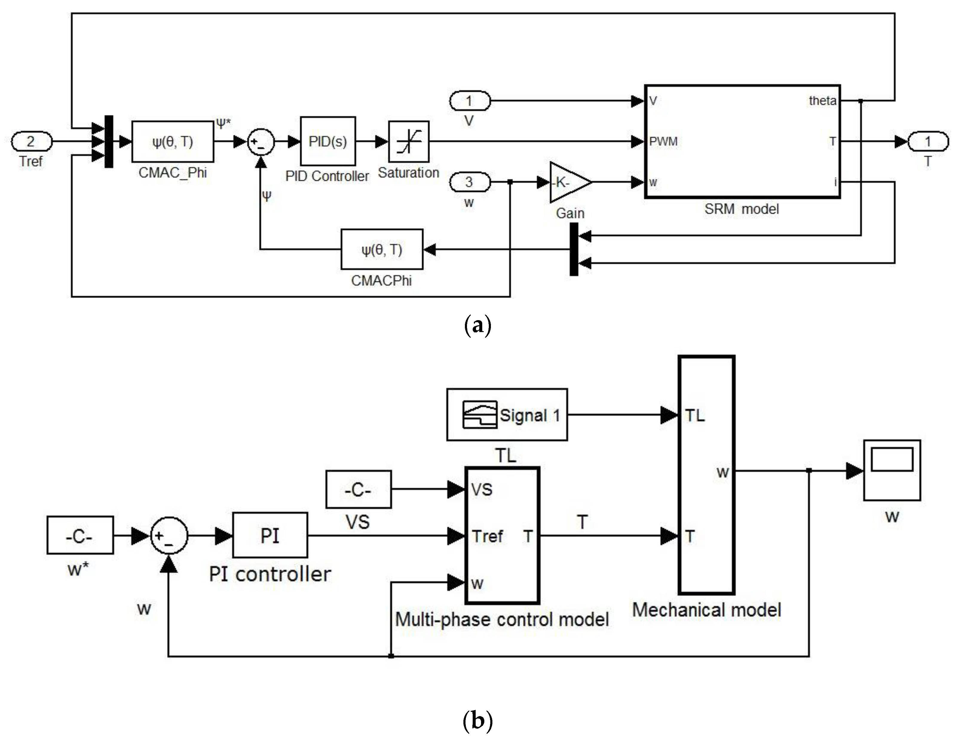
4.1. Description of Simulation Platform

The simulation verification of this chapter is realized on the simulation platform based on Matlab/Simulink. The single phase simulation model is depicted in Figure 9a. The single phase simulation model is divided into the system simulation model and control simulation model. The system simulation model describes the operation characteristics of SRM, which is depicted as SRM model in Figure 9a. The control simulation model is used to express the real-time control strategy of SRM, such as the PID control method. The application object is a 750 W, 8/6-pole four-phase SRM, and the overall simulation model of SRM including four phases is shown in Figure 9b. Specifically, the PI controller acts on the speed loop to obtain the control signal of reference torque. Then, combined with the proposed advanced torque plan method, the reference torque for each phase is obtained. Reference flux linkage for the corresponding phase is output by the torque inverse model which is called CMAC_Phi in Figure 9a. Next, the error of reference flux linkage and actual flux linkage is the input of the PID controller, while its output is PWM signals that act on the SRM model. The simulation step size is set to 2.5 μs, and the voltage PWM wave adjustment frequency is 20 kHz. The SRM drive system operates at a rotational speed of 1000 rpm and a desired torque of 2 Nm.

4.2. Analysis of the Simulated Result

The output results of the torque ripple suppression algorithm based on CMAC described in this manuscript are compared and analyzed with the traditional direct torque control results.
The traditional torque direct control does not include the steps of offline planning of torque and flux linkage but adopts a simple online torque distribution method. During normal operation of the SRM, one or two phases are on. When one phase is turned on, the control method is to make the expected torque of the opening phase equal to the total expected torque. If the opening phase is the j-th phase, there is Tj* = T*. When two phases are turned on at the same time, the online torque distribution method is shown in Table 1. The torque control flow chart based on this online torque distribution method is shown in previous section. The TSF module is planned according to Table 1. First, the reference torque distribution of the open phase is carried out based on the rotor angle position, opening angle, and closing angle parameters. The online TSF module performs the calculation of the online torque distribution and determines the opening phase through the judgement of the rotor position angle of the four phases. Then, the expected torque of each phase is calculated by the method in Table 1. The reference torque is compared with the torque measured in real time, and the error output is converted into a PWM signal by the PID controller and input to the power amplifier, and finally the torque control is realized. In the simulation, the phase with the rotor position angle in the range of [−30° −5°] is set as the open phase, and this range is selected to prevent the occurrence of braking torque. Figure 10 shows the simulation results under the traditional torque direct control strategy. From the simulation results, the maximum torque fluctuation is within 15% and the average torque fluctuation is within 5% under this strategy. The maximum current limit has been considered in the proposed planning method, and the smoothing of the flux linkage makes the expected value easier to achieve. However, the advantage of traditional method is that it does not require high accuracy for model and motor manufacturing and has strong online adaptability.
Figure 11 shows the simulation results of the SRM at a rotational speed of 1000 rpm and a reference torque of 2 Nm under the proposed torque ripple suppression method. From the simulation results, the strategy can well control the total torque so that it is stable near the expected value, and the maximum torque fluctuation is within 3% and the average torque fluctuation is within 1%. It is necessary to fully consider the ability of the PI controller to follow the signal when planning the torque. Therefore, the change of the flux linkage should be made as smooth as possible when planning the torque, which can enhance the signal following ability of the PI controller. Compared with the traditional torque direct control method, this method has a significant improvement in control accuracy, where the smoothness of the flux linkage change is taken into account in the torque planning. Since the flux linkage change rate is proportional to the power supply voltage and inversely proportional to the rotational speed, a better control effect can be obtained by directly acting on the PI controller on the difference between the current flux linkage and the expected flux linkage. Using the smooth flux linkage method to correct the original torque planning can make the planning signal easier to follow. Compared with the traditional torque control based on the online torque distribution method, the torque ripple generated by the torque control based on advance planning is greatly reduced, and the maximum torque ripple is reduced from 15% to 3%, which proves the effectiveness of the proposed method. However, this method depends on the model accuracy and the motor manufacturing accuracy, and the asymmetry of the motor manufacturing will lead to the amplification of the actual motor torque fluctuation.

5. Conclusions

This manuscript firstly establishes the electromagnetic characteristic model of an 8/6-pole four-phase SRM based on the pulse voltage ergodic response method, including flux linkage model, torque model, and torque inverse model, which fully considered the nonlinear property of the SRM. The CMAC method is adopted to complete the learning of each model. Then, the torque distribution function is planned based on the torque model to give the reference torque of each phase, in which the influence of actual operational conditions, such as the maximum current limit, has been considered. After the preprocessing operations, such as the smoothing of the flux linkage, the inverse torque model is used to realize the mapping of the reference torque to the reference flux linkage. Finally, the duty of each phase voltage PWM wave modulation is output based on the PID control theory. Torque control is achieved by adjusting the voltage across the windings of each phase. The proposed accurate model-based planning scheme is implemented on the simulation platform, in which the maximum torque fluctuation of the output results is reduced to within 3%, and the average error is reduced to within 1%. The effect is significantly improved compared with the traditional direct torque control method with the average torque ripple of 15%. The simulation results show that the proposed torque ripple suppression method based on the improved torque distribution function can effectively reduce the torque ripple.

Author Contributions

Conceptualization, X.L. and C.Z.; methodology, X.L.; software, X.L.; validation, X.L., C.Z. and L.Y.; formal analysis, X.L.; investigation, X.L.; resources, X.L.; data curation, X.L.; writing—original draft preparation, X.L.; writing—review and editing, X.L.; visualization, X.L.; supervision, J.Z.; project administration, J.Z.; funding acquisition, J.Z. All authors have read and agreed to the published version of the manuscript.

Funding

This research was funded by National Natural Science Foundation of China (grant number 51935007 and 52175512), and the Science and Technology Committee of Shanghai (grant number 19142203600).

Institutional Review Board Statement

Not applicable.

Informed Consent Statement

Not applicable.

Conflicts of Interest

The authors declare no conflict of interest.

References

  1. Takeno, M.; Chiba, A.; Hoshi, N.; Ogasawara, S.; Takemoto, M.; Rahman, M.A. Test Results and Torque Improvement of the 50-kW Switched Reluctance Motor Designed for Hybrid Electric Vehicles. IEEE Trans. Ind. Appl. 2012, 48, 1327–1334. [Google Scholar] [CrossRef]
  2. Ling, X.; Tao, J.; Li, B.; Qin, C.; Liu, C. A Multi-Physics Modeling-Based Vibration Prediction Method for Switched Reluctance Motors. Appl. Sci. 2019, 9, 4544. [Google Scholar] [CrossRef] [Green Version]
  3. Gan, C.; Wu, J.; Sun, Q.; Kong, W.; Li, H.; Hu, Y. A Review on Machine Topologies and Control Techniques for Low-Noise Switched Reluctance Motors in Electric Vehicle Applications. IEEE Access 2018, 6, 31430–31443. [Google Scholar] [CrossRef]
  4. Bostanci, E.; Moallem, M.; Parsapour, A.; Fahimi, B. Opportunities and challenges of switched reluctance motor drives for electric propulsion: A comparative study. IEEE Trans. Transp. Electrif. 2017, 3, 58–75. [Google Scholar] [CrossRef]
  5. Qin, C.; Xiao, D.; Tao, J.; Yu, H.; Jin, Y.; Sun, Y.; Liu, C. Concentrated velocity synchronous linear chirplet transform with application to robotic drilling chatter monitoring. Measurement 2022, 194, 111090. [Google Scholar] [CrossRef]
  6. Ullah, S.; McDonald, S.P.; Martin, R.; Benarous, M.; Atkinson, G.J. A permanent magnet assist, segmented rotor, switched reluctance drive for fault tolerant aerospace applications. IEEE Trans. Ind. Appl. 2019, 55, 298–305. [Google Scholar] [CrossRef] [Green Version]
  7. Bangcheng, H.; Zan, H.; Xu, Z.; Xu, L.; Tong, W.; Shiqiang, Z. Loss estimation, thermal analysis, and measurement of a large-scale turbomolecular pump with active magnetic bearings. IET Electr. Power Appl. 2020, 14, 1283–1290. [Google Scholar] [CrossRef]
  8. Ahmad, S.S.; Urabinahatti, C.; Prasad, K.N.V.; Narayanan, G. High-Switching-Frequency SiC Power Converter for High-Speed Switched Reluctance Machine. IEEE Trans. Ind. Appl. 2020, 57, 6069–6082. [Google Scholar] [CrossRef]
  9. Xu, Z.; Yu, Q.; Zhang, F. Design and Analysis of Asymmetric Rotor Pole Type Bearingless Switched Reluctance Motor. CES Trans. Electr. Mach. Syst. 2022, 6, 3–10. [Google Scholar] [CrossRef]
  10. Ghaffarpour, A.; Mirsalim, M. Split-Tooth Double-Rotor Permanent Magnet Switched Reluctance Motor. IEEE Trans. Transp. Electrif. 2022, 8, 2400–2411. [Google Scholar] [CrossRef]
  11. Han, N.; Sun, C.; Li, J.; Yang, H.; Han, S. Design and Characteristic Analysis of a New Dual-Stator Bearingless Switched Reluctance Motor. IEEE Access 2022, 10, 12941–12952. [Google Scholar] [CrossRef]
  12. Chen, H.-C.; Huang, B.-W. Integrated G2V/V2G Switched Reluctance Motor Drive with Sensing Only Switch-Bus Current. IEEE Trans. Power Electron. 2021, 36, 9372–9381. [Google Scholar] [CrossRef]
  13. Song, S.; Fang, G.; Hei, R.; Jiang, J.; Ma, R.; Liu, W. Torque Ripple and Efficiency Online Optimization of Switched Reluctance Machine Based on Torque per Ampere Characteristics. IEEE Trans. Power Electron. 2020, 35, 9608–9616. [Google Scholar] [CrossRef]
  14. Zhang, X.; Yang, Q.; Ma, M.; Lin, Z.; Yang, S. A Switched Reluctance Motor Torque Ripple Reduction Strategy with Deadbeat Current Control and Active Thermal Management. IEEE Trans. Veh. Technol. 2020, 69, 317–327. [Google Scholar] [CrossRef] [Green Version]
  15. Kondelaji, M.A.J.; Mirsalim, M. Segmented-Rotor Modular Switched Reluctance Motor with High Torque and Low Torque Ripple. IEEE Trans. Transp. Electrif. 2020, 6, 62–72. [Google Scholar] [CrossRef]
  16. Desaip, C.; Krishnamurthy, M.; Schofield, N.; Emadi, A. Novel Switched Reluctance Machine Configuration with Higher Number of Rotor Poles Than Stator Poles: Concept to Implementation. IEEE Trans. Ind. Electron. 2010, 57, 649–659. [Google Scholar] [CrossRef]
  17. Bilgin, B.; Emadi, A.; Krishnamurthy, M. Design Considerations for Switched Reluctance Machines with a Higher Number of Rotor Poles. IEEE Trans. Ind. Electron. 2012, 59, 3745–3756. [Google Scholar] [CrossRef]
  18. Sheth, N.K.; Rajagopal, K.R. Optimum pole arcs for a switched reluctance motor for higher torque with reduced ripple. IEEE Trans. Magn. 2003, 39, 3214–3216. [Google Scholar] [CrossRef]
  19. Choi, Y.K.; Yoon, H.S.; Koh, C.S. Pole-Shape Optimization of a Switched-Reluctance Motor for Torque Ripple Reduction. IEEE Trans. Magn. 2007, 43, 1797–1800. [Google Scholar] [CrossRef]
  20. Lee, D.; Pham, T.H.; Ahn, J. Design and Operation Characteristics of Four-Two Pole High-Speed SRM for Torque Ripple Reduction. IEEE Trans. Ind. Electron. 2013, 60, 3637–3643. [Google Scholar] [CrossRef]
  21. Lee, J.W.; Kim, H.S.; Kwon, B.I.; Kim, B.T. New rotor shape design for minimum torque ripple of SRM using FEM. IEEE Trans. Magn. 2004, 40, 754–757. [Google Scholar] [CrossRef]
  22. Kjaer, P.C.; Gribble, J.J.; Miller, T.J.E. High-grade control of switched reluctance machines. IEEE Trans. Ind. Appl. 1997, 33, 1585–1593. [Google Scholar] [CrossRef]
  23. Xue, X.D.; Cheng, K.W.E.; Lin, J.K.; Zhang, Z.; Luk, K.F.; Ng, T.W.; Cheung, N.C. Optimal Control Method of Motoring Operation for SRM Drives in Electric Vehicles. IEEE Trans. Veh. Technol. 2010, 59, 1191–1204. [Google Scholar] [CrossRef]
  24. Qin, C.; Shi, G.; Tao, J.; Yu, H.; Jin, Y.; Xiao, D.; Zhang, Z.; Liu, C. An adaptive hierarchical decomposition-based method for multi-step cutterhead torque forecast of shield machine. Mech. Syst. Signal Process. 2022, 175, 109148. [Google Scholar] [CrossRef]
  25. Mikail, R.; Husain, I.; Sozer, Y.; Islam, M.S.; Sebastian, T. Torque-Ripple Minimization of Switched Reluctance Machines Through Current Profiling. IEEE Trans. Ind. Appl. 2013, 49, 1258–1267. [Google Scholar] [CrossRef]
  26. Mikail, R.; Husain, I.; Islam, M.S.; Sozer, Y.; Sebastian, T. Four-Quadrant Torque Ripple Minimization of Switched Reluctance Machine Through Current Profiling with Mitigation of Rotor Eccentricity Problem and Sensor Errors. IEEE Trans. Ind. Appl. 2015, 51, 2097–2104. [Google Scholar] [CrossRef]
  27. Inderka, R.B.; De Doncker, R.W. High-dynamic direct average torque control for switched reluctance drives. IEEE Trans. Ind. Appl. 2003, 39, 1040–1045. [Google Scholar] [CrossRef]
  28. Klein-Hessling, A.; Hofmann, A.; Donckee, R.W.D. Direct instantaneous torque and force control: A control approach for switched reluctance machines. IET Electr. Power Appl. 2017, 11, 935–943. [Google Scholar] [CrossRef]
  29. Ye, J.; Bilgin, B.; Emadi, A. An Offline Torque Sharing Function for Torque Ripple Reduction in Switched Reluctance Motor Drives. IEEE Trans. Energy Convers. 2015, 30, 726–735. [Google Scholar] [CrossRef]
  30. Sun, Q.; Wu, J.; Gan, C.; Hu, Y.; Si, J. OCTSF for torque ripple minimisation in SRMs. IET Power Electron. 2016, 9, 2741–2750. [Google Scholar] [CrossRef]
  31. Xue, X.D.; Cheng, K.W.E.; Ho, S.L. Optimization and evaluation of torque sharing function for torque ripple minimization in switched reluctance motor drives. IEEE Trans. Power Electron. 2009, 49, 28–39. [Google Scholar] [CrossRef] [Green Version]
  32. Lin, Z.; Reay, D.; Williams, B.; He, X. High-performance current control for switched reluctance motors based on on-line estimated parameters. IET Electr. Power Appl. 2010, 4, 67–74. [Google Scholar] [CrossRef]
  33. Gobbi, R.; Ramar, K. Optimisation techniques for a hysteresis current controller to minimise torque ripple in switched reluctance motors. IET Electr. Power Appl. 2009, 3, 453–460. [Google Scholar] [CrossRef]
  34. Sahoo, S.K.; Panda, S.K.; Xu, J.X. Iterative learning-based high-performance current controller for switched reluctance motors. IEEE Trans. Energy Convers. 2004, 19, 491–498. [Google Scholar] [CrossRef]
  35. Sahoo, S.K.; Panda, S.K.; Xu, J.X. Indirect torque control of switched reluctance motors using iterative learning control. IEEE Trans. Power Electron. 2005, 20, 200–208. [Google Scholar] [CrossRef]
  36. Mir, S.; Islam, M.S.; Sebastian, T.; Husain, I. Fault-tolerant switched reluctance motor drive using adaptive fuzzy logic controller. IEEE Trans. Power Electron. 2004, 19, 289–295. [Google Scholar] [CrossRef]
  37. Reay, D.; Williams, B. Adapting CMAC neural networks with constrained LMS algorithm for efficient torque ripple reduction in switched reluctance motors. IEEE Trans. Control Syst. Technol. 1999, 7, 401–413. [Google Scholar]
Figure 1. Block diagram of TSF based torque control scheme.
Electronics 11 01552 g001
Figure 2. Torque control scheme based on TSF for a 4-phase SRM.
Electronics 11 01552 g002
Figure 3. 3D curve of flux linkage relative to the rotor angle and current.
Electronics 11 01552 g003
Figure 4. (a) inductance relative to the rotor angle and current (b) torque relative to the rotor angle and current.
Electronics 11 01552 g004
Figure 5. 2-layer memory structure of CMAC.
Electronics 11 01552 g005
Figure 6. Relationship between memory and errors.
Electronics 11 01552 g006
Figure 7. Torque plan waveform.
Electronics 11 01552 g007
Figure 8. Reference current and flux linkage under 1000 rpm (a) current (b) flux linkage.
Electronics 11 01552 g008
Figure 9. (a) Single phase simulation model (b) Overall simulation model of SRM.
Electronics 11 01552 g009
Figure 10. Results under traditional DTC (a) Torque (b) Current (c) Sum of torque.
Electronics 11 01552 g010aElectronics 11 01552 g010b
Figure 11. Results under modified TSF (a) Torque (b) Current (c) Sum of torque.
Electronics 11 01552 g011
Table 1. Simple torque online distribution.
Opening PhaseTorque
Plan
Torque Distribution
1&2T1 + T2 = T*T1* = T* − T2
T2* = T* − T1
2&3T2 + T3 = T*T2* = T* − T3
T3* = T* − T2
3&4T3 + T4= T*T3* = T* − T4
T4* = T* − T3
4&1T4 + T1 = T*T4* = T* − T1
T1* = T* − T4
Publisher’s Note: MDPI stays neutral with regard to jurisdictional claims in published maps and institutional affiliations.

