Article

Performance Evaluation of UAV-Based NOMA Networks with Hardware Impairment

1
Institute of Engineering and Technology, Thu Dau Mot University, Thu Dau Mot 75109, Vietnam
2
Department of Science and International Cooperation, Ho Chi Minh Minh City University of Transport, Ho Chi Minh City 72308, Vietnam
3
Faculty of Electronics Technology, Industrial University of Ho Chi Minh City (IUH), Ho Chi Minh City 71408, Vietnam
4
Department of Ecommerce Technology, School of Business Information Technology, University of Economics Ho Chi Minh City, Ho Chi Minh City 70000, Vietnam
*
Author to whom correspondence should be addressed.
Electronics 2022, 11(1), 94; https://doi.org/10.3390/electronics11010094
Submission received: 20 October 2021 / Revised: 12 December 2021 / Accepted: 24 December 2021 / Published: 28 December 2021
(This article belongs to the Section Networks)

Abstract

:
In this paper, we evaluate the outage performance of a non-orthogonal multiple access (NOMA)-enabled unmanned aerial vehicle (UAV) where two users on the ground are simultaneously served by a UAV for a spectral efficiency purpose. In practice, hardware impairments at the transceiver cause distortion noise, which results in the performance loss of wireless systems. As a consequence, hardware impairment is an unavoidable factor in the system design process. Hence, we take into account the effects of hardware impairment (HI) on the performance of the proposed system. In this setting, to evaluate the system performance, the closed-form expressions of the outage probability of two NOMA users and the ergodic capacity are derived as well as their asymptotic expressions for a high signal-to-noise ratio (SNR). Finally, based on Monte-Carlo simulations, we verify the analytical expressions and investigate the effects on the main system parameters, i.e., the transmit SNR and level of HI, on the system performance metrics. The results show that the performance for the near NOMA user is better than of that for the far NOMA user in the case of perfect hardware; however, in the case of hardware impairment, an inversion happens at a high transmit power of the UAV in terms of the ergodic capacity.

1. Introduction

In recent years, the use of UAVs in a wide range of civil and defense applications, such as search and rescue, cargo transport, and precision agriculture, has experienced unprecedented growth [1,2]. Further, two types of UAV, i.e., the rotary-wing type or fixed-wing type, are classified [3]. A UAV of the rotary-wing type equipped with multiple propellers can hover over fixed locations. A UAV of the fixed-wing type only flies in a path having a curvilinear form at a certain height, but cannot move along the vertical axis. Due to less power consumption of the fixed-wing type UAV compared with the rotary-wing type UAV, the fixed-wing type UAV is expected to be a potential solution for power-limited temporal wireless networks. Therefore, many deployment applications using UAVs in wireless communication networks have been studied, i.e., cooperative UAV networks [4], caching in wireless networks [5], and physical layer security [6].
Downlink non-orthogonal multiple access (NOMA) enables multiuser communication with the same frequency, which improves bandwidth utilization based on the design of the communication resources [7,8]. A few recent works have investigated the performance improvement of UAV-enabled communications systems based on the use of NOMA. In [9], the authors evaluated the outage probabilities of two ground NOMA users for a UAV base station communication system. The capacity region of a UAV support system with two ground users was studied; moreover, the trajectory and transmission power of the UAVs were jointly optimized [10]. The authors in [11] achieved the maximum sum-rate of a NOMA-based UAV by optimizing the power allocation and the UAV altitude. To improve the performance of a UAV-NOMA system, the authors in [12] designed a UAV deployment and power allocation scheme. A solution was proposed to maximize the number of users of a NOMA-enabled UAV while satisfying a quality service experience, by jointly optimizing the location design, admission control and power allocation [13]. An algorithm for minimizing the UAV mission completion time based on jointly optimizing the UAV trajectory and UAV ground base stations was designed in [14]. The energy efficiency of a mmWave-enabled NOMA-UAV system was maximized by optimizing the UAV position, hybrid precoding and power allocation in [15]. The UAV trajectory and the NOMA precoding were optimized to maximize the sum rate of a multiple user NOMA system in [16].
However, these works bypassed the problem of hardware impairment (HI) at the transmitters and receivers, while in practice the HI issue has a significant effect on system performance. HIs due to the phase noise of radio frequency components have been extensively investigated and modeled as additive distortion noise [17] and/or as a nonlinear polynomial multiplicative factor [18]. Considering HIs, a cognitive satellite–terrestrial network with multiple primary users was analyzed for outage performance in [19]. In [20], the outage probability and ergodic capacity under the effect of HIs on cooperative NOMA networks were derived. Over Rician fading channels, the effects of HIs on the NOMA cooperative duplex (FD) was examined [21]. However, the contents of these works did not mention UAVs in their systems, which was the motivation for us to study the influence of HIs on a UAV-based system.
In this paper, for more practical deployment, we consider a UAV system with regard to the HI issue where two ground users communicate with the UAV via a NOMA technique to improve the spectral usage.
The key contributions of this paper are listed as follows:
  • Unlike in [9,10,11,12,13,14,17,18,19,20,21], where HIs were ignored and UAVs were absent, respectively, we investigate the outage performance, i.e., outage probability and ergodic capacity, of a UAV-based system consisting of two NOMA users and based on formulating mathematical equations with coefficients representing HI. Moreover, this is the first time a UAV-based system with HI issues has been considered.
  • The performance of the proposed system is evaluated based on derivations of the closed-form expressions of the outage probability and ergodic capacity. To verify the derived expressions, we use Monte-Carlo simulations.
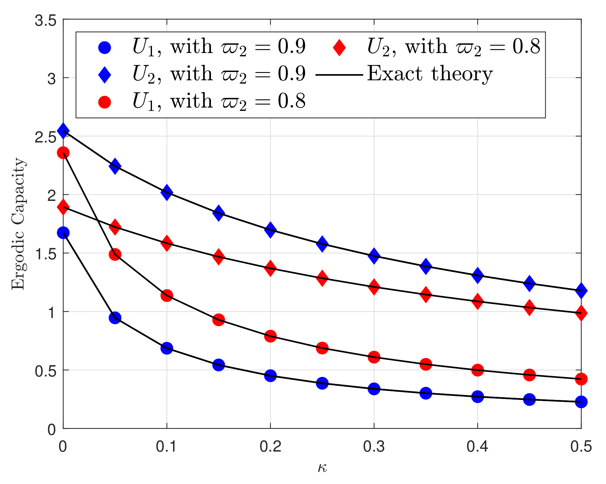
  • The effects of HI on the proposed system are carefully investigated to provide a guideline for UAV-based system design. The results show that under the effects of HI, in terms of the ergodic capacity, the performance of the far user is better than that of the near user at a high transmit power of the UAV.
In Section 2, we describe the system model. The performance analysis is presented in Section 3. Section 4 investigates the ergodic capacity of the system. Section 4 shows numerical results. Finally, a conclusion for the obtained results is presented in Section 5.

2. System Model

We consider an UAV-enabled system where the UAV communicates with two NOMA users, i.e., U 1 , U 2 , as shown in Figure 1.
Such a UAV maintains a constant velocity v, a circular trajectory of radius r, and an altitude h while flying. The angle of the UAV position in the UAV circle is denoted by φ , then the location of the UAV is represented as UAV ( r c o s φ , r s i n φ , h ) . As a result, the Euclidean distance between users U 1 and U 2 and the UAV may be calculated as follows [9]
d ¯ 1 = h 2 + r 2 + L 2 2 r L cos φ ,
d ¯ 2 = h 2 + r 2 + L 2 + 2 r L cos φ .
Finally, P L o S θ k and P N L o S θ k = 1 P L o S θ k represent the line-of-sight (LoS) and the non-line-of-sight (NLoS) probability, respectively. These last two quantities are obtained from the following formula (Equation (3) in [22]).
P L o S θ k = 1 1 + p e q θ k p , k 1 , 2
where p and q are constant values depending on the environment and θ k = arcsin H d k is the so-called elevation angle of the UAV with respect to each user (Equation (2) in [11]).
The corresponding observation at U i can be expressed as in [23]
y ¯ U i = h ¯ i d ¯ i α P ϖ 1 x ¯ 1 + P ϖ 2 x ¯ 2 + η ¯ U i + n ¯ U i , i 1 , 2 ,
where h ¯ i C N μ i , 2 σ 2 , α is the path loss exponent, η U i is the distortion noise caused by the UAV which is shown as η ¯ U i C N 0 , κ U 1 2 ϖ 1 P + κ U 2 2 ϖ 2 P in [24], and n ¯ U i C N 0 , N 0 is the additive complex white Gaussian noise (AWGN).
With the help of (3), the signal-to-interference plus noise-and-distortion ratio (SINDR) at U 1 for signal x ¯ 2 can be written as
γ ¯ U 1 , x ¯ 2 = ϖ 2 P d ¯ 1 α γ 1 N 0 + P d ¯ 1 α γ 1 κ U 2 2 ϖ 2 + 1 + κ U 1 2 ϖ 1 = ϖ 2 ρ d ¯ 1 α γ 1 1 + ρ d ¯ 1 α γ 1 κ U 2 2 ϖ 2 + 1 + κ U 1 2 ϖ 1 ,
where γ 1 = Δ h ¯ 1 2 and ρ = P P N 0 N 0 are the transmit SNRs at the NOMA users.
The signal-to-noise and distortion ratio (SNDR) of decoding x ¯ 1 at U 1 can be given as
γ ¯ U 1 , x ¯ 1 = ϖ 1 ρ d ¯ 1 α γ 1 1 + ρ d ¯ 1 α γ 1 κ U 2 2 ϖ 2 + κ U 1 2 ϖ 1 .
Next, U 2 can detect x ¯ 2 by treating x ¯ 1 as a noise, and the received SINR at U 2 is given by
γ ¯ U 2 , x ¯ 2 = ϖ 2 ρ d ¯ 2 α γ 2 1 + ρ d ¯ 2 α γ 2 κ U 2 2 ϖ 2 + 1 + κ U 1 2 ϖ 1 ,
where γ 2 = Δ h ¯ 2 2 .

3. Performance Analysis

In this section, we first introduce the channel model, then evaluate the performance of the proposed system based on two metrics, i.e., the outage probabilities of the users and the throughput system.

3.1. The Channel Model

In this subsection, the wireless channels between UAVs and ground users are expected to endure small-scale fading and large-scale route loss as in this work [25]. The presence of a robust line-of-sight (LoS) route characterizes a UAV-to-ground link channel in general. As a result, the Rician distribution is applied to a UAV-to-ground link channel with LoS and multipath scatterers at the ground receiver. As a result, a non-central chi-square distribution with two degrees of freedom is used to represent the probability distribution function (pdf) of the unordered squared channel gain γ i , i 1 , 2 [26].
f γ i 2 x = ϕ i e K i e ϕ i x I 0 2 K i ϕ i x ,
where ϕ i = 1 + K i 1 + K i Ω i Ω i , I 0 x , K i = Δ μ i 2 μ i 2 2 σ 2 2 σ 2 and Ω i = E γ i 2 = 1 are the first-order modified Bessel function in the zeroth-order, the Rician factor, and the normalized average fading power, respectively. Based on Equation (8.445) in [27], (7) can be rewritten by
f γ i 2 x = e K i e ϕ i x q = 0 K i q ϕ i k + 1 q ! Γ q + 1 x q ,
in which Γ x is the gamma function. The CDF (cumulative distribution function) is written as
F γ i 2 x = 1 Q 2 K i , 2 ϕ i x ,
where Q a , b is the Marcum Q-function of the first-order [26]. Using Equation (4.35) in [26], Equation (8.445) in [27] and after some manipulation, the CDF of the Rician channels can be rewritten as
F γ i 2 x = 1 e K 1 ϕ i x k = 0 q = 0 K i k + q ϕ i q x q q ! Γ k + q + 1 .

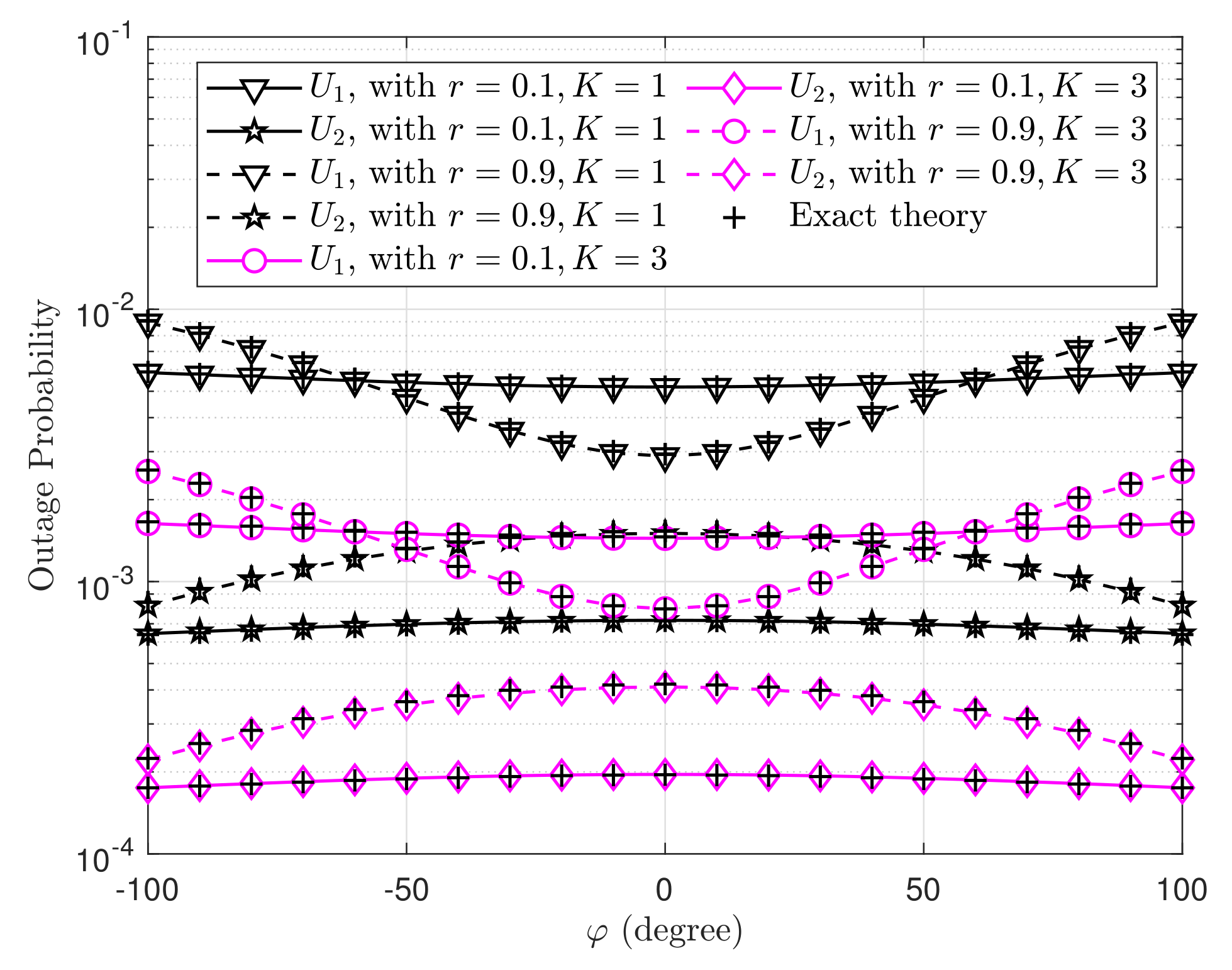
3.2. Outage Probability Analysis

Under the impacts of LoS and NLoS propagation, the outage probability (OP) of U 1 is determined as
P ¯ U 1 = P γ ¯ U 1 , x ¯ 2 < ε ¯ 2 γ ¯ U 1 , x ¯ 1 < ε ¯ 1 = 1 P γ ¯ U 1 , x ¯ 2 ε ¯ 2 , γ ¯ U 1 , x ¯ 1 ε ¯ 1 ,
where ε ¯ 2 = 2 2 R 2 1 , ε ¯ 1 = 2 2 R 1 1 .
Proposition 1.
The OP of U 1 is calculated as:
P ¯ U 1 = 1 A 1 A 2 ,
on the condition of ϖ 2 > ε ¯ 2 κ U 2 2 ϖ 2 + 1 + κ U 1 2 ϖ 1 and ϖ 1 > ε ¯ 1 κ U 2 2 ϖ 2 + κ U 1 2 ϖ 1 , where A 1 and A 2 are
A 1 = a P L o S θ 1 Q 2 K 1 , 2 ϕ 1 χ ˜ max = b P L o S θ 1 e K 1 ϕ 1 χ ˜ max k = 0 q = 0 K 1 k + q ϕ 1 q χ ˜ max q q ! Γ k + q + 1 ,
A 2 = a P N L o S θ 1 Q 2 K 1 , 2 ϕ 1 ω 1 χ ˜ max = b P N L o S θ 1 e K 1 ϕ 1 ω 1 χ ˜ max k = 0 q = 0 K 1 k + q ϕ 1 q χ ˜ max q q ! ω Γ k + q + 1 .
in which χ ¯ 2 = ε ¯ 2 ρ d ¯ 1 α ϖ 2 ε ¯ 2 κ U 2 2 ϖ 2 + 1 + κ U 1 2 ϖ 1 , χ ¯ 1 = ε ¯ 1 ρ d ¯ 1 α ϖ 1 ε ¯ 1 κ U 2 2 ϖ 2 + κ U 1 2 ϖ 1 , χ ¯ max = max χ ¯ 2 , χ ¯ 1 , P L o S θ k and P N L o S θ k are given in (2), respectively.
The OP of U 1 is a function dependent on power coefficients, i.e., ϖ 1 , ϖ 2 , the transmission rate of the two users, i.e., ε ¯ 1 ( R 1 ) , ε ¯ 2 ( R 2 ) , the LoS and NLoS propagation conditions, i.e., P L o S and P N L o S , and the hardware impairment levels at the users, i.e., κ U 1 and κ U 2 .
Proof. 
From (11) we have the OP of U 1 which is calculated by
P ¯ U 1 = P γ ¯ U 1 , x ¯ 2 < ε ¯ 2 γ ¯ U 1 , x ¯ 1 < ε ¯ 1 = 1 P γ ¯ U 1 , x ¯ 2 ε ¯ 2 , γ ¯ U 1 , x ¯ 1 ε ¯ 1 = 1 P γ 1 χ ¯ max ,
where χ ¯ 2 = ε ¯ 2 ρ d ¯ 1 α ϖ 2 ε ¯ 2 κ U 2 2 ϖ 2 + 1 + κ U 1 2 ϖ 1 , χ ¯ 1 = ε ¯ 1 ρ d ¯ 1 α ϖ 1 ε ¯ 1 κ U 2 2 ϖ 2 + κ U 1 2 ϖ 1 and χ ¯ max = max χ ¯ 2 , χ ¯ 1 .
We may rewrite (14) as (15) based on the conditional probability.
P ¯ U 1 = 1 χ ¯ max f γ 1 x d x .
Because each link’s propagation is dependent on the LoS or NLoS propagation as in Equation (18) in [28], (15) is given by
P ¯ U 1 = 1 P L o S θ 1 χ ¯ max f γ 1 x d x + P N L o S θ 1 χ ¯ max ω f γ 1 x d x = 1 P L o S θ 1 1 F γ 1 χ ¯ max P N L o S θ 1 1 F γ 1 χ ¯ max ω ,
in which ω = 1 for LoS propagation and ω < 1 for NLoS propagation as in [29]. Then, plugging (9) and (10) into (16), A 1 closed-form expression is obtained as (13a) and A 2 as (13b).
The proof is completed.  □
Next, from (6) the OP of U 2 is computed as follows:
P ¯ U 2 = 1 P γ ¯ U 2 , x ¯ 2 ε ¯ 2 = 1 P γ 2 χ ¯ 2 ,
where χ ¯ 2 = ε ¯ 2 ρ d ¯ 2 α ϖ 2 ε ¯ 2 κ U 2 2 ϖ 2 + 1 + κ U 1 2 ϖ 1 . Similarly, based on the solving of P ¯ U 1 , P ¯ U 2 can be achieved as
P ¯ U 2 = 1 A 3 A 4 ,
in which
A 3 = a P L o S θ 2 Q 2 K 2 , 2 ϕ 2 χ ¯ 2 = b P L o S θ 2 e K 2 ϕ 2 χ ¯ 2 k = 0 q = 0 K 2 k + q ϕ 2 q χ ¯ 2 q q ! Γ k + q + 1 ,
A 4 = a P N L o S θ 2 Q 2 K 2 , 2 ϕ 2 ω 1 χ ¯ 2 = b P N L o S θ 2 e K 2 ϕ 2 ω 1 χ ¯ 2 k = 0 q = 0 K 2 k + q ϕ 2 q χ ¯ 2 q q ! ω Γ k + q + 1 .
The OP of U 2 is a function dependent on power coefficients, i.e., ϖ 1 , ϖ 2 , its transmission rate, i.e., ε ¯ 2 ( R 2 ) , the LoS and NLoS propagation conditions, i.e., P L o S and P N L o S , and the hardware impairment levels at the users, i.e., κ U 1 and κ U 2 .

3.3. Asymptotic Analysis

Further, at high SNR ρ , we may simplify the Marcum Q-function by applying the Taylor series expansion Equation (13) in [9]
Q 2 K i , 2 ϕ i x 1 e K i ϕ i x .
Invoking (20) into (18) and (17) and we get the following result
P ¯ U 1 = 1 P L o S θ 1 1 e K 1 ϕ 1 χ ¯ max P N L o S θ 2 1 e K 1 ω 1 ϕ 1 χ ¯ max ,
and
P ¯ U 2 = 1 P L o S θ 2 1 e K 2 ϕ 2 χ ¯ 2 P N L o S θ 2 1 e K 2 ω 1 ϕ 2 χ ¯ 2 .

3.4. Throughput Analysis

Each user’s throughput may be computed as follows
τ ¯ U = 1 P ¯ U R , 1 , 2

4. Ergodic Capacity

The ergodic total rate is a significant indicator for performance evaluation when user rates are calculated based on their channel circumstances.
The ergodic capacity of U 2 is computed as
C ¯ 2 = E log 2 1 + γ ¯ U , x ¯ 2 .
Proposition 2.
The closed-form equation for ergodic capacity at user U 2 is as follows
C ¯ 2 = P L o S θ 2 k = 0 q = 0 K 2 k + q ϕ 2 q e K 2 q ! Γ k + q + 1 ln 2 1 ξ ¯ + ζ ¯ q G 1 , 2 2 , 1 ϕ 2 ξ ¯ + ζ ¯ 1 q 1 1 q 1 , 0 1 ζ ¯ q G 1 , 2 2 , 1 ϕ 2 ζ ¯ 1 q 1 1 q 1 , 0 + P N L o S θ 2 k = 0 q = 0 K 2 k + q ϕ 2 q e K 2 q ! Γ k + q + 1 ln 2 × 1 ω q ξ ¯ + ζ ¯ q G 1 , 2 2 , 1 ϕ 2 ω ξ ¯ + ζ ¯ 1 q 1 1 q 1 , 0 1 ω q ζ ¯ q G 1 , 2 2 , 1 ϕ 2 ω ζ ¯ 1 q 1 1 q 1 , 0 ,
where G p , q m , n . is the Meijer G-function in Equation (9.301) in [27], ξ ¯ = ρ d ¯ 2 α ϖ 2 and ζ ¯ = ρ d ¯ 2 α κ U 2 2 ϖ 2 + 1 + κ U 1 2 ϖ 1 . The ergodic capacity at U 2 is a function dependent on power coefficients, i.e., ϖ 1 , ϖ 2 , the LoS and NLoS propagation conditions, i.e., P L o S and P N L o S , and the hardware impairment levels at the users, i.e., κ U 1 and κ U 2 , ω = 1 represents LoS propagation and ω < 1 represents NLoS propagation.
Proof. 
We have (26) if we put (6) into it.
C ¯ 2 = E log 2 1 + γ ¯ U 2 , x ¯ 2 = 1 ln 2 0 1 1 + x 1 F γ ¯ U 2 , x ¯ 2 x d x = 1 ln 2 0 ξ ¯ ζ ¯ 1 1 + x 1 F γ 2 x ξ ¯ ζ ¯ x d x ,
where ξ ¯ = ρ d ¯ 2 α ϖ 2 and ζ ¯ = ρ d ¯ 2 α κ U 2 2 ϖ 2 + 1 + κ U 1 2 ϖ 1 . It’s worth noting that if x > ξ ¯ ζ ¯ , C ¯ 2 = 0 .
In (26), by the variable changing t x ξ ¯ ζ ¯ x and after a few steps, C ¯ 2 can then be written as
C ¯ 2 = 1 ln 2 0 1 t + ξ ¯ + ζ ¯ 1 1 t + ζ ¯ 1 1 F γ 2 t d t .
In (18), we have F γ 2 t which can be expressed as
F γ 2 t = 1 P L o S θ 2 Pr γ 2 > t P N L o S θ 2 Pr γ 2 > t ω = 1 P L o S θ 2 e K 2 ϕ 2 t k = 0 q = 0 K 2 k + q ϕ 2 q t q q ! Γ k + q + 1 P N L o S θ 2 e K 2 ω 1 ϕ 2 t k = 0 q = 0 K 2 k + q ϕ 2 q t q q ! ω q Γ k + q + 1 .
Submitting (28) into (27), C ¯ 2 is given as
C ¯ 2 = P L o S θ 2 k = 0 q = 0 K 2 k + q ϕ 2 q e K 2 q ! Γ k + q + 1 ln 2 0 e ϕ 2 t t q t + ξ ¯ + ζ ¯ 1 d t 0 e ϕ 2 t t q t + ζ ¯ 1 d t B 1 + P N L o S θ 2 k = 0 q = 0 K 2 k + q ϕ 2 q e K 2 q ! ω q Γ k + q + 1 ln 2 0 e ω 1 ϕ 2 t t q t + ξ ¯ + ζ ¯ 1 d t 0 e ω 1 ϕ 2 t t q t + ζ ¯ 1 d t B 2 .
Using the following methods, the exponential function is represented by Meijer’s G-function Equation (8.4.3.1) in [30]
e ϕ 2 t = G 0 , 1 1 , 0 ϕ 2 x 0 ,
e ϕ 2 ω t = G 0 , 1 1 , 0 ϕ 2 ω x 0 .
Submitting (30a) and (30b) into (29), B 1 and B 2 are given as
B 1 = 0 t q t + ξ ¯ + ζ ¯ 1 G 0 , 1 1 , 0 ϕ 2 t 0 d t 0 t q t + ζ ¯ 1 G 0 , 1 1 , 0 ϕ 2 t 0 d t ,
B 2 = 0 t q t + ξ ¯ + ζ ¯ 1 G 0 , 1 1 , 0 ϕ 2 ω x 0 d t 0 t q t + ζ ¯ 1 G 0 , 1 1 , 0 ϕ 2 ω x 0 d t .
In the next step, with the help of the Equation (7.811.5) in [27], B 1 and B 2 are given by
B 1 = 1 ξ ¯ + ζ ¯ q G 1 , 2 2 , 1 ϕ 2 ξ ¯ + ζ ¯ 1 q 1 1 q 1 , 0 1 ζ ¯ q G 1 , 2 2 , 1 ϕ 2 ζ ¯ 1 q 1 1 q 1 , 0 ,
B 2 = 1 ξ ¯ + ζ ¯ q G 1 , 2 2 , 1 ϕ 2 ω ξ ¯ + ζ ¯ 1 q 1 1 q 1 , 0 1 ζ ¯ q G 1 , 2 2 , 1 ϕ 2 ω ζ ¯ 1 q 1 1 q 1 , 0 .
Substituting the results of (32a) and (32b) into (29), we have the close-form ergodic capacity expression of U 2 , given as
C ¯ 2 = P L o S θ 2 k = 0 q = 0 K 2 k + q ϕ 2 q e K 2 q ! Γ k + q + 1 ln 2 1 ξ ¯ + ζ ¯ q G 1 , 2 2 , 1 ϕ 2 ξ ¯ + ζ ¯ 1 q 1 1 q 1 , 0 1 ζ ¯ q G 1 , 2 2 , 1 ϕ 2 ζ ¯ 1 q 1 1 q 1 , 0 + P N L o S θ 2 k = 0 q = 0 K 2 k + q ϕ 2 q e K 2 q ! Γ k + q + 1 ln 2 × 1 ω q ξ ¯ + ζ ¯ q G 1 , 2 2 , 1 ϕ 2 ω ξ ¯ + ζ ¯ 1 q 1 1 q 1 , 0 1 ω q ζ ¯ q G 1 , 2 2 , 1 ϕ 2 ω ζ ¯ 1 q 1 1 q 1 , 0 .
The proof is completed.  □
Next, the ergodic capacity of U 1 is given as
C ¯ 1 = E log 2 1 + γ ¯ U 1 , x ¯ 1 = 1 ln 2 0 1 x + 1 1 F γ ¯ U 1 , x ¯ 1 x d x = 1 ln 2 0 ξ ^ ζ ^ 1 x + 1 1 F γ 1 x ξ ^ ζ ^ x d x = t = x ξ ^ ζ ^ x 1 ln 2 0 1 t + ξ ^ + ζ ^ 1 1 t + ζ ^ 1 1 F γ 1 t d t ,
where ξ ^ = ρ d 1 α ϖ 1 and ζ ^ = ρ d 1 α κ D 2 2 ϖ 2 + κ D 1 2 ϖ 1 .
From (34), F γ 1 t is calculated by
F γ 1 u = 1 P L o S θ 1 Pr γ 1 u P N L o S θ 1 Pr γ 1 u ω = 1 P L o S θ 1 e K 1 ϕ 1 t k = 0 q = 0 K 1 k + q ϕ 1 q t q q ! Γ k + q + 1 P N L o S θ 1 e K 1 ω 1 ϕ 1 t k = 0 q = 0 K 1 k + q ϕ 1 q t q q ! ω q Γ k + q + 1 .
Submitting (35) into (34) and solving for C ¯ 2 , the close-form ergodic capacity at U 1 is attained as
C ¯ 1 = P L o S θ 1 k = 0 q = 0 K 1 k + q ϕ 1 q e K 1 q ! Γ k + q + 1 ln 2 1 ξ ^ + ζ ^ q G 1 , 2 2 , 1 ϕ 1 ξ ^ + ζ ^ 1 q 1 1 q 1 , 0 1 ζ ^ q G 1 , 2 2 , 1 ϕ 2 ζ ^ 1 q 1 1 q 1 , 0 + P N L o S θ 1 k = 0 q = 0 K 1 k + q ϕ 1 q e K 1 q ! Γ k + q + 1 ln 2 × 1 ω q ξ ^ + ζ ^ q G 1 , 2 2 , 1 ϕ 1 ω ξ ^ + ζ ^ 1 q 1 1 q 1 , 0 1 ω q ζ ^ q G 1 , 2 2 , 1 ϕ 2 ω ζ ^ 1 q 1 1 q 1 , 0 .
The ergodic capacity at U 1 is a function dependent on power coefficients, i.e., ϖ 1 , ϖ 2 , the LoS and NLoS propagation conditions, i.e., P L o S and P N L o S , and the hardware impairment levels at the users, i.e., κ U 1 and κ U 2 , ω = 1 represents LoS propagation and ω < 1 represents NLoS propagation.

5. Numerical Results

In this part, we assign κ = κ U 1 2 = κ U 1 2 , K = K 1 = K 2 and apply mathematical derivations to model the outage probability, which we then check with a Monte-Carlo simulation. The parameters utilized are listed in Table 1. Furthermore, the Monte-Carlo simulation is conducted 10 6 times to compare with the analytical results presented in the preceding section.
Figure 2 illustrates the effect of the Rician-K factor K on the system performance and user outage probabilities. The simulation results are matched by the generated analytical and asymptotic equations. At large values of average SNR, we can see that the analytical results are in good agreement with the simulation results and the asymptotic curves work quite well at high SNR regimes, which corroborates the accuracy of our derivation. The outage probabilities of both users tend to decrease linearly when the SNR increases. The figure shows that the performance of U 2 is better than that of U 1 . In addition, the outage probability increases as the value of K decreases. With the same K value, the outage probability of U 1 is always higher than that of U 2 .
Figure 3 illustrates the outage probabilities of the two users versus SNR with K = 2 , R 1 = 1 and R 2 = 0.5 under the effects of hardware impairment levels. It is observed that the higher the κ is, the higher is the outage probability. Moreover, U 2 always has a lower outage probability than U 1 regardless of the change of SNR and κ . In addition, the figure also shows that the outage probability of both users for the NOMA scheme is better than that for the OMA scheme.
Figure 4 plots the outage probability of two users versus ϖ 2 in cases of κ = 0.01 and ρ = 30 (dB). The figure shows that the outage probabilities of the two users change according to the variation of ϖ 2 . Specifically, the outage probability curves of U 1 first decrease in the ϖ 2 range from 0.5 to 0.6, then increase linearly in the ϖ 2 range from 0.6 to 0.9 and increase quickly in the ϖ 2 range from 0.9 to 1. The curves of the outage probability of U 2 decrease gradually in the overall range of ϖ 2 . When K increases, the outage probabilities for both users always decrease. With the same K value, U 1 has a higher outage probability than U 2 .
Figure 5 plots the outage probabilities of the two users versus φ with different r and K values. One can see from the figure that the outage probabilities of both U 1 and U 2 are almost constant for r = 0.1 , K = 1 , regardless of the change in φ . However, with r = 0.9 , K = 3 , the performances of the users have small changes. While the outage probability of U 1 decreases, that of U 2 increases in the φ range of −50 to 50 degrees. Especially, the outage probabilities of the two users reach maximum and minimum values at φ = 0 degrees.
Figure 6 plots the ergodic capacity versus SNR in the case of K = 5 and ω = 0.1 . One can see that the ergodic capacity of U 1 is higher than that of U 2 in the case of κ = 0 , i.e., with perfect hardware. However, when κ increases, herein κ = 0.1 and κ = 0.2 , the ergodic capacity of U 2 is higher than that of U 1 . This can be explained by understanding that when a hardware impairment level exists, only U 1 suffers the impacts of SNR. Besides, the higher the κ is, the lower the ergodic capacity is. Especially, the ergodic capacity for both users tends to be constant in the SNR range of 30 to 40 dB.
In Figure 7, we investigate the ergodic capacity of UAVs at various heights with a transmit SNR of 40 dB. The lines of U 1 and U 2 are overlapped with each other for the optimal target rate, as shown in this diagram. As shown in Figure 7, the ergodic capacity decreases as the height of the UAV grows, implying that when the distance between the UAV and ground user is too great, the UAV will be unable to communicate with the ground users with the supplied transmit power. This is because the level of hardware degradation grows as the distance between the UAV and the users increases, resulting in a decrease in the users’ ergodic capacity.
Finally, Figure 8 plots the ergodic capacity versus κ in the case of ϖ 2 = 0.8 or 0.9 . One can observe that the ergodic capacity of both users decreases gradually when the value of κ increases from 0.1 to 1. This shows that the hardware impairment level seriously affects the performance of the system. Additionally, the ergodic capacity also changes when ϖ 2 varies from 0.7 to 0.9. Specifically, the higher the ϖ 2 , the higher the ergodic capacity at U 2 .

6. Conclusions

In this paper, we evaluated a UAV-enabled system deploying NOMA under hardware impairment. The exact and asymptotic expressions of the outage probability of the NOMA users and the ergodic capacity were derived. The results showed that the hardware impairment significantly affects the performance of the users in terms of the outage probabilities and the egodic capacities of the users. Moreover, depending on the hardware impairment level, only U 1 suffers from transmit SNR. In particular, in the case of perfect hardware, the ergodic capacity of U 1 is higher than that of U 2 ; however, there is an inverse phenomenon, i.e., the ergodic capacity of U 2 is higher than that of U 1 , in imperfect hardware at a high SNR.

Author Contributions

Conceptualization, C.H.D., S.Q.N., C.-B.L. and N.T.V.K.; methodology, C.H.D. and S.Q.N.; formal analysis, C.-B.L. and N.T.V.K.; writing—original draft preparation, C.H.D.; writing—review and editing, S.Q.N.; funding acquisition, N.T.V.K. All authors have read and agreed to the published version of the manuscript.

Funding

The work of N.T.V. Khanh was supported by the University of Economics Ho Chi Minh City, Vietnam.

Conflicts of Interest

The authors declare no conflict of interest.

References

  1. Small Unmanned Aerial Vehicles for Aerial Imaging, Recreation and Aerial Games. Global Market Analysis and Forecast. Available online: https://www.prnewswire.com/news-releases/consumer-drones--small-unmanned-aerial-vehicles-for-aerial-imaging-recreation-and-aerial-games-global-market-analysis-and-forecasts-300291554.html (accessed on 19 October 2021).
  2. Liu, Y.; Dai, H.N.; Wang, Q.; Shukla, M.K.; Imran, M. Unmanned aerial vehicle for internet of everything: Opportunities and challenges. Comput. Commun. 2020, 155, 66–83. [Google Scholar] [CrossRef] [Green Version]
  3. Filippone, A. Flight Performance of Fixed and Rotary Wing Aircraft; American Institute of Aeronautics & Ast (AIAA): Reston, VA, USA, 2006. [Google Scholar]
  4. Shen, Y.; Pan, Z.; Liu, N.; You, X. Joint Design and Performance Analysis of a Full-Duplex UAV Legitimate Surveillance System. Electronics 2020, 9, 407. [Google Scholar] [CrossRef] [Green Version]
  5. Wei, M.; Chen, Y.; Ding, M. On the Performance of UAV-Aided Content Caching in Small-Cell Networks with Joint Transmission. Electronics 2021, 10, 1040. [Google Scholar] [CrossRef]
  6. Nguyen, P.X.; Nguyen, V.D.; Nguyen, H.V.; Shin, O.S. UAV-Assisted Secure Communications in Terrestrial Cognitive Radio Networks: Joint Power Control and 3D Trajectory Optimization. IEEE Trans. Veh. Technol. 2021, 70, 3298–3313. [Google Scholar] [CrossRef]
  7. Nguyen, T.T.; Vu, T.H.; Nguyen, T.V.; Costa, D.B.d.; Ho, C.D. Underlay Cognitive NOMA-Based Coordinated Direct and Relay Transmission. IEEE Wirel. Commun. Lett. 2021, 10, 854–858. [Google Scholar] [CrossRef]
  8. Nguyen, T.T.; Nguyen, T.V.; Vu, T.H.; Costa, D.B.d.; Ho, C.D. IoT-Based Coordinated Direct and Relay Transmission with Non-Orthogonal Multiple Access. IEEE Wirel. Commun. Lett. 2021, 10, 503–507. [Google Scholar] [CrossRef]
  9. Sharma, P.K.; Kim, D.I. UAV-Enabled Downlink Wireless System with Non-Orthogonal Multiple Access. In Proceedings of the 2017 IEEE Globecom Workshops (GC Wkshps), Singapore, 4–8 December 2017; pp. 1–6. [Google Scholar] [CrossRef]
  10. Wu, Q.; Xu, J.; Zhang, R. Capacity Characterization of UAV-Enabled Two-User Broadcast Channel. IEEE J. Sel. Areas Commun. 2018, 36, 1955–1971. [Google Scholar] [CrossRef] [Green Version]
  11. Sohail, M.F.; Leow, C.Y.; Won, S. Non-Orthogonal Multiple Access for Unmanned Aerial Vehicle Assisted Communication. IEEE Access 2018, 6, 22716–22727. [Google Scholar] [CrossRef]
  12. Liu, X.; Wang, J.; Zhao, N.; Chen, Y.; Zhang, S.; Ding, Z.; Yu, F.R. Placement and Power Allocation for NOMA-UAV Networks. IEEE Wirel. Commun. Lett. 2019, 8, 965–968. [Google Scholar] [CrossRef] [Green Version]
  13. Tang, R.; Cheng, J.; Cao, Z. Joint Placement Design, Admission Control, and Power Allocation for NOMA-Based UAV Systems. IEEE Wirel. Commun. Lett. 2020, 9, 385–388. [Google Scholar] [CrossRef]
  14. Mu, X.; Liu, Y.; Guo, L.; Lin, J. Non-Orthogonal Multiple Access for Air-to-Ground Communication. IEEE Trans. Commun. 2020, 68, 2934–2949. [Google Scholar] [CrossRef] [Green Version]
  15. Pang, X.; Tang, J.; Zhao, N.; Zhang, X.; Qian, Y. Energy-efficient design for mmWave-enabled NOMA-UAV networks. Sci. China Inf. Sci. 2021, 64, 1–14. [Google Scholar] [CrossRef]
  16. Zhao, N.; Pang, X.; Li, Z.; Chen, Y.; Li, F.; Ding, Z.; Alouini, M.S. Joint trajectory and precoding optimization for UAV-assisted NOMA networks. IEEE Trans. Commun. 2019, 67, 3723–3735. [Google Scholar] [CrossRef] [Green Version]
  17. Tung, N.T.; Nam, P.M.; Tin, P.T. Performance evaluation of a two-way relay network with energy harvesting and hardware noises. Digit. Commun. Netw. 2021, 7, 45–54. [Google Scholar] [CrossRef]
  18. Zhu, J.; Ng, D.W.K.; Wang, N.; Schober, R.; Bhargava, V.K. Analysis and Design of Secure Massive MIMO Systems in the Presence of Hardware Impairments. IEEE Trans. Wirel. Commun. 2017, 16, 2001–2016. [Google Scholar] [CrossRef] [Green Version]
  19. Guo, K.; An, K.; Zhang, B.; Huang, Y.; Zheng, G. Outage Analysis of Cognitive Hybrid Satellite-Terrestrial Networks with Hardware Impairments and Multi-Primary Users. IEEE Wirel. Commun. Lett. 2018, 7, 816–819. [Google Scholar] [CrossRef] [Green Version]
  20. Li, X.; Li, J.; Liu, Y.; Ding, Z.; Nallanathan, A. Residual Transceiver Hardware Impairments on Cooperative NOMA Networks. IEEE Trans. Wirel. Commun. 2020, 19, 680–695. [Google Scholar] [CrossRef]
  21. Deng, C.; Liu, M.; Li, X.; Liu, Y. Hardware Impairments Aware Full-Duplex NOMA Networks over Rician Fading Channels. IEEE Syst. J. 2021, 15, 2515–2518. [Google Scholar] [CrossRef]
  22. Masaracchia, A.; Nguyen, L.D.; Duong, T.Q.; Yin, C.; Dobre, O.A.; Garcia-Palacios, E. Energy-efficient and throughput fair resource allocation for ts-noma uav-assisted communications. IEEE Trans. Commun. 2020, 68, 7156–7169. [Google Scholar] [CrossRef]
  23. Li, X.; Wang, Q.; Liu, Y.; Tsiftsis, T.A.; Ding, Z.; Nallanathan, A. UAV-aided multi-way NOMA networks with residual hardware impairments. IEEE Wirel. Commun. Lett. 2020, 9, 1538–1542. [Google Scholar] [CrossRef]
  24. Tang, X.; An, K.; Guo, K.; Huang, Y. Outage analysis of non-orthogonal multiple access-based integrated satellite-terrestrial relay networks with hardware impairments. IEEE Access 2019, 7, 141258–141267. [Google Scholar] [CrossRef]
  25. Ono, F.; Ochiai, H.; Miura, R. A wireless relay network based on unmanned aircraft system with rate optimization. IEEE Trans. Wirel. Commun. 2016, 15, 7699–7708. [Google Scholar] [CrossRef]
  26. Simon, M.K.; Alouini, M.S. Digital Communication over Fading Channels; John Wiley & Sons: Hoboken, NJ, USA, 2005; Volume 95. [Google Scholar]
  27. Gradshteyn, I.S.; Ryzhik, I.M. Table of Integrals, Series and Products; Academic Press: Cambridge, MA, USA, 2014. [Google Scholar]
  28. Mozaffari, M.; Saad, W.; Bennis, M.; Debbah, M. Unmanned aerial vehicle with underlaid device-to-device communications: Performance and tradeoffs. IEEE Trans. Wirel. Commun. 2016, 15, 3949–3963. [Google Scholar] [CrossRef]
  29. Yang, S.; Deng, Y.; Tang, X.; Ding, Y.; Zhou, J. Energy efficiency optimization for UAV-assisted backscatter communications. IEEE Commun. Lett. 2019, 23, 2041–2045. [Google Scholar] [CrossRef] [Green Version]
  30. Prudnikov, A.P.; Brychkov, Y.A.; Marichev, O.I. Integrals and Series, Volume 3: More Special Functions; Gordon and Breach: New York, NY, USA; London, UK, 1986; Volume 55. [Google Scholar]
Figure 1. System model of UAV-enabled systems.
Electronics 11 00094 g001
Figure 2. Outage probabilities of the users with different K values.
Electronics 11 00094 g002
Figure 3. Outage probabilities of the users with K = 3 , R 1 = 1 and R 2 = 0.5 .
Electronics 11 00094 g003
Figure 4. Outage probabilities of the users versus the power coefficient with κ = 0.01 and ρ = 30 (dB).
Electronics 11 00094 g004
Figure 5. Outage probabilities of the users versus φ , with R 1 = R 2 = 1 , κ = 0.01 and ρ = 35 (dB).
Electronics 11 00094 g005
Figure 6. Ergodic capacity versus transmit SNR with K = 5 and ω = 0.1 .
Electronics 11 00094 g006
Figure 7. The ergodic capacity of U 1 and U 2 versus the altitude H of the UAV, with K = 10 , r = 0.9 , ω = 0.9 and ρ = 40 (dB).
Electronics 11 00094 g007
Figure 8. The ergodic capacities versus κ , with K = 2 , ω = 0.5 , r = 0.1 and ρ = 20 (dB).
Electronics 11 00094 g008
Table 1. Parameters.
Monte Carlo Simulations Repeated 10 6 Iterations
Target rates R 1 = 1.5 & R 2 = 1
Power splitting factors ϖ 2 = 0.9 & ϖ 1 = 0.1
The hardware impairments level κ = κ U 1 2 = κ U 1 2 = 0.01
Path-loss factor α = 2
The UAV’s altitude h = 1
The radius round the trajectory r = 0.1
The location of the ground users L = 1
The UAV’s location circle angle φ = 0
Environment parameters p = 4.886 & q = 0.429
Publisher’s Note: MDPI stays neutral with regard to jurisdictional claims in published maps and institutional affiliations.

