
Virtual Validation of an Automated Lane-Keeping System with an Extended Operational Design Domain


Abstract
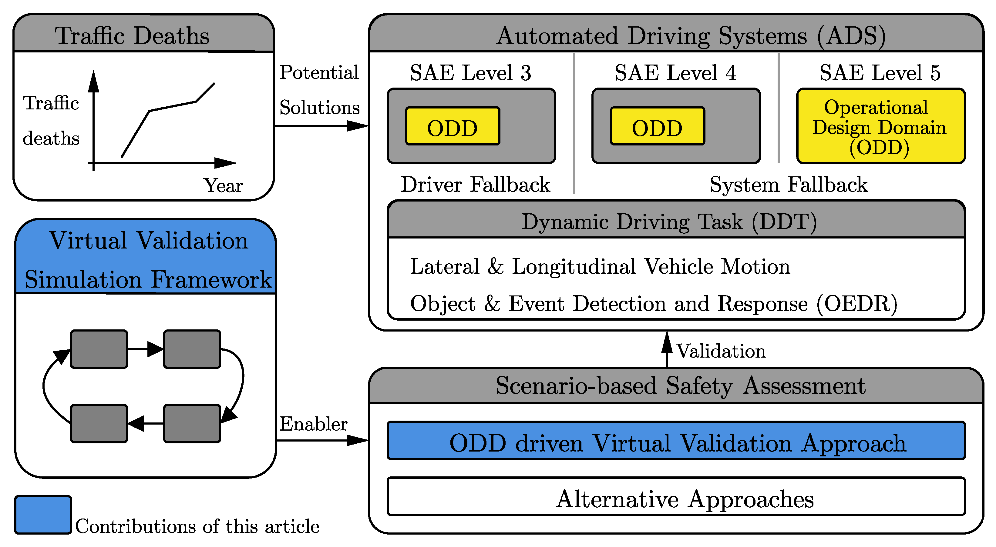
:1. Introduction
1.1. Safety Assessment for ADS
1.2. Virtual Testing of ADS for Safety Assessment
1.3. Scope of Work
- An ODD-driven virtual validation approach;
- A virtual validation simulation framework.
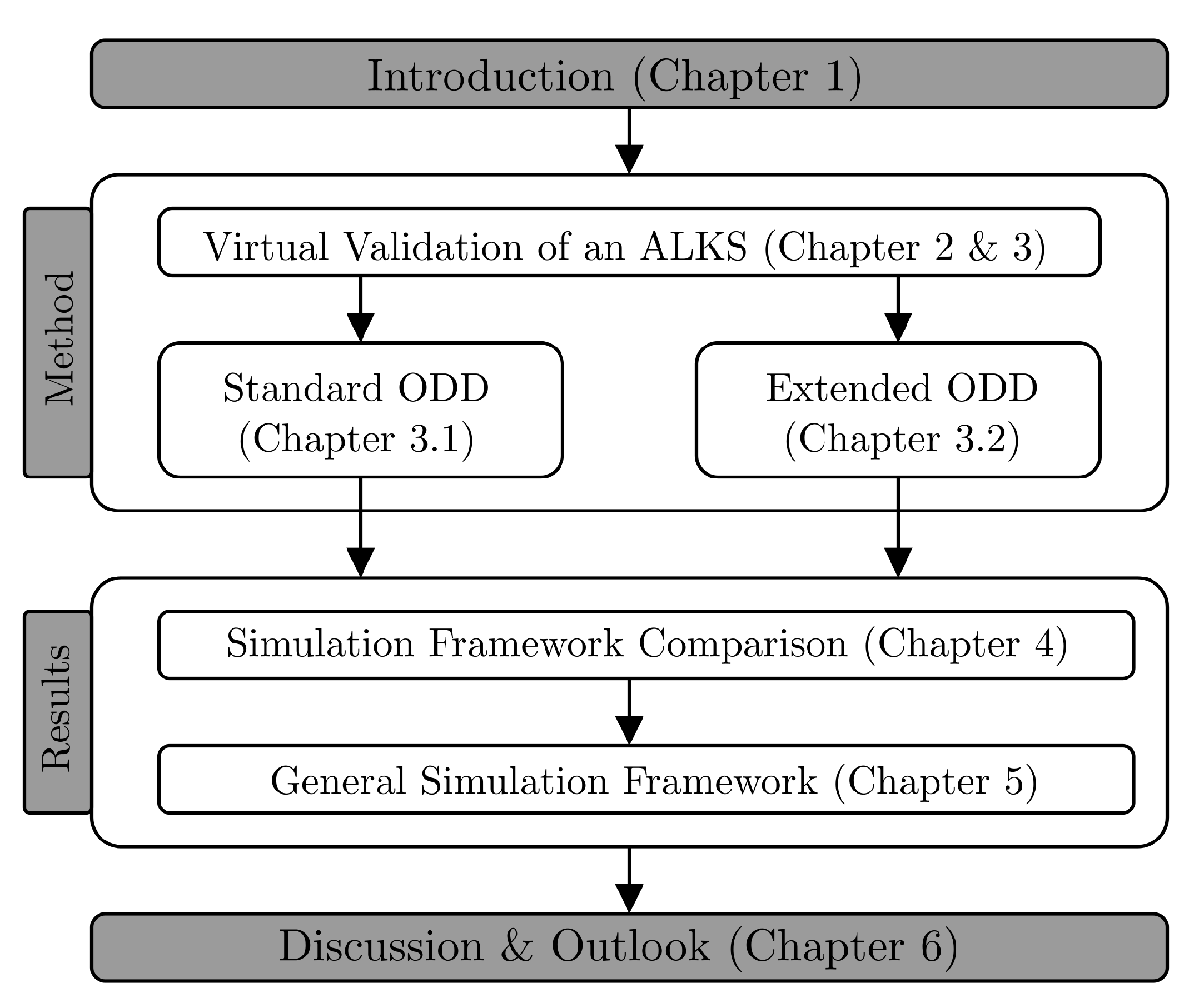
1.4. Structure of the Article
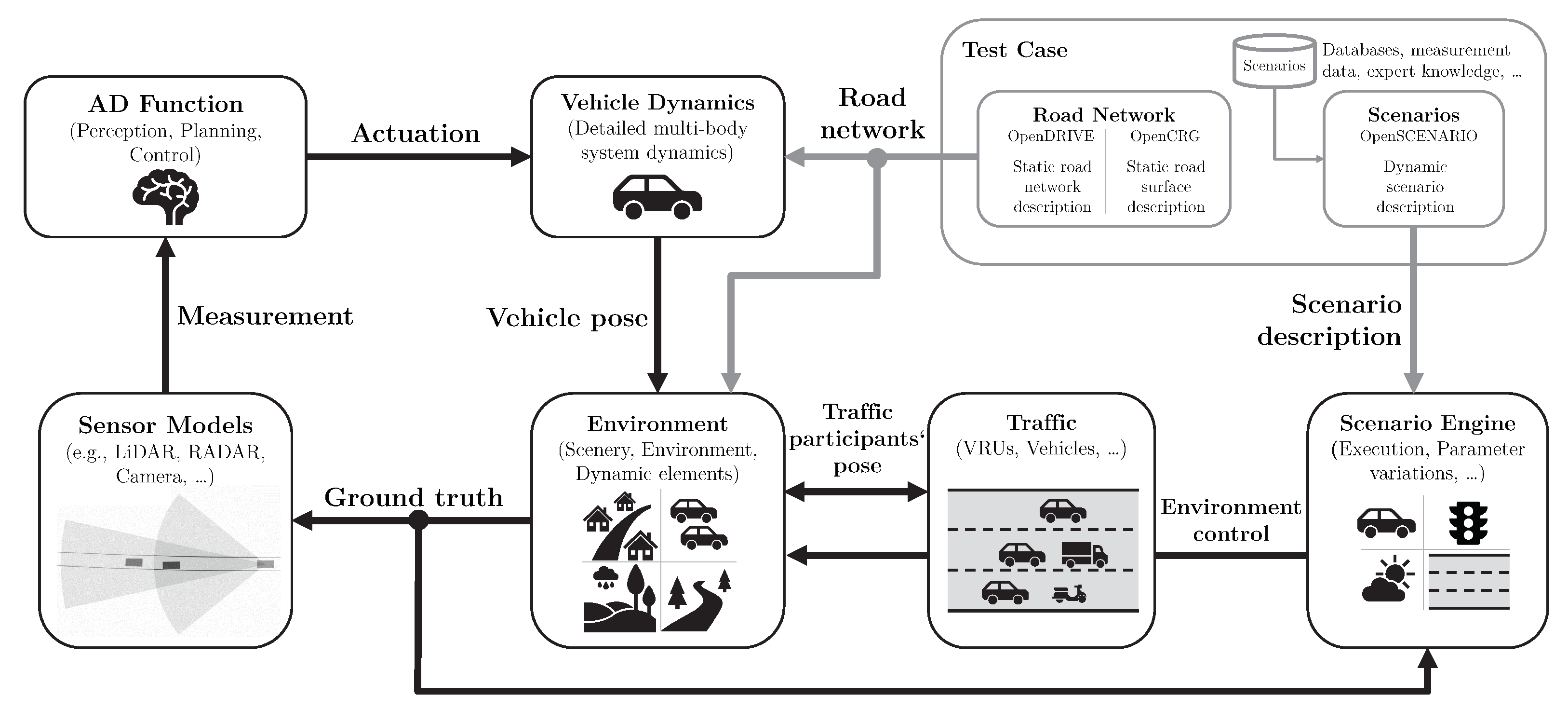
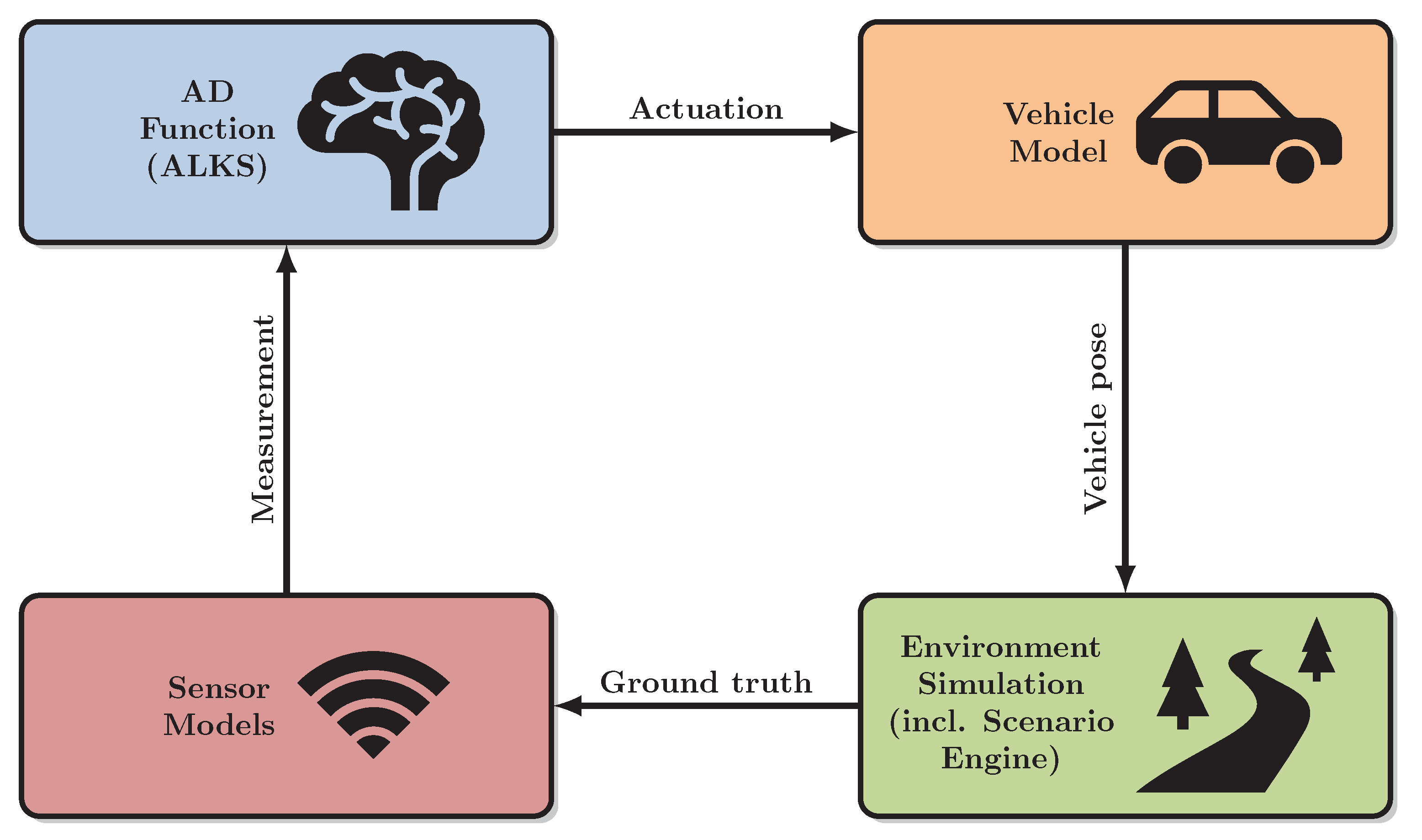
2. Virtual Validation of an ALKS
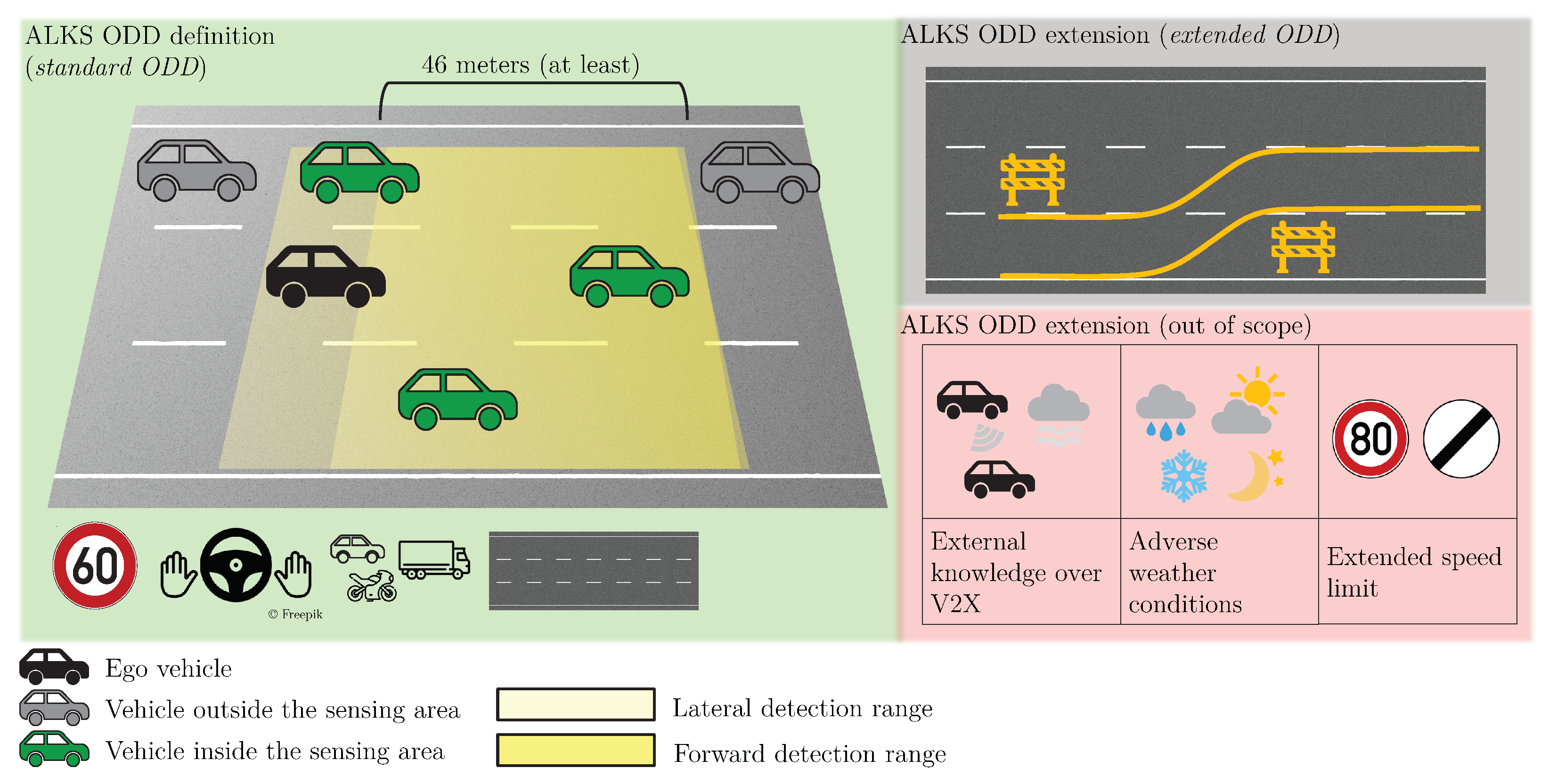
3. Virtual Validation of an ALKS with Varying ODD
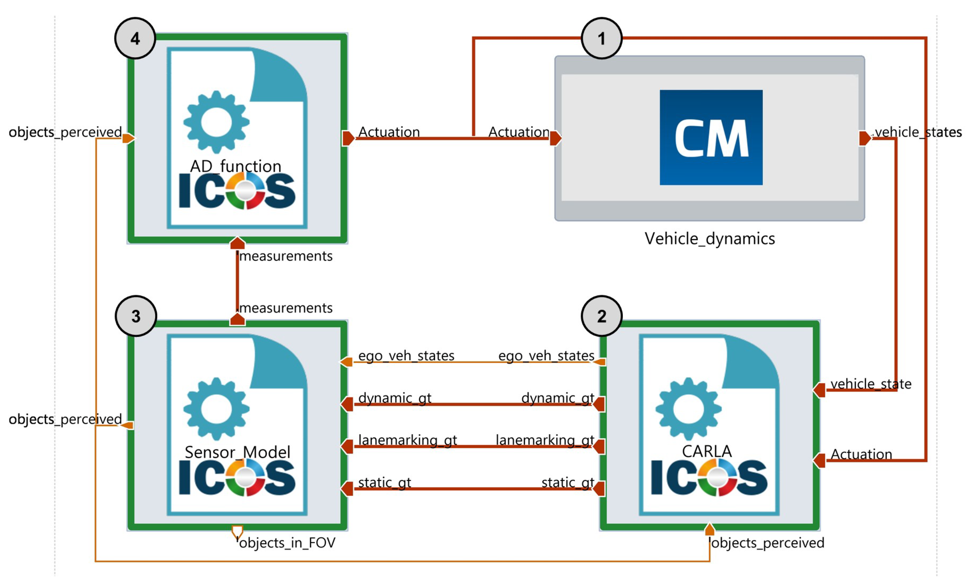
3.1. Virtual Validation Framework for the ALKS with a Standard ODD
3.1.1. AD Function
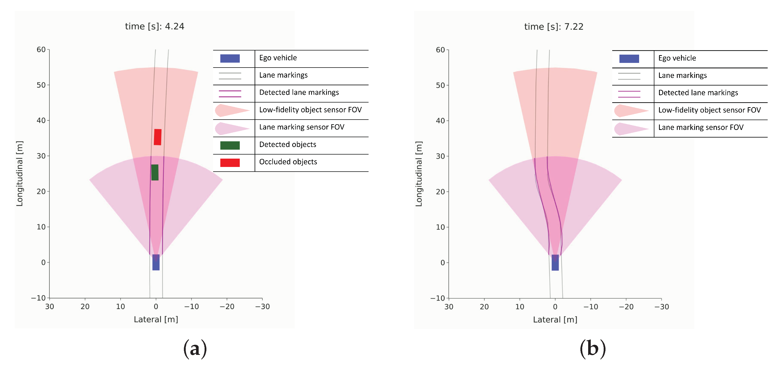
3.1.2. Sensor Models
3.1.3. Virtual Environment
3.1.4. Vehicle Dynamics
3.2. Virtual Validation Framework for the ALKS with an Extended ODD
3.2.1. AD Function & Sensor Models
3.2.2. Virtual Environment
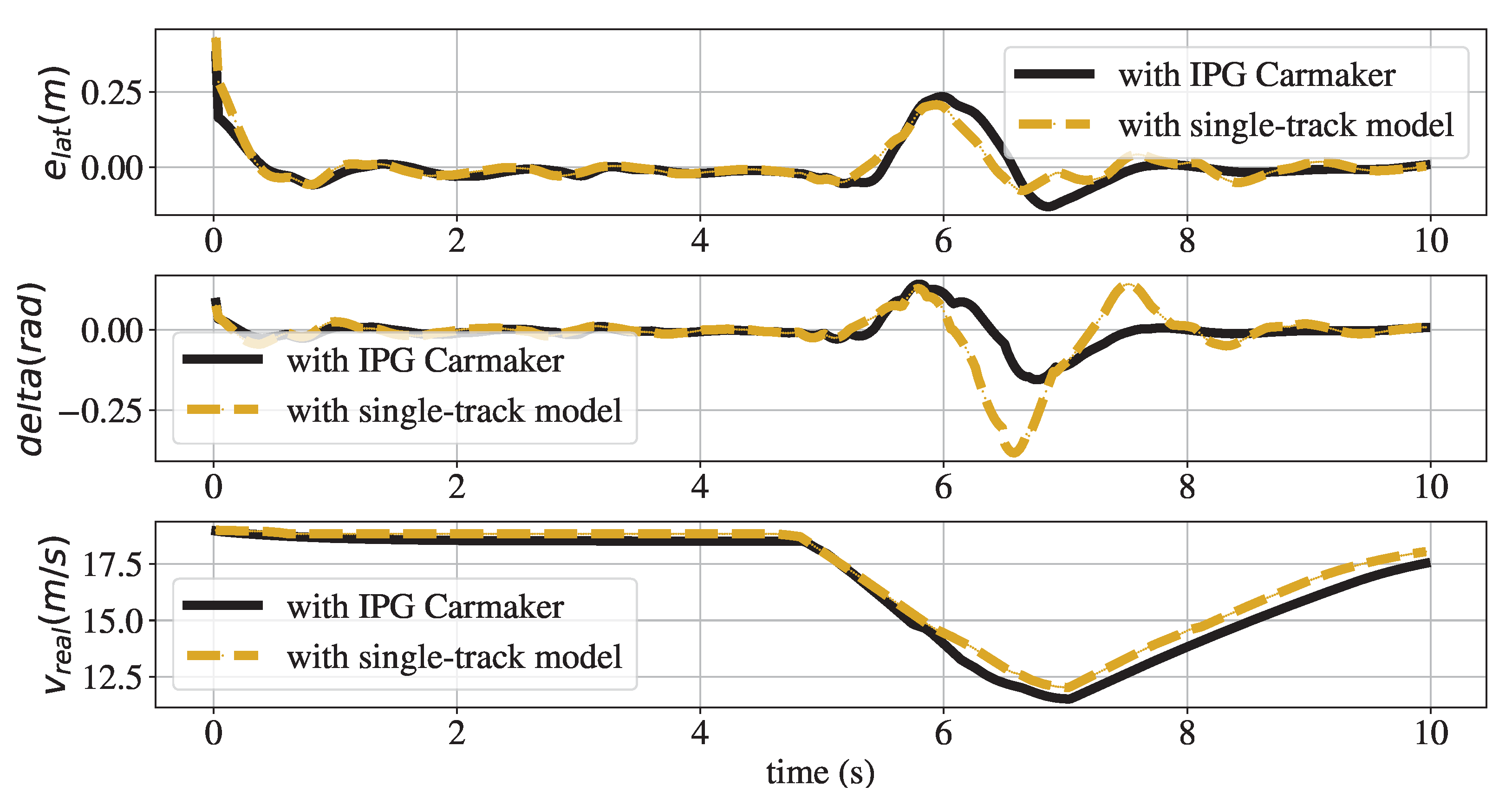
3.2.3. Vehicle Dynamics
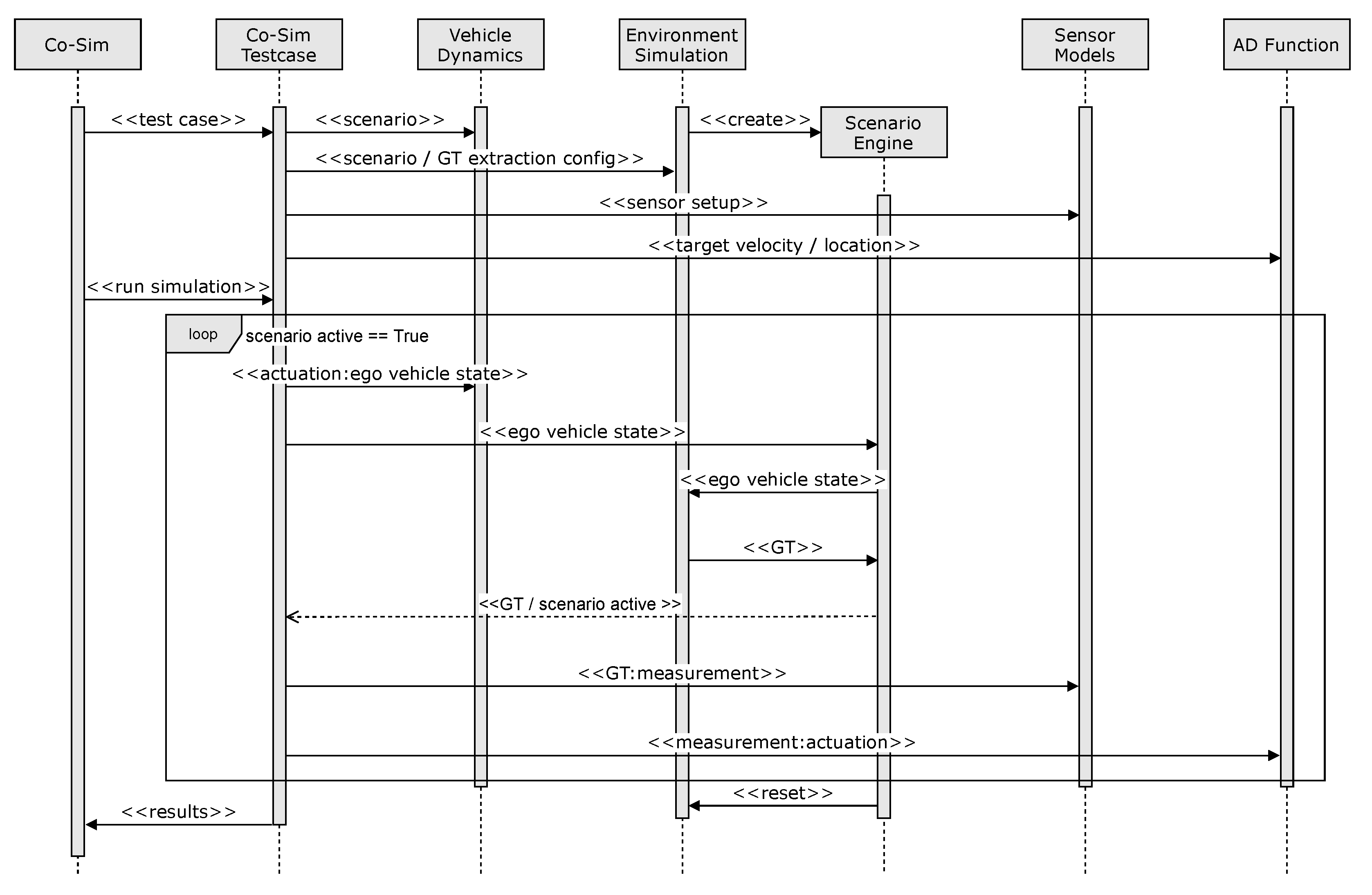
3.2.4. Implementation Details
| Algorithm 1: Simulation of a test case with the proposed co-simulation framework. |
 |
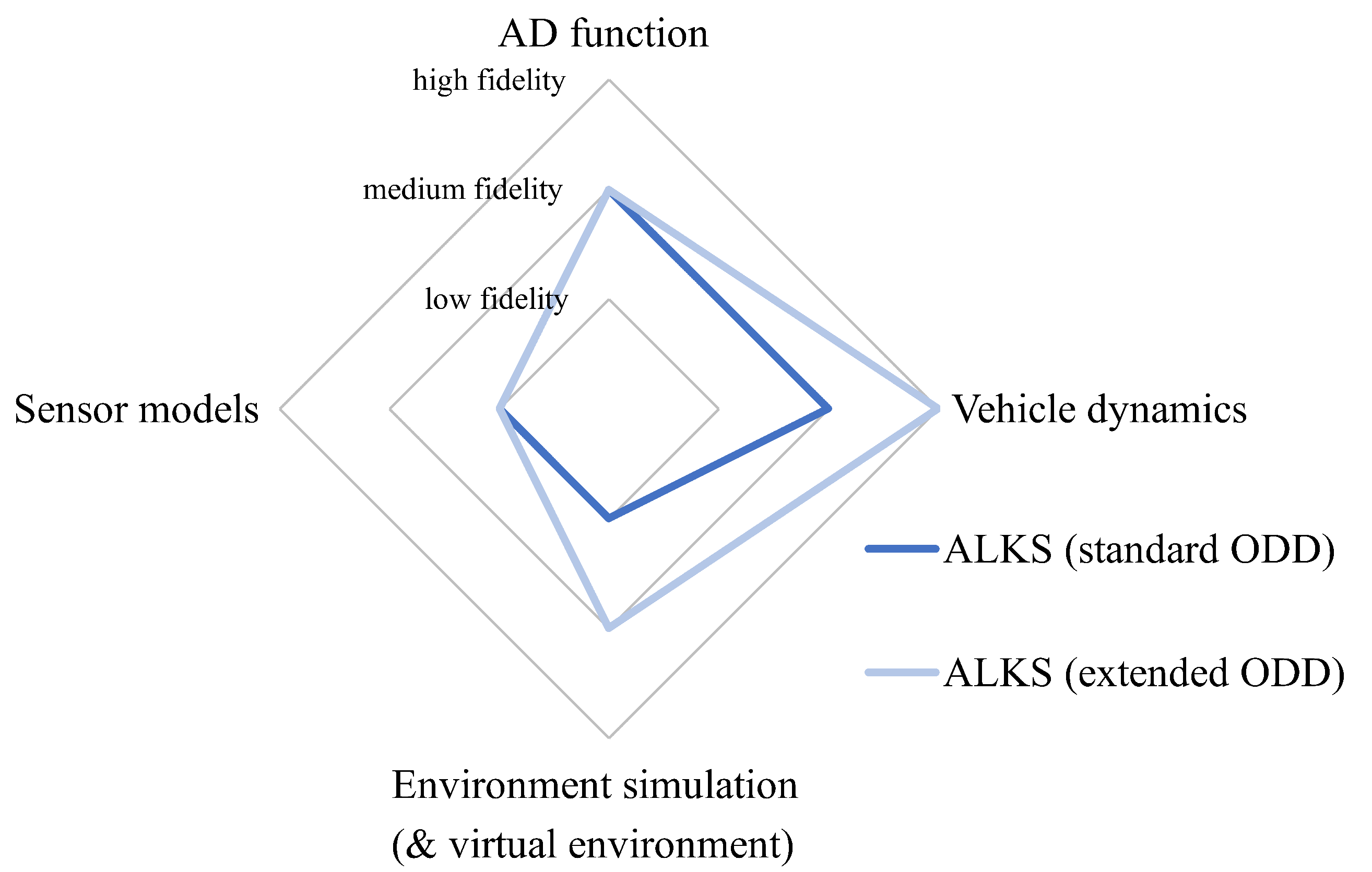
4. Simulation Framework Comparison for the ALKS with Varying ODD
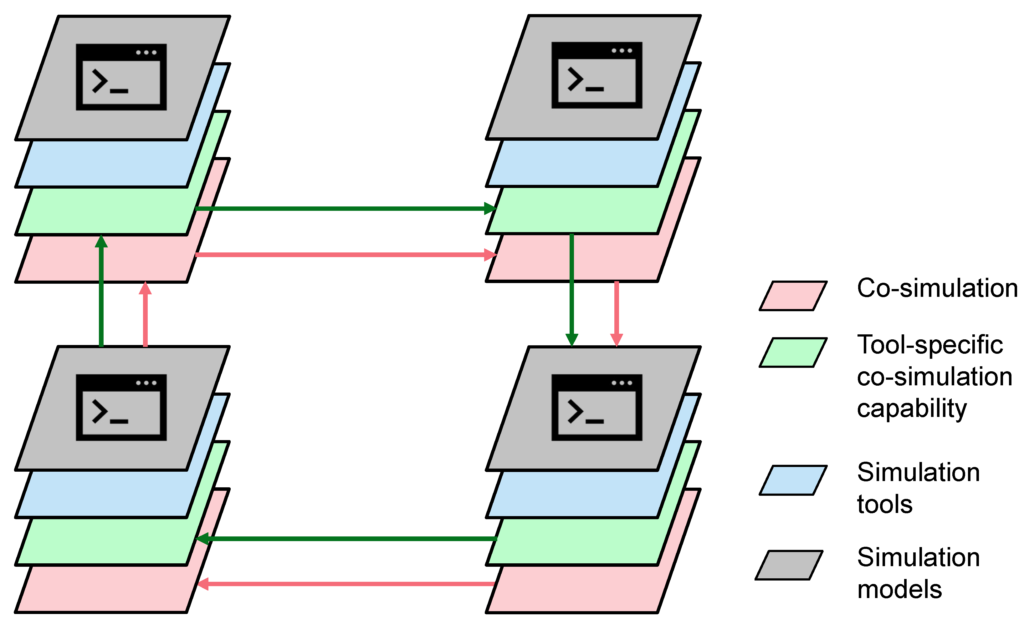
5. General Simulation Framework for Virtual Validation
6. Discussion and Outlook
Author Contributions
Funding
Acknowledgments
Conflicts of Interest
Abbreviations
| ALKS | Automated lane-keeping system |
| AD | Automated driving |
| ADS | Automated driving system |
| ACC | Adaptive cruise control |
| TP | Traffic participants |
| OEDR | Object and event detection and response |
| ODD | Operational design domain |
| FOV | Field of view |
| DOF | Degree of freedom |
| UN | United Nations |
| V2X | Vehicle-to-X (e.g., infrastructure) |
| ICOS | Independent co-simulation |
| XIL | X-in-the-loop |
| KPI | Key performance indicators |
| ZOH | Zero-order hold |
| SAE | Society of Automotive Engineers |
References
- World Health Organization. Global Status Report on Road Safety 2018: Summary; World Health Organization: Geneva, Switzerland, 2018; Available online: http://apps.who.int/iris/bitstream/handle/10665/277370/WHO-NMH-NVI-18.20-eng.pdf?ua=1 (accessed on 10 November 2021).
- Blumenthal, M.S.; Fraade-Blanar, L.; Best, R.; Irwin, J.L. Safe Enough: Approaches to Assessing Acceptable Safety for Automated Vehicles; Technical Report; RAND Corporation: Santa Monica, CA, USA, 2020. [Google Scholar]
- SAE J 3016—Taxonomy and Definitions for Terms Related to On-Road Motor Vehicle Automated Driving Systems; SAE International, On-Road Automated Driving (ORAD) Committee: Warrendale, PA, USA, 2021. [CrossRef]
- SaFAD. Safety First for Automated Driving. 2019. Available online: https://connectedautomateddriving.eu/mediaroom/framework-for-safe-automated-driving-systems/ (accessed on 17 November 2021).
- Schnelle, S.; Salaani, K.; Rao, S.J.; Barickman, F.S.; Elsasser, D. Review of Simulation Frameworks and Standards Related to Driving Scenarios; Number: DOT HS 812 815; National Highway Traffic Safety Administration: Washington, DC, USA, 2019.
- Watzenig, D.; Horn, M. (Eds.) Automated Driving: Safer and More Efficient Future Driving; Springer International Publishing: Cham, Switzerland, 2017. [Google Scholar] [CrossRef]
- Riedmaier, S.; Ponn, T.; Ludwig, D.; Schick, B.; Diermeyer, F. Survey on Scenario-Based Safety Assessment of Automated Vehicles. IEEE Access 2020, 8, 87456–87477. [Google Scholar] [CrossRef]
- Junietz, P.; Bonakdar, F.; Klamann, B.; Winner, H. Criticality Metric for the Safety Validation of Automated Driving using Model Predictive Trajectory Optimization. In Proceedings of the 2018 21st International Conference on Intelligent Transportation Systems (ITSC), Maui, HI, USA, 4–7 November 2018; IEEE: Maui, HI, USA, 2018; pp. 60–65. [Google Scholar] [CrossRef]
- Junietz, P.; Steininger, U.; Winner, H. Macroscopic Safety Requirements for Highly Automated Driving. Transp. Res. Rec. J. Transp. Res. Board 2019, 2673, 036119811982791. [Google Scholar] [CrossRef] [Green Version]
- Ulbrich, S.; Menzel, T.; Reschka, A.; Schuldt, F.; Maurer, M. Defining and Substantiating the Terms Scene, Situation, and Scenario for Automated Driving. In Proceedings of the 2015 IEEE 18th International Conference on Intelligent Transportation Systems, Gran Canaria, Spain, 15–18 September 2015; IEEE: Gran Canaria, Spain, 2015; pp. 982–988. [Google Scholar] [CrossRef]
- Scholtes, M.; Westhofen, L.; Turner, L.R.; Lotto, K.; Schuldes, M.; Weber, H.; Wagener, N.; Neurohr, C.; Bollmann, M.; Hiller, J.; et al. 6-Layer Model for a Structured Description and Categorization of Urban Traffic and Environment. IEEE Access 2021, 9, 59131–59147. [Google Scholar] [CrossRef]
- Bagschik, G.; Menzel, T.; Maurer, M. Ontology based Scene Creation for the Development of Automated Vehicles. In Proceedings of the 2018 IEEE Intelligent Vehicles Symposium (IV), Changshu, China, 26–30 June 2018; pp. 1813–1820. [Google Scholar] [CrossRef] [Green Version]
- JAMA; SAKURA. Automated Driving Safety Evaluation Framework Ver. 1.0-Guidelines for Safety Evaluation of Automated Driving Technology; Technical Report, Sakura Research Project: Kawaguchi, Japan, 2020. [Google Scholar]
- Antona-Makoshi, J.; Uchida, N.; Kitahara, E.; Ozawa, K. A Safety Assurance Process for Automated Driving Systems; ITS World Congress 2019: Singapore, 2019. [Google Scholar]
- PEGASUS. PEGASUS Method—An Overview. 2019. Available online: https://www.pegasusprojekt.de (accessed on 15 November 2021).
- Wagner, N.; Weissensteiner, P.; Coget, J.B.; Eckstein, L.; Bracquemond, A. Common Methodology for Data-Driven Scenario-Based Safety Assurance in the HEADSTART Project; ITS European Congress 2020: Los Angeles, CA, USA, 2020. [Google Scholar]
- ENABLE-S3. Testing and Validation of Highly Automated Systems—Summary of Results; 2019. Available online: https://enable-s3.eu (accessed on 13 November 2021).
- Thorn, E.; Kimmel, S.; Chaka, M. A Framework for Automated Driving System Testable Cases and Scenarios; Technical Report DOT HS 812 623; National Highway Traffic Safety Administration: Washington, DC, USA, 2018.
- U.S. Department of Transportation. Virtual Open Innovation Collaborative Environment for Safety; White Paper; Working Draft Version A; U.S. Department of Transportation: Washington, DC, USA, 2021.
- UK Law Commission and Scottish Law Commission. Automated Vehicles: Summary of Consultation Paper 3—A Regulatory Framework for Automated Vehicles. 2020. Available online: https://www.lawcom.gov.uk/project/automated-vehicles/ (accessed on 16 November 2021).
- Enterprise Singapore. Technical Reference for Autonomous Vehicles; Technical Report Part 1—4; Enterprise Singapore: Singapore, 2019. [Google Scholar]
- United Nations. UN Regulation on Automated Lane Keeping Systems is Milestone for Safe Introduction of Automated Vehicles in Traffic. Library Catalog. 2020. Available online: www.unece.org (accessed on 10 October 2021).
- Schlager, B.; Muckenhuber, S.; Schmidt, S.; Holzer, H.; Rott, R.; Maier, F.M.; Saad, K.; Kirchengast, M.; Stettinger, G.; Watzenig, D.; et al. State-of-the-Art Sensor Models for Virtual Testing of Advanced Driver Assistance Systems/Autonomous Driving Functions. SAE Int. J. Connect. Autom. Veh. 2020, 3, 233–261. [Google Scholar] [CrossRef]
- Hexagon. Virtual Test Drive—Enabling Safety Validation in Autonomous Driving and ADAS System Simulation. Available online: https://hexagon.com/ (accessed on 22 December 2021).
- aiMotive. aiSim 3.0—The World’s First ISO26262 ASIL-D Certified Simulator Tool. 2021. Available online: https://aimotive.com/aisim-3.0 (accessed on 22 December 2021).
- GmbH, I.A. CarMaker: Virtual Testing of Automobiles and Light-Duty Vehicles; IPG Automotive GmbH: Karlsruhe, Germany, 2020. [Google Scholar]
- Dosovitskiy, A.; Ros, G.; Codevilla, F.; Lopez, A.; Koltun, V. CARLA: An Open Urban Driving Simulator. arXiv 2017, arXiv:1711.03938. [Google Scholar]
- Riedmaier, S.; Danquah, B.; Schick, B.; Diermeyer, F. Unified Framework and Survey for Model Verification, Validation and Uncertainty Quantification. Arch. Comput. Methods Eng. 2021, 28, 2655–2688. [Google Scholar] [CrossRef]
- Gomes, C.; Thule, C.; Broman, D.; Larsen, P.G.; Vangheluwe, H. Co-simulation: State of the art. arXiv 2017, arXiv:1702.00686. [Google Scholar]
- Farah, H.; Bhusari, S.; van Gent, P.; Mullakkal Babu, F.A.; Morsink, P.; Happee, R.; van Arem, B. An Empirical Analysis to Assess the Operational Design Domain of Lane Keeping System Equipped Vehicles Combining Objective and Subjective Risk Measures. IEEE Trans. Intell. Transp. Syst. 2021, 22, 2589–2598. [Google Scholar] [CrossRef]
- Automated Vehicle Safety Consortium. AVSC Best Practice for Describing an Operational Design Domain: Conceptual Framework and Lexicon; Technical Report; SAE International: Warrendale, PA, USA, 2020; Available online: https://avsc.sae-itc.org/ (accessed on 22 December 2021).
- Gyllenhammar, M.; Johansson, R.; Warg, F.; Chen, D.; Heyn, H.M.; Sanfridson, M.; Söderberg, J.; Thorsén, A.; Ursing, S. Towards an Operational Design Domain That Supports the Safety Argumentation of an Automated Driving System. In Proceedings of the 10th European Congress on Embedded Real Time Software and Systems, Toulouse, France, 29–31 January 2020. [Google Scholar]
- Lee, C.W.; Nayeer, N.; Garcia, D.E.; Agrawal, A.; Liu, B. Identifying the Operational Design Domain for an Automated Driving System through Assessed Risk. In Proceedings of the 2020 IEEE Intelligent Vehicles Symposium (IV), Las Vegas, NV, USA, 19 October–13 November 2020; pp. 1317–1322. [Google Scholar] [CrossRef]
- PAS 1883:2020; BSI Standards Limited: London, UK, 2020.
- ISO/AWI 34503—Road Vehicles—Taxonomy for Operational Design Domain for Automated Driving Systems; International Organization for Standardization: Geneva, Switzerland. Available online: https://www.iso.org/standard/78952.html (accessed on 14 November 2021).
- Ladstädter, R.; Luley, P.; Ladstätter, S.; Mayer, H. UHD Mapping von Teststrecken für Automatisiertes Fahren; Dreiländertagung der DGPF, der OVG und der SGPF: Vienna, Austria, 2019. [Google Scholar]
- ASAM e.V. ASAM OpenDRIVE—Open Dynamic Road Information for Vehicle Environment. Available online: https://www.asam.net/standards/detail/opendrive/ (accessed on 22 December 2021).
- Mobileye. Mobileye—An Intel Company. Available online: https://www.mobileye.com/ (accessed on 22 December 2021).
- Weissensteiner, P.; Stettinger, G.; Tieber, K.; Rehrl, K. Virtual Risk Assessment for the Deployment of Autonomous Shuttles. Transp. Res. Rec. 2021, 2675, 131–140. [Google Scholar] [CrossRef]
- Weissensteiner, P.; Stettinger, G.; Tieber, K.; Watzenig, D.; Rehrl, K. Risk minimisation for autonomous shuttles in suburban environments based on virtual validation. In Proceedings of the ITS World Congress 2021, Hamburg, Germany, 11–15 October 2021. [Google Scholar] [CrossRef]
- Schmidt, S.; Schlager, B.; Muckenhuber, S.; Stark, R. Configurable Sensor Model Architecture for the Development of Automated Driving Systems. Sensors 2021, 21, 4687. [Google Scholar] [CrossRef] [PubMed]
- Siegl, S.; Ratz, S.; Düser, T.; Hettel, R. Vehicle-in-the-Loop am Prüfstand zur Validierung von ADAS/AD. ATZelektronik 2021, 16, 64–69. [Google Scholar] [CrossRef]
- Solmaz, S.; Holzinger, F. A Novel Testbench for Development, Calibration and Functional Testing of ADAS/AD Functions. In Proceedings of the 2019 IEEE International Conference on Connected Vehicles and Expo (ICCVE), Graz, Austria, 4–8 November 2019; IEEE: Graz, Austria, 2019; pp. 1–8. [Google Scholar] [CrossRef]
- Solmaz, S.; Holzinger, F.; Mischinger, M.; Rudigier, M.; Reckenzaun, J. Novel Hybrid-Testing Paradigms for Automated Vehicle and ADAS Function Development. In Towards Connected and Autonomous Vehicle Highways; Hamid, U.Z.A., Al-Turjman, F., Eds.; Series Title: EAI/Springer Innovations in Communication and Computing; Springer International Publishing: Cham, Switzerland, 2021; pp. 193–228. [Google Scholar] [CrossRef]
- Hallerbach, S. Simulation-Based Testing of Cooperative and Automated Vehicles; University of Oldenburg, Department of Computer Science: Oldenburg, Germany, 2020. [Google Scholar]
- Nalic, D.; Pandurevic, A.; Eichberger, A.; Rogic, B. Design and Implementation of a Co-Simulation Framework for Testing of Automated Driving Systems. Sustainability 2020, 12, 10476. [Google Scholar] [CrossRef]
- Nalic, D.; Eichberger, A.; Hanzl, G.; Fellendorf, M.; Rogic, B. Development of a Co-Simulation Framework for Systematic Generation of Scenarios for Testing and Validation of Automated Driving Systems*. In Proceedings of the 2019 IEEE Intelligent Transportation Systems Conference (ITSC), Auckland, New Zealand, 27–30 October 2019; pp. 1895–1901. [Google Scholar] [CrossRef]
- Nalic, D.; Pandurevic, A.; Eichberger, A.; Rogic, B. Software Framework for Testing of Automated Driving Systems in a Dynamic Traffic Environment. arXiv 2020, arXiv:2011.05798. [Google Scholar]
- Nalic, D.; Li, H.; Eichberger, A.; Wellershaus, C.; Pandurevic, A.; Rogic, B. Stress Testing Method for Scenario-Based Testing of Automated Driving Systems. IEEE Access 2020, 8, 224974–224984. [Google Scholar] [CrossRef]
- Lopez, P.A.; Behrisch, M.; Bieker-Walz, L.; Erdmann, J.; Flötteröd, Y.P.; Hilbrich, R.; Lücken, L.; Rummel, J.; Wagner, P.; Wießner, E. Microscopic traffic simulation using SUMO. In Proceedings of the 21st IEEE International Conference on Intelligent Transportation Systems, Maui, HI, USA, 4–7 November 2018; IEEE: New York City, NY, USA, 2018. [Google Scholar] [CrossRef] [Green Version]
- von Neumann-Cosel, K. Virtual Test Drive–Simulation umfeldbasierter Fahrzeugfunktionen; Technical University of Munich, Faculty of Computer Science: Munich, Germany, 2014. [Google Scholar]
- ASAM e.V. ASAM OpenSCENARIO; Volume 1.1.0.; ASAM e.V.: Hoehenkirchen, Germany, 2021; Available online: https://www.asam.net/standards/detail/openscenario/ (accessed on 22 December 2021).
- ASAM e.V. ASAM OpenCRG—Open Curved Regular Grid; Volume 1.2.0.; ASAM e.V.: Hoehenkirchen, Germany, 2021; Available online: https://www.asam.net/standards/detail/opencrg/ (accessed on 22 December 2021).
- van Driesten, C.; Schaller, T. Overall Approach to Standardize AD Sensor Interfaces: Simulation and Real Vehicle. In Fahrerassistenzsysteme 2018; Bertram, T., Ed.; Springer Fachmedien Wiesbaden: Wiesbaden, Germnay, 2019; pp. 47–55. [Google Scholar] [CrossRef]
- Marko, N.; Ruebsam, J.; Biehn, A.; Schneider, H. Scenario-based Testing of ADAS—Integration of the Open Simulation Interface into Co-simulation for Function Validation. In Proceedings of the 9th International Conference on Simulation and Modeling Methodologies, Technologies and Applications, SIMULTECH 2019, Prague, Czech Republic, 29–31 July 2019; SCITEPRESS—Science and Technology Publications, Lda.: Setubal, Portugal, 2019; pp. 255–262. [Google Scholar] [CrossRef]
- ASAM e.V. ASAM OSI—Open Simulation Interface; Volume 3.3.0.; ASAM e.V.: Hoehenkirchen, Germany, 2021; Available online: https://www.asam.net/standards/detail/osi/ (accessed on 22 December 2021).
- Stolz, M.; Nestlinger, G. Fast generic sensor models for testing highly automated vehicles in simulation. Elektrotechnik Informationstechnik 2018, 135, 365–369. [Google Scholar] [CrossRef] [Green Version]
- Genser, S.; Muckenhuber, S.; Solmaz, S.; Reckenzaun, J. Development and Experimental Validation of an Intelligent Camera Model for Automated Driving. Sensors 2021, 21, 7583. [Google Scholar] [CrossRef]
- Hirsenkorn, N.; Hanke, T.; Rauch, A.; Dehlink, B.; Rasshofer, R.; Biebl, E. A non-parametric approach for modeling sensor behavior. In Proceedings of the 2015 16th International Radar Symposium (IRS), Dresden, Germany, 24–26 June 2015; IEEE: Dresden, Germany, 2015; pp. 131–136. [Google Scholar] [CrossRef]
- Hirsenkorn, N.; Subkowski, P.; Hanke, T.; Schaermann, A.; Rauch, A.; Rasshofer, R.; Biebl, E. A ray launching approach for modeling an FMCW radar system. In Proceedings of the 2017 18th International Radar Symposium (IRS), Prague, Czech Republic, 28–30 June 2017; IEEE: Prague, Czech Republic, 2017; pp. 1–10. [Google Scholar] [CrossRef]
- Kinne, D. Impact of Vehicle Dynamics Model Fidelity in the Development of ADAS. In NAFEMS World Congress 2019; NAFEMS: Quebec City, QC, Canada, 2019. [Google Scholar]
- ISO/DIS 11010-1 Passenger Cars—Simulation Model Classification—Part 1: Vehicle Dynamics; International Organization for Standardization: Geneva, Switzerland, 2021.
- Muckenhuber, S.; Holzer, H.; Ruebsam, J.; Stettinger, G. Object-Based Sensor Model for Virtual Testing of ADAS/AD Functions. In Proceedings of the International Conference on Connected Vehicles and Expo (ICCVE), Graz, Austria, 4–8 November 2019. [Google Scholar] [CrossRef]
- Rumetshofer, J.; Stolz, M.; Watzenig, D. A Generic Interface Enabling Combinations of State-of-the-Art Path Planning and Tracking Algorithms. Electronics 2021, 10, 788. [Google Scholar] [CrossRef]
- CARLA. ScenarioRunner for CARLA; 2018. Available online: https://github.com/carla-simulator/scenario_runner/ (accessed on 22 December 2021).
- Althoff, M.; Koschi, M.; Manzinger, S. CommonRoad: Composable benchmarks for motion planning on roads. In Proceedings of the 2017 IEEE Intelligent Vehicles Symposium (IV), Los Angeles, CA, USA, 11–14 June 2017; IEEE: Los Angeles, CA, USA, 2017; pp. 719–726. [Google Scholar] [CrossRef] [Green Version]
- Model.CONNECT™—AVL’s Open Model Integration and Co-Simulation Platform; AVL List GmbH. Available online: https://www.avl.com/model.connect- (accessed on 22 December 2021).
- Benedikt, M.; Watzenig, D.; Hofer, A. Modelling and analysis of the non-iterative coupling process for co-simulation. Math. Comput. Model. Dyn. Syst. 2013, 19, 451–470. [Google Scholar] [CrossRef]
- Stettinger, G.; Horn, M.; Benedikt, M.; Zehetner, J. Model-based coupling approach for non-iterative real-time co-simulation. In Proceedings of the 2014 European Control Conference (ECC), Strasbourg, France, 24–27 June 2014; pp. 2084–2089. [Google Scholar] [CrossRef]
- Virtual Vehicle Research GmbH. Cross-Domain Co-Simulation. 2018. Available online: https://www.v2c2.at/icos-hl/ (accessed on 22 December 2021).
- Tenbrock, A.; König, A.; Keutgens, T.; Bock, J.; Weber, H.; Krajewski, R.; Zlocki, A. The ConScenD Dataset: Concrete Scenarios from the highD Dataset According to ALKS Regulation UNECE R157 in OpenX. arXiv 2021, arXiv:2103.09772. [Google Scholar]
- ISO/TR 21934-1:2021 Road Vehicles—Prospective Safety Performance Assessment of Pre-Crash Technology by Virtual Simulation—Part 1: State-of-The-art and General Method Overview; International Organization for Standardization: Geneva, Switzerland, 2021.
- Batsch, F.; Daneshkhah, A.; Cheah, M.; Kanarachos, S.; Baxendale, A. Performance Boundary Identification for the Evaluation of Automated Vehicles using Gaussian Process Classification. In Proceedings of the 2019 IEEE Intelligent Transportation Systems Conference (ITSC), Auckland, New Zealand, 27–30 October 2019; pp. 419–424. [Google Scholar] [CrossRef] [Green Version]
- Batsch, F.; Daneshkhah, A.; Palade, V.; Cheah, M. Scenario Optimisation and Sensitivity Analysis for Safe Automated Driving Using Gaussian Processes. Appl. Sci. 2021, 11, 775. [Google Scholar] [CrossRef]
- Batsch, F.; Kanarachos, S.; Cheah, M.; Ponticelli, R.; Blundell, M. A taxonomy of validation strategies to ensure the safe operation of highly automated vehicles. J. Intell. Transp. Syst. 2020, 1–20. [Google Scholar] [CrossRef]


| ALKS Options | Details |
|---|---|
| Map-based ALKS | Lane-keeping based on a pre-captured map of the motorway |
| Perception-based ALKS | Lane-keeping based on lane marking information gathered during runtime |
| Interface | Signals | Applicable Standard |
|---|---|---|
| Actuation | Throttle, brake, steering angle | N/A |
| Measurement | Sensor measurement | ASAM OSI® |
| Ground truth | Environment ground truth | ASAM OSI® |
| Vehicle pose | Global pose of ego vehicle | N/A |
| Road network | Defined road network | ASAM OpenDRIVE® |
| TP pose | Global pose of TP | N/A |
| Environment control | Signals for TP & weather control | N/A |
| Scenario description | Scenario description | ASAM OpenSCENARIO® |
| Model Fidelity | Low | Medium | High |
|---|---|---|---|
| Sensor model | Object list-based. Based on ground truth data from simulation environment in the FOV (e.g., [57,63]) | Based on ideal models adding statistical failure rates, modified object list entries (e.g., [58,59]) | Based on the physical principles of the respective sensor type (e.g., [60]) |
| Environment model | Able to place objects and update their pose, 2D representation of the scene | 3D representation of objects, no physics-rendering engine | Physics-based rendering engine enabling ray tracing |
| Vehicle dynamics model | Point mass model | Single track vehicle model, double track vehicle model (excluding or including a dedicated tyre model) | Multibody vehicle model (including a tyre model) |
| Subsystem | Requirements |
|---|---|
| AD function | Tactical and operational maneuvers: maintain speed, car following, lane-keeping. OEDR: relevant event/response pairs from [18]. Minimum risk manoeuvre: based on [22]. |
| Vehicle dynamics | Dynamic model taking the friction between the road and tires into account (standard ODD). Medium-/high-fidelity model used to display the correct lateral behaviour of the car (extended ODD). |
| Environment (virtual) | Lane markings (therefore also road, lanes, lane width, road curvature, elevation, lateral profile). Other traffic participants (cars, trucks, motorcycles) GPS -> Georeference (based on the needed environment information for ADS). |
| Sensor models | Occlusion behavior, 3D-FOV (based on the necessary traffic scenarios). |
| Subsystem | Standard ODD | Extended ODD |
|---|---|---|
| AD function: | ALKS | ALKS |
| Sensor models: | Low-fidelity object sensor and lane marking sensor | Low-fidelity object sensor and lane marking sensor |
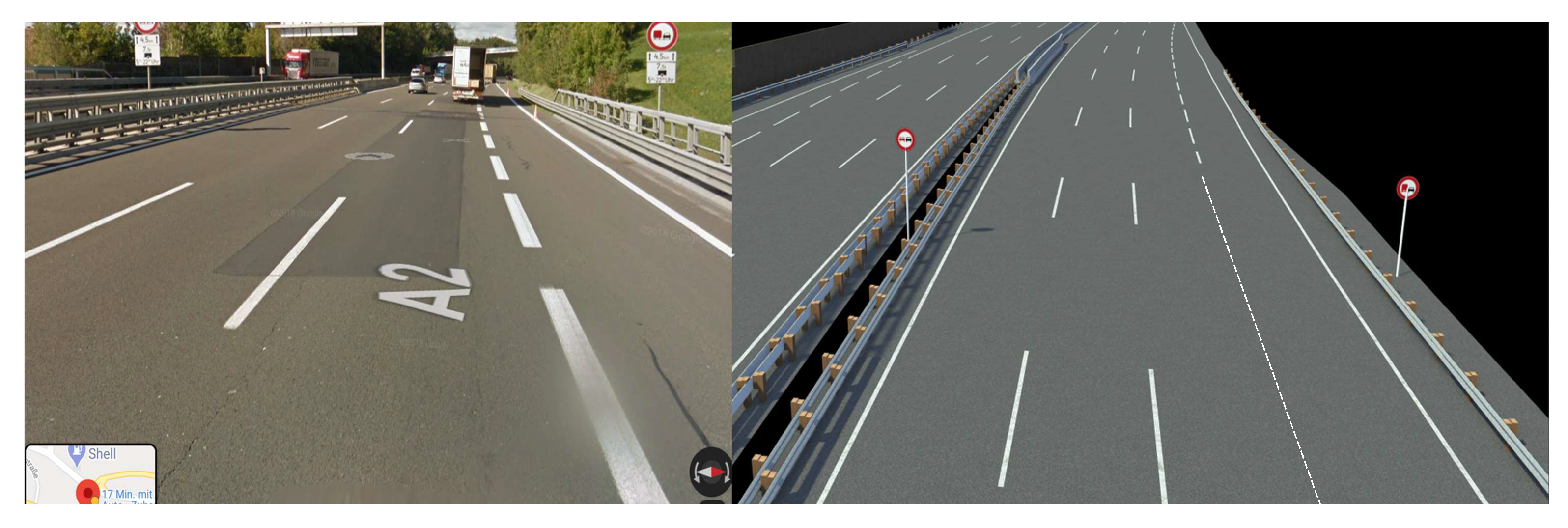
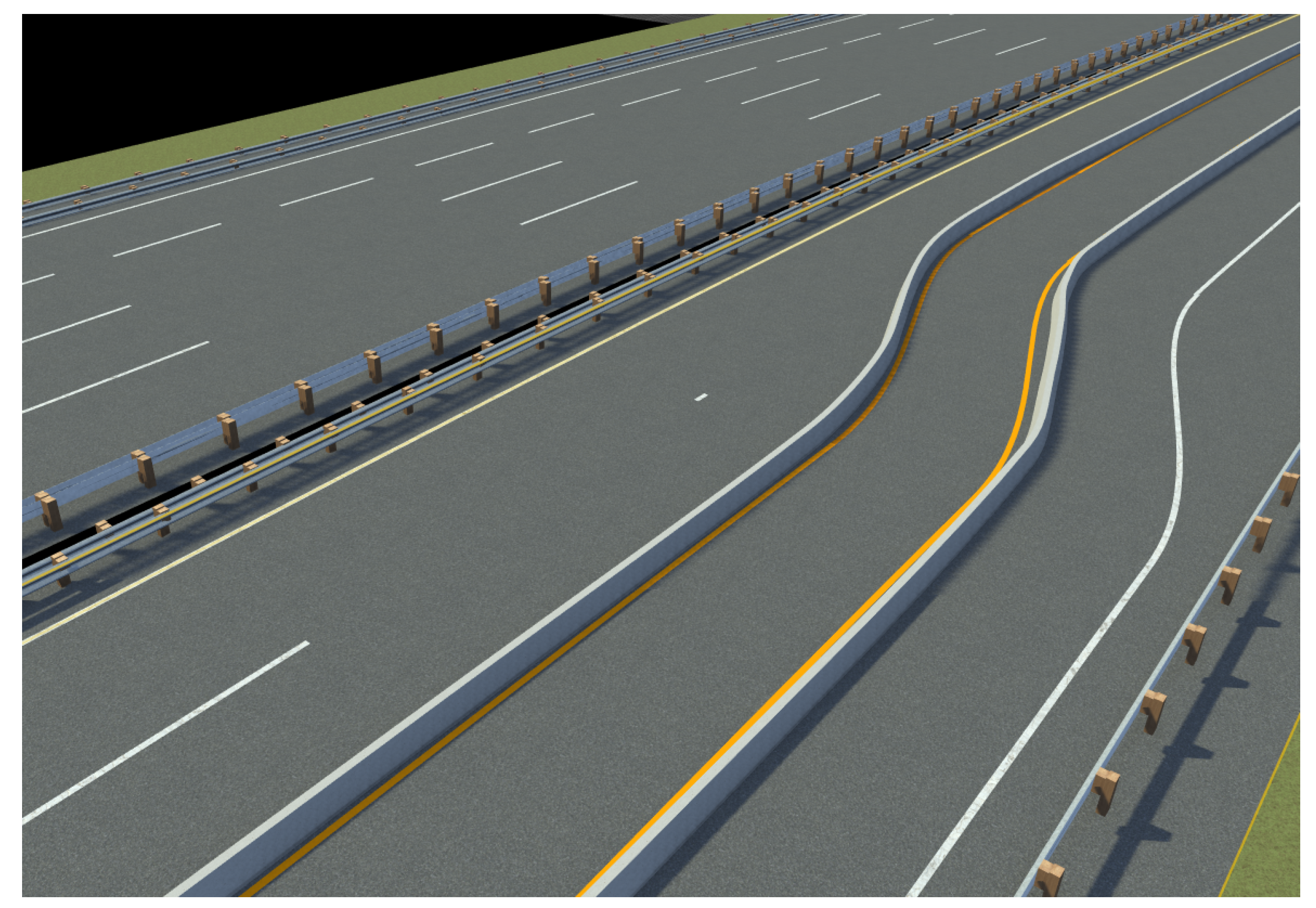
| Environment simulation: | A2 motorway as virtual environment | Modified A2 motorway with added contruction zone |
| Vehicle dynamics: | Python-based single track model | IPG CarMaker |
| Subsystem | Parameter | Value | Unit |
|---|---|---|---|
| Co-simulation: | Coupling step size | 0.02 | s |
| Test case | Coupling algorithm | ZOH | - |
| Vehicle dynamics step size | 0.02 | s | |
| Environment model step size | 0.02 | s | |
| Sensor model step size | 0.02 | s | |
| AD function step size | 0.02 | s | |
| Execution order | Sequential | - | |
| Scenario description | adapted from [71] | - | |
| Sensor models | Number of sensors | 2 | # |
| Type of sensor: | Sensor orientation | front-facing | - |
| Low-fidelity | Sensor range | 55 | m |
| object sensor | Sensor vertical FOV | 25 | deg |
| Sensor horizontal FOV | 60 | deg | |
| Type of sensor: | Sensor orientation | front-facing | - |
| Lane marking | Sensor range | 30 | m |
| sensor | Sensor horizontal FOV | 78 | deg |
| Vehicle | Software | IPG CarMaker | - |
| dynamics | Version | 8 | - |
| Vehicle specification (standard vehicle) | Tesla Model S | - | |
| AD function: | Target velocity (standard ODD) | 16 | m/s |
| ALKS parameter | Target velocity (extended ODD) | 19 | m/s |
| Framework Layer | Parameters | Formats | Description | Unit |
|---|---|---|---|---|
| Co-simulation | Coupling step size | Co-simulation setting specification format (e.g., XML) | Step size between simulation tools/models | s |
| Simulation tool/model step size | Time between calculation step of individual tool/model | s | ||
| Execution order | Order in which the individual models are calculated | # | ||
| Extrapolation method | Used method for extrapolation (e.g., ZOH) | - | ||
| Tool-specific co-simulation capability | Physical interface | ASAM OSI® | Defines the exchanged signals between tools/models | - |
| Simulation tools | Parameters for first 5 layers of the 6 layer model [11] | ASAM OpenSCENARIO® | Scenario description | - |
| Parameters describing the road network | ASAM OpenDRIVE® | Road network description | - | |
| Parameters describing the road surface | ASAM OpenCRG® | Road surface description | - | |
| Simulation models | Model specific parametrisation | Various | Necessary parameters to define the respective models | - |
Publisher’s Note: MDPI stays neutral with regard to jurisdictional claims in published maps and institutional affiliations. |
© 2021 by the authors. Licensee MDPI, Basel, Switzerland. This article is an open access article distributed under the terms and conditions of the Creative Commons Attribution (CC BY) license (https://creativecommons.org/licenses/by/4.0/).
Share and Cite
Weissensteiner, P.; Stettinger, G.; Rumetshofer, J.; Watzenig, D. Virtual Validation of an Automated Lane-Keeping System with an Extended Operational Design Domain. Electronics 2022, 11, 72. https://doi.org/10.3390/electronics11010072
Weissensteiner P, Stettinger G, Rumetshofer J, Watzenig D. Virtual Validation of an Automated Lane-Keeping System with an Extended Operational Design Domain. Electronics. 2022; 11(1):72. https://doi.org/10.3390/electronics11010072
Chicago/Turabian StyleWeissensteiner, Patrick, Georg Stettinger, Johannes Rumetshofer, and Daniel Watzenig. 2022. "Virtual Validation of an Automated Lane-Keeping System with an Extended Operational Design Domain" Electronics 11, no. 1: 72. https://doi.org/10.3390/electronics11010072
APA StyleWeissensteiner, P., Stettinger, G., Rumetshofer, J., & Watzenig, D. (2022). Virtual Validation of an Automated Lane-Keeping System with an Extended Operational Design Domain. Electronics, 11(1), 72. https://doi.org/10.3390/electronics11010072