Article

Design Space Exploration on High-Order QAM Demodulation Circuits: Algorithms, Arithmetic and Approximation Techniques †

School of Electrical and Computer Engineering, National Technical University of Athens, 15780 Athens, Greece
*
Author to whom correspondence should be addressed.
This paper is an extended version of our paper published in 10th International Conference Modern Circuit and Systems Technologies (MOCAST ), Thessaloniki, Greece, 5–7 July 2021.
Electronics 2022, 11(1), 39; https://doi.org/10.3390/electronics11010039
Submission received: 10 October 2021 / Revised: 14 December 2021 / Accepted: 20 December 2021 / Published: 23 December 2021

Abstract

:
Every new generation of wireless communication standard aims to improve the overall performance and quality of service (QoS), compared to the previous generations. Increased data rates, numbers and capabilities of connected devices, new applications, and higher data volume transfers are some of the key parameters that are of interest. To satisfy these increased requirements, the synergy between wireless technologies and optical transport will dominate the 5G network topologies. This work focuses on a fundamental digital function in an orthogonal frequency-division multiplexing (OFDM) baseband transceiver architecture and aims at improving the throughput and circuit complexity of this function. Specifically, we consider the high-order QAM demodulation and apply approximation techniques to achieve our goals. We adopt approximate computing as a design strategy to exploit the error resiliency of the QAM function and deliver significant gains in terms of critical performance metrics. Particularly, we take into consideration and explore four demodulation algorithms and develop accurate floating- and fixed-point circuits in VHDL. In addition, we further explore the effects of introducing approximate arithmetic components. For our test case, we consider 64-QAM demodulators, and the results suggest that the most promising design provides bit error rates (BER) ranging from 10 1 to 10 4 for SNR 0–14 dB in terms of accuracy. Targeting a Xilinx Zynq Ultrascale+ ZCU106 (XCZU7EV) FPGA device, the approximate circuits achieve up to 98 % reduction in LUT utilization, compared to the accurate floating-point model of the same algorithm, and up to a 122 % increase in operating frequency. In terms of power consumption, our most efficient circuit configurations consume 0.6–1.1 W when operating at their maximum clock frequency. Our results show that if the objective is to achieve high accuracy in terms of BER, the prevailing solution is the approximate LLR algorithm configured with fixed-point arithmetic and 8-bit truncation, providing 81 % decrease in LUTs and 13 % increase in frequency and sustains a throughput of 323 Msamples/s.

1. Introduction

Advanced technologies are utilized on every generation of mobile communication to provide improved network performance and consistent connectivity. Moreover, new and/or emerging applications, e.g., video streaming and augmented reality, promise to take advantage of these technologies to offer better and more consistent services to end users. However, the rapid development of these applications introduces strict bandwidth constraints to maintain robust quality of service (QoS). In this context, the fifth generation (5G) technology standard promises high bandwidth and ultra-low latency for data transmission [1]. To tackle these strict constraints imposed on networks infrastructures, efficient solutions must be provided. One part of the network that handles large volumes of data is the baseband unit (BBU), which is responsible for modulating/demodulating the transmitting/receiving data; in order to meet these demands, processors such as application-specific integrated circuits (ASICs) and field-programmable gate arrays (FPGAs) [2,3,4] are considered for implementing components of the 5G infrastructure. On one hand, when the objective is to offer high computational efficiency, then ASICs are preferred; on the other hand, FPGAs are able to provide attractive throughput/power ratio in addition to their adaptability to new functionalities. In either case, for the research community, providing optimal circuits for the main computationally intensive tasks of a digital communication system is of high importance.
The work presented in this paper focuses on a baseband unit implementation, and specifically introduces efficient QAM demodulation architectures. Our aim is to expand the design space by exploring solutions generic enough for diverse scenarios (e.g., varying conditions in the channel) by examining various QAM decoding and approximation techniques. Thus, we employ soft- and hard-decision algorithms relying on the calculation of the log likelihood ratio (LLR) and the maximum likelihood (ML), respectively, and apply approximation techniques on both floating-point and fixed-point arithmetic. In summary, our contributions are as follows:
  • The analysis and assessment of the effects of tunable approximation methods on high-order QAM demodulation, achieving improved hardware efficiency with limited accuracy loss, which is the first one performed in the literature to the best of our knowledge.
  • The assessment of various trade-offs (i.e., accuracy–hardware, accuracy–throughput, and accuracy–power) among different demodulation algorithms.
To achieve our goals, we employ VHDL coding to implement four demodulation algorithms and then apply circuit approximation techniques. The circuits are customized and validated on an FPGA device, but we refrain from utilizing dedicated high performance FPGA resources (i.e., DSP blocks, and RAM blocks) so as to be able to target also an ASIC implementation if needed. We focus on the most demanding part of their computation, i.e., the floating-point addition and the multiplication, and decrease the circuit complexity of the respective arithmetic units. More specifically, we develop approximate floating-point adders, generic hardware-friendly multipliers based on approximate high-radix encoding and bit truncations. To verify our approximate QAM demodulation circuits, we also model them in MATLAB to examine the effects of approximations and tune the circuits. To summarize, the QAM demodulators are designed to perform their computations in parallel and in a pipelined fashion. We also carry out extensive design space exploration (DSE) in terms of algorithm, arithmetic, and approximation levels to determine the most suitable configuration. According to our experimental results on Zynq Ultrascale+ ZCU106 (XCZU7EV) FPGA, via careful and methodical arithmetic approximations, the 64-QAM demodulation shows that the bit error rate (BER) lies between 10 1 and 10 4 for signal-to-noise ratio (SNR) 0–14 dB in all our implementations. For these BER values, our QAM designs deliver up to 98 % reduction in LUT utilization of the FPGA and up to 122 % increase in operating frequency compared to the respective accurate floating-point implementations.
The structure of the paper is as follows: Section 2 briefly presents related works regarding our target application and approximate circuit design. In Section 3, we present the circuits design from the algorithmic level down to the implementation level. Next, in Section 4, the results of the evaluated circuits are given. Finally, Section 5 concludes this paper.

2. Related Work

2.1. Telecommunication Functions on FPGAs

Communication standards/protocols change with fast pace, and as they evolve, new requirements arise that need to be integrated in the network infrastructure. One of the key components of a network infrastructure is the baseband processing unit (BBU). The functionality of a BBU is to implement the low-level DSP function required for transmission at the physical layer (L1).
The role of the BBU is often undertaken by an FPGA device, due to its adaptability to new functionalities and/or features. There are a lot of works in the literature that present OFDM-based telecommunication functions implemented on FPGAs. In [5], an FPGA-based OFDM transceiver that can support multiple IEEE 802.xx standards is presented. Dynamic partial reconfiguration is used in [6] to adapt the processing datapath of a non-continuous OFDM FPGA-based baseband architecture, while, based on the same principle in [7], an adaptable FFT core is given. Ref. [8] presents an SFO compensation method for OFDM. Finally, Ref. [9] presents the experimental results of transmitting/receiving an OFDM 5G NR signal using a real-time FPGA processing pipeline. All of these works consider a complete OFDM processing pipeline and/or target processing blocks that are more computationally demanding (e.g., FFT/IFFT, and SFO) while not considering any optimizations other than computation scheduling, parallel hardware architecture design and/or pipeline.

2.2. Circuit Approximation Techniques

In the field of approximate circuit design, approximation methods are applied at component level, e.g., adders and multipliers [10,11,12,13,14,15,16,17,18,19], as well as to bigger accelerators [20,21,22,23]. Most of these works focus on logic simplification techniques, namely, aim at reducing the circuit complexity of the designs by pruning circuit nodes or using inexact building blocks. In addition to logic simplification, other state-of-the-art approaches involve voltage over-scaling [24] and over-clocking [25].
Regarding approximate adders and multipliers, which are also the main focus of our work, the EvoApprox8b library [12] provides numerous inexact designs of different accuracy and hardware efficiency. It is also worth mentioning that the integer arithmetic circuits [10,11,13,14,15,17,18] have received more research attention than their floating-point counterparts [16,19]. Another significant feature of several state-of-the-art works is the runtime accuracy/approximation configurability. In this context, the designs of [15,16] drive the operand bits to AND gates to tune the approximation strength by providing either the actual bit or ‘0’ to the input of the multiplier. To provide dynamic configurability to adders, the designs of [17,18] share the addition into several sub-adders.
Regarding approximate accelerators, the main target is the implementation of kernels from the digital signal processing (DSP) and artificial intelligence (AI) domains. In [20], a methodology for delivering approximate DSP and AI accelerators is proposed, involving design space exploration on algorithms, arithmetic, and approximate components. The authors of [21] propose an approximation framework that integrates approximate multipliers in deep neural networks. Similarly, in [23], the authors develop convolutional neural network architectures with various approximate fixed- and floating-point arithmetic.

3. Design of Approximate QAM Demodulation Circuits

To accommodate design space exploration, we design parallel M-QAM demodulation architectures in a modular approach. In this way, we are able to adopt alternative arithmetic and/or replace the arithmetic units with approximate ones.
We consider M-QAM keying signals (amplitude+phase) and their corresponding gray-coded constellation map, where each constellation point is represented by a vector b of N = log 2 M bits. Assuming that s is the transmitted symbol, each symbol is expressed as z = s · G c h + w 0 , where G c h is the channel frequency response and w 0 is the additive white Gaussian noise (AWGN) of variance σ 0 2 . By performing zero-forcing frequency equalization and phase correction, the received symbol is equal to r = s + w , where w is the AWGN of variance σ 2 = σ 0 2 / | G c h | 2 .
Subsequently, we present the QAM demodulation algorithms, their high-level block architecture, and implementation details regarding their basic components and the applied approximations.

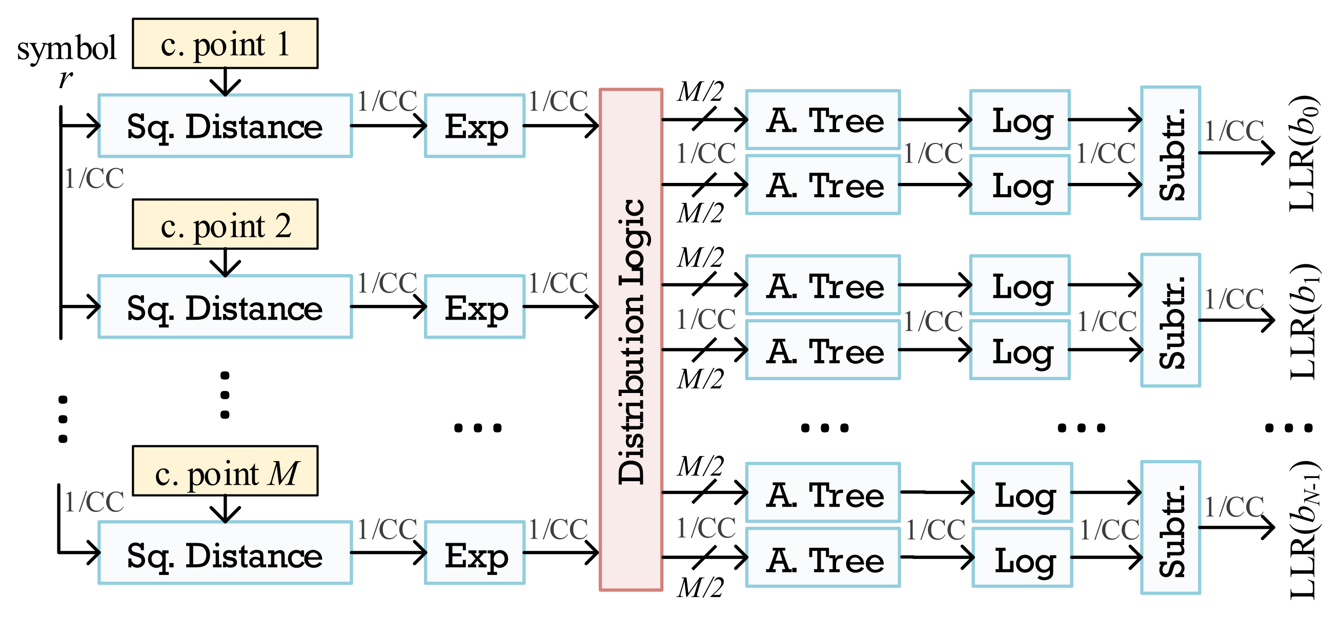
3.1. Exact LLR Architecture

The exact LLR (ELLR) method predicts each bit of the received symbol based on probabilities. Assuming equal probabilities P ( b i = 0 ) = P ( b i = 1 ) = 1 / 2 , the LLR for the i-th bit of the symbol is defined as [26]
L L R ( b i ) = ln s : b i = 0 e 1 σ 2 ( ( r x s x ) 2 + ( r y s y ) 2 ) s : b i = 1 e 1 σ 2 ( ( r x s x ) 2 + ( r y s y ) 2 )
where ( r x , r y ) are the in-phase and quadrature coordinates of the received symbol r, and ( s x , s y ) are the coordinates of the constellation points s with 0 and 1 in the i-th bit.
In Figure 1, we present our ELLR architecture. As shown, all the LLRs are calculated in parallel, with the modules retaining the input throughput of 1 data per clock cycle (CC). Our distribution logic module forwards the square distances for the 0 and 1 constellation points in the corresponding adder tree to perform the accumulations of Equation (1). The ELLR method requires the implementation of exponential and natural logarithmic functions; thus, we adopt two different approaches in VHDL, i.e., the hyperbolic coordinate rotation digital computer (CORDIC) function and a polynomial approximate function based on the Remez algorithm [27]. CORDIC is designed in a generic way and is able to function with a configurable bit-width at compile time by the user in order to explore different resource–accuracy trade-offs. As for the polynomial function, we examine various polynomial degrees and evaluate their impact on resources and accuracy. Both functions are designed to be synchronous and fully pipelined, and impose only a small latency, e.g., for 64-QAM, the latency is 43 CCs and 14 CCs for the CORDIC and polynomial functions, respectively.

3.2. Approximate LLR Architecture

To avoid the exponent and logarithmic calculations as well as the additions [26], Equation (1) can be simplified by using only the nearest constellation point with b i = 0 and the nearest constellation point with b i = 1 . The final result is obtained by subtracting the minimum distances. This algorithmic approximation is called approximate LLR (ALLR) and is given by (2):
L L R ( b i ) = 1 σ 2 min s : b i = 0 { ( r x s x ) 2 + ( r y s y ) 2 ) } min s : b i = 1 { ( r x s x ) 2 + ( r y s y ) 2 ) }
Figure 2 presents the ALLR architecture. The ALLR architecture is fully pipelined and operates on a continuous stream of data without stalling the processing. The minimum of the M / 2 distances is computed by a fully pipelined comparator tree that is able to perform the comparison for every two inputs in log 2 M / 2 steps. The minimum value is stored in a register, to be used by the output subtractor. For 64-QAM, the latency is 4 CCs, while for the 256-QAM, two additional clock cycles are required. The extra clock cycles in the 256-QAM are added due to the need of a bigger tree to calculate the minimum distances.

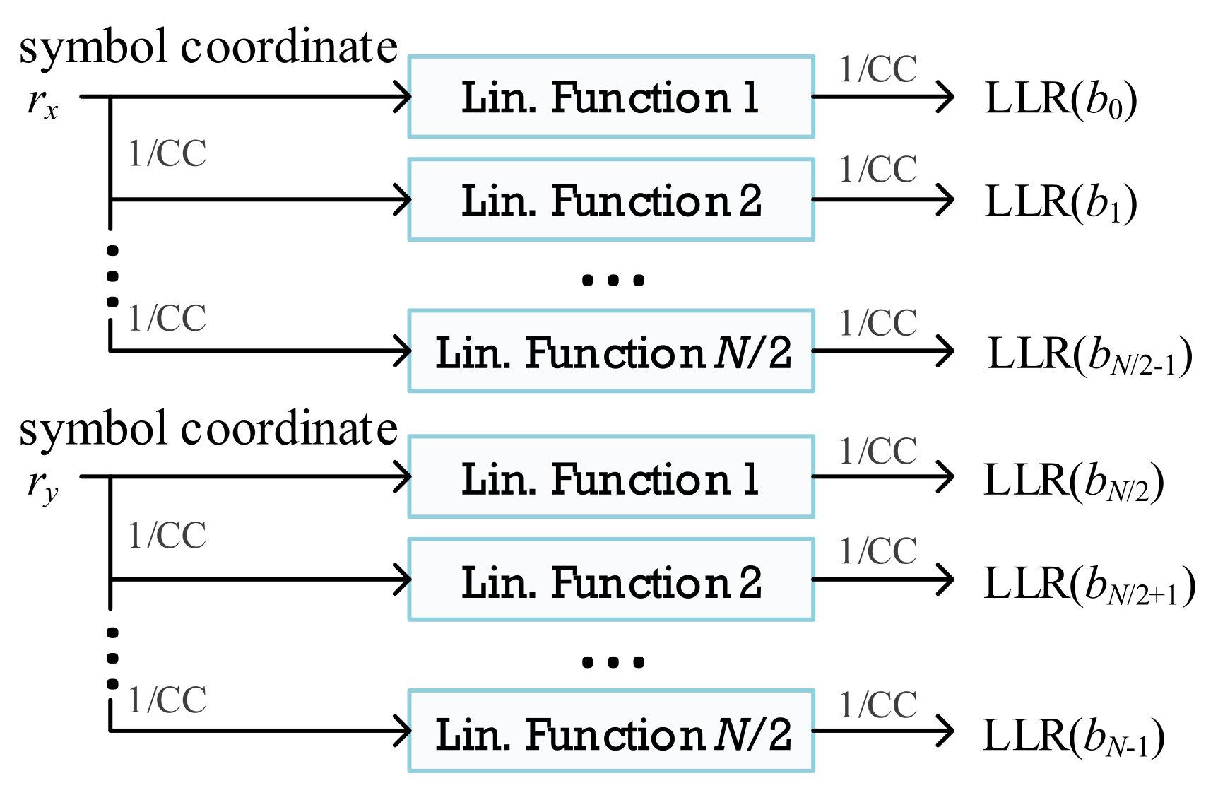
3.3. Piecewise LLR Architecture

The piecewise LLR (PLLR) algorithm approximates Equation (1) by using a linear function [28]. This method considers k = 1 , 2 , , N , as well as d x , k and d y , k , which denote the half distance between the partitions boundaries of b x , k and b y , k , respectively. Given that r is the received symbol with coordinates ( r x , r y ), the LLR is calculated as
L L R ( b x / y , k ) = | G c h | 2 · D x / y , k , where D x / y , k = r x / y k = 1 | D x / y , k 1 | + d x / y , k k > 1
Our PLLR architecture is presented in Figure 3, where N linear functions are calculated in parallel. The computation of D x / y , k involves only additions, followed by a multiplication with | G c h | 2 , and thus, the circuit complexity is significantly decreased compared to the previous demodulation methods. Similarly to ALLR, our PLLR design is fully pipelined, and performs the computations of the linear functions in streaming mode. The latency is 2 CCs and 3 CCs for the 64-QAM and 256-QAM, respectively (256-QAM requires extra additions).

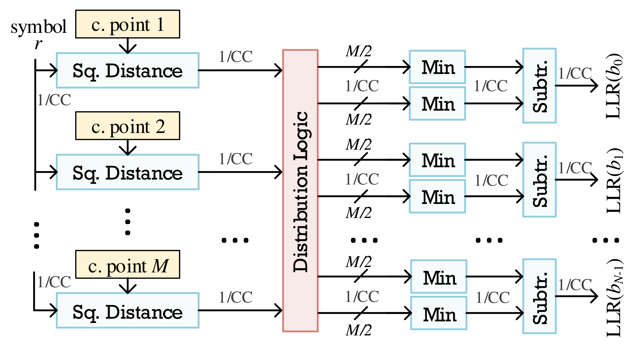
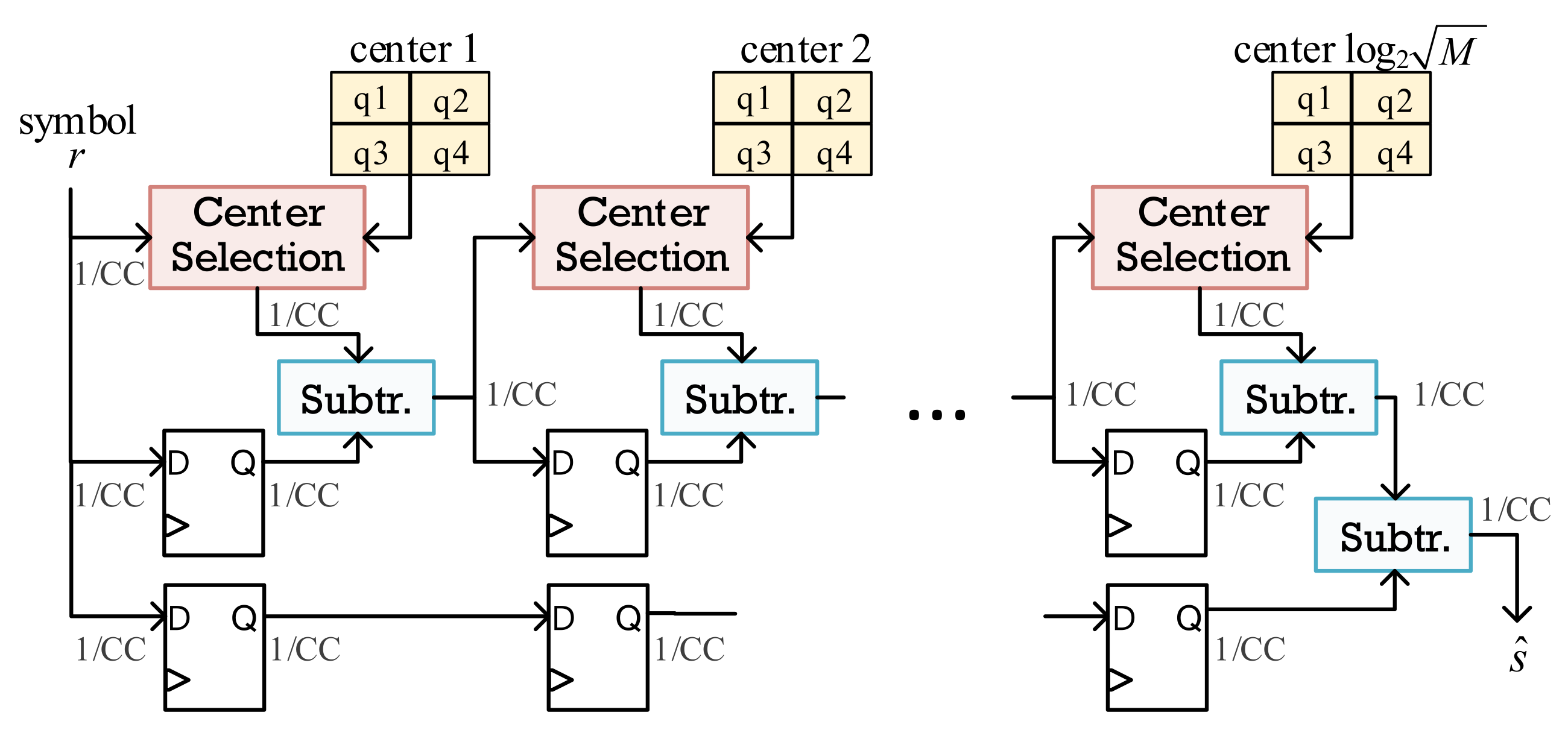
3.4. Approximate ML Architecture

Typical ML methods use non-linear functions to calculate the demodulation symbol. To decrease the conventional complexity, the approximate ML (AML) method of [29] uses a closed function of the estimated channel and received signal to estimate the QAM symbol:
s ^ = p = 1 log 2 M c p , where c p = 3 M M 1 2 p e j g ( r m = 1 p 1 c m )
The proposed AML architecture is presented in Figure 4. Our design pre-calculates and stores in ROMs the log 2 M centers c p . Initially, the first center is identified by the quarter in which the input is located. Subsequently, each center is identified by the quarter that is derived when all the previous centers are subtracted from the input. With this approach, we avoid storing all the intermediate centers to accumulate them as indicated by Equation (4). In contrast, the accumulation is performed as s ^ = r ( r c 1 c 2 c log 2 M ) = c 1 + c 2 + + c log 2 M . The AML architecture has a log 2 M +1 CCs latency, i.e., 4 CCs and 5 CCs for 64-QAM and 256-QAM, respectively.

3.5. Arithmetic Approximation Techniques

We adopt both the floating-point (FLP) and fixed-point (FXP) arithmetic formats in our QAM demodulation circuits, and perform approximate arithmetic operations. Next, we describe the approximate arithmetic units used in our QAM designs.

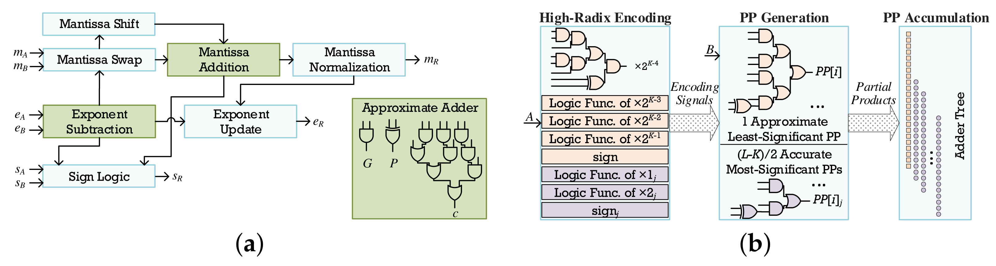
3.5.1. Floating-Point Approximations

Both the mantissa adder and exponent subtractor are replaced with an approximate carry look-ahead adder [19] that decreases the circuit complexity of the floating-point (FLP) addition. By splitting the calculations in two segments and omitting the least-significant one, an approximation is inserted in the generation of the carry output of the i-th stage. As a result, the calculation is performed approximately in a window of size W.
c ( i + 1 ) = j = i W + 1 i G j m = j + 1 i 1 P m
where P i = A i B i and G i = A i · B i are the propagate and generate signals of the i-th stage, respectively.
Figure 5a presents the high-level architecture of the approximate FLP adder, where the inexact mantissa addition and exponent subtraction are highlighted. The rest of the components remain the same as in the accurate FLP addition, except that we do not apply any rounding technique in the mantissa sum. In the right-hand side (Figure 5a), we present the basic logic block of the approximate carry look-ahead adder, which approximately calculates the carries according to Equation (5) and stores them in DFFs. The total latency of the approximate FLP adder is 5 CCs.

3.5.2. Fixed-Point Approximations

In this work, we target multiplication architectures based on radix encodings, due to their efficiency compared to other algorithms [30]. To decrease the circuit complexity of the fixed-point (FXP) multiplication, we perform inexact partial product (PP) generation based on the hybrid high-radix encoding [14]. This technique tunes the approximation levels with the configuration parameter K = 2 · l 4 . In particular, the L K MSBs of one of the L-bit input operands (e.g., A) are accurately encoded with radix-4, while its K LSBs are approximately encoded with radix- 2 K . The approximation is inserted by mapping the high-radix encoded values to the nearest of the four largest powers of 2 or 0 [14]:
A = a L 1 a 1 a 0 A = A M S B + A L S B = j = K / 2 K 4 L / 2 1 y j R 4 4 j + y 0 R 2 K
where
y j R 4 = 2 a 2 j + 1 + a 2 j + a 2 j 1 y j R 4 { 0 , ± 1 , ± 2 }
y 0 R 2 K = 2 K 1 a K 1 + 2 K 2 a K 2 + + a 0 y 0 R 2 K { 0 , ± 1 , , ± ( 2 K 1 1 ) , 2 K 1 }
To decrease the circuit complexity of the y 0 R 2 K encoding, which is due to values that are not a power of 2, all these values along with the K–4 smallest powers of 2 are mapped to the nearest of the four largest powers of 2 or 0, as shown in the approximate encoding table of [14]. As a result, the approximate version of the high-radix encoding uses y ^ 0 R 2 K { 0 , ± 2 K 4 , ± 2 K 3 , ± 2 K 2 , ± 2 K 1 } instead of y 0 R 2 K , and the encoding circuit is similar to the classical y j R 4 encoder.
The approximate multiplier (Figure 5b) generates (LK)/2 accurate PPs based on the radix-4 encoding, i.e., y j R 4 , and 1 approximate PP based on the radix- 2 K encoding, i.e., y ^ 0 R 2 K , which practically substitutes the K / 2 least-significant PPs of the accurate radix-4 multiplier. We implement such multipliers for various K values, following the architecture illustrated in Figure 5b. The first stage is the approximate hybrid high-radix encoding, which involves circuits, such as the one implementing × 2 K 4 , i.e., one of the five 1-bit signals that approximately encode the LSB segment of A. Similar small circuits are implemented for the accurate classical encoding of the MSB segment. Next, we forward all the encoding signals along with B in the PP generation module, and finally, we accumulate the PPs in an accurate adder tree. We note that the units for both encodings and i-th bit PP generators are fixed and independent of K. The configuration parameter affects only the bit-width of the approximate PP and the number of accurate PPs, and thus, the number of 1-bit approximate PP generators and accurate encoders and PP generators, respectively. The total latency of our multiplication circuit is 5 CCs.

4. Experimental Evaluation

4.1. Experimental Setup

In this section, we present the experimental results for our QAM demodulation architectures in terms of accuracy, hardware resources and power consumption. We examine various arithmetic and approximation configurations, and we discuss the most interesting results from our design space exploration. For the evaluation, we assume a transmitter producing random bits and a convolutional encoder of 1 / 2 code rate with generator polynomial ( 133 , 171 ) and constraint length of 7. The QAM modulator considers a normalized constellation diagram, and the modulated signal is transmitted through an AWGN channel of variance σ 2 = 10 ( SNR d B / 10 ) . Finally, the outputs of our LLR-based demodulation architectures are processed by a Viterbi decoder in unquantized mode.
To evaluate the hardware efficiency of the proposed approximate designs, we implement our QAM architectures on the Xilinx Zynq Ultrascale+ ZCU106 (XCZU7EV) FPGA, using parametric VHDL and design space exploration. Considering that the proposed architectures can be deployed on various technologies, e.g., ASICs, flash FPGAs, we assess the circuits’ complexity and throughput without employing elaborate FPGA primitives, such as the DSPs. Hence, in a prototyping fashion, we force the Xilinx Vivado 2019.2 tool to utilize only LUTs and DFFs. Moreover, for the designs without approximate arithmetic units, i.e., the accurate FLP and FXP designs as well as the FXP designs with bit truncation, we force the tool to employ the built-in libraries to map the arithmetic operations on the LUTs. The data bit-width of the FLP designs is 32 bits, while the bit-width of the accurate FXP design is 16 bits (with 14 fractional bits). Moreover, we present the power consumption, as reported by Vivado Design Suite, for the maximum achievable frequency. To assess the accuracy of our approximate demodulation designs, we use two metrics: (i) BER, which is equal to the number of bit errors divided by the total number of transmitted bits, and (ii) mean relative error (MRE), i.e., the mean error of LLRs and symbol distances for the LLR and ML techniques, respectively (versus the “accurate” floating-point model).
We note that we do not present results for the ELLR, as it provides similar accuracy to ALLR, at the expense of increased resource utilization. For example, for 64-QAM, the BER scaling of ELLR almost matches the scaling of ALLR (for small SNR, it is the same). In terms of hardware, when considering the accurate FXP arithmetic, the CORDIC-based implementation utilizes 2.2 × LUTs and 3.8 × DFFs, while the polynomial-based implementation utilizes 2.6 × LUTs and 8 × DFFs. The resource utilization is increased for higher-order QAMs, e.g., for 256-QAM, the ELLR does not fit in such a big FPGA device, even when using approximation techniques.

4.2. Exploration Results

Figure 6 illustrates the BER scaling of our 64-QAM architectures for different SNR values per QAM symbol transmitted. The ALLR algorithm (Figure 6a) with a fixed-point arithmetic in conjunction with approximations provides similar BER performance to the reference FLP implementation. Specifically, the accurate FXP and approximate FXP-T8 and FXP-K6 designs show maximum 1 % relative error in BER values compared to FLP. On the other hand, FXP-T11 shows increased relative errors (1%–150%) as SNR increases (0–14 dB); however, these BER values are still small. As for the FLP-W4 implementation, its performance is the worst for all SNR values; thus, it is non-viable for deployment in real-world scenarios. The results suggest that when using relative small FXP approximations, the computation error that propagates through the circuit is mitigated, and the final LLR values are closer to the reference accurate FLP. However, this is not the case for the approximate FLP-W4 and FXP-T11 circuits.
PLLR (Figure 6b) presents the same BER performance as ALLR, with BER values ranging from 10 1 to 10 4 . The accurate FXP and approximate FXP-T8 implementations follow closely the BER curve of the reference accurate FLP implementation, and show ∼ 0.5 % to ∼ 14 % relative error in BER values as SNR increases. The performance of FXP-T11 declines significantly compared to the ALLR counterpart, and exhibits ∼ 2 % to ∼ 630 % relative error in BER values for increased SNR compared to the FLP implementation. For the FLP-W4 implementation of PLLR, we note that it performs much better than the FLP-W4 of ALLR, but still not quite enough to be considered for actual deployment on a system. Again, taking into account the approximation used and the operation performed, the approximate FXP circuits seem to be more robust.
The AML algorithm (Figure 6c) is orders of magnitude worse than the ALLR and PLLR algorithms for the same input dataset and SNR range (BER of 10 1 to 10 2 ), regardless of the arithmetic and approximation used. Considering only the specific algorithm and its implementations, the FXP and FXP-T8 designs demonstrate the same BER performance as the reference FLP implementation with relative error in BER values near 0 % for FXP and no more than 3 % for FXP-T8 for all SNR values. On the other hand, FXP-T11 is inefficient; thus, aggressive approximations based on truncation seem unreasonable for AML. As for the FLP-W4 variant, it follows the same trend as the reference FLP, but presents 0 % to 135 % relative error in BER values as the SNR increases. In this algorithm, any significant error that appears in one stage will lead the comparison performed to select wrong reference centers, and as a result, larger errors will be introduced in the next stage, leading to increased accumulated error and, thus, very inefficient performance.
In Table 1, we present the implementation (place and route) results of our 64-QAM circuits on ZCU106. The table also reports the average MRE of LLR values for SNR 0–14 dB. As shown, ALLR is the more demanding one in terms of resource utilization for all arithmetic and approximations used. Comparing only the reference FLP implementations for each algorithm, we observe a significant difference in LUT/DFF utilization. Specifically, PLLR and AML have ∼98% less resource utilization than ALLR, while also achieving higher operating frequency of 16 % and 35 % , respectively. When also considering the BER scaling, PLLR is the most efficient demodulator for floating-point arithmetic. Next, we examine the gains in resource utilization and operating frequency for each employed demodulation algorithm:
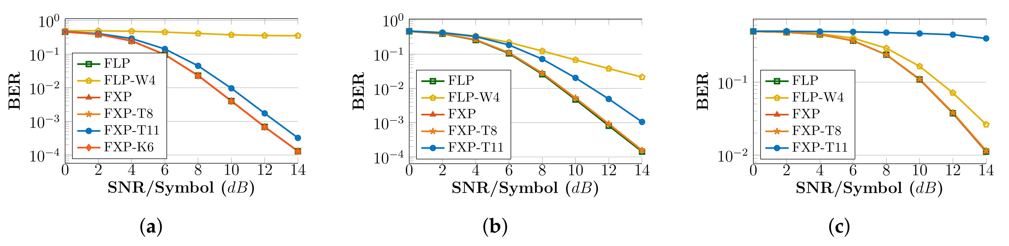
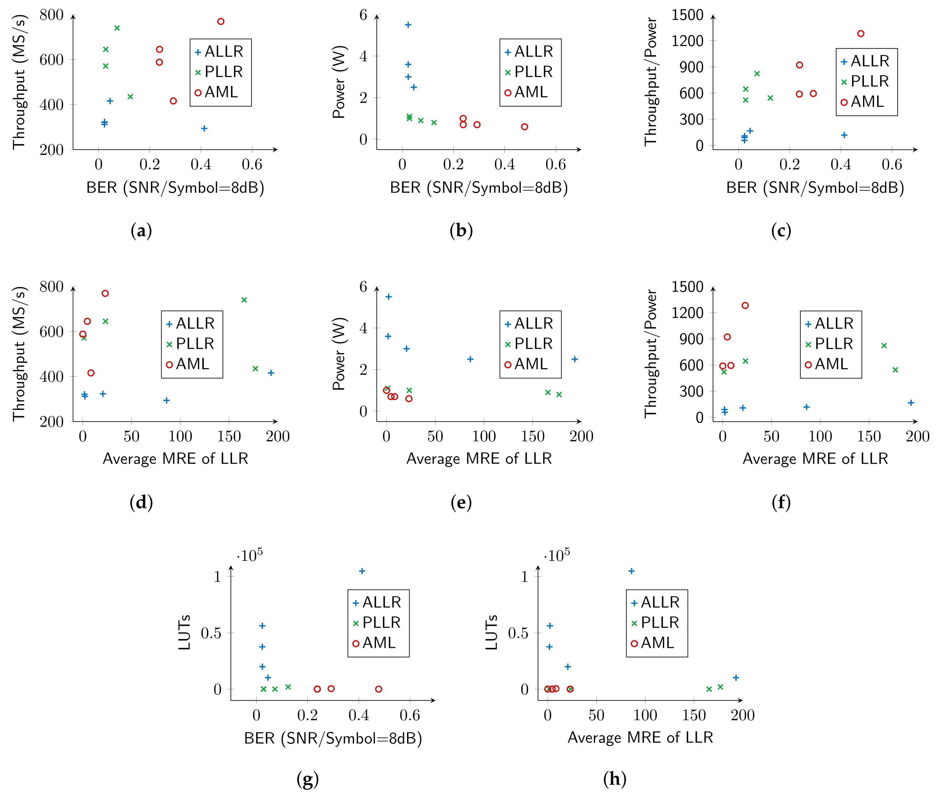
  • ALLR circuits: The FLP-W4 implementation provides a negligible reduction of only 1 % in LUTs and only 3 % increase in frequency compared to FLP. On the other hand, the fixed-point ALLR circuits deliver increased gains. The accurate FXP circuit gains 50 % in resources and has 9 % higher frequency, while FXP-T8 and FXP-T11 have 81 % and 90 % reduction in LUTS, 75 % and 78 % reduction in DFFs, and 13 % and 45 % increase in frequency, respectively. FXP-K6 reduces its utilization by 64 % in LUTs, 21 % in DFFs and operates 12 % faster. If we seek BER performance in-line with FLP, circuits with moderate truncation (FXP-T8) or approximate multipliers (FXP-K6) can be used. Additionally, considering the MRE metric, FXP-T8 is worse than FXP-K6 ( 20.59 vs 1.74 ).
  • PLLR circuits: FLP-W4 offers only 2 % reduction in LUTs, but gains 30 % in frequency compared to the FLP circuit. Regarding fixed-point circuits, we observe 92 % , 96 % , 97 % reduction in LUTs, 75 % , 85 % , 89 % reduction in DFFs and 71 % , 93 % , 122 % higher operating frequencies for the accurate FXP, approximate FXP-T8 and FXP-T11 circuits, respectively. As SNR increases (Figure 6b), the BER performance of FLP-W4 and FXP-T11 deviates significantly from FLP; thus, a fixed-point architecture with moderate truncation can be adopted.
  • AML circuits: FLP-W4 achieves 9 % LUT reduction and 8 % frequency increase compared with the accurate FLP circuit. For the fixed-point circuits, we observe 96 % LUT reduction, 98 % DFF reduction either we have accurate circuits (FXP) or approximate ones (FXP-T8, FXP-T11). Regarding frequency, an increase by 53 % for the accurate FXP, 68 % for the FXP-T8 and almost 100 % for the FXP-T11 is seen. However, we note that AML provides the worst BER performance among all algorithms and arithmetic, and thus, its deployment on a real-world system may be limited. Incorporating the BER results (Figure 6c), a fixed-point with moderate truncation (T8) circuit is preferable, as it follows the BER curve of FLP.
Considering the power consumption (Table 1) of the presented circuits, we observe that for each algorithm group, there is an increase in the power consumption of the accurate FXP implementation compared to the FLP implementations, either accurate or approximate. Moreover, the approximate FXP implementations consume less power than the accurate FXP, but in the same degree as the FLP ones. This behavior can be justified taking into account that the target platform for our evaluation is an FPGA device, which has static and dynamic power factors. For example, considering the PLLR implementations, a significant reduction in resource utilization is observed moving from the accurate FLP to FXP-T11, thus the static power of the circuit, which relates to the number of used resources, is reduced. However, the operating frequency increases, which leads to higher switching activity of the utilized resources and thus, the dynamic power consumption of the circuits also increases and “compensates” for the lower static power consumed. Additionally, another factor that we must take into account is that the synthesis tool, after placement and routing may spread the utilized resources of a circuit across the FPGA fabric leading to increase usage of routing resources that also consume power. That power consumption (static and dynamic) is also included in the one reported by the tool.
When considering higher-order QAMs, i.e., 256-QAM, as explained before, ELLR does not fit in the FPGA. Regarding ALLR, it is possible to fit only the FXP implementations, as the 256-QAM ALLR utilizes ∼4× the resources of the 64-QAM demodulator. As a result, the LUT utilization reaches 97 % of the total chip’s resources for the accurate FXP implementation with datapath of 16 bits. However, when inserting approximations it is significantly decreased: the designs with bit truncation i.e., FXP-T8 and FXP-T11, utilize 38 % and 21 % of the LUT resources, while the use of the approximate multiplier (FXP-K6) reduces the utilization to 62 % . Similar scaling is observed for the other two algorithms, which enable the implementation of even higher QAM orders, e.g., 1024, as they impose low computational complexity. Regarding the BER performance we have observed that the approximations introduced perform equally well for higher-order QAM modulation formats, e.g., 256-QAM. Finally, in real-world scenarios, the FPGA is used to implement additional computational-intensive functions of the baseband processing chain; thus, it is important not to preserve all the resources for the demodulation. In this direction, as shown, methodical approximations can provide significant resource gains at the expense of small accuracy loss. In addition, when considering more platform-specific implementations, e.g., to exploit the hardwired DSP primitives of the FPGA, we can achieve additional resource savings as well as increased throughput.

4.3. Pareto Trade-Off Analysis: Hardware Resources vs. Accuracy

Figure 7 shows a comparison of all the circuits considering different metric combinations in a Pareto diagram. Specifically, in Figure 7a–c,g, we consider the BER performance versus throughput, power, throughput/power ratio and LUT utilization for a fixed SNR value (8 dB). In these Figures, we do not observe much diversity regarding the circuits that form the Pareto fronts. Specifically, in all four diagrams the Pareto front consist of circuits from ALLR and PLLR algorithms. However, in Figure 7b,g there are also circuits from the AML algorithm that form the Pareto front. However, considering the best trade-off of the examined metrics, the diagrams show that the optimal circuits belong to the PLLR algorithm. Next, in Figure 7d–f,h, we consider the average MRE instead of BER performance, while keeping the other metrics the same. In these test cases, the Pareto front consist of circuits from all algorithms, but the PLLR algorithm has fewer circuits. The most optimal circuits that give the best trade-off of the metrics used are from the AML algorithm; however, one should be cautious when considering the specific algorithm for deployment because it provides the worst BER performance compared to the others for the same SNR values.
Solely in terms of resources and throughput, our exploration indicates that, regardless of algorithm, fixed-point architectures are the most efficient and truncation is the preferable approximation technique. Taking into account the BER results, the ALLR and PLLR algorithms have better BER performance than AML, with ALLR being slightly better than PLLR. So, we consider the most advantageous QAM demodulator circuit to be the ALLR FXP-T8 implementation.

5. Conclusions

In this paper, we implemented and evaluated multiple hardware QAM demodulation architectures by performing an extensive DSE in terms of demodulation algorithms, arithmetic, and approximation techniques. The examined algorithms involve soft- and hard- decision decodings of different complexity, whereas, regarding the approximation techniques, we employ approximation-configurable adders and multipliers on floating- and fixed-point arithmetic. Our experimental analysis shows that the proposed approximate 64-QAM demodulators provide BER ranging from 10 1 to 10 4 for SNR 0–14 dB, while they deliver significant resource gains in the Xilinx ZC106 FPGA. From the DSE and experimental results, we conclude the following: (i) The high-order QAM circuits for the Exact LLR algorithm demand an increased amount of resources, even when adopting fixed-point representation and approximation techniques, while its BER performance is matched by the approximate LLR algorithm. (ii) By introducing approximations in the datapath of the approximate LLR algorithm, we significantly reduce the circuit complexity in exchange for negligible accuracy loss, and thus, it can be implemented on the FPGA without utilizing all the resources. (iii) The piecewise LLR and approximate maximum likelihood algorithms utilize a limited amount of resources and deliver increased throughput; thus, very high-order QAMs are facilitated. However, the piecewise LLR provides slightly worse BER compared to approximate LLR algorithm, while the approximate maximum likelihood gives inefficient BER performance. (iv) A single QAM circuit solution that fits in all circumstances/systems cannot easily be obtained without considering additional constraints (e.g., accurate modeling of transmission channel, arithmetic errors from other DSP functions, and resources required for other digital functions).

Author Contributions

Conceptualization, V.L. and I.S.; investigation, G.A. and I.S.; methodology, D.S.; implementation, I.S. and G.A.; simulation, G.A.; validation, I.S. and G.A.; visualization, V.L. and I.S.; writing—original draft, I.S. and V.L.; writing—review and editing, G.L. and D.S.; supervision, G.L. and D.S. All authors have read and agreed to the published version of the manuscript.

Funding

The work was partially funded by the European Union’s Horizon 2020 research and innovation program, under project SDK4ED, grant agreement No. 780572.

Conflicts of Interest

The authors declare no conflict of interest.

References

  1. Andrews, J.G.; Buzzi, S.; Choi, W.; Hanly, S.V.; Lozano, A.; Soong, A.C.K.; Zhang, J.C. What Will 5G Be? IEEE J. Sel. Areas Commun. 2014, 32, 1065–1082. [Google Scholar] [CrossRef]
  2. Kuon, I.; Tessier, R.; Rose, J. FPGA Architecture: Survey and Challenges; Now Publishers: Hanover, MA, USA, 2008; pp. 135–253. [Google Scholar] [CrossRef]
  3. Lentaris, G.; Maragos, K.; Stratakos, I.; Papadopoulos, L.; Papanikolaou, O.; Soudris, D.; Lourakis, M.; Zabulis, X.; Gonzalez-Arjona, D.; Furano, G. High-performance embedded computing in space: Evaluation of platforms for vision-based navigation. J. Aerosp. Inf. Syst. 2018, 15, 178–192. [Google Scholar] [CrossRef]
  4. Leon, V.; Stamoulias, I.; Lentaris, G.; Soudris, D.; Gonzalez-Arjona, D.; Domingo, R.; Codinachs, D.M.; Conway, I. Development and Testing on the European Space-Grade BRAVE FPGAs: Evaluation of NG-Large Using High-Performance DSP Benchmarks. IEEE Access 2021, 9, 131877–131892. [Google Scholar] [CrossRef]
  5. Pham, T.H.; Fahmy, S.A.; McLoughlin, I.V. An End-to-End Multi-Standard OFDM Transceiver Architecture Using FPGA Partial Reconfiguration. IEEE Access 2017, 5, 21002–21015. [Google Scholar] [CrossRef]
  6. Ferreira, M.L.; Ferreira, J.C. Reconfigurable NC-OFDM processor for 5G communications. In Proceedings of the 2015 IEEE 13th International Conference on Embedded and Ubiquitous Computing, Porto, Portugal, 21–23 October 2015; pp. 199–204. [Google Scholar]
  7. Ferreira, M.L.; Barahimi, A.; Ferreira, J.C. Reconfigurable FPGA-based FFT processor for cognitive radio applications. In Proceedings of the International Symposium on Applied Reconfigurable Computing, Mangaratiba, Brazil, 22–24 March 2016; Springer: Berlin/Heidelberg, Germany, 2016; pp. 223–232. [Google Scholar]
  8. Deng, R.; He, J.; Chen, M.; Chen, L. SFO compensation by pilot-aided channel estimation for real-time DDO-OFDM system. Opt. Commun. 2015, 355, 172–176. [Google Scholar] [CrossRef]
  9. Rommel, S.; Grivas, E.; Cimoli, B.; Dodane, D.; Morales, A.; Pikasis, E.; Bourderionnet, J.; Feugnet, G.; Carvalho, J.B.; Katsikis, M.; et al. Real-time high-bandwidth mm-wave 5G NR signal transmission with analog radio-over-fiber fronthaul over multi-core fiber. Eurasip J. Wirel. Commun. Netw. 2021, 2021, 43. [Google Scholar] [CrossRef]
  10. Jiang, H.; Han, J.; Qiao, F.; Lombardi, F. Approximate Radix-8 Booth Multipliers for Low-Power and High-Performance Operation. IEEE Trans. Comput. 2016, 65, 2638–2644. [Google Scholar] [CrossRef]
  11. Liu, W.; Qian, L.; Wang, C.; Jiang, H.; Han, J.; Lombardi, F. Design of Approximate Radix-4 Booth Multipliers for Error-Tolerant Computing. IEEE Trans. Comput. 2017, 66, 1435–1441. [Google Scholar] [CrossRef]
  12. Mrazek, V.; Hrbacek, R.; Vasicek, Z.; Sekanina, L. EvoApprox8b: Library of Approximate Adders and Multipliers for Circuit Design and Benchmarking of Approximation Methods. In Proceedings of the Design, Automation and Test in Europe Conference (DATE), Lausanne, Switzerland, 27–31 March 2017; pp. 258–261. [Google Scholar] [CrossRef]
  13. Leon, V.; Asimakopoulos, K.; Xydis, S.; Soudris, D.; Pekmestzi, K. Cooperative Arithmetic-Aware Approximation Techniques for Energy-Efficient Multipliers. In Proceedings of the Design Automation Conference (DAC), Las Vegas, NV, USA, 2–6 June 2019; p. 160. [Google Scholar] [CrossRef]
  14. Leon, V.; Zervakis, G.; Soudris, D.; Pekmestzi, K. Approximate Hybrid High Radix Encoding for Energy-Efficient Inexact Multipliers. IEEE Trans. Very Large Scale Integr. (VLSI) Syst. 2018, 26, 421–430. [Google Scholar] [CrossRef]
  15. Leon, V.; Zervakis, G.; Xydis, S.; Soudris, D.; Pekmestzi, K. Walking through the Energy-Error Pareto Frontier of Approximate Multipliers. IEEE Micro 2018, 38, 40–49. [Google Scholar] [CrossRef]
  16. Leon, V.; Paparouni, T.; Petrongonas, E.; Soudris, D.; Pekmestzi, K. Improving Power of DSP and CNN Hardware Accelerators Using Approximate Floating-Point Multipliers. ACM Trans. Embed. Comput. Syst. 2021, 20, 1–21. [Google Scholar] [CrossRef]
  17. Kahng, A.B.; Kang, S. Accuracy-configurable Adder for Approximate Arithmetic Designs. In Proceedings of the Design Automation Conference (DAC), San Francisco, CA, USA, 3–7 June 2012; pp. 820–825. [Google Scholar] [CrossRef] [Green Version]
  18. Shafique, M.; Ahmad, W.; Hafiz, R.; Henkel, J. A low latency generic accuracy configurable adder. In Proceedings of the Design Automation Conference (DAC), San Francisco, CA, USA, 7–11 June 2015; pp. 1–6. [Google Scholar] [CrossRef]
  19. Omidi, R.; Sharifzadeh, S. Design of low power approximate floating-point adders. Int. J. Circuit Theory Appl. 2020, 49, 1–11. [Google Scholar] [CrossRef]
  20. Leon, V.; Pekmestzi, K.; Soudris, D. Exploiting the Potential of Approximate Arithmetic in DSP & AI Hardware Accelerators. In Proceedings of the International Conference on Field Programmable Logic and Applications (FPL), Dresden, Germany, 30 August–3 September 2021; pp. 1–2. [Google Scholar] [CrossRef]
  21. Mrazek, V.; Hrbacek, R.; Vasicek, Z.; Sekanina, L. ALWANN: Automatic Layer-Wise Approximation of Deep Neural Network Accelerators without Retraining. In Proceedings of the International Conference on Computer-Aided Design (ICCAD), Westminster, CO, USA, 4–7 November 2019; pp. 1–8. [Google Scholar] [CrossRef] [Green Version]
  22. Leon, V.; Stratakos, I.; Armeniakos, G.; Lentaris, G.; Soudris, D. ApproxQAM: High-Order QAM Demodulation Circuits with Approximate Arithmetic. In Proceedings of the 2021 10th International Conference on Modern Circuits and Systems Technologies (MOCAST), Thessaloniki, Greece, 5–7 July 2021; pp. 1–5. [Google Scholar] [CrossRef]
  23. Lentaris, G.; Chatzitsompanis, G.; Leon, V.; Pekmestzi, K.; Soudris, D. Combining Arithmetic Approximation Techniques for Improved CNN Circuit Design. In Proceedings of the IEEE International Conference on Electronics, Circuits and Systems (ICECS), Glasgow, UK, 23–25 November 2020; pp. 1–4. [Google Scholar] [CrossRef]
  24. Ragavan, R.; Barrois, B.; Killian, C.; Sentieys, O. Pushing the limits of voltage over-scaling for error-resilient applications. In Proceedings of the Design, Automation and Test in Europe (DATE), Lausanne, Switzerland, 27–31 March 2017; pp. 476–481. [Google Scholar] [CrossRef] [Green Version]
  25. Jiao, X.; Jiang, Y.; Rahimi, A.; Gupta, R.K. SLoT: A supervised learning model to predict dynamic timing errors of functional units. In Proceedings of the Design, Automation and Test in Europe (DATE), Lausanne, Switzerland, 27–31 March 2017; pp. 1183–1188. [Google Scholar] [CrossRef]
  26. Hamkins, J. Performance of low-density parity-check coded modulation. In Proceedings of the IEEE Aerospace Conference, Big Sky, MT, USA, 6–13 March 2010; pp. 1–14. [Google Scholar] [CrossRef]
  27. Tasissa, A. Functional Approximation and the Remez Algorithm; Report 2013. Available online: https://sites.tufts.edu/atasissa/files/2019/09/remez.pdf (accessed on 19 December 2021).
  28. Tosato, F.; Bisaglia, P. Simplified soft-output demapper for binary interleaved COFDM with application to HIPERLAN/2. In Proceedings of the IEEE International Conference on Communications, New York, NY, USA, 28 April–2 May 2002; pp. 664–668. [Google Scholar] [CrossRef]
  29. Yoon, E. Maximum Likelihood Detection with a Closed-Form Solution for the Square QAM Constellation. IEEE Commun. Lett. 2017, 21, 829–832. [Google Scholar] [CrossRef]
  30. Leon, V.; Xydis, S.; Soudris, D.; Pekmestzi, K. Energy-Efficient VLSI Implementation of Multipliers with Double LSB Operands. IET Circuits Devices Syst. 2019, 13, 816–821. [Google Scholar] [CrossRef]
Figure 1. M-QAM demodulation architecture of the exact log likelihood ratio (ELLR) algorithm.
Electronics 11 00039 g001
Figure 2. M-QAM demodulation architecture of the approximate log likelihood ratio (ALLR) algorithm.
Electronics 11 00039 g002
Figure 3. M-QAM demodulation architecture of the piecewise log likelihood ratio (PLLR) algorithm.
Electronics 11 00039 g003
Figure 4. M-QAM demodulation architecture of approximate maximum likelihood (AML).
Electronics 11 00039 g004
Figure 5. The approximate arithmetic circuits used in our M-QAM demodulation architectures. (a) Approximate floating-point (FLP) adder. (b) Approximate fixed-point (FXP) multiplier.
Electronics 11 00039 g005
Figure 6. BER scaling in our 64-QAM circuits. FLP = accurate floating-point, FLP-W4 = floating-point with approximate addition [19], FXP = accurate fixed-point, FXP-TX = fixed-point with bit truncation, FXP-K6 = fixed-point with approximate multiplication [14]. (a) Approximate LLR (ALLR). (b) Piecewise LLR (PLLR). (c) Approximate ML (AML).
Electronics 11 00039 g006
Figure 7. Pareto analysis of the proposed 64-QAM circuits in terms of accuracy and hardware resources. (a) BER–throughput. (b) BER–power. (c) BER–throughput/power. (d) MRE–throughput. (e) MRE–power. (f) MRE–throughput/power. (g) BER-LUT. (h) MRE-LUT.
Electronics 11 00039 g007
Table 1. Resources of our 64-QAM circuits on Xilinx Zynq Ultrascale + ZCU106 (230 K LUTs, 461 K DFFs) w/o DSP.
Approximate LLR (ALLR)Piecewise LLR (PLLR)Approximate ML (AML)
FLPFLP-W4FXPFXP-T8FXP-T11FXP-K6FLPFLP-W4FXPFXP-T8FXP-T11FLPFLP-W4FXPFXP-T8FXP-T11
LUT106,097104,88156,27819,95710,21037,653206020201607659384835041399144
DFF42,43242,43221,59610,684931651,5728868862151269612041204442818
MHz1286294312323416321333435571645740385416588645769
W25.04.95.53.02.53.60.80.81.11.00.90.60.71.00.70.6
MHz/W3114.4117.656.7107.7166.489.2416.3543.8519.1645.0822.2641.7594.3588.0921.41281.7
avg. MRE86.002.2220.59193.141.74177.051.2823.35165.558.360.024.6522.98
1 It is the maximum clock frequency. The throughput of all the circuits is 1 sample per CC, namely, MHz Msamples/s. 2 It is the power consumption measured at the maximum clock frequency of the circuits. 3 It is the throughput-per-power ratio, i.e., Msamples/s per W.
Publisher’s Note: MDPI stays neutral with regard to jurisdictional claims in published maps and institutional affiliations.

