Article

Using Bluetooth Low Energy Technology to Perform ToF-Based Positioning

Department of Engineering, University of Perugia, 06125 Perugia, Italy
*
Author to whom correspondence should be addressed.
Electronics 2022, 11(1), 111; https://doi.org/10.3390/electronics11010111
Submission received: 8 November 2021 / Revised: 20 December 2021 / Accepted: 27 December 2021 / Published: 30 December 2021
(This article belongs to the Special Issue Indoor Positioning Techniques)

Abstract

:
Many distributed systems that perform indoor positioning are often based on ultrasound signals and time domain measurements exchanged between low-cost ultrasound transceivers. Synchronization between transmitters and receivers is usually needed. In this paper, the use of BLE technology to achieve time synchronization by wirelessly triggered ultrasound transceivers is analyzed. Building on a previous work, the proposed solution uses BLE technology as communication infrastructure and achieves a level of synchronization compatible with Time of Flight (ToF)-based distance estimations and positioning. The proposed solution was validated experimentally. First, a measurement campaign of the time-synchronization delay for the adopted embedded platforms was carried out. Then, ToF-based distance estimations and positioning were performed. The results show that an accurate and low-cost ToF-based positioning system is achievable, using ultrasound transmissions and triggered by BLE RF transmissions.

1. Introduction

State-of-the-art facilities and services closely related to Internet of Things (IoT) applications and indoor environments, such as remote control, sport and fitness monitors, and occupancy monitoring in commercial buildings, require knowing the precise location of objects or people [1,2,3,4]. In recent years, many indoor positioning techniques have been proposed in the literature, and different technologies have appeared on the market [5,6]. The most prominent technologies include transmission of ultrasound [7,8,9,10,11], magnetic fields [12,13,14], infrared (IR) and radio frequency (RF) signals, Wi-Fi, Zigbee, radio frequency identification (RFID), Bluetooth, and Bluetooth Low Energy (BLE) packets [15,16,17,18,19,20,21,22,23,24,25,26,27,28]. Typically, the positioning techniques are based on the measurement of physical parameters such as the received signal strength (RSS), angle of arrival (AOA), Time of Flight (ToF), and Time Difference of Arrival (TDoA). Those measured values can be used to estimate the position using appropriate algorithms including fingerprinting, multilateration, and triangulation [29,30,31]. Moreover, indoor positioning techniques based on ultrasound transmissions and ToF measurements are considered an advantageous solution, because they provide high localization accuracy and do not require any fingerprinting.
Various families of ultrasound sensors are available. The most remarkable are piezoelectric and MEMS devices. Piezoelectric technology leads to low-cost and reversible devices, capable of acting both as transmitters and as receivers [32], but they are usually narrowband and highly directive systems. On the other hand, ultrasonic MEMS are characterized by omnidirectional response, small form factors and high bandwidth [33]. However, while MEMS technology is easily used to realize ultrasound sensors, MEMS transmitters are less mentioned in the literature [34].
Indoor positioning techniques based on ultrasound transmissions and ToF measurements typically require time synchronization to achieve a unique and reliable time reference for the system. Most ultrasound systems based on wirelessly triggered ToF measurements use WiFi to interconnect the involved nodes, due to the high data rate and low latency [35]. However, WiFi is not a power-aware protocol, making this technology suboptimal for wireless sensor networks with many battery-powered nodes. The usage of low-power wireless RF protocols, such as BLE, is a potentially effective solution for time synchronization and indoor localization purposes because of its low-power architecture, low cost and availability in many consumer electronics. Moreover, starting from year 2017, BLE supports mesh networking, permitting the deployment and addressing of a large number of low-cost nodes. This may reduce the average distance between the mobile node and the anchors and enable use of sensor fusion techniques that achieve increased accuracy and range by combining the information acquired by several noisy measurements. Thus, in recent research activities, different approaches to synchronizing the time in low-power wireless sensor networks have been studied [36,37,38,39,40,41,42,43,44,45,46,47,48,49,50,51]. It is worth noting that BLE systems are low-power, but most of the available BLE positioning solutions are based on RSS measurements. As an example, in [28], BLE beacons continuously transmit signals at fixed intervals that can be received by other BLE-enabled devices. The measurements from the beacons are stored and transmitted to a central device to determine the users’ or objects’ positions using an RSS-based lateration algorithm. BLE beacons provide meter-level localization accuracy; that is because the accuracy and stability of the RF signals’ propagation is limited by the complex and non-stationary indoor environments [28].
In this work, the characterization and control of a low-power, low-cost and fully wireless ToF-based positioning system is described, triggered using BLE transmissions. The main aim of this paper is to prove that, for ultrasound-based positioning purposes, BLE-based wireless triggering introduces a negligible additional ToF measurement uncertainty with respect to wired solutions. At first, an analysis of the BLE radio protocol [52] is carried out to develop a wirelessly distributed time reference. With the aim to characterize and assess the proposed approach, an experimental setup was implemented using embedded platforms and ultrasound transducers, performing distance and position estimations. The proposed solution was experimentally validated and targets improved performance with respect to previous activity [11], focusing on low power, low cost, and high portability of the system.
The rest of this paper is organized as follows. In Section 2, the Bluetooth Low Energy technology is briefly introduced. In Section 3, the setup and estimation procedures are described. The experimental results are discussed in Section 4. Conclusions are drawn in Section 5.

2. A Bluetooth Low Energy Overview

Bluetooth Low Energy is a standard designed by the Bluetooth Special Interest Group (Bluetooth SIG) for wireless personal area networks. It was designed with the aim of supporting Internet of Things (IoT) applications by using low-cost and low-power devices [10,52]. BLE is characterized by significantly reduced power consumption and cost, while taking into account Bluetooth requirements including the communication range operating in the 2.4 GHz unlicensed industrial, scientific, and medical (ISM) band, the procedures, the profiles and the services as defined by Bluetooth Core Specification 5.0. With respect to the previous Bluetooth protocols, BLE also adds low-latency wake up from sleep modes, making it more suitable for the realization of wireless sensor networks. Thus, there are different methods of operation, including the discovery procedure and the connection procedure [10,52]. The BLE stack contains the Generic Access Profile (GAP) that defines the following roles: the broadcaster role (a device that broadcasts advertising packets); the observer role (a device that receives advertising packets); the peripheral role (a device that establishes a physical link with other BLE-enabled devices); the central role (a device that requires the physical connection) [10,52]. Meanwhile, the Generic Attribute Profile (GATT) defines data transfer procedures and formats over a BLE connection. All standard BLE profiles are therefore based on GATT. GATT also provides a generic service framework using the attribute protocol (ATT) layer [52]. In particular, the Client GATT profile is the device that sends data transfer requests to the GATT server. Therefore, the client device receives and save data transmitted by the server device. The server device is the device with GATT Server profile functionality, which sends information to the client devices. Moreover, the BLE stack supports both GAP and GATT roles simultaneously [52]. The GATT transactions are closely related to the used GAP profiles. The GATT client (such as a mobile phone, tablet), configured as central device, starts transactions and sends requests to the GATT Server, configured as peripheral. Notice that a peripheral can establish only one connection at a time, but a central device can establish a connection to multiple peripherals [52]. Different services and characteristics were defined by the Bluetooth SIG designers and can be found in [53].
In this work, the employed BLE devices are the PSoC® 6 BLE Prototyping Kit (CY8CPROTO-063-BLE) [54]. Those BLE embedded platforms enable design and debug functions using the PSoC Creator™ Integrated Design Environment (IDE) or ModusToolbox [55]. Moreover, the PSoC Creator IDE includes analog and digital blocks and a BLE Peripheral Driver Library (PDL) component. It also includes an analog-to-digital converter (ADC) module, low-power comparators, standard communication, and timing peripherals up to 36 GPIOs, LEDs, crystal oscillators, antenna, a push button, and current measuring jumpers. The BLE PDL contains a configuration dialog that allows users to design specific applications with BLE connectivity. Moreover, the BLE PDL integrates a Bluetooth Core Specification v5.0 compliant protocol stack together with API libraries. to enable user applications to access the underlying hardware via the stack [54,55].

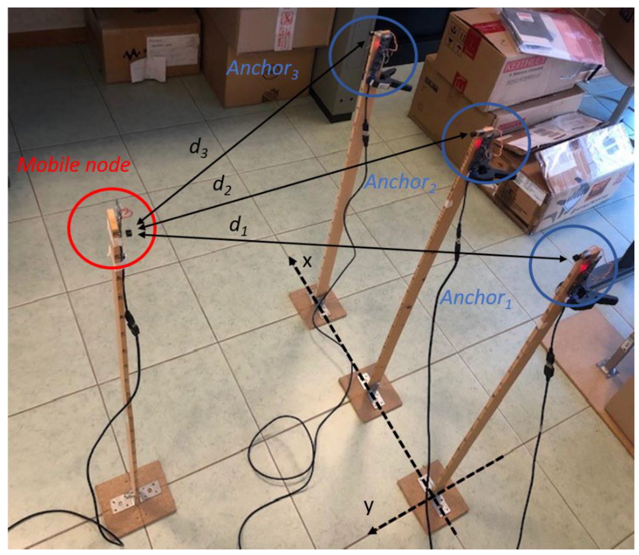
3. Setup and Operation

The considered setup, as shown in Figure 1, consists of a master node that triggers both the transmission and acquisition, a mobile node working as transmitter, and a set of anchor nodes that receive the signal emitted by the mobile node. The considered setup, as introduced in Section 2, was developed using the PSoC® 6 BLE Prototyping Kits equipped with a BLE radio interface [54]. Except for the master node, whose main function is to trigger the measurements by enabling all other nodes, all BLE nodes feature an ultrasound transceiver [32].
The considered setup makes use of the GAP profile, where the master node takes the role of broadcaster, while both the mobile node and a set of additional fixed position nodes used as anchors act as observers. The mobile node and the anchors also include the GAP peripheral role [53]. The master node periodically sends advertising events at regular intervals to the observer nodes with the aim to trigger both the transmission and acquisition. The observers continuously scan and process the master node advertising packets. Therefore, the mobile node transmits a sequence of ultrasound chirp pulses, and the anchors acquire the received signals and locally measure ToF by applying cross-correlation techniques as in [10,11] and convert them into distance estimations through the known speed of sound. Thus, the collected data are transmitted to a BLE-capable device hosting a dedicated app. When in range of the anchors, this device concentrates the range measurements and forwards them to a PC that finally runs a positioning algorithm to locate the mobile node.

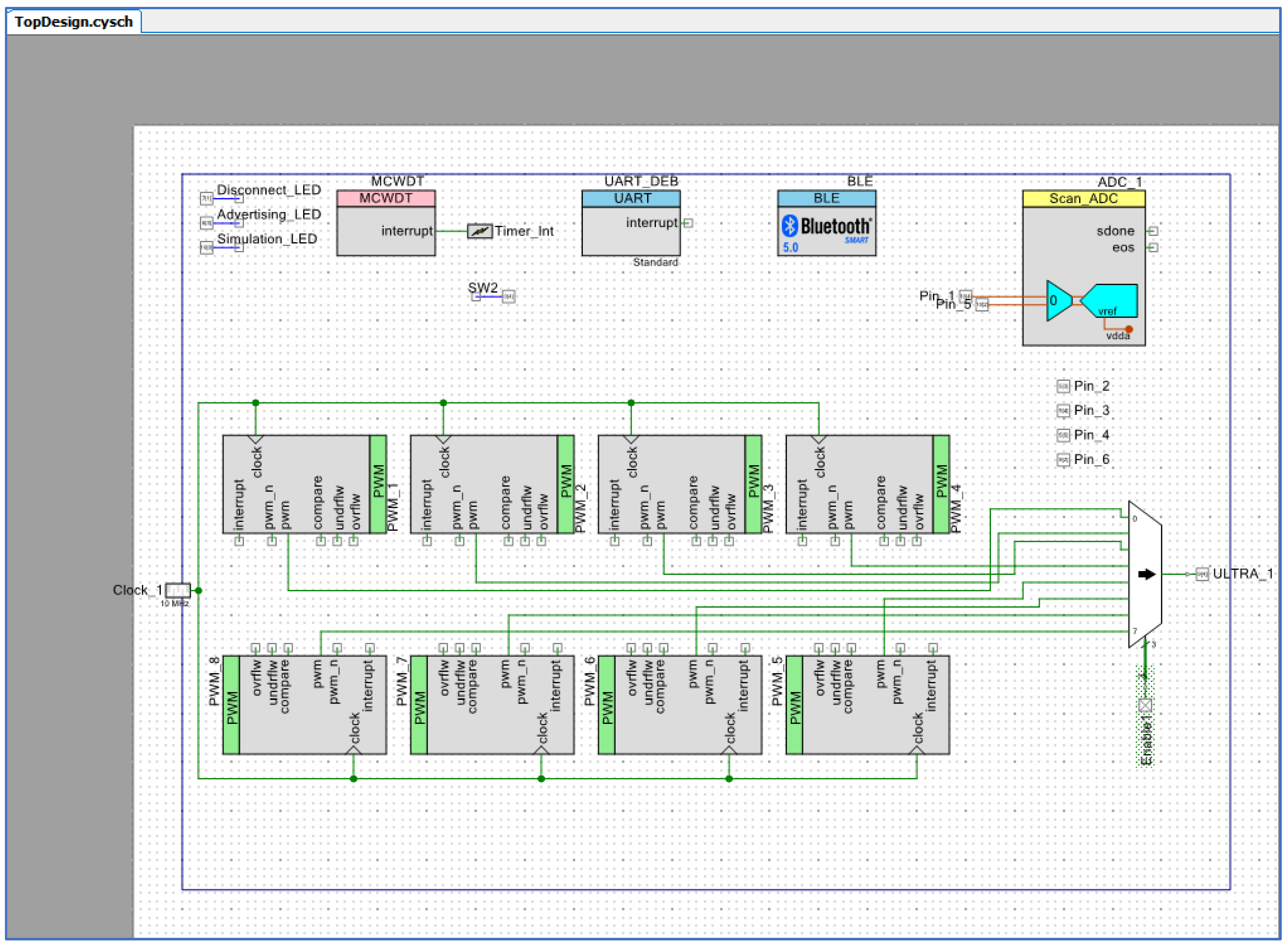
3.1. Wireless Triggering Using BLE

Time synchronization is considered a key factor in wireless sensor networks, especially for indoor positioning applications such as target tracking, which requires that the sensor nodes be time-synchronized with each other to locate moving objects or people. In particular, ToF measurements require accurate time synchronization between all the involved nodes and a reference time source node, ensuring a common time scale.
Over the past few years, various time-synchronization techniques for WSN that have been investigated apply packet synchronization techniques to trigger the network or to synchronize the clocks’ nodes [37,38,39,40,41,42,43,44,45,46]. Among the different available time-synchronization schemes, the one-way message exchange, the two-way message exchange, and the receiver–receiver synchronization appear to be the most widely used [39,46]. The one-way message exchange is a synchronization technique in which the master node broadcasts a unique message containing a time stamp to all the involved nodes for each session. Conversely, in the two-way message exchange, the master node periodically sends time-synchronization requests to the slave nodes, often employed in the sender–receiver approach. Finally, in the receiver–receiver synchronization approach, the nodes exchange broadcast timing information messages with each other [45].
One of the most popular synchronization methods developed for WSNs is Reference Broadcast Synchronization (RBS) [47,48]. The RBS consists of a master node that periodically transmits reference packets to all other network nodes. Thus, each receiver node measures the time of arrival of the reference packets according to its own local time. Finally, the nodes exchange the obtained reference time of arrival with each other to estimate the offset and skew. Moreover, the timing-sync protocol for sensor networks (TPSN) is based on the use of a classical approach that synchronizes two nodes instead of a set of receivers [49]. The protocol is basically divided into two steps: the discovery and the synchronization. In the discovery step, each node is assigned a layer starting from level 0. Note that the node of level 0 is named the root node. In the second step, the synchronization procedure takes place, so a node of level i synchronizes with a node of level i−1 and the procedure is iterated until all network nodes are synchronized to the root node. Meanwhile, the flooding time synchronization protocol (FTSP), proposed in [50], synchronizes transmitter and receiver or multiple receivers by using a single radio message. The FTSP can be considered the de-facto standard for time synchronization in WSN, since a much lower synchronization error is achieved with respect to the other mentioned synchronization methods [50]. Therefore, many proposed algorithms are based on its time synchronization scheme [47].
Nowadays, Internet of Things (IoT) applications are increasingly characterized by very restrictive requirements in terms of energy consumption limits, computational complexity, scalability, and synchronization accuracy. Consequently, we are faced with the expansion of a new generation of networks, usually characterized by small-sized sensors and actuators equipped with wireless connectivity and low-power and low-cost hardware [48].
In this regard, BLE is one of the available industrial oriented radio protocols that was widely discussed in recent years. As an example, in [51], the CheepSync mechanism, built on the existing Bluetooth v4.0 standard, is presented. The system consists of two main components: the beacon component and the control component. The beacon transmits a single advertisement packet to the control component. It is shown that CheepSync is capable of a time-synchronization average accuracy as low as 10 μs. Meanwhile, in [47], the BlueSync synchronization protocol, developed by using commercial platforms equipped with BLE, is proposed. It is shown that a time-synchronization error with a mean of about 320 ns within a time interval of 60 s can be achieved, using a frequency-drift estimation and compensation algorithm [47].
Note that a practical deployment can be characterized by the presence and closeness of various nodes deployed within a heterogeneous environment, making WSNs more sensitive to network congestion. The packet loss phenomenon can occur, thus affecting the whole time-synchronization process. Thus, when a practical implementation is considered, for instance, a microcontroller-based implementation, a considerable time-synchronization delay may occur [10]. The time-synchronization delay caused by the packet transmission process can therefore strongly affect the accuracy and precision of the time synchronization and can cause much larger errors than the required synchronization precision allows.
Moreover, the indoor propagation of RF signals can be affected by different factors, such as multipath phenomena, fast fading, strong human body absorption, non-line-of-sight (NLOS) propagation conditions, and clock frequency skew swinging; thus, the synchronization error will increase severely [37,38,39,40,41,42,43,44,45,46]. In addition, WSNs are typically characterized by size and cost constraints that limit resources such as power, memory space computational power and communications bandwidth.
In this regard, a simple, portable, and scalable time-synchronization approach based on a BLE protocol for a small size WSN is proposed in this work and an experimental evaluation was carried out. Note that the performed analysis and the implemented solution are based on the recently released BLE 5.0. The proposed approach can achieve microsecond-level synchronization, using existing hardware, services, and library routines [54,55], limiting the impact on battery life. Furthermore, in this work, time synchronization is obtained assuming that the master node periodically sends advertising packets to all observer nodes. Thus, it is assumed that the master node acts as broadcaster. According to the Bluetooth 5.0 core specification [54], the broadcaster role after device initialization transmits advertising events in sequence using one or more simultaneously of the three different advertising channels (named channel 37, channel 38 and channel 39). The time interval between two events is controlled by the advertising interval parameters spanning the interval from 20 ms to 10.240 ms in multiples of 0.625 ms. In the considered implementation, the advertising type is configured as non-connectable advertising packets, all advertising channels are considered, and the advertising interval is set to 2000 ms. On the other hand, the anchors that act as observers are configured to initiate the scan procedure for a period of 2000 ms and to process only the advertising packets received from the devices added in their whitelist, shared by the involved nodes. Moreover, the anchors are configured to act as peripheral. The peripheral starts advertising using connectable advertising packets and was initially configured to transmit data every 10 s to a connected central device, which is responsible for starting connections.
Thus, the synchronization procedure starts when the master node starts sending continuously advertising packets to all involved nodes. Moreover, a configurable digital output component available on the master node, hereinafter referred to as master trigger signal, is driven from the logic state low-to-high any time a packet is sent. In the same way, each involved node, acting as observer, changes its own digital output from the logic state low-to-high every time a packet is received. Thus, time synchronization is achieved with an error amounting to the offset between the rising edge of the master trigger signal and the rising edge of the digital output of the observer.

3.2. The Positioning Method: Principle and Operation

The positioning method, which was developed in a previous work [10], performs ToF measurements by transmitting ultrasound signals, given by
s ( t ) = s 0 ( T C t T C ) , s 0 ( t ) = { A 0 s i n ( 2 π ( f 0 + f 1 f 0 2 T C t ) t ) ,                             0 t T C 0 ,                                                                                                                   e l s e w h e r e  
where s 0 ( t ) describes a single linear chirp pulse; moreover, the lowest frequency and the highest frequency are respectively denoted by f 0 and f 1 , the chirp pulse duration is denoted by T C , and the transmitted signal amplitude is denoted by A 0 . Note that · represents the fractional part operator [10,11].
The estimation method acts as follows. The mobile node begins transmitting the pulse train; meanwhile, the anchors acquire the transmitted signals. Each anchor runs a peak search algorithm on the cross-correlation sequence between the acquired signal and a stored template of the transmitted ultrasound sequence.
The peak position corresponds to the time delay between the template and the acquired signal. If since the mobile node and the anchors are synchronized with each other, the time delay estimates the ToF. Then, the measured ToF is used to estimate the corresponding distance using the known speed of sound, v , leading to the system of equations given by
d i = v t i ,   i = 1 , , N , d i = ( x x i ) 2 + ( y y i ) 2 ,
where t i   is the ToF measured by the i-th anchor and d i is the distance between the mobile node and the i-th anchor. Moreover, the coordinates of the i-th anchor are denoted by (xi, yi), while the coordinates of the mobile node are denoted by (x,y). Thus, the node position (x,y) can be estimated using a hyperbolic multilateration algorithm as in [10,11].

4. Results

The proposed solution was experimentally evaluated by performing measurements in a real operational environment. At first, an analysis of the developed time-synchronization approach was carried out. Then, ToF-based distance estimations and positioning were performed. In the following subsection, the obtained results are shown and discussed.

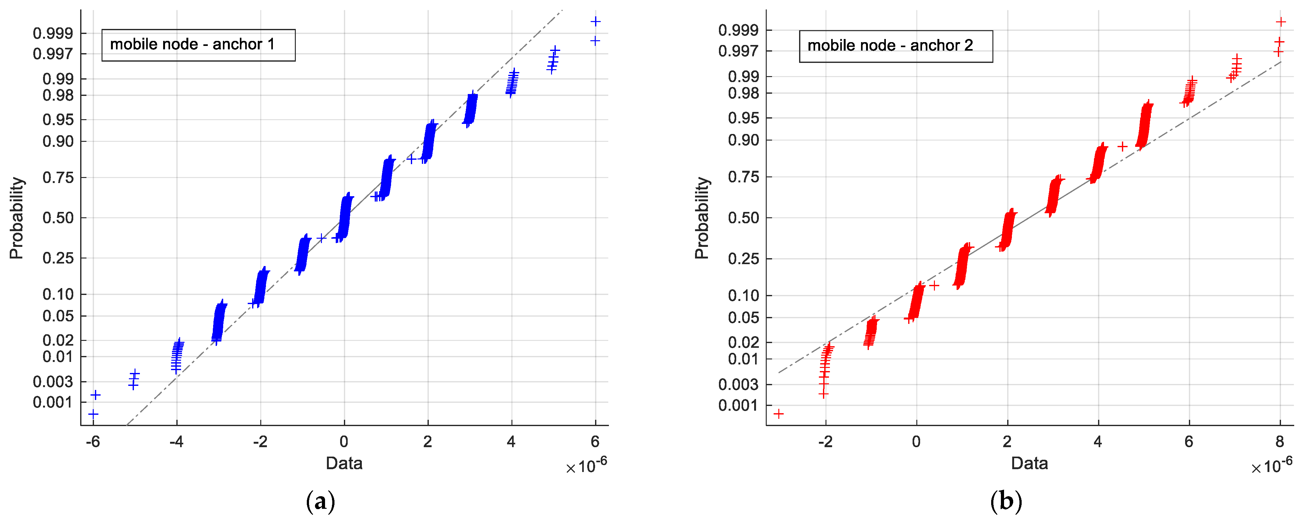
4.1. Time-Synchronization Analysis

To characterize the described delay, a measurement campaign was carried out. In particular, the time-synchronization delay between the beginning of the transmission of the mobile node and the beginning of the acquisition of each involved anchor was measured using a Teledyne LeCroy HDO9404 [56] oscilloscope with 4 channels. The delay between the rising edge of these signals was repeatedly measured, simultaneously collecting a record of 800 measurements for each of the mobile-anchor couplets. Figure 2 shows the time-synchronization delay waveforms between each considered couple of nodes. The presence of outliers (an outlier can be defined as a measurement result, the value of which diverges significantly from all other obtained results) can be observed, probably caused by loss of advertising packets, which leads to loss of time synchronization. Since no more than three outliers were observed out of 800 measurements, the synchronization was deemed reliable. Moreover, the low frequency of occurrence of outliers permits.
Table 1 shows the mean and the standard deviation of the time-synchronization delay before and after outlier removal. A delay with a mean of an order of magnitude of 10−6 s, and in one case 10−7 s, in the presence of outliers, was observed. Meanwhile, a delay with a mean of an order of magnitude ranging from 10−6 s to 10−8 s, in the absence of outliers, was observed. Moreover, a standard deviation of an order of magnitude of 10−5 s, in the presence of outliers, and a standard deviation of an order of magnitude of 10−6 s, in the absence of outliers, was observed. By considering the known equation of the propagation speed of sound and the ToF expected to be measured in an indoor environment, it can be deduced that the observed time-synchronization delays are a marginal source of error for both ToF measurements and distance estimations. To investigate the distribution of the synchronization error, the quantiles of a normal distribution with same mean and variance of the observed data were plotted against the quantiles of the observed data, leading to the normal probability plot shown in Figure 3. Note that a quasi-normal distribution in all 3 considered datasets was observed, the main difference being a discretization of the observed delays.

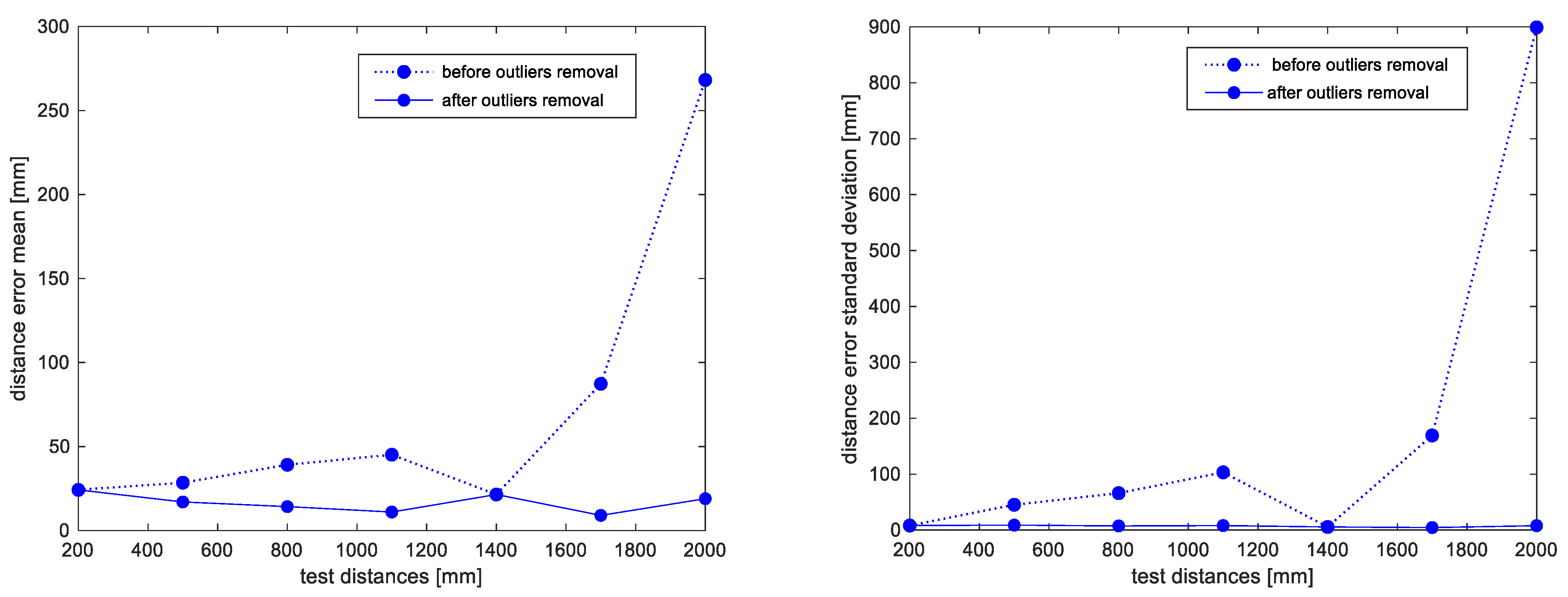
4.2. Distance Estimation
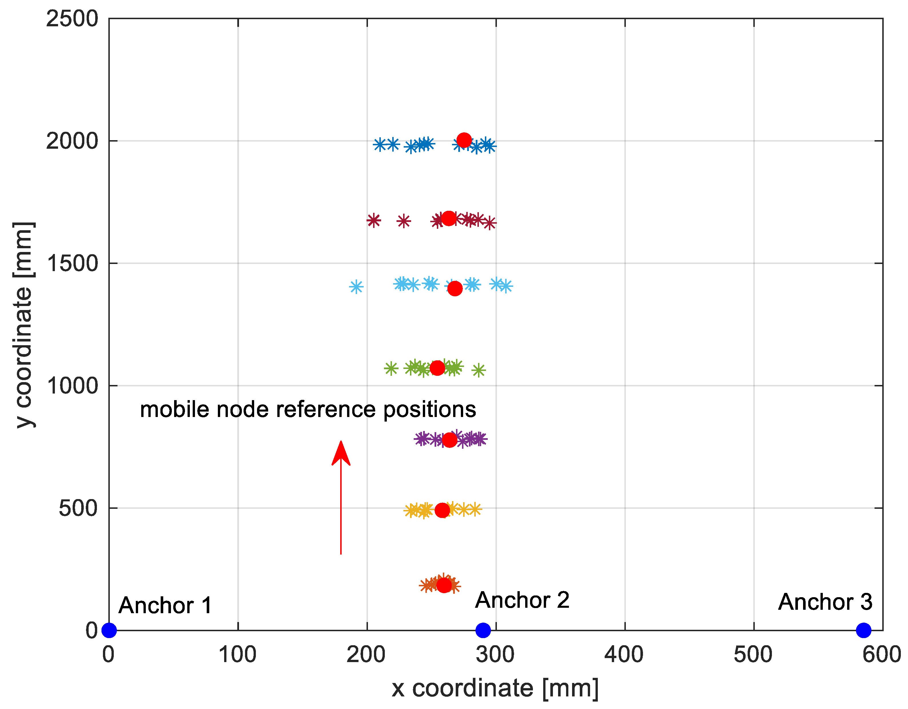
The positioning accuracy was evaluated with respect to the described phenomena, such as time-synchronization delay, multipath phenomenon, and maximum range of the system, by performing a measurement campaign in a real indoor environment.
As shown in Figure 4, the mobile node, mounted on a wooden pole, was consecutively placed in various positions simulating a portable scenario covering the operational area of about 2 m2. Meanwhile, the anchors were deployed in fixed positions, also mounted on wooden poles. Moreover, the measurement campaign was carried out using a mobile phone, due to the availability of a dedicated application, named CySmart, supplied with the PSoC® 6 BLE Prototyping Kit [54]. Thus, the CySmart application collects distance measurements during the connection state with each of the anchors. The application shows on the smartphone screen the distance value any time a measurement is available.
When a measurement campaign is planned, after supplying power to the mobile node and to the anchors, the estimation procedure is enabled by turning on the broadcaster. The transmitted signal is the periodic sequence of linear chirp pulses with unitary peak amplitude (1), spanning the [37.8–42.3] kHz interval in 5 ms, according to the specifications of the used Murata MA40S4R sensor [32]. Thus, the train pulse is generated using the pulse width modulator (PWM) components that are provided by the Component Catalog and Schematic Editor of the employed platforms, together with the MULTIPLEXER component and the digital output pins. As shown in Figure 5, where a screenshot of the top-level schematic file of the considered project is reported, to obtain a linear frequency change from 37.8 kHz to 42.3 kHz, 8 different PWM blocks were used, whose outputs were selected sequentially via the MULTIPLEXER component.
On the other hand, it is assumed that the receivers perform the acquisition of the transmitted signal and carry out distance estimations. The incoming signal is acquired by the PSoC on-board analog-to-digital converter (ADC) with a resolution of 12 bits and a sampling rate of fS = 100 ksample/s, corresponding to a sampling period tS = 1/fS = 10 μs. Thus, a record of M = 2000 samples is collected in about tacq = M·tS = 20 ms. The receivers estimate the ToF by calculating the cross-correlation between a locally stored template of the transmitted signal and the acquired records. Then, the envelope of the cross-correlation is obtained by using a Hilbert filter, and the index of the correlation peak is accurately extracted by feeding the three highest samples closest to the peak to a quadratic interpolation algorithm, applied to the correlation envelope [10,11]. The obtained interpolated value, which is a sample index corresponding to the time shift between the transmitted signal and a stored and normalized replica of the transmitted signal, is first multiplied by the sampling period and then converted into range estimations by using knowledge of the speed of sound in air. Then, the estimated ranges are sent to a connected central device every 10 s.
Data are shown and collected as text files to be able to process them and, finally, to estimate the position by using a simple least squares algorithm [10,11].
To validate the realized setup, a measurement campaign of the distance between each anchor and the mobile node was carried out. At first, anchor 1 (see Figure 1) was placed in a fixed position, and the mobile node instead was placed at 7 different positions. Figure 6 plots the mean and standard deviation of the estimated distance error before and after outlier removal for the considered couple of nodes (mobile node–anchor 1) against the true considered distance. For each testing position, 18 ToF and position measurements were obtained. Moreover, Table 2 shows the mean and standard deviation of the estimated distance error before and after outlier removal for the considered couple of nodes. Note that, after outlier removal, an accuracy on the order of a few centimeters is achievable. Moreover, in Figure 7, the mean and standard deviation after outlier removal of each considered couple of nodes are plotted. It is possible to observe also in this case that an accuracy on the order of a few centimeters is achievable.

4.3. Positioning

To gain further insight on the positioning performance, the measurements campaign was repeated considering three active anchors at the same time in a typical indoor environment featuring irregular geometry (e.g., walls, furniture), and operating in LOS condition. Since the activity is focused on the effects of wireless triggering, usage of multiple anchors is motivated by the need for assessing the capability of performing nearly simultaneous ToF measurements from multiple anchor nodes. Consequently, a simple setup was selected, with the minimum number of anchors required to perform planar positioning and without optimizing the anchors’ positions [11]. The anchors’ positions are shown in Figure 8 as blue dots. In particular, anchor 1 was placed in (0.0) mm, the anchor 2 was placed in (290.0) mm and the anchor 3 was placed in (585.0) mm. To define a ground truth, the mobile node positions were preliminarily obtained by manually measuring with a tape measure the distance between the mobile node and each anchor and then by applying the least squares algorithm to the measured distances. Note that even if a maximum distance of 2 m between each anchor and the mobile node was considered, the considered ultrasound transducers were used to achieve a range of about 4 m in the previous activity [57]. Figure 8 also shows the mobile node reference positions (red dots) and the position estimation results denoted with a cloud of asterisks of different colors for each considered reference position. It is possible to observe a deviation from the true value by a few centimeters in most measurements and in all cases below 10 centimeters. Moreover, note that when the distance from the anchors increases, the cloud of asterisks expands, and consequently, the accuracy of the position estimations decreases. The positioning accuracy may be improved by placing anchors so as to encompass the operational area from different directions [11], and by taking into account the directivity of the ultrasound transducers [58].
Figure 9 shows a boxplot of the positioning error that displays the distribution of the obtained results. Note that the positioning error was defined as the Euclidean distance between each considered reference position and the corresponding estimated position. It can be observed that the proposed approach has better accuracy when the mobile node is closer to the anchors. To gain additional insight on the achievable performance, the setup was modified, exploring the achievable measurement rate and profiling the main activities required by the ToF measurement. Initial tests showed that to achieve stable performance, the scan time tW needed to be set to values larger than 2 s. The programmed measurement period tM, originally set to 10 s when programming the anchor nodes as peripherals, was gradually reduced, showing that for values larger than the programmed scan window duration tW, the measurement was completed correctly, while for tM < tW the measurement procedure became unstable.
Hence, the adopted system permits a maximum measurement rate of almost 30 measurements per minute. This behavior was further investigated by observing that when tM > tW, the anchor nodes may collect ToF measurements belonging to different scan windows. On the other hand, tW is lower bounded by
tToF = tacq + tProc,
which is the summation of the data acquisition time tacq, equaling 20 ms for a record of 2000 samples collected with a rate of 100 ksample/s, with the processing time tProc, given by
t P r o c t x c o r r + t H i l b e r t + t m a x , s e a r c h ,
where txcorr is the time required to evaluate the correlation sequence, tHilbert is the time required to compute the Hilbert transform of the correlation sequence, and tmax,search is the time required to perform the maximum search. Note that, provided that the data processing is completed immediately after the data acquisition, (3) describes the minimum time required to complete a ToF measurement. By measuring each processing time contribution with a digital oscilloscope we obtained txcorr ≅ 2.12 s, tHilbert ≅ 16 ms, and tmax,search ≅ 500 μs. In order to provide a more comprehensive description of the observed behavior, Figure 10 shows a timing diagram where all the time contributions required to perform ToF measurements are depicted. These results seemingly prove the assumption that the bottleneck limiting the measurement rate is actually the processing time tproc, and show that tproc is dominated by txcorr.
Thus, the ToF measurement rate may be improved by replacing the PSoC nodes with more powerful processors or by using more efficient algorithms. In particular, since the cross-correlation is currently computed using a time domain algorithm, replacing it with a fast Fourier transform based algorithm may reduce the computational complexity from O(M2) = 4 × 10⁶ to O(M⋅log2(M)) ≅ 2.19 × 10⁴, reducing txcorr by two orders of magnitude and reducing tproc to a few tens of milliseconds.
The processing time of the positioning algorithm was also profiled. This algorithm is a nonlinear fitting realized by a Matlab script, running on a PC equipped with an Intel I7 3.6 GHz CPU, 8 GB RAM, and a Windows 10 Operating System. The algorithm was profiled by estimating the completion time using the Matlab tic and toc functions over N = 110 position measurements, obtaining a mean time of 12 ms and a standard deviation of 0.58 ms. These results suggest that the positioning algorithm has a low computational cost and may be moved to a smartphone, eventually replacing the nonlinear fitting with a best linear unbiased estimator or with a Kalman filter to perform sensor fusion with inertial measurements.

5. Conclusions

In this work, a distributed positioning system based on ToF measurements and ultrasound signals with centimeter-level accuracy and compatible with commercial hardware platforms was developed. Time synchronization between transmitters and receivers is achieved using the BLE technology. The proposed synchronization scheme is based on a simple packet synchronization technique, without the use of compensation or adjustment algorithms, and was validated experimentally using Bluetooth v5.0 transceivers.
It was shown that a level of synchronization compatible with Time of Flight (ToF)-based positioning can be achieved, with an error of a few microseconds. Position estimations were performed as well, and the experimental results showed good accuracy in indoor environments when LOS conditions were available. The proposed system is low-cost, since the components of the five nodes in the proposed system can be obtained for less than EUR 200. Coupled with the BLE 5.0 addressing scheme, this makes the proposed solution scalable for a wide range of applications.
The results show that an accurate and low-cost positioning system can be developed on the basis of ToF measurements on ultrasound transmissions triggered by BLE RF transmissions. Moreover, the results suggest that the proposed system can be considered an interesting and competitive solution for WSN and IoT applications. Future developments of the described activity will include the improvement of the measurement rate, the extension of the proposed solution to 3D scenarios, and the use of MEMS ultrasound sensors.

Author Contributions

Conceptualization, A.M., P.C., A.C. and A.D.A.; methodology, A.C.; software, A.C. and A.D.A.; validation, A.C., A.M. and A.D.A.; investigation, A.C. and A.M.; data curation, A.C. and A.D.A.; writing—original draft preparation, A.C. and A.M.; writing—review and editing, A.C., P.C., A.D.A. and A.M. All authors have read and agreed to the published version of the manuscript.

Funding

This research received no external funding.

Conflicts of Interest

The authors declare no conflict of interest.

References

  1. Macagnano, D.; Destino, G.; Abreu, G. Indoor Positioning: A Key Enabling Technology for Iot Applications. In Proceedings of the 2014 IEEE World Forum on Internet of Things (WF-IoT), Seoul, Korea, 6–8 March 2014; pp. 117–118. [Google Scholar] [CrossRef]
  2. Sadowski, S.; Spachos, P.; Plataniotis, K.N. Memoryless Techniques and Wireless Technologies for Indoor Localization with the Internet of Things. IEEE Internet Things J. 2020, 7, 10996–11005. [Google Scholar] [CrossRef]
  3. Monfared, S.; Copa, E.I.P.; de Doncker, P.; Horlin, F. AoA-Based Iterative Positioning of IoT Sensors with Anchor Selection in NLOS Environments. IEEE Trans. Veh. Technol. 2021, 70, 6211–6216. [Google Scholar] [CrossRef]
  4. Pascale, F.; Adinolfi, E.; Avagliano, M.; Giannella, V.; Salas, A. A Low Energy IoT Application Using Beacon for Indoor Localization. Appl. Sci. 2021, 11, 4902. [Google Scholar] [CrossRef]
  5. Mautz, R. Overview of current indoor positioning systems. Geod. Cartogr. 2009, 35, 18–22. [Google Scholar] [CrossRef]
  6. Zafari, F.; Gkelias, A.; Leung, K.K. A Survey of Indoor Localization Systems and Technologies. IEEE Commun. Surv. Tutor. 2019, 21, 2568–2599. [Google Scholar] [CrossRef] [Green Version]
  7. Medina, C.; Segura, J.C.; de La Torre, A. Ultrasound Indoor Positioning System Based on a Low-Power Wireless Sensor Network Providing Sub-Centimeter Accuracy. Sensors 2013, 13, 3501–3526. [Google Scholar] [CrossRef] [Green Version]
  8. Perez, M.C.; Gualda, D.; Villadangos, J.M.; Urena, J.; Pajuelo, P.; Diaz, E.; Garcia, E. Android Application for Indoor Positioning of Mobile Devices Using Ultrasonic Signals. In Proceedings of the 2016 International Conference on Indoor Positioning and Indoor Navigation (IPIN), Alcala de Henares, Spain, 4–7 October 2016; pp. 1–7. [Google Scholar] [CrossRef]
  9. Diaz, E.; Perez, M.C.; Gualda, D.; Villadangos, J.M.; Urena, J.; Garcia, J.J. Ultrasonic Indoor Positioning for Smart Environments: A Mobile Application. In Proceedings of the 2016 International Conference on Indoor Positioning and Indoor Navigation (IPIN), Alcala de Henares, Spain, 4–7 October 2016; pp. 280–285. [Google Scholar] [CrossRef]
  10. Comuniello, A.; de Angelis, A.; de Angelis, G.; Moschitta, A. Ultrasound Time of Flight Based Positioning Using the Bluetooth Low Energy Protocol. In Proceedings of the 2019 IEEE International Symposium on Measurements & Networking (M&N), Catania, Italy, 8–10 July 2019; pp. 1–6. [Google Scholar] [CrossRef]
  11. Comuniello, A.; Moschitta, A.; de Angelis, A. Ultrasound TDoA Positioning Using the Best Linear Unbiased Estimator and Efficient Anchor Placement. IEEE Trans. Instrum. Meas. 2020, 69, 2477–2486. [Google Scholar] [CrossRef]
  12. Santoni, F.; de Angelis, A.; Moschitta, A.; Carbone, P. MagIK: A Hand-Tracking Magnetic Positioning System Based on a Kinematic Model of the Hand. IEEE Trans. Instrum. Meas. 2021, 70, 1–13. [Google Scholar] [CrossRef]
  13. Milano, F.; Cerro, G.; Santoni, F.; de Angelis, A.; Miele, G.; Rodio, A.; Moschitta, A.; Ferrigno, L.; Carbone, P. Parkinson’s Disease Patient Monitoring: A Real-Time Tracking and Tremor Detection System Based on Magnetic Measurements. Sensors 2021, 21, 4196. [Google Scholar] [CrossRef]
  14. Ferrigno, L.; Laracca, M.; Milano, F.; Cerro, G.; Bellitti, P.; Serpelloni, M.; Piedrafita, O.C. Magnetic Localization System for Short-Range Positioning: A Ready-to-Use Design Tool. IEEE Trans. Instrum. Meas. 2021, 70, 1–9. [Google Scholar] [CrossRef]
  15. Subedi, S.; Pyun, J.-Y. A Survey of Smartphone-Based Indoor Positioning System Using RF-Based Wireless Technologies. Sensors 2020, 20, 7230. [Google Scholar] [CrossRef]
  16. Santinelli, G.; Giglietti, R.; Moschitta, A. Self-Calibrating Indoor Positioning System Based on Zigbee® Devices. In Proceedings of the IEEE International Instrumentation and Measurement Technology Conference (I2MTC 2009), Singapore, 5–7 May 2009; pp. 1205–1210. [Google Scholar]
  17. Zhuang, Y.; Yang, J.; Li, Y.; Qi, L.; El-Sheimy, N. Smartphone-Based Indoor Localization with Bluetooth Low Energy Beacons. Sensors 2016, 16, 596. [Google Scholar] [CrossRef] [Green Version]
  18. Paterna, V.C.; Augé, A.C.; Aspas, J.P.; Bullones, M.A.P. A Bluetooth Low Energy Indoor Positioning System with Channel Diversity, Weighted Trilateration and Kalman Filtering. Sensors 2017, 17, 2927. [Google Scholar] [CrossRef] [Green Version]
  19. Zuo, Z.; Liu, L.; Zhang, L.; Fang, Y. Indoor Positioning Based on Bluetooth Low-Energy Beacons Adopting Graph Optimization. Sensors 2018, 18, 3736. [Google Scholar] [CrossRef] [Green Version]
  20. Ke, H.; Ke, H.; Xuecheng, D. A Hybrid Method to Improve the BLE-Based Indoor Positioning in a Dense Bluetooth Environment. Sensors 2019, 19, 424. [Google Scholar]
  21. Wang, B.; Wang, Y.; Qiu, X.; Shen, Y. BLE Localization with Polarization Sensitive Array. IEEE Wirel. Commun. Lett. 2021, 10, 1014–1017. [Google Scholar] [CrossRef]
  22. Spachos, P.; Plataniotis, K.N. BLE Beacons for Indoor Positioning at an Interactive IoT-Based Smart Museum. IEEE Syst. J. 2020, 14, 3483–3493. [Google Scholar] [CrossRef] [Green Version]
  23. Yu, Y.; Chen, R.; Chen, L.; Zheng, X.; Wu, D.; Li, W.; Wu, Y. A Novel 3-D Indoor Localization Algorithm Based on BLE and Multiple Sensors. IEEE Internet Things J. 2021, 8, 9359–9372. [Google Scholar] [CrossRef]
  24. Bai, L.; Ciravegna, F.; Bond, R.; Mulvenna, M. A Low Cost Indoor Positioning System Using Bluetooth Low Energy. IEEE Access 2020, 8, 136858–136871. [Google Scholar] [CrossRef]
  25. Mackey, A.; Spachos, P.; Song, L.; Plataniotis, K.N. Improving BLE Beacon Proximity Estimation Accuracy Through Bayesian Filtering. IEEE Internet Things J. 2020, 7, 3160–3169. [Google Scholar] [CrossRef] [Green Version]
  26. Indoor Positioning Systems Based on BLE Beacons. Available online: https://locatify.com/blog/indoor-positioning-systems-ble-beacons/ (accessed on 7 November 2021).
  27. Morgado, F.; Martins, P.; Caldeira, F. Beacons positioning detection, a novel approach. Procedia Comput. Sci. 2019, 151, 23–30. [Google Scholar] [CrossRef]
  28. iBeacon. Available online: https://developer.apple.com/ibeacon/ (accessed on 12 April 2019).
  29. Valencia-Velasco, J.; Longoria-Gandara, O.; Aldana-Lopez, R.; Pizano-Escalante, L. Low-Complexity Maximum-Likelihood Detector for IoT BLE Devices. IEEE Internet Things J. 2020, 7, 4737–4745. [Google Scholar] [CrossRef]
  30. Wang, W.; Marelli, D.; Fu, M. Fingerprinting-Based Indoor Localization Using Interpolated Preprocessed CSI Phases and Bayesian Tracking. Sensors 2020, 20, 2854. [Google Scholar] [CrossRef] [PubMed]
  31. Cengiz, K. Comprehensive Analysis on Least-Squares Lateration for Indoor Positioning Systems. IEEE Internet Things J. 2021, 8, 2842–2856. [Google Scholar] [CrossRef]
  32. Murata Manufacturing Co., Ltd. MA40S4S/MA40S4R Ultrasonic Transducers Overview. Available online: https://www.murata.com/en-us/products/sensor/overview/item/ma40s4 (accessed on 7 November 2021).
  33. Analog Bottom Port Microphone with Frequency Response up to 80 kHz for Ultrasound Analysis and Predictive Maintenance Applications. Available online: https://www.st.com/en/mems-and-sensors/imp23absu.html (accessed on 7 November 2021).
  34. Wang, H.; Ma, Y.; Yang, H.; Jiang, H.; Ding, Y.; Xie, H. MEMS Ultrasound Transducers for Endoscopic Photoacoustic Imaging Applications. Micromachines 2020, 11, 928. [Google Scholar] [CrossRef] [PubMed]
  35. Marcaletti, A.; Rea, M.; Giustiniano, D.; Lenders, V.; Fakhreddine, A. Filtering Noisy 802.11 Time-of-Flight Ranging Measurements. In Proceedings of the 10th ACM International on Conference on emerging Networking Experiments and Technologies, Sydney, Australia, 2–5 December 2014; pp. 13–20. [Google Scholar] [CrossRef] [Green Version]
  36. Pascacio, P.; Casteleyn, S.; Torres-Sospedra, J.; Lohan, E.; Nurmi, J. Collaborative Indoor Positioning Systems: A Systematic Review. Sensors 2021, 21, 1002. [Google Scholar] [CrossRef]
  37. Su, W.; Akyildiz, I. Time-diffusion synchronization protocol for wireless sensor networks. IEEE/ACM Trans. Netw. 2005, 13, 384–397. [Google Scholar] [CrossRef]
  38. Ferrigno, L.; Paciello, V.; Pietrosanto, A. Experimental Characterization of Synchronization Protocols for Instrument Wireless Interface. IEEE Trans. Instrum. Meas. 2010, 60, 1037–1046. [Google Scholar] [CrossRef]
  39. Kosanovic, M.R.; Stojcev, M.K. Delay Compensation Method for Time Synchronization in Wireless Sensor Networks. In Proceedings of the 10th International Conference on Telecommunication in Modern Satellite Cable and Broadcasting Services (TELSIKS), Nis, Serbia, 5–8 October 2011; pp. 623–629. [Google Scholar] [CrossRef]
  40. Wu, J.; Zhang, L.; Bai, Y.; Sun, Y. Cluster-Based Consensus Time Synchronization for Wireless Sensor Networks. IEEE Sensors J. 2015, 15, 1404–1413. [Google Scholar] [CrossRef]
  41. Cena, G.; Scanzio, S.; Valenzano, A.; Zunino, C. Implementation and Evaluation of the Reference Broadcast Infrastructure Synchronization Protocol. IEEE Trans. Ind. Inform. 2015, 11, 801–811. [Google Scholar] [CrossRef]
  42. Wang, Z.; Zeng, P.; Zhou, M.; Li, D.; Wang, J. Cluster-Based Maximum Consensus Time Synchronization for Industrial Wireless Sensor Networks. Sensors 2017, 17, 141. [Google Scholar] [CrossRef] [Green Version]
  43. Zhang, D.; Yuan, Y.; Bi, Y. A Design of a Time Synchronization Protocol Based on Dynamic Route and Forwarding Certification. Sensors 2020, 20, 5061. [Google Scholar] [CrossRef] [PubMed]
  44. Chalapathi, G.S.S.; Chamola, V.; Gurunarayanan, S.; Sikdar, B. E-SATS: An Efficient and Simple Time Synchronization Protocol for Cluster- Based Wireless Sensor Networks. IEEE Sens. J. 2019, 19, 10144–10156. [Google Scholar] [CrossRef]
  45. Wang, H.; Shao, L.; Li, M.; Wang, B.; Wang, P. Estimation of Clock Skew for Time Synchronization Based on Two-Way Message Exchange Mechanism in Industrial Wireless Sensor Networks. IEEE Trans. Ind. Inform. 2018, 14, 4755–4765. [Google Scholar] [CrossRef]
  46. Huan, X.; Kim, K.S.; Lee, S.; Lim, E.G.; Marshall, A. A Beaconless Asymmetric Energy-Efficient Time Synchronization Scheme for Resource-Constrained Multi-Hop Wireless Sensor Networks. IEEE Trans. Commun. 2020, 68, 1716–1730. [Google Scholar] [CrossRef] [Green Version]
  47. Asgarian, F.; Najafi, K. BlueSync: Time Synchronization in Bluetooth Low Energy with Energy Efficient Calculations. IEEE Internet Things J. 2021. [Google Scholar] [CrossRef]
  48. Elson, J.; Girod, L.; Estrin, D. Fine-grained network time synchronization using reference broadcasts. ACM SIGOPS Oper. Syst. Rev. 2002, 36, 147–163. [Google Scholar] [CrossRef]
  49. Ganeriwal, S.; Kumar, R.; Srivastava, M.B. Timing-Sync Protocol for Sensor Networks. In Proceedings of the 1st International Conference on Embedded Networked Sensor Systems, Los Angeles, CA, USA, 5–7 November 2003; pp. 138–149. [Google Scholar]
  50. Maróti, M.; Kusy, B.; Simon, G.; Lédeczi, Á. The Flooding Time Synchronization Protocol. In Proceedings of the 2nd International Conference on Embedded Networked Sensor Systems, Baltimore, MD, USA, 3–5 November 2004; pp. 39–49. [Google Scholar]
  51. Sridhar, S.; Misra, P.; Gill, G.S.; Warrior, J. Cheepsync: A time synchronization service for resource constrained bluetooth le advertisers. IEEE Commun. Mag. 2015, 54, 136–143. [Google Scholar] [CrossRef] [Green Version]
  52. Bluetooth® Specifications-The Building Blocks of All Bluetooth Devices. Available online: https://www.bluetooth.com/specifications/ (accessed on 7 November 2021).
  53. Bluetooth® Specifications-Specifications List. Available online: https://www.bluetooth.com/specifications/specs/ (accessed on 7 November 2021).
  54. Cypress PSoC® 6 BLE Datasheet. Available online: https://www.cypress.com/file/385916/download (accessed on 11 March 2021).
  55. PSoC™ Creator. Available online: https://www.cypress.com/products/psoc-creator-integrated-design-environment-ide (accessed on 7 November 2021).
  56. WavePro HD Oscilloscopes. Available online: https://teledynelecroy.com/oscilloscope/wavepro-hd-oscilloscope (accessed on 19 December 2021).
  57. De Angelis, A.; Moschitta, A.; Carbone, P.; Calderini, M.; Neri, S.; Borgna, R.; Peppucci, M. Design and Characterization of a Portable Ultrasonic Indoor 3-D Positioning System. IEEE Trans. Instrum. Meas. 2015, 64, 2616–2625. [Google Scholar] [CrossRef]
  58. Rivard, F.; Bisson, J.; Michaud, F.; Létourneau, D. Ultrasonic Relative Positioning for Multi-Robot Systems. In Proceedings of the 2008 IEEE International Conference on Robotics and Automation, Pasadena, CA, USA, 19–23 May 2008. [Google Scholar]
Figure 1. Block diagram of the considered setup.
Electronics 11 00111 g001
Figure 2. (ac) show the time-synchronization delay waveforms between each considered couple of nodes.
Electronics 11 00111 g002
Figure 3. (ac) show the normal probability plot of the time-synchronization delay waveforms (outliers removed) between each considered couple of nodes.
Electronics 11 00111 g003aElectronics 11 00111 g003b
Figure 4. Picture of the experimental setup.
Electronics 11 00111 g004
Figure 5. Configuration of the transmitter node, as shown in the TopDesign view of the Cypress PSoC Creator IDE.
Electronics 11 00111 g005
Figure 6. Mean (left) and standard deviation (right) of the estimated distance error for the couple of nodes (mobile node–anchor 1).
Electronics 11 00111 g006
Figure 7. Distance error mean (left) and standard deviation (right) for each considered couple of nodes after outlier removal.
Electronics 11 00111 g007
Figure 8. The considered experimental setup and position estimation results.
Electronics 11 00111 g008
Figure 9. The boxplot of the positioning error.
Electronics 11 00111 g009
Figure 10. Timing diagram profiling the main activities required by the ToF measurement.
Electronics 11 00111 g010
Table 1. Mean and standard deviation of the measured time-synchronization delays for each considered couple of nodes.
Considered Couples of NodesTime-Synchronization Delay Mean [s]Time-Synchronization Delay Standard Deviation [s]
OutliersNo-OutliersOutliersNo-Outliers
mobile node-anchor 11.2864 × 10−64.0495 × 10−82.7896 × 10−51.6908 × 10−6
mobile node-anchor 21.5992 × 10−62.3773 × 10−63.8217 × 10−51.7745 × 10−6
mobile node-anchor 33.0095 × 10−79.5101 × 10−73.9568 × 10−51.7647 × 10−6
Table 2. Mean and standard deviation of the estimated distance error for the couple of nodes (mobile node–anchor 1).
Considered True Distances
[mm]
Distance Error Mean
[mm]
Distance Error Standard Deviation
[mm]
OutliersNo-OutliersOutliersNo-Outliers
200242488
5002817459
8003914667
110045111038
1400212155
17008791694
2000268188998
Publisher’s Note: MDPI stays neutral with regard to jurisdictional claims in published maps and institutional affiliations.

