Abstract
To enhance the robust stability of the dc-link voltage in the photovoltaic (PV) grid-connected system, a modified linear active disturbance rejection control (LADRC)-based regulation strategy is presented in this paper. The proposed control strategy is equipped with the cascaded extended state observer, which can supplement the disturbance information not estimated by the conventional one, thereby achieving a relatively fast and accurate disturbance reconstruction. The tracking performance and disturbance rejection performance of the modified LADRC are discussed and studied in the frequency domain. Finally, the experimental results are provided to verify the theoretical analysis.
1. Introduction
Extensive use of fossil fuels has caused more and more serious damage to the living environment of human beings and has led to ecological deterioration [1]. After years of exploration, grid-connected photovoltaic (PV) power plants have become the future development direction and research focus [2]. As the interface between renewable and the grid, grid-connected inverters play a vital role in the process of high-efficiency power conversion and high-quality power supply [3,4]. The control of the inverter is not only responsible for regulating the grid-connected current, but also must maintain a stable voltage across the dc-link capacitor [5]. Notably, if the dc-link voltage is not correctly controlled, the performance of the system would be severely degraded and even trigger related protection devices [6]. Therefore, the control performance of the dc-link voltage can be regarded as an important indicator to measure the reliability of grid-connected systems.
For PV grid-connected inverters, a dual-loop control structure under the dq synchronous reference frame (SRF) is generally adopted [7]. The outer voltage loop maintains a constant dc-link voltage by balancing the power flow in the system, and the inner current loop is responsible for power quality issues and harmonic protection [8]. However, in the presence of active power disturbances, the dc-link voltage is prone to fluctuations. These active power disturbances are mainly divided into three categories, namely: (1) Variations in climatic conditions, such as temperature and solar irradiance [9,10]; (2) voltage sag fault on the grid; and (3) inevitable power exchange fluctuations between the dc side of the inverter and the grid. Besides, the inverter itself is also a sensitive system with non-constant parameters and non-linear variations. All factors above have caused problems for realizing robust dc-link voltage control.
To enhance the robustness of the dc-link voltage under multi-source disturbances, a feedforward control is integrated into the outer loop to compensate for the disturbance caused by active power [11]. However, this feedforward control requires additional sensors, which is undesirable from the standpoint of reliability and cost. An adaptive control method that can support the dc-link voltage stability during grid sag fault is proposed in [12]. When an asymmetrical grid fault occurs, this control method can stabilize the dc-link voltage within the rated range by attenuating the double-line-frequency ripple. Also, some advanced control schemes have been developed for grid-connected power converters, such as sliding-mode control [13], internal model control [14], and neural networks [15].
Recently, control strategies, using observers, have also been implemented in dc-link voltage regulation [16,17,18]. Considering the fault condition of the dc-link voltage sensor, a control method based on Luenberger observer was employed in [16], which can improve system stability through fault-tolerant control. In [17], a control scheme using nonlinear disturbance observer (Dob) is conceived to suppress the fluctuation range of the dc-link voltage when the capacitance parameter variations. In particular, this method does not need to add additional sensors, which is conducive to realizing the “plug-and-play” of distributed generators in the microgrid. Besides, the work presented in [18] combines extended state observer (ESO) with sliding mode control to force the inner loop current to track the set point, thereby indirectly enhancing the transient performance of the dc-link voltage. ESO breaks the limitations of the Luenberger observer and DoB requiring accurate plant models, and has been widely used as an observer to estimate the disturbances. ESO was originally proposed in the structure of active disturbance rejection control (ADRC) [19].
In the ADRC framework, the internal uncertainties and external disturbances of the plant are regarded as a “generalized disturbance”, while ESO and feedback control law are constructed to estimate and compensate for it. Based on strong tolerance to disturbances, ADRC has shown broad prospects in engineering applications. However, the non-linear structure and complex parameter tunings pose challenges for its theoretical analysis. For the convenience of application, a linear ADRC (LADRC) is first discussed in [20] through the pole placement technique. The formula description of LADRC is relatively uncomplicated, and the characteristics of its resulting control system could be explored in the frequency domain, such as stability, tracking and disturbance rejection performance [21,22]. Obviously, the overall properties of LADRC-based control systems are closely related to the estimation ability of generalized disturbance [23].
In this paper, a modified LADRC-based dc-link voltage control strategy is particularly developed in a disturbed PV grid-connected system, in order to improve the dynamics and disturbance tolerance under variable operating conditions. Cascaded linear ESO (LESO) is employed to guarantee relatively accurate estimation of generalized disturbance. The remainder of this paper is organized as follows. In Section 2, the stability problem under active power disturbances is revealed through the dynamic modeling of the dc link, and the commonly used dual-loop control structure is briefly introduced. In Section 3 and Section 4, the design procedure and performance investigation of the modified LADRC are presented respectively. In Section 5, the experimental comparison results are provided to verify the effectiveness of the proposed modified LADRC. Finally, the conclusions are indicated in Section 6.
2. Problem Formulation
The analysis and research on the dc-link voltage in this paper are based on the two-stage PV grid-connected system, described in Figure 1, where the front stage and the rear stage have independent topology and control objectives [24]. The realization of maximum power point tracking (MPPT) and voltage boost conversion is the main attribute of the front stage dc/dc link [25]. The rear stage dc/ac link, which has the following tasks [8]:
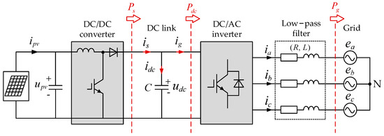
Figure 1.
Configuration and power flow of two-stage PV grid-connected system, where denotes the dc-link capacitor; denotes the dc-link voltage; is the output current of the boost converter; is the current flowing through the dc-link capacitor; is the current input to the inverter by the dc link; , , , represent the grid phase current; , , represent the phase voltage of the grid; R and L represent the filter resistance, and inductance, respectively.
- dc-link voltage control within safe operational range;
- active current control on the grid side;
- ensure the high quality of the power injected into the grid;
- grid synchronization.
There is a capacitor between the front stage and the rear stage, which can alleviate the transient fluctuation of the dc-link voltage and attenuate the high-frequency ripple component [6]. Before starting the robust controller design, the power disturbances of the dc link and its control investigation are briefly described.
2.1. Power Disturbances Analysis of DC Link
From Figure 1, the active power relationship across the dc link can be described as,
where, is the active power flowing through the boost circuit, . is the inverter dc-side terminal power .
In dq SRF, assuming that the grid voltage is balanced, the active power of the grid side can be expressed as,
where and are the dq axis components of the grid voltage; and are the dq axis components of the grid current. Align the d-axis in the SRF with the grid voltage vector, then is equal to the phase voltage magnitude, [26]:
If the power loss of the electronic converters and the ac-side filter is not considered, the dc-side terminal power is equal to the grid-connected power [17]. Considering this scenario, Equation (1) can be rewritten as:
Equation (4) illustrates that the dynamics of the dc-link voltage is affected by the power relationship between the front stage and the rear stage.
When the PV grid-connected system is in a steady state, the dc-link voltage is maintained at the nominal value, with . However, the variations of ambient temperature, solar irradiance, grid voltage and other uncertain factors would lead to the imbalance between and , forcing the dc-link voltage to fluctuate. At this time, the current flowing through the dc side capacitor changes more drastically, which seriously threatens the safety of the device. Therefore, it is of practical significance to design a robust dc-link voltage controller.
2.2. Control Investigation of DC link.
From Figure 1, the dynamic model of the dc link can be presented as:
Assuming that the dc link has been well controlled, , the relationship between and can be derived as:
This approximation method ignores the interactive influence of the current loop and the voltage loop, which can reduce the complexity of the control system design without significantly affecting the performance [6].
Substituting Equation (6) into Equation (5) yields,
which illustrates that the control of the dc-link voltage can actually be carried out around the d-axis component of the grid current. Furthermore, this can also explain why can be used as the output of the outer-loop voltage controller in the dual-loop structure.
Figure 2 presents a commonly used dual-loop control structure, where the reference system conversion modules are used to generate the components of the control variable on the dq-axis and the modulation signal. The voltage controller is responsible for supporting the control stability of the dc-link voltage and synthesizing the required d-axis current reference. The current controller regulates the grid-side power by controlling the dq-axis current to track the given reference [27]. As for the q-axis current, its reference is generally set to zero to achieve unity power factor grid connection. The frequency and phase required to perform the coordinate system transformation are generated by a phase-locked loop (PLL).
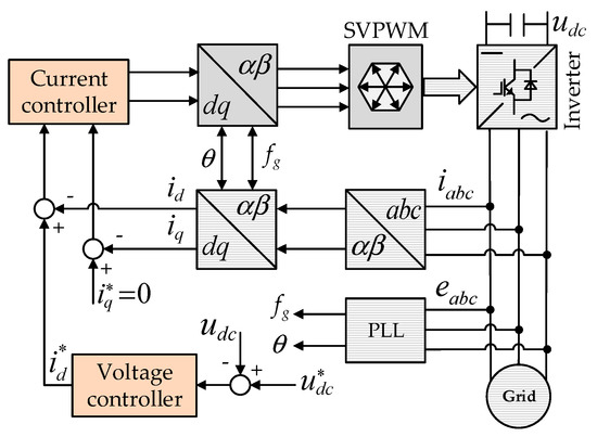
Figure 2.
Schematic diagram of dual-loop control commonly used in grid-connected inverters.
It can be seen that the current loop can be considered an important hub between the voltage loop and the grid. If the voltage control system is not constructed correctly, the current loop would be adversely affected. In this paper, an emerging control algorithm LADRC is implemented in the voltage loop to enhance dc-link voltage control performance, and its design process and performance investigation are introduced in Section 3 and Section 4.
3. Modified LADRC-Based DC-Link Voltage Control Strategy
As stated previously, strong tolerance to a variety of disturbances is an indispensable key factor for the design of outer loop voltage controllers. This paper proposes the application of modified LADRC to guarantee superior dc-link voltage tracking and disturbance rejection performance. The kernel idea of LADRC is to treat a simple integral-chain as a canonical form, and then summarize the parts of the system dynamics that are different from the canonical form as generalized disturbance and perform compensation on it [20]. Therefore, LADRC can tolerate all uncertainties exceptionally well [28].
Considering the first-order controlled plant represented by Equation (7), the corresponding conventional LADRC consists of the following two parts, as shown in Figure 3:
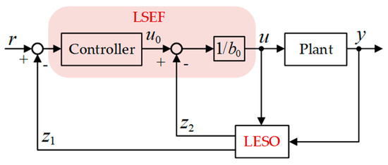
Figure 3.
The structure diagram of the conventional LADRC, where provides a preliminary estimate of the generalized disturbance.
- LESO is mainly used to solve the critical problem of generalized disturbance esti-mation in controlled systems. Furthermore, LESO possesses good adaptability and robustness to a certain range of plants [29].
- The linear state error feedback (LSEF) control law is constructed to compensate for the estimated disturbance by LESO, so that the controlled plant can be reduced to a canonical first-order integral. Meanwhile, a proportional controller responsible for processing the state estimation is integrated into the LSEF to improve dynamic response.
To further enhance the control performance, the cascaded LESO is implemented in the LADRC framework in this paper, which can relatively enhance the estimation accuracy of generalized disturbance. As presented in Figure 4, the residual disturbance part except is estimated by LESO2, denoted as . Then, the generalized disturbance is offset by the joint action of the two estimation signals. Besides, when the dc-link voltage is measurable, it can enter LSEF without being estimated.
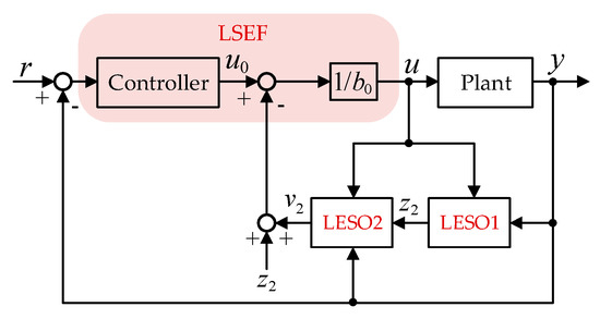
Figure 4.
The structure diagram of the modified LADRC, where is jointly responsible for estimating generalized disturbance.
3.1. Design Procedure of Cascaded LESO
Before establishing the cascaded LESO, the dynamic model (7) was reformulated into a first-order integral form with generalized disturbance,
where and represent the input and output of the plant respectively. , denoted as the generalized disturbance. is the unknown external disturbance. denotes the scaling factor, which transfers part of the system model deviation to the generalized disturbance, and promotes the transformation of the controlled plant to the canonical form.
According to the LESO design principle [20], the states is defined. Therefore, Equation (8) can be re-expressed in the state space model as,
where , , , .
Based on the Equation (9), the conventional second-order LESO can be established as:
where, and reconstruct the states of , and , respectively. The positive gains and are chosen so that the characteristic polynomial (11) is Hurwitz stable [29]:
here, is the tuning parameter of LESO, also known as observer bandwidth.
More importantly, the variable can only be considered a preliminary estimation of the generalized disturbance. The dynamic regulation of depends on the derivative of the first state, usually with faster transients. Now let us assume that the observer bandwidth has been set to a relatively low value, which only guarantees an accurate estimation of the first state . With this parameter limitation, the residual value of the disturbance estimation can be substantial, resulting in the loss of control precision.
To improve the disturbance estimation ability, here is treated as the known part, and a second level LESO2 is constructed to estimate the residual disturbance ,
where variables and have the same properties, and both are responsible for estimating the dynamics of the state . The variable is responsible for supplementing the residual disturbance information. In the same way, the parameters of LESO2 can be determined according to the above pole placement method as:
3.2. Design Procedure of LSEF Control Law
By correctly designing the cascaded LESO and configuring the observer bandwidth , the generalized disturbance in the model (8) can be captured by synthesizing and . However, for disturbance compensation, the following control law is required [29]:
Therefore, the controlled plant is reduced to a canonical first-order integral,
which can be effortlessly regulated by a proportional controller,
indicates proportional gain; is the control quantity; and is the dc-link voltage reference input.
Furthermore, substituting Equation (16) into Equation (15) yields a first-order closed-loop transfer function,
where is referred to as controller bandwidth.
With the cooperation of the cascaded LESO and LSEF control law, the voltage loop control block diagram using the modified LADRC is presented in Figure 5.
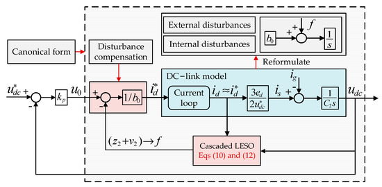
Figure 5.
The voltage loop control block diagram based on modified LADRC, in which the dc link plant with complex nonlinear characteristics is compensated as a canonical first-order pure integral.
3.3. Parameters Tuning
There are three parameters used in the performance test of the improved LADRC: (1) scaling factor ; (2) observer bandwidth ; and (3) controller bandwidth . Generally, the observer bandwidth is determined by seeking a tradeoff between states estimation accuracy and noise immunity, while the controller band-width is chosen according to the required settling time [3].
The detailed parameter tuning process is conducted as follows:
- First, for the plant whose model is known, should be consistent with the model information. In this paper, . If the plant model is complex and difficult to build, a smaller should be selected and gradually increased to test the effect.
- Then, both and incrementally increase from small values until the dc-link voltage can meet the basic control requirements.
- Finally, regulate and in a small range to balance disturbance attenuation and measurement noise rejection.
For engineering applications, a common rule of thumb is to choose [20].
4. Characteristic Analysis of Modified LADRC
To evaluate the control properties of the modified LADRC, -domain transformation was performed on the above expressions, and equivalent transfer functions were derived using linear system theory.
4.1. Evaluation of Disturbance Estimation Performance
By applying the Laplace transform to Equations (10) and (12), the transfer functions of conventional LESO, and cascaded LESO, for estimating generalized disturbances, can be derived respectively:
The Bode plots of Equations (18) and (19) are depicted in Figure 6, with .
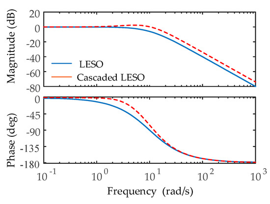
Figure 6.
Comparison of disturbance estimation performance between conventional ESO and cascaded LESO.
It can be seen that the conventional LESO and the cascaded LESO behave like a low-pass filter, and the disturbance composed of low-frequency components can be estimated well. However, the cascaded LESO enables a higher magnitude in the middle and high frequency range, implying stronger disturbance estimation performance. Also, the phase lag in the process of disturbance estimation is also compensated.
In view of Equations (18) and (19), the expressions of LESO and cascaded LESO regarding the disturbance estimation error can be derived as:
According to Equations (20) and (21), it is obvious that both LESO and cascaded LESO can estimate typical step disturbances without generating steady-state errors. However, when the disturbance is a ramp signal with the slope , the conventional LESO inevitably has a steady-state offset of , while the cascaded LESO can still achieve error-free estimation.
Figure 7a depicts the above-mentioned time-domain behavior of LESO and cas-caded LESO, where the generalized disturbance is a ramp signal with , and the observer bandwidth increases from 10 to 50 rad/s, stepped by 10 rad/s. Furthermore, when the observer bandwidth is fixed at 10 rad/s and increases from 10 in steps of 2, the variation curve of the disturbance estimation error is presented in Figure 7b.
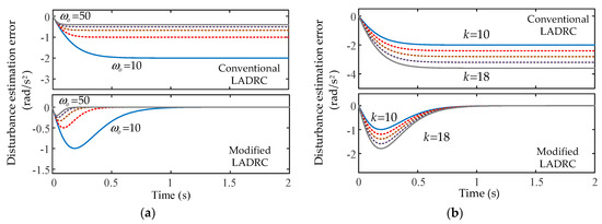
Figure 7.
Estimation error of slope disturbance between conventional LADRC and modified LADRC: (a) Different observer bandwidth ; (b) Different slope .
It can be seen that regardless of the conventional LESO or the cascaded LESO, the observer bandwidth plays a remarkable role in the disturbance estimation process. The larger , the stronger the disturbance estimation performance. Interestingly, when the generalized disturbance contains slope properties, a relatively higher estimation accuracy can be performed by cascaded LESO.
4.2. Evaluation of Disturbance Rejection Performance
For building a controller, the original intention should be to enhance the robustness to undesired disturbances. Therefore, the disturbance rejection performance of the modified LADRC is quantitatively analyzed in this subsection.
By using the Laplace transform to Equations (10), (12), (14) and (16), the modified LADRC-based voltage loop can be simplified to the two-degree-of-freedom (2dof) closed-loop system, as presented in Figure 8.
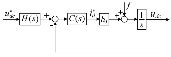
Figure 8.
2dof closed-loop diagram of modified LADRC-based voltage control system.
In the figure, and can be considered as set-point filter and feedback controller respectively, and their expressions are given by,
where:
Therefore, the voltage outer loop control block diagram presented in Figure 5 can be simplified to a standard structure with feedback channel and controlled plant. If the dc-link model is represented by Equation (8), the system output transfer function, concerning the reference input and generalized disturbance, can be readily derived, as follows:
Obviously, if the generalized disturbance is compensated by the control law, Equation (24) is simplified to Equation (17), which means that a fast response without overshoot can be achieved by adjusting .
The Bode plots of the disturbance term are depicted in Figure 9, where the dis-turbance rejection performance of the conventional LADRC and the modified one are comparatively presented. If the frequency is lower than 30 rad/s, the modified LADRC exhibits much smaller magnitude than the conventional one. A stronger disturbance tolerance performance is achieved by modified LADRC. Figure 10 portrays the Bode plots of the modified LADRC disturbance term under different bandwidths. The magnitude is decreased gradually with the increase of or . It means that the higher the determined bandwidth, the stronger the robustness of the grid-connected inverter. However, and cannot be blindly chosen too large, which will cause the overall control performance of the system to deviate from the desired goal.
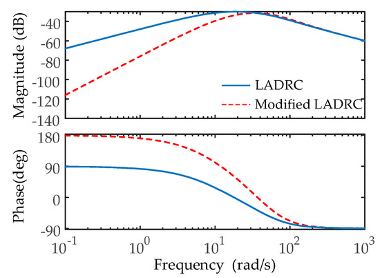
Figure 9.
Comparison of disturbance rejection performance between conventional LADRC and modified one.
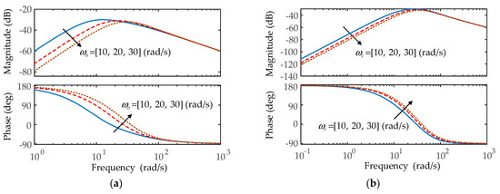
Figure 10.
Disturbance rejection performance under different bandwidths: (a) is fixed at 10 rad/s; (b) is fixed at 10 rad/s.
5. Experimental Results and Discussion
To further verify the correctness of the theoretical analysis, a 3 kW PV grid-connected experimental system was established as shown in Figure 11, which is mainly composed of PV arrays, dc combiner box, inverter cabinet, grid-connected switch and grid emulator. The dc combiner box can prevent line failures by reducing the wiring between the PV array and the inverter. The built-in filter in the grid emulator is responsible for the grid-connected current power quality and harmonic requirements. In addition, the system parameters, used in this study, and the technical indicators of PV arrays under standard test conditions (STC), are listed in Table 1 and Table 2, respectively.
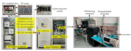
Figure 11.
Experiment platform.

Table 1.
Experimental system parameters.
Table 2.
Technical parameters of PV arrays.
For fair comparison, conventional LADRC and modified LADRC are configured with the same parameters, which are chosen by compromising the states estimation speed, noise sensitivity, and dynamic performance, namely, , . Then, all control algorithms are implemented by using a 32-bit TMS320F28335 digital signal processor.
5.1. Tracking Performance Analysis
To investigate the tracking performance of the two control strategies, a comparative experiment was carried out between the conventional LADRC and the modified one. The time-domain behavior of the dc-link voltage and d-axis current during the startup process are presented in Figure 12 and Figure 13. It can be observed that under the modified LADRC scheme, the voltage overshoot is relatively reduced by about 13 V, and the settling time is shortened by 30 ms. This is because the negative disturbance effect of the modified LADRC is relatively small, forcing the system to behave closer to Equation (17).
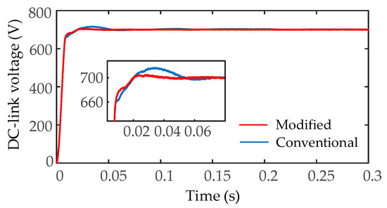
Figure 12.
Comparison of dc-link voltage tracking performance under stationary operating conditions .
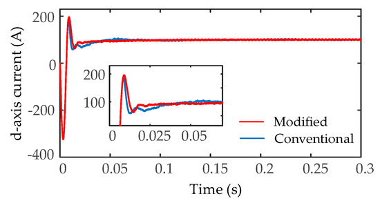
Figure 13.
Comparison of d-axis current tracking performance under stationary operating conditions .
Furthermore, the effective control of the voltage loop can provide a high-quality reference command for the d-axis current. On this basis, the d-axis current based on the modified LADRC can reach a stable operating state within 30 ms, while the conventional LADRC requires 60 ms. Therefore, the modified LADRC has better tracking performance for the set point, which is attributed to the better disturbance estimation ability of the cascaded LESO.
5.2. Robustness Analysis under Solar Irradiance Variations
This test is implemented to analyze and evaluate the robustness of conventional LADRC and modified one under step solar irradiance variations. The characteristics of the PV array determine that its output dc voltage is positively correlated with solar irradiance. As shown in Figure 14, when the solar irradiance drops from 1000 W/m2 to 850 W/m2 at time t = 1.1 s, the modified LADRC reduces the voltage undershoot of 20 V compared with the conventional LADRC, and shortens the recovery time of 20 ms. Similarly, when the solar irradiance is increased from 850 W/m2 to 1000 W/m2 at time t = 1.4 s, the modified LADRC-based voltage control system exhibits a high level of robustness to irradiance disturbances, with a voltage fluctuation of 22 V and a recovery time of 20 ms.
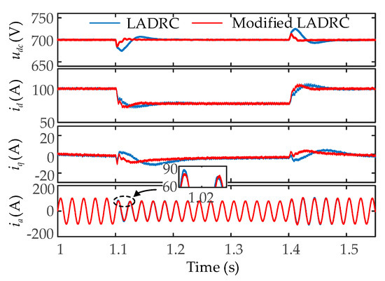
Figure 14.
Robustness comparison under solar radiation variations.
Figure 14 also illustrates the dynamic response of the dq-axis current and the grid phase current . Under modified LADRC, the recovery time of is about 40 ms, while that of conventional LADRC reaches 70 ms. This means that after the irradiance is disturbed, the inverter using the modified LADRC can inject energy into the grid as active power more quickly, achieving unity power factor control. The above analysis can also be verified in the time domain behavior of the grid phase current . In the grid-connected system where the modified LADRC is used in the voltage outer loop, the grid phase current can be restored to a steady-state 30 ms earlier.
5.3. Robustness Analysis under Module Temperature Variations
Figure 15 describes the system response of different control strategies under module temperature variations, where the module temperature rises from to , and returns to the original command again after 300 ms. It can be observed that, when the module temperature variations, both control strategies can guarantee the stability of the dc-link voltage.
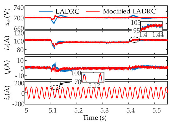
Figure 15.
Robustness comparison under module temperature variations.
Compared with the conventional LADRC, the inverter based on modified LADRC exhibits a maximum voltage change of 12 V and a recovery time of 40 ms, fulfilling the faster dynamic response and stronger robustness. Meanwhile, by observing the time-domain behavior of the dq-axis current, the modified LADRC performs better, in terms of recovery time and transient fluctuations, due to the relatively fast and accurate disturbances estimation, achieved by the cascaded LESO. For the grid phase current , a similar performance is shown in the conventional LADRC and modified one, which can be attributed to the rapidity of the current loop dynamics and the insensitivity of the PV grid-connected system to temperature disturbances.
5.4. Robustness Analysis under Power Grid Voltage Sags
Considering grid codes [12,30], the PV system should support the dc-link voltage stability during different grid disturbances, especially the voltage sags, caused by short-circuit faults. As presented in Figure 16, the PV grid-connected system experimented with symmetrical voltage sag of 10% and 20% during the 500 ms period. As can be observed in this figure, dc-link voltage and other variables gradually return to the operating point of the system before the grid disturbance. However, the PV grid-connected inverter, based on modified LADRC, shows a stronger robustness in dealing with grid voltage sags, which can be described as smaller dc-link voltage fluctuations and shorter transient recovery time, in comparison with the plant employing the conventional LADRC.
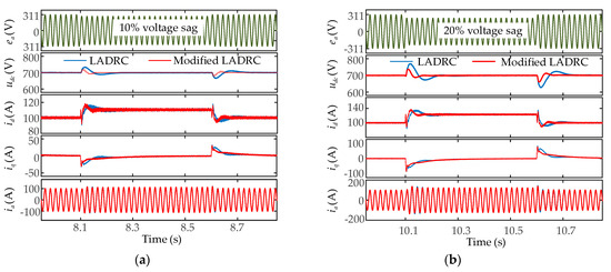
Figure 16.
Robustness comparison under grid voltage sags: (a) 10% voltage sag on grid; (b) 20% voltage sag on grid.
In short, the modified LADRC shows better performance in disturbance rejection, which can be attributed to the superior disturbance estimation ability of cascaded LESO.
6. Conclusions
In this paper, a modified LADRC strategy with cascaded LESO is implemented in the dc link to enhance the dc-link voltage control performance. The second-level LESO can supplement the unestimated residual disturbance information for the first-level LESO, which is conducive to the feedback law for more adequate disturbance compensation. The transient fluctuation problem of the dc link under active power disturbance is analyzed, and the equivalent plant model of the voltage control loop is simplified. From the perspective of time domain and frequency domain analysis, it is demonstrated that the modified LADRC enable stronger disturbance estimation and rejection capabilities than conventional one. Finally, the experimental results prove that the control system, based on the modified LADRC, enables stronger robustness and control dynamics no matter the starting process or under the condition of multi-source disturbance. The reason is that cascaded LESO can achieve faster and more accurate generalized disturbance estimation, thereby reducing the negative effects caused by unpredictable disturbances.
A large number of studies have shown that a class of emerging algorithms such as sliding mode control, fuzzy control and predictive control can also provide similar strong robustness when combined with ESO. ESO is mainly responsible for estimating the defined generalized disturbance. The idea of cascaded LESO, presented in this paper, is also applicable to other nonlinear observers, with the aim of improving the performance of disturbance estimation. Therefore, the combination of cascaded LESO (or ESO), and the above-mentioned control algorithm, deserves more attention from engineers in future work.
Author Contributions
Conceptualization, X.Z. and Q.L.; methodology, Q.L. and W.L.; software, Q.L. and B.X.; validation, Y.M., Q.L. and B.X.; formal analysis, Q.L., X.Z. and B.X.; investigation, W.L. and Y.M.; writing—original draft preparation, Q.L.; writing—review and editing, Q.L.; visualization, X.Z.; supervision, B.X. and Q.L.; funding acquisition, X.Z. All authors have read and agreed to the published version of the manuscript.
Funding
This work was funded by National Natural Science foundation of China (NO. 51877152) and Natural Science Foundation of Tianjin of China (NO. 18JCZDJC97300).
Data Availability Statement
The data presented in this study are available on request from the corresponding author. The data are not publicly available due to private reasons.
Conflicts of Interest
The authors declare no conflict of interest.
References
- Das, N.; Wongsodihardjo, H.; Islam, S. Modeling of multi-junction photovoltaic cell using MATLAB/Simulink to improve the conversion efficiency. Renew. Energy 2015, 74, 917–924. [Google Scholar] [CrossRef]
- Kumar, S.; Abu-Siada, A.; Das, N.; Islam, S. Toward a Substation Automation System Based on IEC 61850. Electronics 2021, 10, 310. [Google Scholar] [CrossRef]
- Benrabah, A.; Xu, D.G.; Gao, Z.Q. Active Disturbance Rejection Control of LCL-Filtered Grid-Connected Inverter Using Pade Approximation. IEEE Trans. Ind. Appl. 2018, 54, 6179–6189. [Google Scholar] [CrossRef]
- Netzahuatl-Huerta, E.; Hernandez-Gonzalez, L.; Cortes, D.; Ramirez-Hernandez, J. Design and Implementation Procedure of a High-Gain Three-Input Step-Up 1 kW Converter. Electronics 2021, 10, 625. [Google Scholar] [CrossRef]
- Chinnappan, R.; Logamani, P.; Ramasubbu, R. Fixed frequency integral sliding-mode current-controlled MPPT boost converter for two-stage PV generation system. IET Circ. Devices Syst. 2019, 13, 793–805. [Google Scholar] [CrossRef]
- Lu, J.H.; Golestan, S.; Savaghebi, M.; Vasquez, J.C.; Guerrero, J.M.; Marzabal, A. An Enhanced State Observer for DC-Link Voltage Control of Three-Phase AC/DC Converters. IEEE Trans. Power Electron. 2018, 33, 936–942. [Google Scholar] [CrossRef]
- Chowdhury, M.A. Dual-loop H-infinity controller design for a grid-connected single-phase photovoltaic system. Sol. Energy 2016, 139, 640–649. [Google Scholar] [CrossRef]
- Blaabjerg, F.; Teodorescu, R.; Liserre, M.; Timbus, A.V. Overview of control and grid synchronization for distributed power generation systems. IEEE Trans. Ind. Electron. 2006, 53, 1398–1409. [Google Scholar] [CrossRef]
- Al-Hilfi, H.A.H.; Abu-Siada, A.; Shahnia, F. Combined ANFIS-Wavelet Technique to Improve the Estimation Accuracy of the Power Output of Neighboring PV Systems during Cloud Events. Energies 2020, 13, 1613. [Google Scholar] [CrossRef]
- Al-Hilfi, H.A.H.; Abu-Siada, A.; Shahnia, F. Estimating Generated Power of Photovoltaic Systems During Cloudy Days Using Gene Expression Programming. IEEE J. Photovolt. 2021, 11, 185–194. [Google Scholar] [CrossRef]
- Singh, B.N.; Jain, P.; Joos, G. Three-Phase AC/DC Regulated Power Supplies: A Comparative Evaluation of Different Topologies. In Proceedings of the APEC 2000. Fifteenth Annual IEEE Applied Power Electronics Conference and Exposition (Cat. No.00CH37058), New Orleans, LA, USA, 6–10 February 2000; Volume 1, pp. 513–518. [Google Scholar]
- Ding, G.Q.; Gao, F.; Tian, H.; Ma, C.; Chen, M.X.; He, G.Q.; Liu, Y.L. Adaptive DC-Link Voltage Control of Two-Stage Photovoltaic Inverter During Low Voltage Ride-Through Operation. IEEE Trans. Power Electron. 2016, 31, 4182–4194. [Google Scholar] [CrossRef]
- Hao, X.; Yang, X.; Liu, T.; Huang, L.; Chen, W.J. A Sliding-Mode Controller With Multiresonant Sliding Surface for Single-Phase Grid-Connected VSI With an LCL Filter. IEEE Trans. Power Electron. 2013, 28, 2259–2268. [Google Scholar] [CrossRef]
- Leitner, S.; Yazdanian, M.; Ziaeinejad, S.; Mehrizi-Sani, A.; Muetze, A. Internal Model-Based Active Resonance Damping Current Control of a Grid-Connected Voltage-Sourced Converter With an LCL Filter. IEEE Trans. Power Syst. 2018, 33, 6025–6036. [Google Scholar] [CrossRef]
- El-Sousy, F.F.M. Hybrid H-infinity-Based Wavelet-Neural-Network Tracking Control for Permanent-Magnet Synchronous Motor Servo Drives. IEEE Trans. Ind. Electron. 2010, 57, 3157–3166. [Google Scholar] [CrossRef]
- Kim, S.C.; Nguyen, T.H.; Lee, D.C.; Lee, K.B.; Kim, J.M. Fault Tolerant Control of DC-Link Voltage Sensor for Three-Phase AC/DC/AC PWM Converters. J. Power Electron. 2014, 14, 695–703. [Google Scholar] [CrossRef]
- Wang, C.S.; Li, X.L.; Guo, L.; Li, Y.W. A Nonlinear-Disturbance-Observer-Based DC-Bus Voltage Control for a Hybrid AC/DC Microgrid. IEEE Trans. Power Electron. 2014, 29, 6162–6177. [Google Scholar] [CrossRef]
- Liu, J.X.; Vazquez, S.; Wu, L.G.; Marquez, A.; Gao, H.J.; Franquelo, L.G. Extended State Observer-Based Sliding-Mode Control for Three-Phase Power Converters. IEEE Trans. Ind. Electron. 2017, 64, 22–31. [Google Scholar] [CrossRef]
- Han, J.Q. From PID to Active Disturbance Rejection Control. IEEE Trans. Ind. Electron. 2009, 56, 900–906. [Google Scholar] [CrossRef]
- Zhiqiang, G. Scaling and bandwidth-parameterization based controller tuning. In Proceedings of the 2003 American Control Conference, Denver, CO, USA, 4–6 June 2003; pp. 4989–4996. [Google Scholar]
- Xue, W.C.; Huang, Y. Performance analysis of active disturbance rejection tracking control for a class of uncertain LTI systems. ISA Trans. 2015, 58, 133–154. [Google Scholar] [CrossRef]
- Li, H.; Liu, X.X.; Lu, J.W. Research on Linear Active Disturbance Rejection Control in DC/DC Boost Converter. Electronics 2019, 8, 1249. [Google Scholar] [CrossRef]
- Liu, C.Q.; Luo, G.Z.; Duan, X.L.; Chen, Z.; Zhang, Z.L.; Qiu, C. Adaptive LADRC-Based Disturbance Rejection Method for Electromechanical Servo System. IEEE Trans. Ind. Appl. 2020, 56, 876–889. [Google Scholar] [CrossRef]
- Hasan, M.M.; Abu-Siada, A.; Dahidah, M.S.A. A Three-Phase Symmetrical DC-Link Multilevel Inverter With Reduced Number of DC Sources. IEEE Trans. Power Electron. 2018, 33, 8331–8340. [Google Scholar] [CrossRef]
- Fu, X.Q.; Fu, Q.; Tang, W.W. Grid connection technique based on mu theory for a two-stage PV structure. IET Power Electron. 2019, 12, 1545–1553. [Google Scholar] [CrossRef]
- Gu, B.G.; Nam, K. A DC-link capacitor minimization method through direct capacitor current control. IEEE Trans. Ind. Appl. 2006, 42, 573–581. [Google Scholar]
- Aghanoori, N.; Masoum, M.A.S.; Abu-Siada, A.; Islam, S. Enhancement of microgrid operation by considering the cascaded impact of communication delay on system stability and power management. Int. J. Electr. Power Energy Syst. 2020, 120, 105964. [Google Scholar] [CrossRef]
- Wang, R.Z.; Li, X.M.; Liu, Y.F.; Ahemd, Q.; Yang, Y.L.; Feng, C.Y.; Ma, X.Z. Variable Sampling Rate based Active Disturbance Control for a Marine Diesel Engine. Electronics 2019, 8, 370. [Google Scholar] [CrossRef]
- Zhou, R.; Tan, W. Analysis and Tuning of General Linear Active Disturbance Rejection Controllers. IEEE Trans. Ind. Electron. 2019, 66, 5497–5507. [Google Scholar] [CrossRef]
- Abu-Siada, A.; Islam, S. Application of SMES Unit in Improving the Performance of an AC/DC Power System. IEEE Trans. Sustain. Energy 2011, 2, 109–121. [Google Scholar] [CrossRef]


Publisher’s Note: MDPI stays neutral with regard to jurisdictional claims in published maps and institutional affiliations. |
© 2021 by the authors. Licensee MDPI, Basel, Switzerland. This article is an open access article distributed under the terms and conditions of the Creative Commons Attribution (CC BY) license (https://creativecommons.org/licenses/by/4.0/).