Article

Experimental Study of the Free Space Optics Communication System Operating in the 8–12 µm Spectral Range

by
Magdalena Garlinska
1,*,
Agnieszka Pregowska
2,*,
Izabela Gutowska
3,
Magdalena Osial
4 and
Janusz Szczepanski
2
1
National Center for Research and Development, 00 695 Warsaw, Poland
2
Institute of Fundamental Technological Research, Polish Academy of Sciences, 02 106 Warsaw, Poland
3
100 Radiation Center, School of Nuclear Science and Engineering, Oregon State University, Corvallis, OR 97331, USA
4
Faculty of Chemistry, University of Warsaw, 02 093 Warsaw, Poland
*
Authors to whom correspondence should be addressed.
Electronics 2021, 10(8), 875; https://doi.org/10.3390/electronics10080875
Submission received: 24 March 2021 / Revised: 2 April 2021 / Accepted: 4 April 2021 / Published: 7 April 2021
(This article belongs to the Section Microwave and Wireless Communications)

Abstract

:
(1) Background: Free space optics communication (FSO) has improved wireless communication and data transfer thanks to high bandwidth, low power consumption, energy efficiency, a high transfer capacity, and a wide applicability field. The FSO systems also have their limitations, including weather conditions and obstacles in the way of transmission. (2) Methods: This research assesses the atmospheric conditions’ influence on the intensity of received radiation, both experimentally and theoretically. The construction of a laboratory test stand of the FSO system, which is operating in the third-atmosphere transmission window (8–12 µm), is proposed. Next, considering different atmospheric conditions, the experimental validation was conducted, both in a laboratory and real conditions. (3) Results: The measurements were carried out for two optical links working with wavelengths of 1.5 µm and 10 µm. It was found that optical radiation with a wavelength of about 10 µm is characterized by better transmission properties in the case of limited visibility (e.g., light rain and fogs) than in the case of near-infrared waves. The same conclusion was found in analytical investigations. (4) Conclusions: The results obtained show that optical radiation with a wavelength of about 10 µm in limited visibility is characterized by better transmission properties than near-infrared waves. This demonstrates the validity of designing FSO links operating in the range 8–12 µm band, e.g., based on quantum cascade lasers and HgCdTe photodiodes.

1. Introduction

Free space optics communication (FSO) is data transmission technology based on light propagation in free space. It takes full advantage of linking high-speed connections with energy efficiency; compact size; the low costs of installation, maintenance, and operation to enhance the communication system’s accessibility [1,2]. Moreover, it also provides unprecedented levels of data transmission security [3]. The main advantage of FSOs is their wide application field that includes outdoor wireless access, backhaul, fiber backup, last mile [4,5], bridging Wide Area Network (WAN) [6], and military access [7]. Several factors can significantly reduce the transmission efficiency, in particular, physical obstructions, rain [8], temperature fluctuations in different air layers [9], geometric losses [10], absorption [11], atmospheric turbulence [12,13,14], and atmosphere attenuation and scattering [15]. In commercial FSO communication systems, strictly defined wavelengths of approximately 0.8 µm and 1.5 µm are used [16,17]. Their selection is dependent on the characteristics of the atmosphere’s attenuation and the availability of sources and detectors of optical radiation [18].
The development of quantum cascade (QC) lasers operating in the long-wave infrared radiation and highly sensitive mercury cadmium telluride (MCT) detectors provided new possibilities for FSO links [19,20]. It has become possible to develop an FSO link operating at wavelengths 8–12 µm where there is less attenuation caused by mists with fine aerosol particles than in the case of commercially available links. These links are also safe for eyesight [21]. The conducted analyses show that for the construction of an optical link in open space, characterized by lower attenuation in hazy conditions than currently existing ones, QC lasers and MCT photodiode operating in the spectral range of 8–12 µm can be used [22,23,24].
Currently, no optical links operating in this wavelength range are available on the market. Until recently, one of the most significant barriers to their development was the lack of appropriate radiation sources.
Due to the development of QC lasers [25,26], it was possible to initiate work on the constructing FSO links operating in the 8–12 µm wavelength range. However, the development of such a link was coupled with the need to solve several design problems, both for transmitters and receivers of optical radiation. To obtain a long range of the link, with a low error rate and high data transmission speed, it was necessary to select the optimal operating conditions for the QC laser and minimize the noise of the photoreceiver’s input stage, with the possibly wide transmission band.
In this paper, the theoretical and experimental relationship between atmospheric conditions and the intensity of received radiation in the FSO links was analyzed. Two optical links working with wavelengths 1.5 µm and 10 µm were analyzed. The transmission quality was characterized by the realized bit error rate (BER) [27]. It was found that improved transmission properties in the case of limited visibility were obtained for a wavelength of about 10 µm, compared to the near-infrared waves. Analogous situations related to the selection/determination of appropriate parameters of the sources generating signals being sent through noisy transmission channels to improve the transmission efficiency also occur in classic transmission channels [28,29,30,31,32,33].
The paper is organized as follows: In Section 2, the construction of the detection and transmitter modules is described, respectively. Section 3 shows the laboratory test stand and experimental results and presents the experimental results in real conditions. Section 4 contains the discussion and conclusions.

2. Materials and Methods

In Figure 1, the detection module, which is used in the proposed FSO link, is presented. It is a modified version of the VPAC series of modules by VIGO System S.A.
The standard housing of such a module includes an infrared radiation detector, a four-stage thermoelectric cooler (TEC) with a temperature sensor, a broadband preamplifier, electromagnetic noise filters (EMIs), and a miniature fan dissipating the heat emitted by the cooler. Additionally, this equipment includes a TEC controller and a DC power supply. In Figure 2, a block diagram of this module is presented.
The current signal obtained from the HgCdTe photodiode is read by a wideband (about 1 GHz) trans-impedance amplifier. This amplifier also provides a constant reverse power supply to the detector with a voltage of 200 mV. This creates the conditions for obtaining the maximum signal-to-noise ratio over a wide frequency range. Table 1 presents the most important parameters of this module, optimized for a wavelength of 10 μm. More detailed descriptions and experimental research on detection modules, shown in Figure 2, are presented in References [23,24].
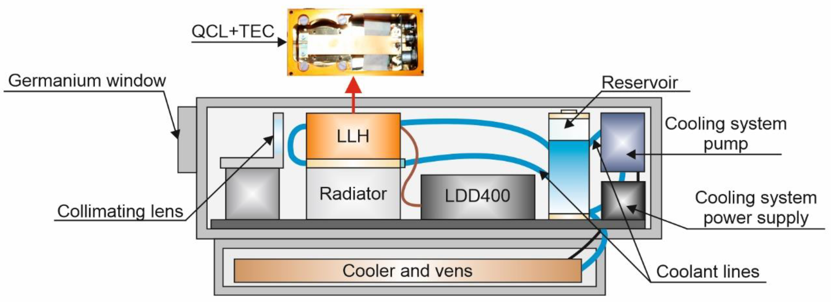
In the transmitter module, a cascade laser from Alpes Lasers was used [34]. The laser control system consists of a laboratory laser housing (LLH) in which the laser was placed on a thermoelectric cooler, a laser diode driver (LDD 400), and a thermoelectric cooler controller (TCU 200). A window made of zinc selenide (ZnSe) with a diameter of 11 mm, which is transparent to radiation with a wavelength of 3.5 to 12 µm, was installed in the head.
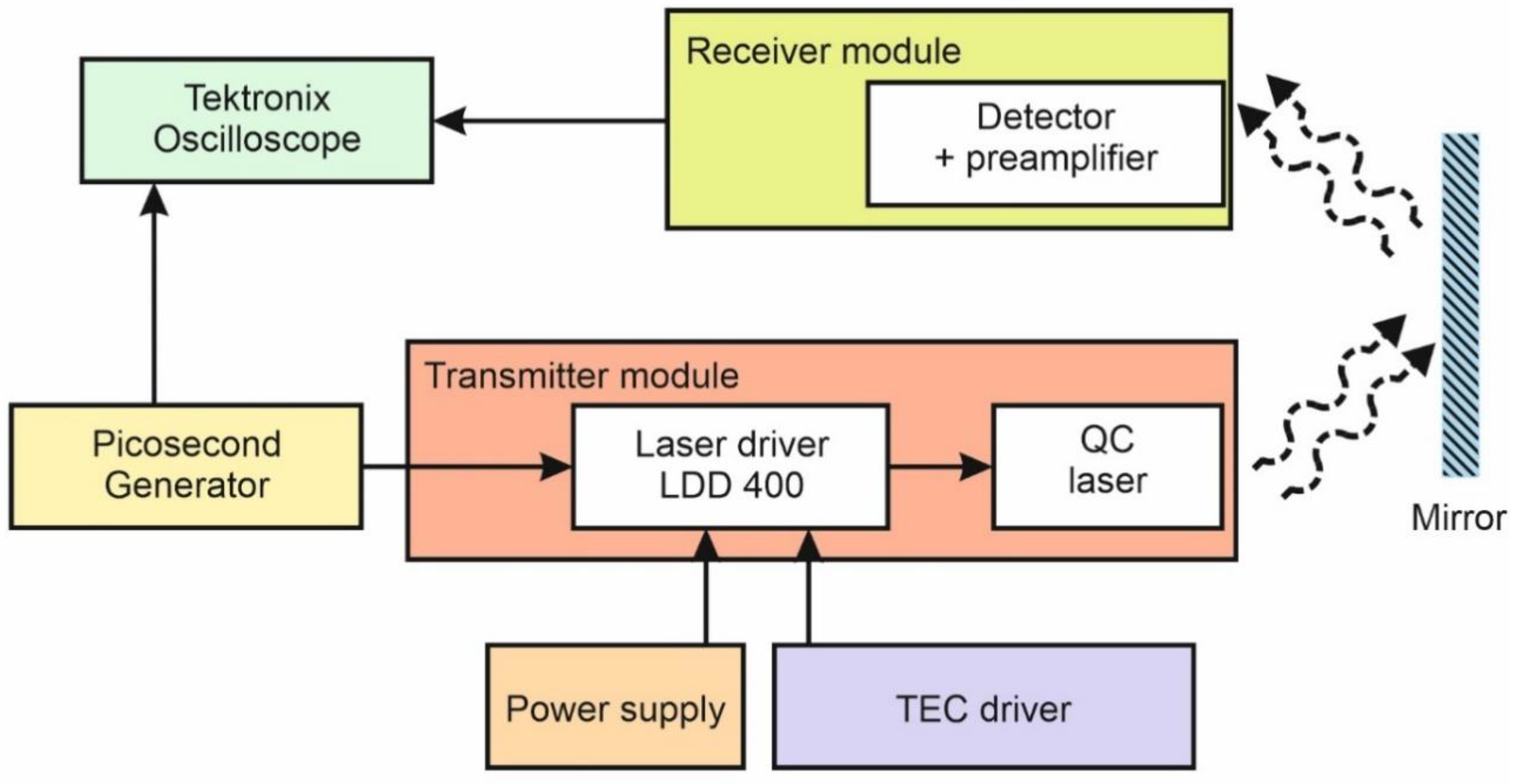
The LDD 400 module was used to control the laser. It has an output to monitor the current flowing through the laser structure. The LLH laser head was connected to the LDD 400 system with a low-impedance tape. An external generator was required to control the LDD 400 system. A TCU 200 controller was used to regulate the operating temperature of the QC laser. The temperature was measured by a PT100 temperature sensor built into the head. The temperature control range is from −40 to +80 °C. The built-in display allowed us to read the set and current temperature with a resolution of 0.1 °C. The construction of the laser head also allowed the use of additional cooling using water circulation. A TPG 200 generator was used to generate the laser control pulses. This generator enables laser control via the LDD 400 system. It allows the generation of pulses with a duration of up to 200 ns at a frequency of 10 kHz to 5 MHz. It is also equipped with a trigger input for synchronization of the generated pulses with an external signal and with two control outputs according to the TTL (Transistor-Transistor-Logic) standard with an impedance of 50 Ω, enabling to obtain the rise and fall times of the control pulses below 10 ns. An additional water-cooling system for the laser head was used for research purposes. It consisted of an electric water pump, an expansion tank, a radiator with fans, and coolant lines.
Figure 3 shows a diagram of the FSO system transmitter module. This module consisted of an optical system, a laser head with a cascade laser, a laser power supply, a beam collimating lens, and a water-cooling system. The optical system of the transmitting module used a single lens with a diameter of 25 mm, placed at a distance of 25 mm from the LLH head window in the optical axis of the laser.
The results of laboratory tests of transmitter modules, which are analyzed in the proposed FSO system, are presented in References [22,35,36]. Experimental studies were conducted for the QCL laser to determine the optimum operational parameters of its work, taking into account the possibility of its use in the FSO link. The researches included: measuring the characteristics of the average optical power changes as a function of control voltage, the current flowing through the laser structure and the temperature of the laser, and the designation of the spectral characteristics. The study has shown that the laser form Alpes Lasers can be successfully used in the FSO link [22].

3. Results

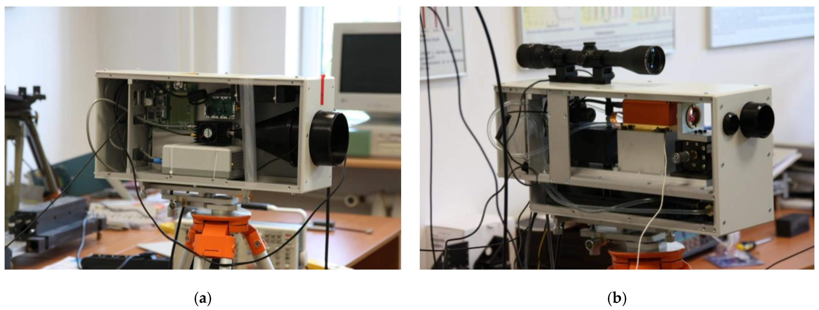
In the next step, the designed transmitter and receiver modules were used in the research laboratory setup as presented in Figure 4. They were located next to each other and facing the mirror on the opposite side of the laboratory. The optical path was about 70 m. The scheme of the laboratory test stand is presented in Figure 5.
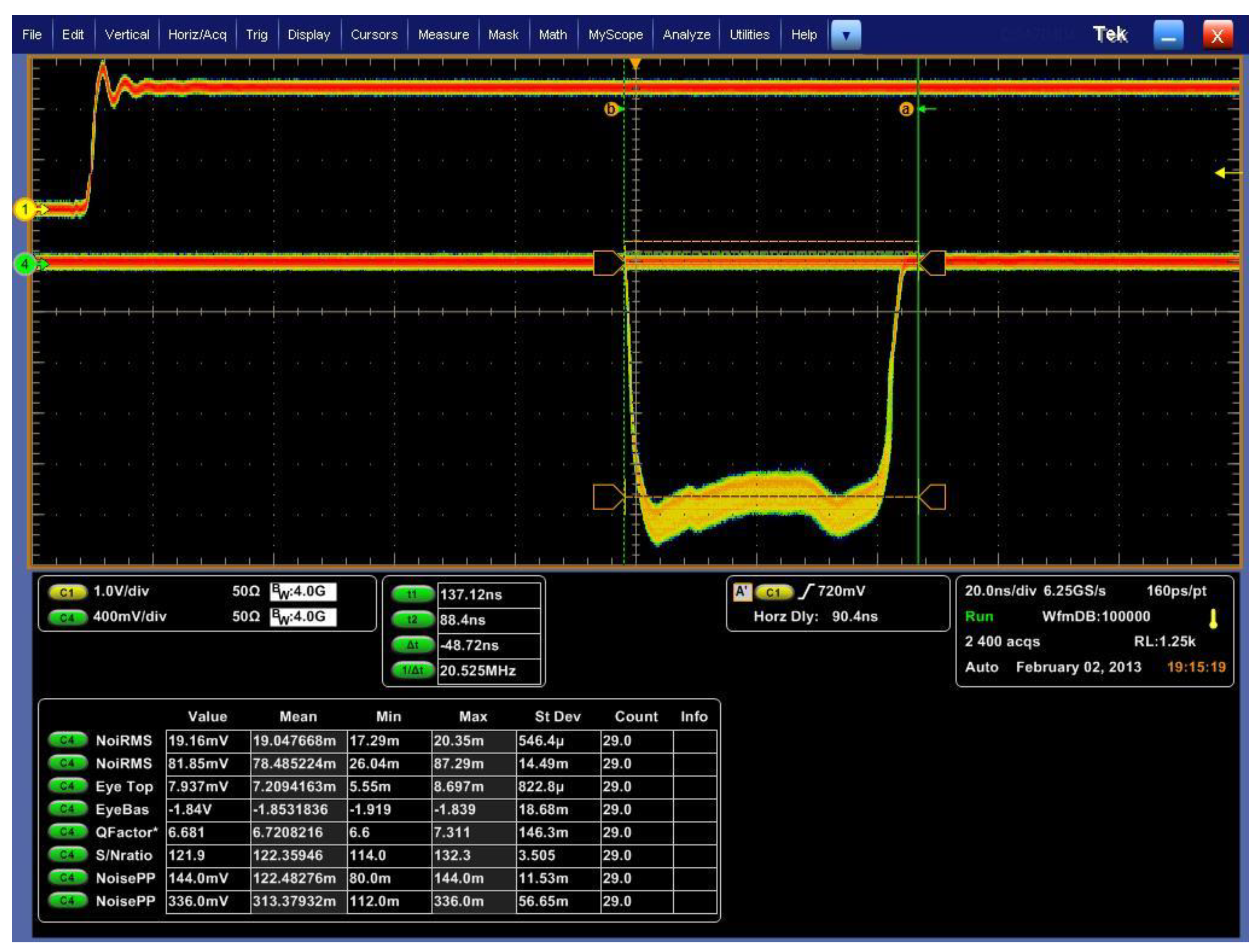
The Tektronix DSA 70404 analyzer software-Jitter and Eye Diagram Analysis Tools was used to analyze the effect of the frequency and duration of laser pulses on the BER [27,37]. This software allowed for the obtention of an image resulting from the overlapping of successive pulses with a color determinant of the frequency of their occurrence.
To verify the correctness of the adopted measurement method, a sequence of 15000 pseudo-random pulses in the return to zero (RZ) code with an amplitude of 2.5 V, frequency of 1 MHz and duration of 100 ns was generated using the Picosecond 12000 generator. The pulse sequence from the generator was visualized by storing the recorded waveforms in the internal memory (WfmDB function) with simultaneous imaging (Infinity Persistance function) on the oscilloscope. Then the following parameters were measured: signal mean value at logical levels “0” and “1” (EyeTop and EyeBase), Q factor, signal-to-noise ratio, RMS (Root Mean Square) noise value at logical levels “0” and “1” (NoiseRMStop and NoiseRMSbase). The measurements were carried out with the limitation of the measurement area, with the use of cursors, to the pulse duration. Figure 6 shows an example of the oscillogram obtained during the measurements. The method of measuring individual signal parameters was also verified.
It was found that the RMS noise values at logical levels “0” and “1 were determined in half of the pulse duration, while the signal mean values at logical levels “0” and “1” were determined and averaged over the range delimited by the cursors. From the presented oscillogram, the values of the Q and S/N coefficients were read. They are 4.918 and 91.05, respectively. The data assessment showed that the measurement of the Q parameter with the gating turned on was consistent with the value determined from the formula [37]:
Q = E y e T o p E y e B a s e N o i s e R M S t o p + N o i s e R M S b a s e
The individual components of this formula were read from the waveform screen.
A Picosecond 12,000 generator was used to test the effect of the laser pulse repetition frequency, the pulse cycle factor, and the laser operating temperature on the BER value. Parameters of the generated pulses are presented in Table 2. The generator used for the research made it possible to create a pseudo-random sequence of bits stored in the device’s internal memory. Pulse waveforms with a given frequency, duration, and amplitude were obtained at the generator output according to the previously created pseudo-random sequence.
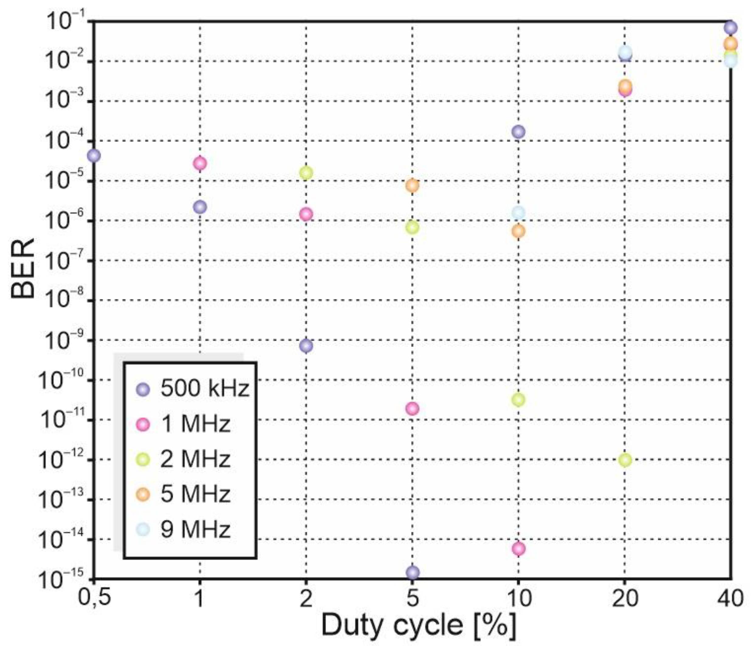
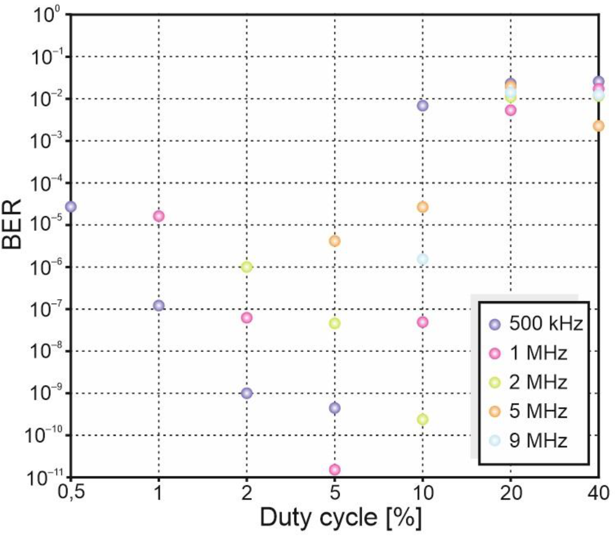
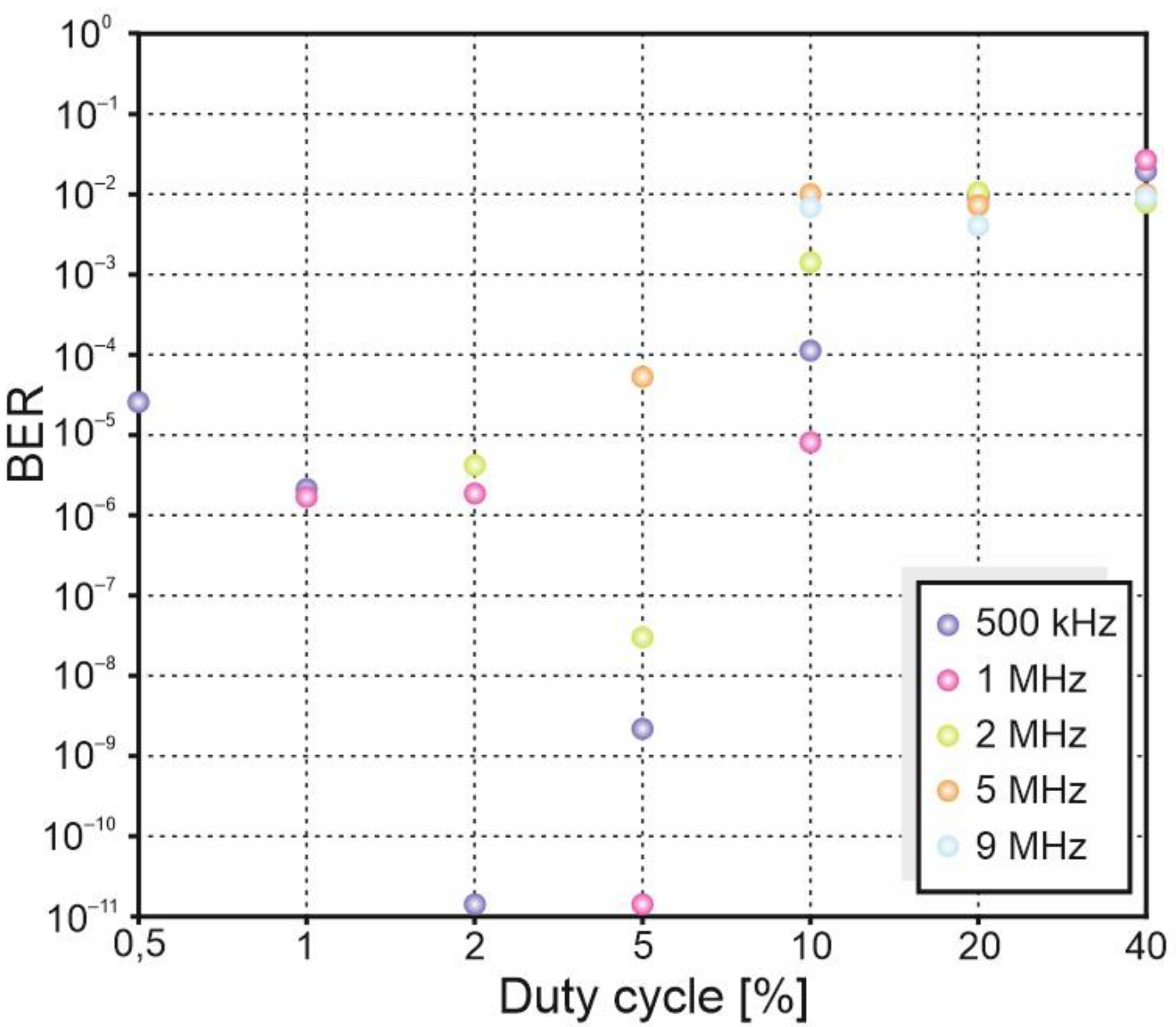
In Figure 7, Figure 8 and Figure 9, the determined BER dependencies for different values of the pulse duty cycles, frequency values, and laser operating temperatures are presented.
The conducted research shows that with the increase in the pulse duty factor, the BER value initially decreases and then increases. The lower the laser operating temperature, the lower the BER value for a given frequency. For the laser operating temperature of −10 °C, and the frequencies of 500 kHz, 1 MHz, and 2 MHz, the lowest BER value was obtained for pulses of 100 ns duration. For the temperature of −10 °C, the lowest BER, amounting to 10−15, was obtained for the frequency of 500 kHz, while for 2 MHz the BER was obtained at the level of 10−12. On the other hand, for a temperature of 0 °C, and frequencies of 500 kHz, 1 MHz, and 2 MHz, the lowest BER was obtained for pulses with a duration of about 40 ns. For the laser operating temperature of 20 °C, the best transmission quality was obtained for the pulse duration of 25 ns.
As the laser operating temperature increased, the minimum BER value was obtained for shorter pulse durations. The heating of the laser structure during the long-duration generation causes their overmodulation and an increase in noise at the logical “1” level.
With the increase in the laser operating temperature, an increase in the fluctuation of the amplitude of the pulses was also observed. This is due to the heating of the QC structure during current flow as well as the change in operating conditions due to the limited efficiency of the cooling system. Along with the increase of the pulse duration, increasing the laser operating temperature causes a further decrease in amplitude and an increase in the noise value. The choice of the link operating point is a compromise between the required amplitude, bandwidth, and noise value.
For longer pulses, a several-fold decrease in the S/N value resulting from thermal effects occurring in the laser structure was observed. The use of an additional system stabilizing the temperature of the cooling medium, e.g., at 0 °C, would allow for more stable laser operation at even lower temperatures. However, its use will increase the size of the link, and at the same time will make it difficult to use it outside the laboratory.
Based on the conducted laboratory tests it was decided that the field tests would be carried out for the laser operating temperature of −10 °C, the frequency of 2 MHz, and the pulse duration of 100 ns.
The experimental validation of the proposed FSO system in the real conditions is conducted for two measurement tracks. The first one with the designed link, and the second one with a laser generating radiation with a wavelength of 1.5 µm. The third path with laser generating radiation with a wavelength of 550 nm was used to determine visibility. The air temperature was measured with a digital thermometer and the relative humidity with a hygrometer. A diagram of the research stand for examining the influence of atmospheric conditions on the link operation is presented in Figure 10.
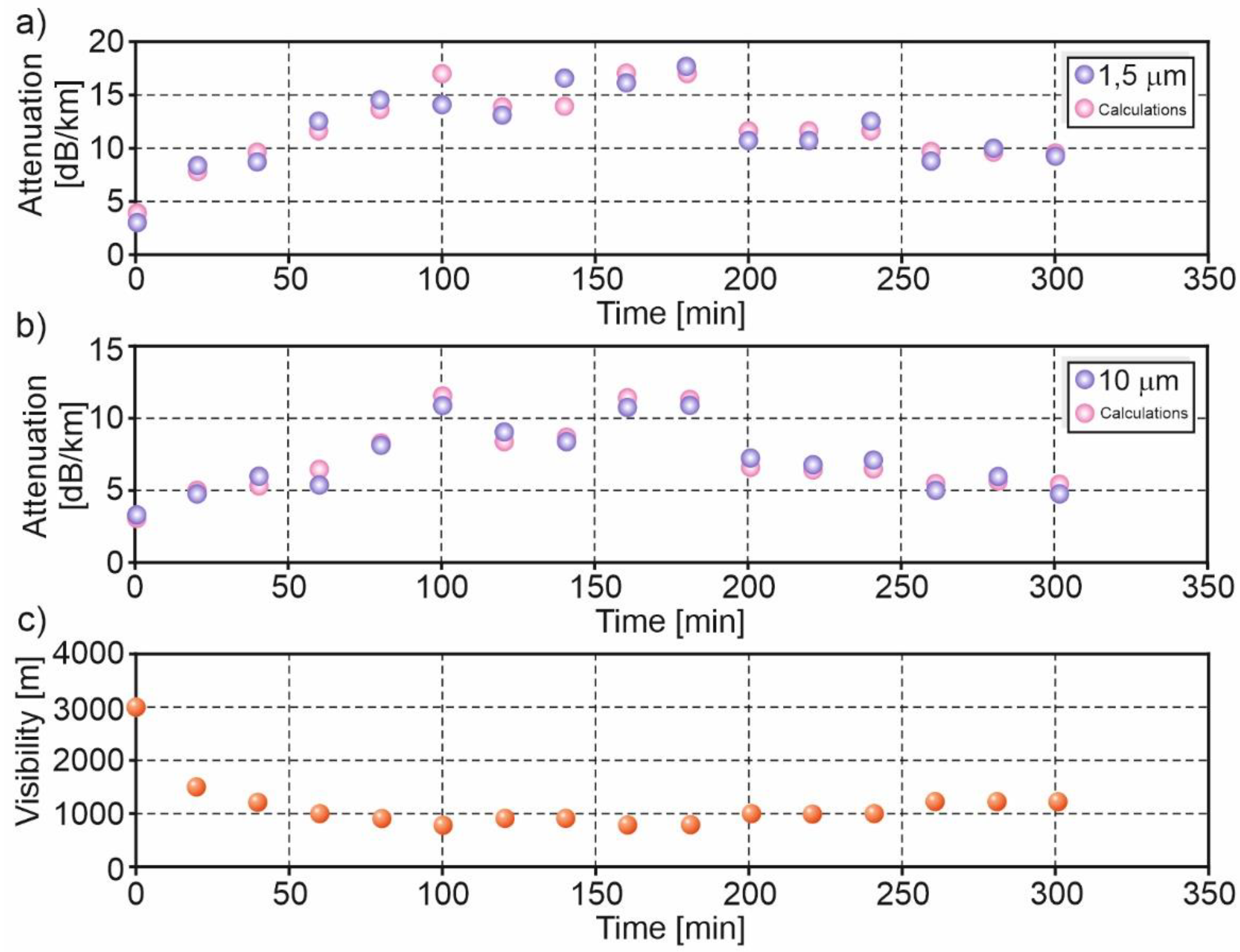
The conditions under which the experiment was carried out are presented in Figure 11. The link was about 80 m, crossing the Military University of Technology from side to side. Figure 12 shows the results obtained during the tests carried out in light haze conditions are presented: the air temperature was 10 °C, and the relative humidity was 100%.
The amplitude of the signals at the output of the photoreceivers was measured every 20 min. Based on the obtained measurement results, the atmospheric attenuation of radiation with a wavelength of 1.5 µm and 10 µm was determined. The results obtained were compared with the analytical calculations carried out using the MathCAD software presented in the previous paper [38]. These calculations are based mainly on using the formula combining the transmission coefficient with the propagation length and the extinction coefficient [39] and using the relationship between absolute humidity and water sedimentation indicator [40]. The performed calculations showed that the currently used FSO systems with lasers generating radiation of about 800–900 nm and 1.5 µm were sensitive to bad weather conditions, particularly fog. For the visibility of 1 km, which corresponds to light fog, the link operating with a wavelength of 10 μm was characterized by the best range parameters. Therefore, the radiation with a wavelength of 10 µm, therefore, has better transmission properties in the case of limited visibility (e.g., light rain and fog) than near-infrared waves. For visibility below 600 m (e.g., heavy rain), the obtained attenuation, taking into account the scattering effect, is comparable for the three analyzed wavelengths. This means that in difficult weather conditions, for significantly reduced visibility, all systems will experience problems with ensuring good communication quality, and there may even be problems with establishing a connection. On the other hand, for the visibility of 1 km (fog), the attenuation coefficient of the atmosphere takes the values of 13.43 dB, 10.11 dB, and 3.98 dB for the wavelengths of 880 nm, 1.5 µm, and 10 µm, respectively. Also, radiation with a wavelength of 10 µm is less sensitive to turbulence in the atmosphere compared to short-wave radiation. In the case of strong turbulence, for the distance between the transmitter and the receiver of 1 km, the radiation’s attenuation with a length of 880 nm and 1550 nm takes similar values, i.e., about 0.9 dB. However, radiation with a wavelength of 10 µm will be attenuated by 0.75 dB.
The ambient temperature is one of the critical factors influencing the quality of the link’s operation, the thermal radiation from buildings and the environment produces a significant signal that must be removed if possible. Such links should not be placed near air conditioners or pipes with hot liquids, as well as when the facade of the building is made of metal, as its heating may create additional turbulence.
It turned out that, in the case of good visibility (3000 m), radiation with a wavelength of 10 µm was characterized by attenuation similar to radiation with a wavelength of 1.5 µm. As visibility decreases, the attenuation for both wavelengths increased. On the other hand, for the visibility of 800 m and a slight haze, the attenuation of radiation in the far-infrared range was approximately 10 dB/km, and near-infrared approximately15 dB/km. The obtained analytical results were comparable to the experimental data as presented in Figure 12.

4. Discussion

In this paper, an FSO system that operated in the third-atmosphere transmission window (8–12 µm) was presented. According to our studies [35,36,38], in the case of worse weather conditions (moderate fog or mist), the designed link can effectively sustain the continuity of the connection. In Reference [41], the dependence on transmission efficiency and the position of the turbulence source within the chamber was presented. In Reference [42], the FSO system analysis in tropical weather was investigated, while the test in the area surrounding the city with a Mediterranean climate is shown in Reference [43]. In Reference [44], FSO efficiency in the maritime environment was investigated. A mathematical model of the received signal strength, taking into account a single-point measurement system for atmospheric parameters, was proposed.
On the other hand, in Reference [45] the influence of spatial and temporal characteristics of atmospheric turbulence was analyzed. It turned out that temporal characteristics were slightly stronger than spatial ones. To guarantee good communication quality with increasing spatial characteristics, it is necessary to provide a wide bandwidth.
The results obtained in this work indicate that the proposed FSO link works as desired both in the laboratory and in real conditions. The data from theoretical calculations were compared with the experimental results taking into account the atmospheric conditions. It turned out that similar attenuation values for individual wavelengths were obtained. Analytical calculations have shown that the FSO link operating at a wavelength of 10 μm, under the conditions of visibility from 0.8 to 1.0 km, relative humidity of 70% and at a temperature of 0 °C, for a distance between the transmitter and receiver of about 2 km will have a larger optical power reserve than the system operating at 1.55 µm wavelength, despite that, the assumed transmitter power for 10 µm wavelength was lower than for a 1.55 µm transmitter. This means that it is possible to reduce the radiation power generated by the laser operating in the third-generation link to reduce operating costs and extend its operating time while maintaining link range for commercially available systems. Laboratory and field tests confirmed the results of analytical analyzes.
To improve the links turbulence problems may be reduced. Many research activities on beam control and tracking techniques for mitigating deleterious effects of angle-of-arrival fluctuation and pointing error on the performance of free-space optical communications are available. To increase the reliability of the system, in conditions where scintillation or turbulence of the atmosphere can cause signal fading, automatic resumption of packet transmission, appropriate modulation types, multi-beam systems or adaptive optics systems are also used.
If the weather conditions are bad during the links operation (i.e., there is dense snow or a rainstorm), the FSO operating at a wavelength of 10 µm will be able to provide a range similar to commercial systems. Similarly, in a situation of good visibility, i.e., above 2000 m. It is worth emphasizing that the designed link, apart from the fact that it provides better quality of transmission in fog or rain conditions, is also safer for eyesight. Thus, it is reasonable to use radiation sources in the far-infrared range in FSO systems.
To summarize, the results showed that optical radiation with a wavelength of approximately 10 µm was characterized by better transmission properties in the case of limited visibility (e.g., light rain and fogs) than in the case of near-infrared waves.

Author Contributions

Conceptualization, M.G., A.P., and J.S.; writing—original draft preparation, M.G., A.P., I.G., M.O.; writing—review and editing A.P., M.G., I.G., and J.S.; visualization, M.G. All authors have read and agreed to the published version of the manuscript.

Funding

This research received no external funding.

Acknowledgments

The research presented in this work was carried out as part of the research for Magdalena Garlińska’s doctoral dissertation on the equipment purchased as part of the O R00 0086 06 project.

Conflicts of Interest

The authors declare no conflict of interest.

References

  1. Kumar, N.; Kumar Rana, A. Impact of various parameters on the performance of free space optics communication system. Optik 2013, 124, 5774–5776. [Google Scholar] [CrossRef]
  2. Majumdar, A.K.; Ricklin, J.C. Free-Space Laser Communications: Principles and Advances 5–10; Springer: Berlin/Heidelberg, Germany, 2010. [Google Scholar]
  3. Vigneshwaran, S.; Muthumani, I.; Raja, A.S. Investigations on Free Space Optics Communication System. In Proceedings of the International Conference on Information Communication & Embedded Systems (ICICES ‘13) IEEE, Chennai, India, 21–22 February 2013; pp. 819–824. [Google Scholar]
  4. Sharma, V.; Kaur, G. High speed, long reach OFDM-FSO transmission link incorporating OSSB and OTSB schemes. Optik 2013, 124, 6111–6114. [Google Scholar] [CrossRef]
  5. Andrews, L.; Phillips, R.L.; Hopen, C.Y. Laser Beam Scintillation with Applications; SPIE Press: Bellingham, WA, USA, 2001. [Google Scholar]
  6. Shaulov, G.; Patel, J.; Whitlock, B.; Mena, P.; Scarmozzino, R. Simulation-Assisted Design of Free Space Optical Transmission Systems. In Proceedings of the Military Communications Conference (MILCOM ‘05), Atlantic City, NJ, USA, 2 October 2005; pp. 918–922. [Google Scholar]
  7. Willebrand, H.A.; Ghuman, B.S. Fiber optics without fiber. IEEE Spectr. 2001, 38, 40–45. [Google Scholar] [CrossRef]
  8. Korai, U.A.; Luini, L.; Nebuloni, R. Model for the Prediction of Rain Attenuation Affecting Free Space Optical Links. Electronics 2018, 7, 407. [Google Scholar] [CrossRef] [Green Version]
  9. Touati, A.; Abdaoui, A.; Touati, F.; Uysal, M.; Bouallegue, A. On the Effects of Temperature on the Performances of FSO Transmission under Qatar’s Climate. In Proceedings of the 2017 IEEE 85th Vehicular Technology Conference (VTC Spring), Sydney, Australia, 4–7 June 2017. [Google Scholar]
  10. Mushtaq, T.; Yasir, S.; Khan, M.; Wahid, A.; Iqbal, M. Analysis of Internal Design Parameters to Minimize Geometrical Losses in Free-Space Optical Communication Link. Acta Phys. Polonica A 2018, 134, 275–277. [Google Scholar] [CrossRef]
  11. Singh, J.; Kumar, N. Performance analysis of different modulation format on free space optical communication system. Optik 2013, 124, 4651–4654. [Google Scholar] [CrossRef]
  12. Bag, B.; Das, A.; Chandra, A.; Róka, R. Performance Analysis of FSO Links in Turbulent Atmosphere. In Design, Implementation, and Analysis of Next Generation Optical Networks: Emerging Research and Opportunities Design, Implementation, and Analysis of Next Generation Optical Networks: Emerging Research and Opportunities; IGI Global: Hershey, PA, USA, 2019. [Google Scholar]
  13. Mazin Ali, A.A.; Sabah Jameel, M. Impact of atmospheric turbulence on the performance of FSO link. J. Coll. Educ. 2016, 3, 101–110. [Google Scholar]
  14. Motlagh, A.C.; Ahmadi, V.; Ghassemlooy, Z.; Abedi, K. The effect of atmospheric turbulence on the performance of the free space optical communications. In Proceedings of the 6th International Symposium on Communication Systems, Networks and Digital Signal Processing, Graz, Austria, 23–25 July 2008; pp. 540–543. [Google Scholar] [CrossRef]
  15. Fadhil, H.A.; Amphawan, A.; Shamsuddin, H.A.B.; Thanaa, H.A.; Al-Khafaji, H.M.R.; Aljunid, S.A.; Nasim, A. Optimization of free space optics parameters: An optimumsolution for bad weather conditions. Optik 2013, 124, 3969–3973. [Google Scholar] [CrossRef]
  16. Garlinska, M.; Pregowska, A.; Masztalerz, K.; Osial, M. From Mirrors to Free-Space Optical Communication—Historical Aspects in Data Transmission. Future Internet 2020, 12, 179. [Google Scholar] [CrossRef]
  17. Alkholidi, A.G.; Altowij, K.S. Free Space Optical Communications—Theory and Practices. In Contemporary Issues in Wireless Communications; InTech: London, UK, 2014. [Google Scholar]
  18. Bouchet, O.; Sizun, H.; Boisrobert, C.; de Fornel, F.; Favennec, P. Free-Space Optics Propagation and Communication; ISTE Ltd.: London, UK, 2006. [Google Scholar]
  19. Pecharromán-Gallego, R. An Overview on Quantum Cascade Lasers: Origins and Development, Quantum Cascade Lasers; IntechOpen: London, UK, 2016. [Google Scholar]
  20. Rothman, J.; Bleuet, P.; Abergel, J.; Gout, S.; Lasfargues, G.; Mathieu, L.; Nicolas, J.A.; Rostaing, J.P.; Huet, S.; Castelein, P.; et al. HgCdTe APDs detector developments at CEA/Leti for atmospheric lidar and free space optical communications. In Proceedings of the SPIE 11180, International Conference on Space Optics—ICSO 2018, Crete, Greece, 9–12 October 2019; p. 111803S. [Google Scholar]
  21. Achour, M. Free-Space Optics Wavelength Selection: 10 μm Versus Shorter Wavelengths. In Proceedings of the Free-Space Laser Communication and Active Laser Illumination III. (2004) Event: Optical Science and Technology, SPIE’s 48th Annual Meeting, San Diego, CA, USA, 4–6 August 2003; Volume 5160. [Google Scholar]
  22. Gutowska, M.; Pierścińska, D.; Nowakowski, M.; Pierściński, K.; Szabra, D.; Mikołajczyk, J.; Wojtas, J.; Bielecki, Z. Transmitter for free space optics communication system. Bull. Pol. Acad. Sci. Tech. Sci. 2011, 59, 419–423. [Google Scholar]
  23. Gutowska, M.; Nowakowski, M.; Bielecki, Z.; Mikołajczyk, J.; Szabra, D.; Paliwoda, R.; Pedzinska, D.; Pawluczyk, J.; Gawron, W. Investigation of Free Space Optical Detection Module Operating at the Wavelength Range of 8–12 µm. Acta Phys. Pol. A 2010, 118, 1143–11467. [Google Scholar] [CrossRef]
  24. Gutowska, M.; Gawron, W.; Nowakowski, M.; Bielecki, Z.; Mikołajczyk, J. New Detection Modules for Free Space Optics. Phot. Lett. Pol. 2010, 2, 88–90. [Google Scholar] [CrossRef]
  25. Faist, J.; Capasso, F.; Sivco, D.L.; Sirtori, C.; Hutchinson, A.L.; Cho, A.Y. Quantum Cascade Laser. Science 1994, 264, 553–556. [Google Scholar] [CrossRef]
  26. Gajić, A.; Radovanović, J.; Vuković, N.; Milanović, V.; Boiko, D.L. Theoretical approach to quantum cascade micro-laser broadband multimode emission in strong magnetic fields. Phys. Lett. A 2021, 387, 127007. [Google Scholar] [CrossRef]
  27. Breed, G. Bit Error Rate: Fundamental Concepts and measurement issues. High Frequency Electronics. Summittechnical Media LLC 2003, 2, 46–48. [Google Scholar]
  28. van Hemmen, J.L.; Sejnowski, T. 23 Problems in Systems Neurosciences; Oxford University Press: Oxford, UK, 2006. [Google Scholar]
  29. Kanitscheider, I.; Coen-Cagli, R.; Pouget, A. Origin of information- limiting noise correlations. Proc. Natl. Acad. Sci. USA 2015, 112, e6973–e6982. [Google Scholar] [CrossRef] [Green Version]
  30. Zhang, M.L.; Qu, H.; Xie, X.R.; Kurths, J. Supervised learning in spiking, neural networks with noise-threshold. Neurocomputing 2017, 219, 333–349. [Google Scholar] [CrossRef] [Green Version]
  31. Jetka, T.; Nienałtowski, K.; Filippi, S.; Stumpf, M.P.H.; Komorowski, M. An information-theoretic framework for deciphering pleiotropic and noisy biochemical signaling. Nat. Commun. 2018, 9, 1–9. [Google Scholar] [CrossRef] [PubMed]
  32. Paprocki, B.; Pregowska, A.; Szczepanski, J. Optimizing information processing in brain-inspired neural networks. Bull. Pol. Acad. Sci. Tech. Sci. 2020, 68, 225–233. [Google Scholar]
  33. Pregowska, A. Signal Fluctuations and the Information Transmission Rates in Binary Communication Channels. Entropy 2021, 23, 92. [Google Scholar] [CrossRef]
  34. Alpeslasers. Available online: https://www.alpeslasers.ch/ (accessed on 17 March 2021).
  35. Garlińska, M.; Mikołajczyk, J.; Nowakowski, M.; Bielecki, Z. Badanie wpływu temperatury pracy lasera kaskadowego na jakość transmisji łącza optycznego. Elektron. Konstr. Technol. Zastos. 2013, 54, 39–41. (In Polish) [Google Scholar]
  36. Nowakowski, M.; Gutowska, M.; Szabra, D.; Mikołajczyk, J.; Wojtas, J.; Bielecki, Z. Investigations of Quantum Cascade Lasers for Free Space Optics Operating at the Wavelength Range of 8–12 μm. Acta Phys. Pol. Ser. A 2011, 120, 705–708. [Google Scholar] [CrossRef]
  37. DPOJET Jitter and Eye Diagram Analysis Tools Online Help Part Number, 076-0114-13, 27 September 2012. Available online: www.tek.com (accessed on 17 March 2021).
  38. Garlińska, M. Analiza zasięgowa łączy optycznych. Elektron. Konstr. Technol. Zastos. 2014, 55, 50–51. (In Polish) [Google Scholar]
  39. Andrews, L.C. Field Guide to Atmospheric Optics; SPIE Press: Bellingham, WA, USA, 2004. [Google Scholar]
  40. Forin, D.M.; Incerti, G.M.; Tosi Beleffi, G.M.; Teixeira, A.L.J.; Costa, L.N.; De Brito Andre, P.S.; Geiger, B.; Leitgeb, F.; Nadeem, F. Free Space Optical Technologies; Intechopen: London, UK, 2010. [Google Scholar]
  41. Le-Minh, H.; Ghassemlooy, Z.; Ijaz, M.; Rajbhandari, S.; Adebanjo, O.; Ansari, S.; Leitgeb, E. Experimental study of bit error rate of free space optics communications in laboratory controlled turbulence. In Proceedings of the IEEE Globecom Workshopsmiamifl, Miami, FL, USA, 6–10 December 2010; pp. 1072–1076. [Google Scholar]
  42. Zabidi, S.A.; Khateeb, W.A.; Islam, M.R.; Naji, A.W. The effect of weather on free space optics communication (FSO) under tropical weather conditions and a proposed setup for measurement. In Proceedings of the International Conference on Computer and Communication Engineering (ICCCE 2010), Kuala Lumpur, Malaysia, 11–13 May 2010; pp. 1–5. [Google Scholar]
  43. D’Amico, M.; Leva, A.; Micheli, B. Free-space optics communication systems: First results from a pilot field-trial in the surrounding area of Milan, Italy. IEEE Microw. Wirel. Compon. Lett. 2003, 13, 305–307. [Google Scholar] [CrossRef]
  44. Lionis, A.; Peppas, K.; Nistazakis, H.E.; Tsigopoulos, A.D.; Cohn, K. Experimental Performance Analysis of an Optical Communication Channel over Maritime Environment. Electronics 2020, 9, 1109. [Google Scholar] [CrossRef]
  45. Wang, Y.; Xu, H.; Li, D.; Wang, R.; Jin, C.; Yin, X.Y.; Gao, S.; Mu, Q.; Zuan, L.; Cao, Z. Performance analysis of an adaptive optics system for free-space optics communication through atmospheric turbulence. Sci. Rep. 2018, 8, 1124. [Google Scholar] [CrossRef] [PubMed]
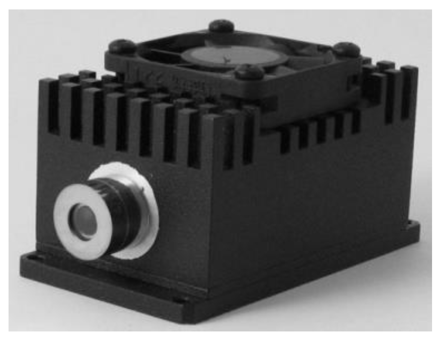
Figure 1. Broadband detection module of the VPAC series with a biased photodiode [23].
Electronics 10 00875 g001
Figure 2. Block diagram of the detection module. TEC, thermoelectric cooler; EMI, electromagnetic noise filter; SubMiniature version B connector (SMB).
Electronics 10 00875 g002
Figure 3. A diagram of the free space optics communication (FSO) system transmitter module.
Electronics 10 00875 g003
Figure 4. Photo of the receiving (a) and transmitting (b) modules of the FSO link.
Electronics 10 00875 g004
Figure 5. Scheme of the research position for testing the FSO link in laboratory conditions. LDD, laser diode driver; QC, quantum cascade.
Electronics 10 00875 g005
Figure 6. Sample oscillogram obtained during bit error rate (BER) measurements.
Electronics 10 00875 g006
Figure 7. BER values for different pulse duty factors and frequencies at the laser operating temperature of −10 °C.
Electronics 10 00875 g007
Figure 8. BER values for different pulse duty factors and frequencies at the laser operating temperature of 0 °C.
Electronics 10 00875 g008
Figure 9. BER values for different pulse duty factors and frequencies at the laser operating temperature of 20 °C.
Electronics 10 00875 g009
Figure 10. The scheme of the measurement of the FSO link in the real conditions.
Electronics 10 00875 g010
Figure 11. The laboratory stands for testing the FSO link outside the Military University of Technology building.
Electronics 10 00875 g011
Figure 12. Experimental results in the real conditions for a light haze (violet) with marked theoretical calculations (pink) in the case of (a) attenuation of the wavelength 1.5 µm, (b) attenuation of the wavelength 10 µm (c) visibility.
Electronics 10 00875 g012
Table 1. The basic parameters of the detection module optimized for a wavelength range of 10 μm [9].
ParameterUnitValue
Transimpedance @RLOAD = 50 ΩV/A13.5 × 103
Output resistanceΩ50
Gain bandwidthMHz0.001÷780
Noise voltagenV/Hz1/2190
Voltage sensitivity V/W2.1 × 105
Detectivity cmHz1/2/W3 × 1010
Table 2. Parameters of the pulses generated by the Picosecond 12,000 generator, for which the BER studies were conducted.
ParameterValue
Type of workPseudo-random sequence
The length of the generated code15,000 bits
Character length14
Code typeRZ (return to zero)
Pulse frequencyfrom 500 kHz to 9.0 MHz
Pulse duty cyclefrom 0.5% to 40%
Operating temperature of the laserfrom −10 °C to 20 °C
Low-level voltage4.5 V
High-level voltage0 V
Publisher’s Note: MDPI stays neutral with regard to jurisdictional claims in published maps and institutional affiliations.