1. Introduction
Internet of Things (IoT) has become an indispensable element of information technology, predicted to continue to grow at a rapid rate. It is a concept of ubiquitous computing technology such as sensors, actuators, mobile phones [
1] that interact altogether with the use of wireless technologies that have been rapidly emerging in recent years. IoT systems that communicate data over shorter distances or exchange more data in real time are likely to use GHz-based network protocols (WiFi, Bluetooth, or ZigBee), while systems that prioritize longer distance communications will consume less power, and those who can tolerate only lower data rates are more inclined towards network protocols operating at MHz frequencies and having lower power consumption, namely Low-Power Wide-Area (LPWA) networks such as Long Range (LoRa) (LoRaWAN) [
2], SigFox [
3] or NarrowBand-Internet of Things (NB-IoT) [
4,
5].
Low-Power Wide-Area (LPWA) networks are emerging as the enabling technology for the development of smart ecosystems such as smart cities. The potential of LPWA technology is immense. The emerging network technology that enters the region of smart cities is the LPWA, characterized by low power consumption, low data rates, and long range (up to 15 km outdoors). Due to its simple set-up, it is already used for monitoring of parking availability, packet delivery, smart lighting, waste management, pollution monitoring, livestock management, and even pest control [
6]. Because of these characteristics, LPWA is an ideal candidate for establishing communication between remote devices that have difficult access conditions [
7]. Nowadays, LoRa (Long Range) wireless technology has proven to be a good candidate for communication over long distances regarding IoT, and the reason is that LoRa provides control and management capabilities for IoT devices over long distances with very low power consumption, greatly extending the battery life of devices [
8,
9].
LoRa, SigFox, and NB-IoT use an unlicensed Industrial, Scientific, and Medical (ISM) frequency spectrum, characterized by low data rates, differing in communication mode, data transfer rate, installation cost, and openness to the end user. LoRa as a LPWA technology uses Chirp Spread Spectrum (CSS) modulation. On the other hand, LoRaWAN presents one of the most widely adopted LPWA technologies that utilizes LoRa radio technology. Their ability to provide long-range communication relies on the chirp spread spectrum modulation technique as well as the unlicensed ISM sub-1GHz transmission frequency band, depending on the frequency plan of a specific region (e.g., for Europe, it is from 863 to 879 MHz and 433 MHz). A frequency plan defines not only the frequency channels in the specific region, but also the spreading factor, bandwidth, and packet payload. Being relatively new, the LoRaWAN standard is still being developed, and many security and privacy problems are being discovered every day [
10,
11,
12,
13]. The possibility of depleting energy from battery-operated end devices by using Energy Depletion Attack (EDA) was introduced in [
14]. One of the basic problems of LoRaWAN networks is the possibility of being congested. Since LoRaWAN devices do not have coordinated Medium Access Control (MAC), simultaneous transmission from two devices using the same spreading factor and frequency band will result in dropping the packet from the device with lower signal power at the receiver side. LoRaWAN as a standard tries to minimize/escape the problem of congestion using a fair duty cycle between message transmissions that complies with the European Telecommunications Standards Institute (ETSI) regulations (commonly set to 1%) [
15]. This scenario is not far-fetched if we assume that, in the future, hundreds or even thousands of LoRaWAN devices will be in the radio range of each other.
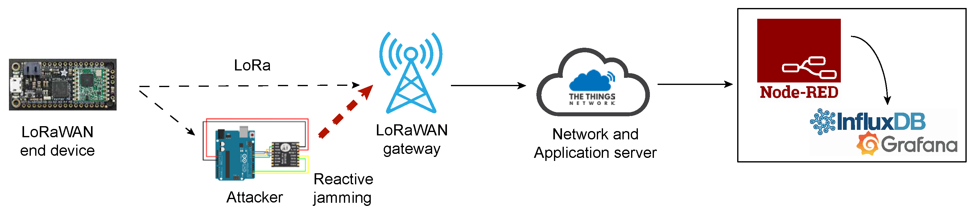
The nature of LoRaWAN makes it easy for adversaries to jam the message from large distances, “covering” a big part of a city [
16,
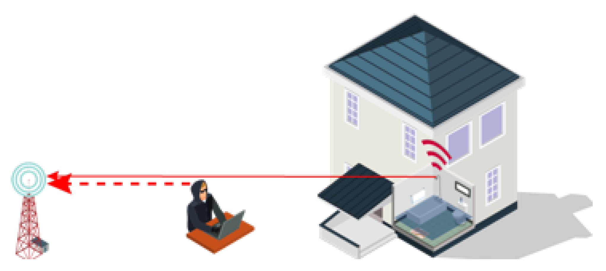
17]. Safety-critical applications such as alarm reporting, fire detection, asset tracking, radiation, and leak detection could be potentially jammed by an adversary (
Figure 1). Similarly, as two LPWA devices can interfere with each other, a malicious attacker can easily violate message integrity by jamming these devices or network gateways [
16,
18]. Indeed, LoRaWAN frame collisions were well studied in [
19], while jamming on LoRaWAN was introduced in [
17]. The attack was successfully implemented on commodity hardware and successfully executed on devices with larger spreading factors. Furthermore, a selective jamming attack was executed on devices with a specific LoRaWAN address. LoRaWAN security issues have been introduced in a recent publication [
20], where jamming techniques present a serious issue. The possibility for the attacker to mount a bit-flipping attack during message transmission was the concern of several research papers [
10,
11,
21,
22,
23]. Moreover, the low cost nature of LoRaWAN devices allows a malicious attacker to mount jamming attacks using off-the-shelf components such as a radio module (e.g., LoRa) and Arduino. As shown in [
16], commodity hardware is suitable only for large Spreading Factors (SFs) that require a long time to convey information over the radio. In this paper, we want to explore the possibility to violate the message integrity by applying low-cost but still efficient reactive jamming techniques that will disrupt the network. Given this setting, the attacker executes reactive jamming on a detected packet transmission.
This paper presents an extension of the paper previously published in SpliTech conference [
24]. In a conference paper, it was shown how an attacker can easily perform a reactive jammer attack on LoRa communication at 433 MHz frequency channel. It was only briefly shown that such an attack has a potential to be extended to cover a commercial LoRaWAN network operating at 868 MHz frequency. However, such an attack is only suitable for single-channel LoRaWAN networks (gateways) with specific spreading factor and bandwidth, whereas LoRaWAN as a standard covers multiple channels as well as spreading factors and bandwidths, which may result in a potential expensive attack. In this paper, it is shown how easily an adversary equipped with low-cost devices can perform a jamming attack on the communication between a legitimate end device and the gateway simply by observing LoRaWAN transmission from the legitimate device and jamming the rest of the message. Jamming is realized simply by transmitting a message with higher signal strength from a device placed close to the gateway device. To achieve high efficiency in the implemented LoRaWAN jammer, three forms of attack were considered:
Reactive jamming on fixed channel: utilizing a Channel Activity Detection (CAD) mechanism supported by LoRa devices, Reactive jammer listens to LoRa channel activity and upon detecting message transmission, sends its own packet to force collisions and violate the correct LoRaWAN message reception. As shown, such a setup is quite expensive, as indicated in [
24].
Continuous transmission with channel hopping: to create a low-cost jamming device, in this scenario, the adversary simply performs channel hopping and transmits LoRa packets. This way, without detecting any LoRaWAN transmissions, the attacker continuously performs channel hopping and LoRa packet transmit, introducing collisions in the LoRaWAN network.
Reactive jamming with channel hopping: In this setup, the device performs channel hopping, but only sends packets upon successful CAD detection, thereby realizing a reactive jammer. Compared with the above two strategies, it was shown that such a setup results in the best trade-off between attack efficiency and setup cost.
2. LoRa/LoRaWAN Message Transmission
In this section, the basic concepts that build LoRa message transmission are described, ranging from CSS modulation to the spreading factor, bandwidth, along with the frequency channels. LoRaWAN [
15], as a network protocol that uses LoRa, is also described in this section.
2.1. CSS Modulation
LoRa utilizes Chirp Spread Spectrum (CSS) modulation [
25] for message transmission from the end node to the gateway (and otherwise). CSS is a modulation process in which information is modulated by frequency chirps (frequency rise/decrease over a period of time). The use of CSS modulation increases the robustness of the LoRa network and the signal resistance to interference. CSS is a spread spectrum technique in which the signal is divided into different frequency domains. An example of LoRa-based signal modulated with CSS technique can be found in
Figure 2.
2.2. Carrier Frequency (CF)
Carrier frequency determines the frequency for LoRa transmission. Several frequency bands are supported for LoRa transmission, and they range from 137 MHz up to 1020 MHz.
2.3. Coding Rate (CR)
LoRa modem uses Coding Rate for protecting against bursts of interference. This is defined by Forward Error Correction rate that can take CR values 4/5, 4/6, 4/7, or 4/8. With larger CR, the packet time-on-air will be higher at the expense of more protection [
26].
2.4. Spreading Factor (SF)
A Spreading Factor (SF) is a size that defines the amount of data or bits that can be encoded by a single symbol. In addition to defining the number of bits that can be encoded by a single symbol, the spreading factor also gives information that a symbol of SF bits can be encoded in the range from 0 to . For example, if SF = 7, then 0–127 different values of one symbol can be encoded. In addition, to determine the number of data that can be encoded by a single symbol, SF also determines the duration of each chirp/chip, and hence the transmission time of the entire packet. Increasing SF results in the increase in the total transmission time of the entire packet. However, it is important to note that a larger SF results in a longer transmission range and higher resistance to interference.
2.5. Bandwidth (BW)
In LoRa, the Bandwidth (BW) determines the frequency width used in the transmission frequency band. Chip rate represents the number of chips sent within a period of one second. Since the chirp rate is directly related to the bandwidth, a higher bandwidth will result in a larger chip rate. For example, if BW equals 125 kHz, then the generated number of chips per second will be 125,000. Semtech explains the relationship between the spreading factor and the bandwidth [
27]. By increasing BW for the fixed SF, the bitrate will increase as the number of chips sent per second also increases with BW (
Table 1). LoRa supports BW from 7.8 kHz to 500 kHz; however, in the implementation of LoRaWAN, only BWs of 125, 250, and 500 kHz are being utilized. Otherwise, for the fixed BW, increasing the SF, the bitrate will decrease as depicted in
Table 2.
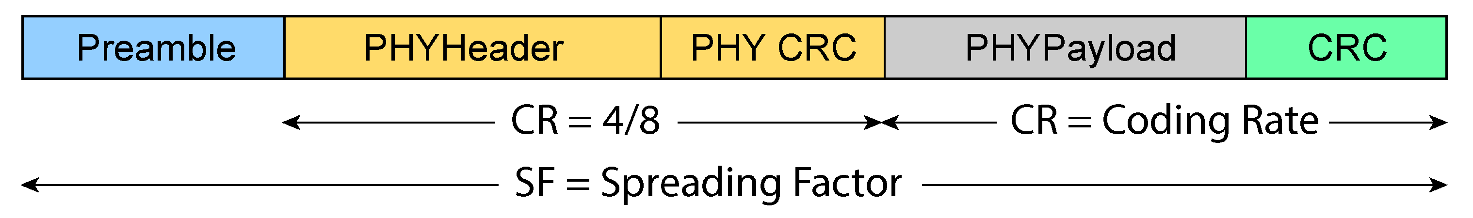
Two frame formats are supported by LoRa [
28]. In the explicit frame format shown in
Figure 3, a header frame is used, which holds information about the payload length, CR being used, and information on whether an optional Cyclic Redundancy Check (CRC) payload is used. In the implicit frame format, only the payload is used. In both formats, the preamble is used for receiver synchronization. Preamble length can go from 6 to 65,535 symbols. Preamble is combined with an additional 4.25 symbols added by LoRa modem, which results in a synchronization word. For example, the preamble length in LoRaWAN is six symbols. The preamble is followed by a header part of the packet with a coding rate set to 4/8, which is followed by a payload with size ranging from 1 to 255 bytes.
3. LoRaWAN
LoRaWAN represents Medium Access Control (MAC) protocol aimed at low-power (mainly battery-operated) devices in wide-area network systems. The first specification of this protocol was released in 2015, and a new specification was released in 2017. LoRaWAN uses an unlicensed ISM frequency spectrum characterized by a low data rate, whereas the frequency spectrum depends on the utilized region. In every region, a portion of the ISM frequency spectrum has been defined and allocated exclusively to that region for realizing LoRa traffic. For example, in Europe, a frequency range from 863 to 870 MHz and a fixed frequency of 433 MHz is intended for LoRa transmission. For each frequency plan, the parameters necessary for the uplink and downlink communication between the LoRa module and the gateway are defined, such as the Spreading Factor (SF) and Bandwidth (BW).
As defined by LoRaWAN specification, for the EU region, end devices should be able to operate on at least 16 frequency channels within the frequency band from 863 to 870 MHz. It is determined that the first three channels should correspond to 868.1, 868.3, and 868.5 MHz frequencies, and as such, it is guaranteed to be implemented between end devices and gateways. Indeed, the European Telecommunications Standards Institute (ETSI) standard [
29] also requires that each of the LoRa modules using the EU863-870 frequency plan must have three predefined channels implemented, namely:
868.10 MHz, bandwidth = 125 kHz,
868.30 MHz, bandwidth = 125 kHz,
868.50 MHz, bandwidth = 125 kHz.
Uplink channels are intended for sending data in the direction from LoRa end device to the gateway, while downlink channels are intended exclusively for sending data in the direction from the gateway to LoRa end devices. The EU region also supports operating at frequency channels within the range from 433.05 to 434.79 MHz. During the downlink communication, LoRa module opens 2 time frames within which the gateway is expected to respond. Within the first time frame, the downlink channel frequency is the same as for the uplink, while for the second time frame, a fixed predefined data rate and frequency are determined. As a default parameter, frequency 869.525 MHz, SF12, and 125 kHz bandwidth is used (The Things Network—TTN—uses nonstandard SF9 and BW 125 kHz data rate on frequency 869.525 MHz).
In the ETSI standard, the 863-870 MHz band is divided into five additional frequency bands, namely, G, G1, G2, G3, and G4. Each of these areas has precisely specified limitations (
Table 3), such as the frequency range and duty cycle.
The duty cycle defines the maximum percentage of a certain period of time within which an individual device (LoRa module or gateway) can use a particular channel, i.e., transmit its packets. After sending the data, the device must wait until the period expires to continue transmitting the data. Using a duty cycle, the chance of collision during packet transmission between two or more legitimate devices will be reduced.
LoRaWAN uses the following three bandwidth ranges: 125 kHz, 250 kHz and 500 kHz. Which of these three bands will be used depends solely on the frequency band defined for the particular regional area (e.g., 125 kHz and 250 kHz bandwidths are used in Europe). Based on the bandwidth and operating frequency, the lower and upper cutoff frequency can be determined. The lower cutoff frequency equals the difference between the operating frequency and half of the bandwidth, while the upper cutoff equals the sum of these two values. Therefore, for an operating frequency of 867.1 MHz, the lower cutoff frequency will be 867.0375 MHz and the upper will be 867.1625 MHz for 125 kHz bandwidth.
For the transmission power of end devices and gateway, there are six possible options defined: 2, 5, 8, 11, 14, and 20 dBm. For the frequency region, EU863-870 14 dBm is defined as a default transmission power, although G3 band can use transmission power up to 27 dBm, which is typically used for downlink.
3.1. LoRaWAN Architecture
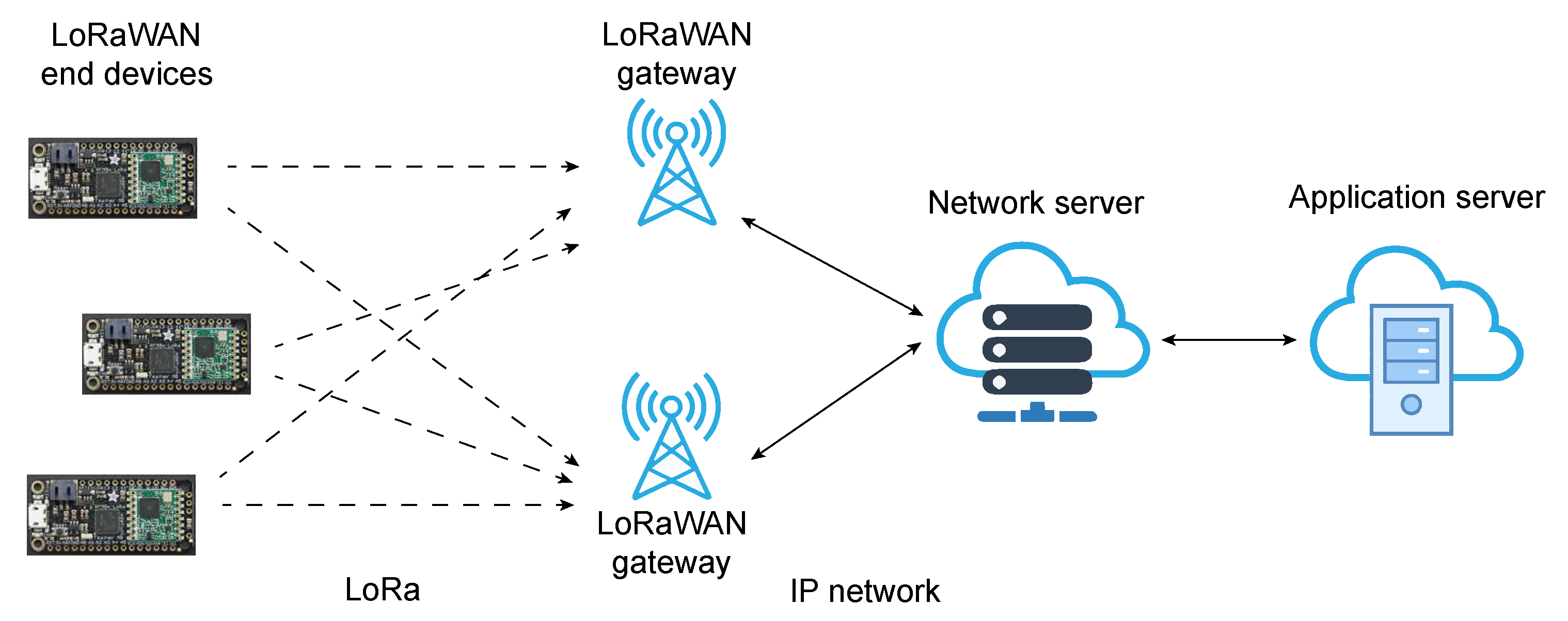
LoRaWAN uses a star network topology (
Figure 4) in which there are three main participants, namely LoRa modules (End Nodes), which can be designed for a variety of applications; one (or more) LoRa gateways; and a central network server. The gateway forwards packets received between the LoRa module and the central network server. LoRaWAN network protocol is used to send packets between modules and gateways, while traffic between the gateway and the central server is established via some fast network technologies such as WiFi, Ethernet, 4G, and 5G. The central server further transmits the received packets to the application server, which then processes them for further application usages.
3.2. End Devices
LoRaWAN end nodes can be divided into three classes, Class A, Class B, and Class C [
30]. On a high level, Class A devices are implemented in a way to send information at any time to the gateway device, usually when some events occur, as they are aimed at reducing the battery consumption of mainly battery-operated devices. Class B devices are time-synchronized and have a particular time slot inside which communication occurs. At the end, Class C devices are always active (powered on) intended for immediate message reception from gateways.
Moreover, as shown in this paper, the low-cost nature of LPWA devices allows a malicious attacker to mount jamming attacks using off-the-shelf components such as a radio module (e.g., LoRa) and Arduino.
3.3. Structure of the LoRaWAN Packet
The structure of the LoRaWAN packet is defined by the LoRaWAN specification and is shown in
Figure 5. Transmission of LoRa packets is initiated by a preamble, which is followed by the radio layer along with a MAC layer of a packet.
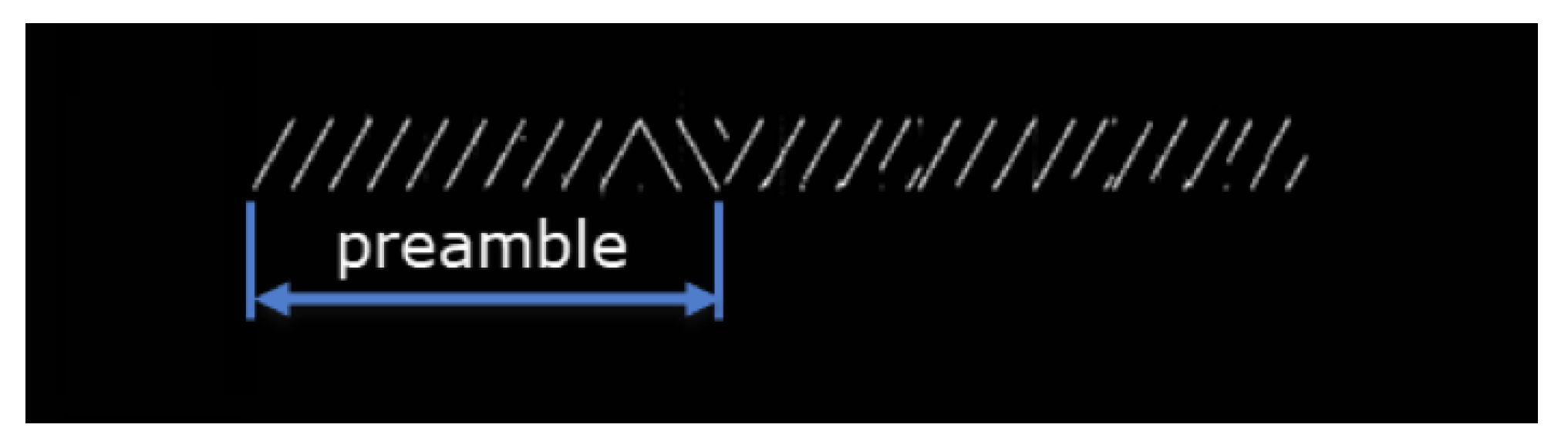
The preamble header is an essential part of the packet since the receiver filters the incoming traffic from the received preamble, i.e., determines whether the packet is intended for it or not. The preamble header consists of a number of up-chirps, which is followed by an additional two up-chirps and 2.25 down-chirps (
Figure 2). The last 4.25 chirp marks the end of the preamble header. At the moment of receiving the preamble, the only thing the receiver can know is that there is some LoRa module that transmits packets; what it cannot know is to which LoRa module these packets belong. The preamble plays a large role in filtering modulated signals precisely because of the fact that the LoRa standard operates on the ISM radio frequencies it uses and the large number of unlicensed devices transmitting its signals, so correct detection of the LoRa signal is crucial. The MAC layer is located above the physical layer and is responsible for encrypting application data. The MAC layer defines the MAC header (specifies the message type), MAC payload (contains encrypted information). MAC payload header is followed by the Message Integrity Code (MIC) header [
31], which ensures the integrity of the part of the packet using AES-128 CMAC protocol and NwkSKey (Network Session Key) key. LoRaWAN generates network NwkSKey and AppSKey (Application Session Key) from the 128-bit AES AppKey (Application Key). AppSKey is used to encrypt the application payload FRMPayload with AES-128 in Counter mode (CTR).
The MAC payload also includes a Frame Header (FHDR) within which the first four bytes represent the address of the end device to which the packet belongs. Along with the device address, FHDR contains a Frame Counter that is incremented with every subsequent packet. Frame Counter (FCnt) in LoRaWAN is also used to prevent possible replay attacks.
4. Analysis of LoRa Communication for the Implementation of Reactive Jammer Attack
What makes LoRaWAN traffic robust is the fact that it is more collision-resistant than other systems and will not cause packet loss due to the fact that LoRa uses CSS modulation. If two packets are simultaneously transmitted over the same frequency channel, but with different spreading factors, the LoRaWAN gateway will receive both packets without loss. However, if packets are modulated with the same spreading factor, the collision will result in the loss of all packets except for the packet with the highest signal strength at the receiving side. If two packets arrive with the similar signal strength at the gateway (with the same spreading factors), they will both be rejected as the gateway will detect either a faulty preamble or CRC error. For one of the two cases described above to occur, it is sufficient for the signal collision to modify one chirp of the modulated signal in the preamble portion or in the rest of the packet.
Knowing the fact that collisions may occur, along with the fact that LoRaWAN message airtime is quite large, an adversary can easily create its own jammer that will send packets only when a message from the legitimate device occurs. However, it is important to note that a collision can only occur if an adversary sends its packet on the same frequency channel, which uses the same spreading factor as the packet sent by the legitimate device. Next, we describe possible mechanisms for the detection of LoRaWAN transmission.
CAD Detection Mechanism
As noted in the Introduction, the aim of this paper is to implement a simple and inexpensive reactive jammer on the detected transmission of LoRaWAN packets from a legitimate device.
There are two ways in which LoRa radio modules can detect activity on a LoRa radio channel. In the first scenario, the Received Signal Strength Indication (RSSI) signal from the LoRa device is observed. However, RSSI is a relative measure of the total energy that the radio module receives on the receiving side via an antenna on a particular channel (frequency). Such a mechanism can represent a signal coming from a LoRa-based radio module, as well as from other radio devices that transmit on the same frequency, since ISI frequency spectrum allows simultaneous transmission of various radio technologies. Therefore, the proposed signal detection method of the LoRa signal transmission does not seem practical for the realization of a reactive attack.
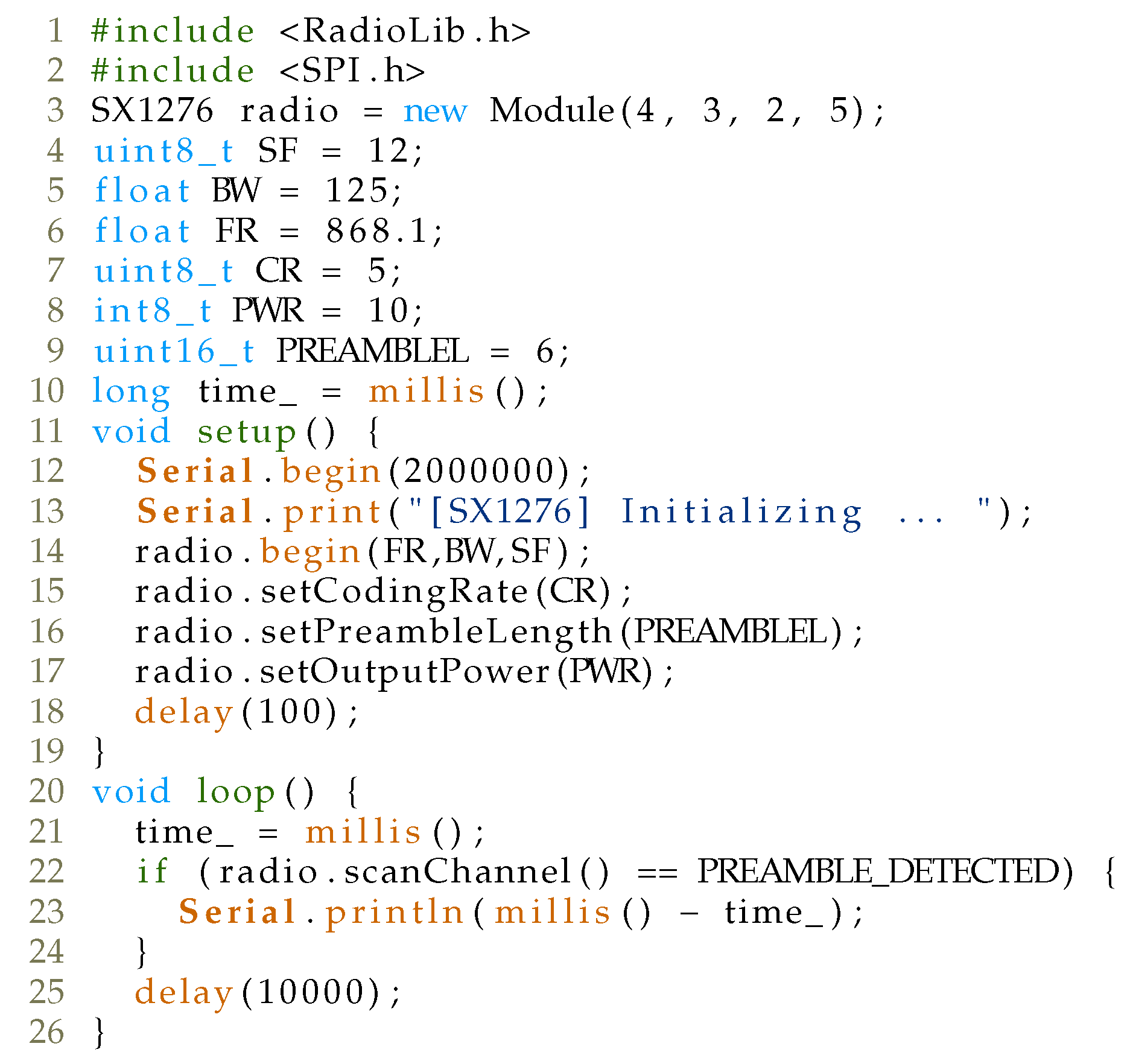
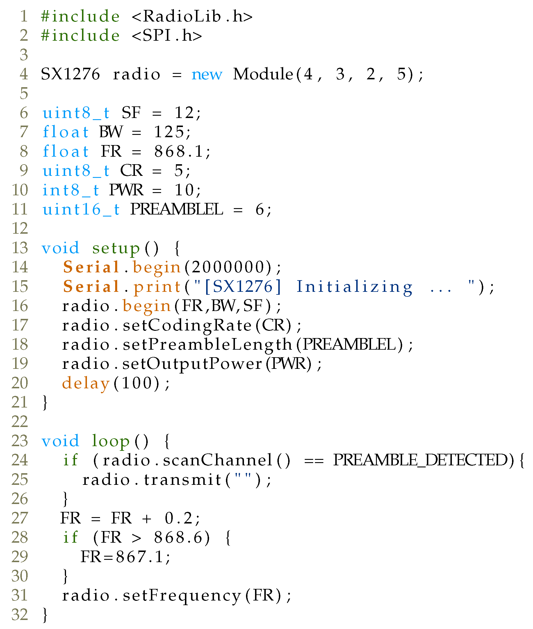
The second mechanism for detecting the transmission of LoRa signal is called Channel Activity Detection (CAD) and is intended for LoRa modules for detecting the preamble of LoRa packets. In a CAD mechanism, the LoRa device samples a signal of approximately one symbol length on a specific channel and calculates the correlation between the captured symbol and the ideal LoRa symbol for a given SF. The moment a large correlation is obtained, CAD detection interrupt is activated, or otherwise, a CAD-done interrupt. The duration of this operation is approximately two symbols, as shown in
Table 4, where comparison of the duration of the CAD mechanism in symbols for different SF and for BW 125 kHz is given. In parallel with the theoretical duration of the CAD mechanism given in [
32], CAD time measurements were also made with LoRa modem and Arduino UNO, while RadioLib (
https://github.com/jgromes/RadioLib, accessed on 22 January 2021) library was employed for testing purposes, with the code shown in
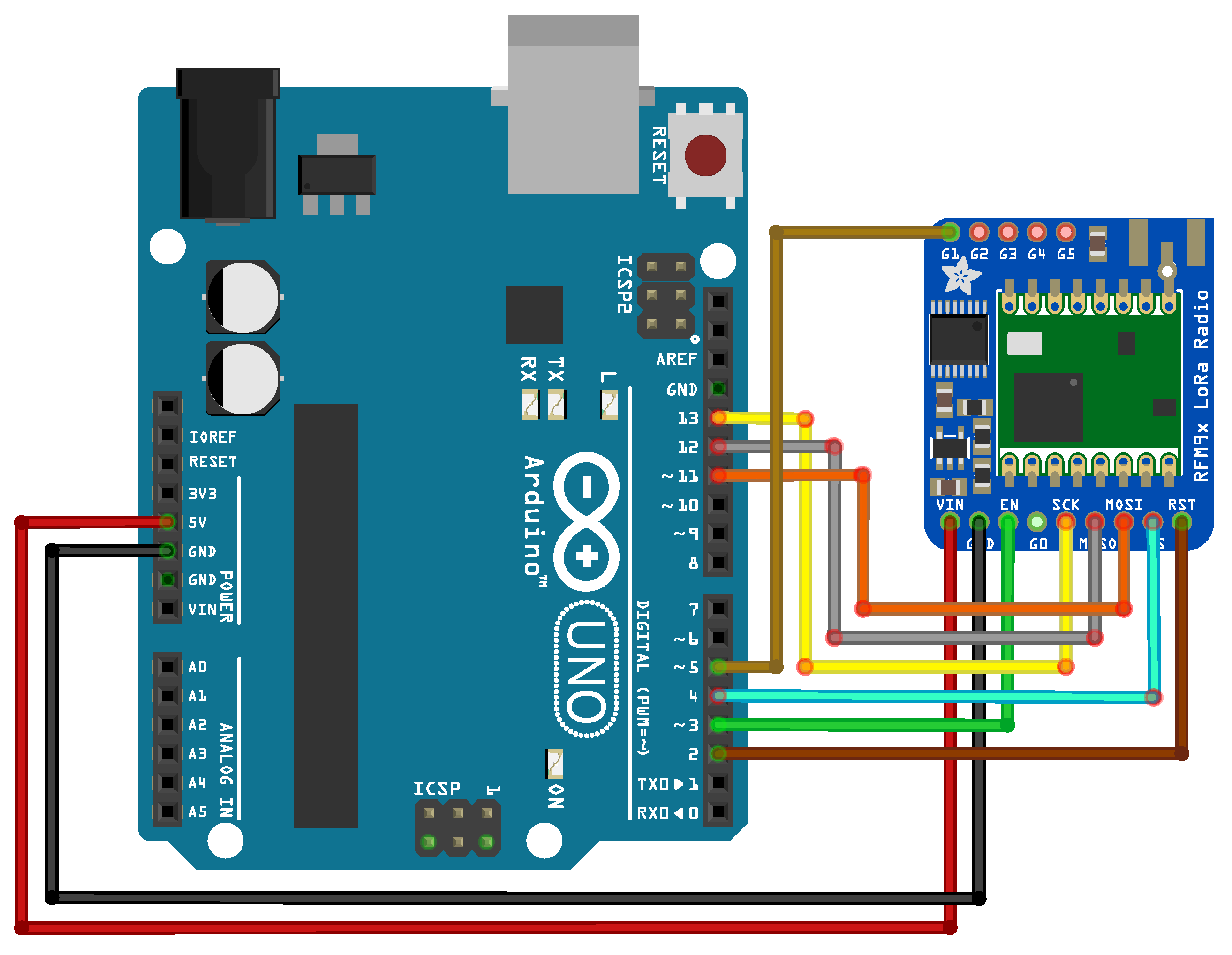
Figure 6. Wiring of the complete setup comprising LoRa modem and Arduino UNO is depicted in
Figure 7.
During the test, the LoRaWAN device sent messages at random 100 times for SF ranging from 7 to 12 and BW 125 kHz on a fixed channel, while the Arduino device with a LoRa modem measured the detection period of the CAD mechanism. As can be seen in
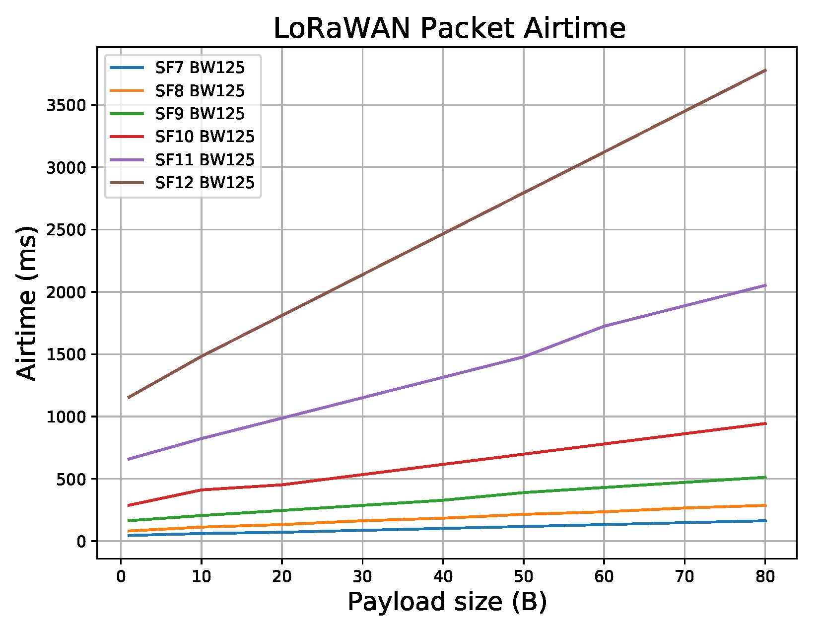
Table 4, the captured CAD times are similar to the estimated CAD duration. For comparison,
Figure 8 shows LoRaWAN packet airtime for various payload sizes ranging from 1 to 80 Bytes, for SF7–SF12, with BW equal to 125 kHz. (Please note that the standard payload overhead of 13 bytes is included in the packet payload (PHYPayload in
Figure 5): (1), DevAddr (4), FCtrl (1), FCnt (2) and (4) and Fport (1). MAC header (MHDR) Message Integrity Code (MIC). As can be seen, the CAD detection mechanism allows enough time for the attacker to mount a reactive jammer attack after the CAD-done interrupt has been activated. Next, several strategies are introduced that exhibit a reactive jamming attack on LoRaWAN network, aimed at finding one that reduces the price of the setup, while leaving the attack efficiency high.
5. Implementation of Reactive Jammer Attack
This section describes in detail three forms of jammer attack on a LoRaWAN network.
5.1. Attack Strategy 1: Reactive Jamming Using CAD Detect and Transmit on a Fixed Channel
As can be seen from the previous section, a CAD mechanism can be employed to detect the transmission of a LoRaWAN packet sent on a specific channel and SF and cause collision on the gateway by sending a higher power packet afterwards.
Specifically, the LoRaWAN protocol covers the frequency plan that defines not only the frequency channels in the specific region, but also the spreading factor (SF), bandwidth (BW), and packet payload size for the given SF. For example, for the EU868 region, eight packet transmission channels have been allocated, with a spreading factor ranging from SF7 to SF12 and a BW of 125 kHz. Note that The Things Network (TTN) also utilizes SF7 and BW 250 kHz with frequency channel 868.3 MHz. Our analysis, as well as the analysis in [
33], indicates that 125 kHz bandwidth is always used with various spreading factors. However, to successfully implement a reactive jammer attack using commodity hardware, an adversary should listen to the CAD mechanism implemented on the same channel with the same SF at which a legitimate LoRaWAN packet is sent and then cause a collision on that particular channel by sending a packet that will be received by the gateway with a higher signal strength.
To test the implementation of a reactive jammer attack, a gateway was placed on a geographical location where there are no transmissions from other LoRaWAN devices. Since its operating frequency was configured at 868 MHz (EU868 region), an RFM95W (
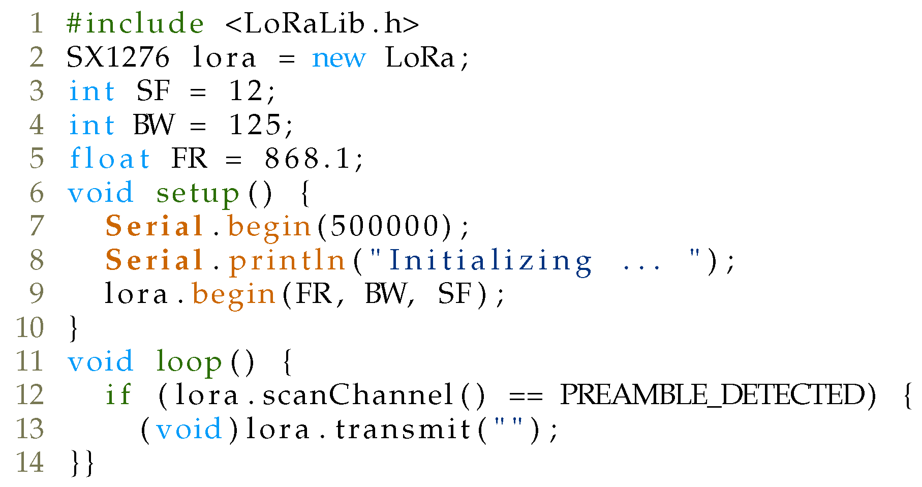
https://www.hoperf.com/modules/lora/RFM95.html, accessed on 22 January 2021)-based LoRa module was used that supports this operating frequency. The code for provoking collisions is shown in
Figure 9.
Figure 10 depicts the architecture of our attack. During the test, our jammer was placed around 1 m from the legitimate gateway device. As a legitimate device, the Adafruit Feather M0 with RFM95 LoRa (
https://www.adafruit.com/product/3178, accessed on 22 January 2021) module was utilized, while RAK831 concentrator module was utilized as a LoRaWAN gateway (
https://www.thethingsnetwork.org/docs/gateways/rak831, accessed on 22 January 2021). The legitimate device was placed at the same floor as our jammer, around 5 m from the gateway. Our setup in which a legitimate device is placed very close to the gateway (around 5 m) and the reactive jammer even closer (1 m) resulted from an increasing number of LoRaWAN devices placed in our university environment. To create a test setup environment in which the reactive jammer would only respond/react to message transmission from our legitimate device, and not other devices around us, an environment was created in which there was no LoRa communication from other devices. Specifically, the test setup environment was conducted in a basement, around 30 km from the nearest LoRaWAN gateway. Indeed, in a more realistic scenario, where a legitimate device is placed around 10 km from the gateway, while a jammer is placed 2 km from the gateway, we believe that the results of the proposed reactive jammer attack would still be similar to the one achieved with our test setup environment, since the attacker would be placed in the middle between the legitimate gateway and the device. Such a realistic scenario would require a slightly modified setup, having a better antenna sensitivity on the jammer side to capture LoRa signal from legitimate device below the noise level. Laboratory tests are only a first step, while thorough tests in a realistic scenario are planned for future work.
Our LoRaWAN gateway employs connection to The Things Network (TTN) infrastructure. Here, TTN implements both application and network servers. To detect the result of our attack, every message was forwarded to our own personal server comprising Node-RED, InfluxDB database and Grafana for further processing and visualization. When a message from legitimate device occurs, the jammer successfully employs collision and disables the the reception of legitimate messages on the gateway since the signal from the jammer is higher than from the legitimate device on the receiving side of the gateway.
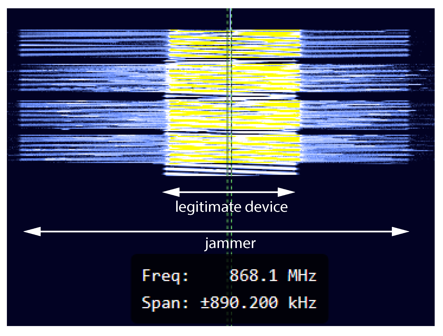
Figure 11 shows a snapshot of the transmission of both legitimate and jammer packets at frequency 868.1 MHz with SF12. Trace was captured using HackRF One and GQRX Software Defined Radio receiver (SDR). As can be seen, during the transmission of LoRaWAN packets, an attacker first utilizes CAD detection, which is followed by a transmission of its own packet of higher signal strength.
In the first phase, testing was carried out at operating frequency of 868.1 MHz and 125 kHz bandwidth. Each test was performed individually with different spreading factors (from SF7 to SF12) and different payload sizes (from 10 up to 40 bytes), which can be seen in
Table 5. What is important to note is that the percentage of discarded packets does not depend on the change in the spreading factor or the payload size. The jammer sends its packet in a very short time after detecting the transmitted packet. This period is more than sufficient to cause a collision that causes the gateway to reject the received packet.
While this scenario is quite simple to implement on single-channel gateways (with a specific SF), for EU868 region, an attacker would simultaneously implement CAD detection for the unique combination of six SFs and eight channels (assuming only BW 125 kHz is utilized). Specifically, the attacker requires at least devices (Arduino + LoRa module), each of which listens to the CAD mechanism on its channel and SF and sends its message upon CAD detection interrupt. However, the price of such a setup is quite expensive, and another strategy should be utilized that reduces the number of devices but still maintains a high percentage of the attack success. Hence, the idea is to find a strategy that would reduce the number of devices but still keep high efficiency in a reactive jamming attack.
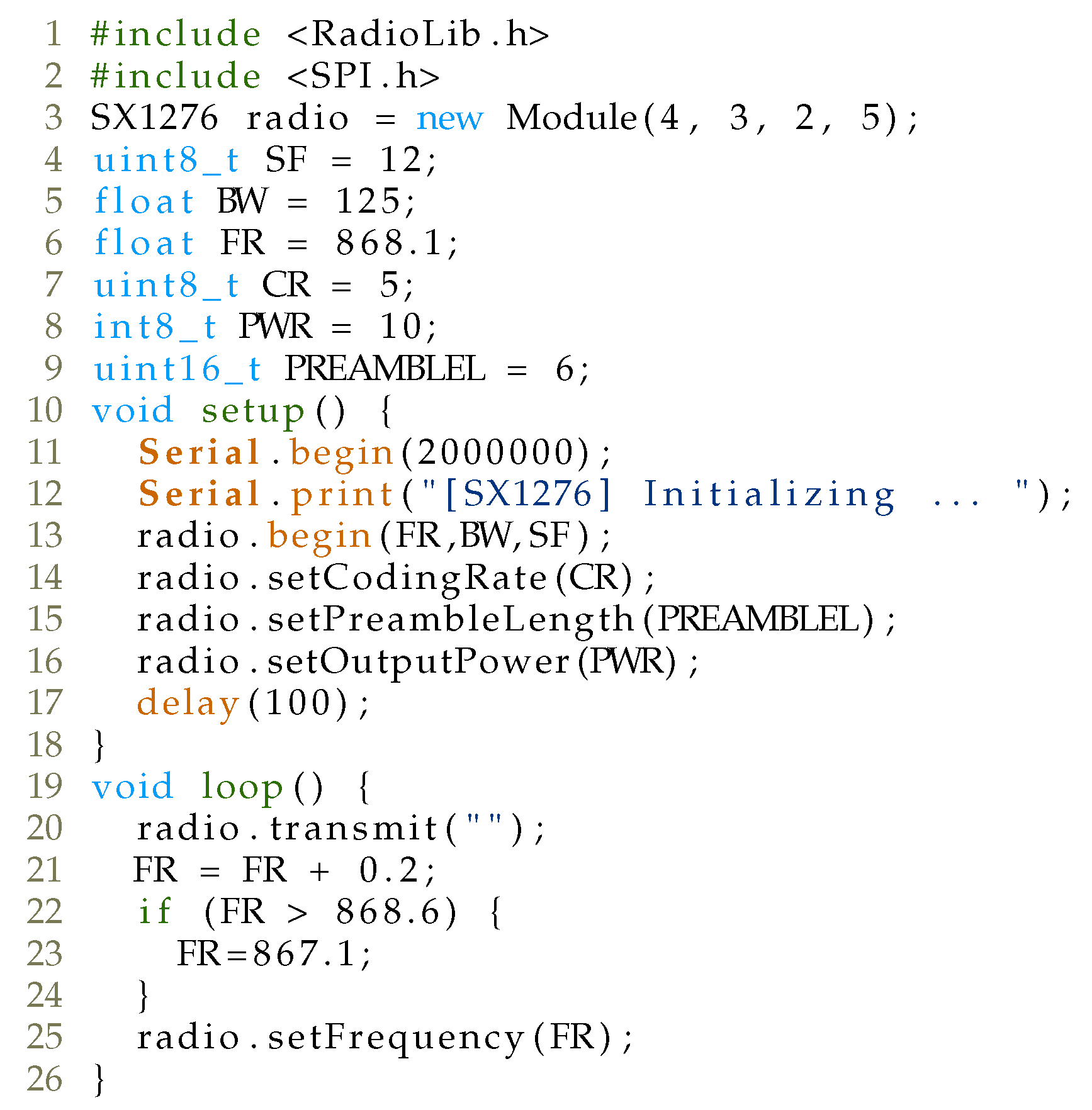
5.2. Attack Strategy 2: Channel Hopping and Transmission
Another strategy for the attacker to implement jamming would include a combination of channel hopping and transmission. This way, the attacker does not have to listen for the beginning of LoRaWAN communication, but instead simply transmits the message on the channel. Instead of continuous transmission on a single channel, the attacker could transmit a message on a channel for a given SF and then jump to the next frequency channel and perform transmission. This way, the number of LoRa-enabled devices would be reduced from 48 to 6 for every specific SF7 to SF12 (SF).
As can be seen from the code, the device is placed on the frequency channel with a fixed spreading factor and bandwidth. Once the device sends an empty LoRa packet payload, it jumps to the next channel and repeats the transmission again.
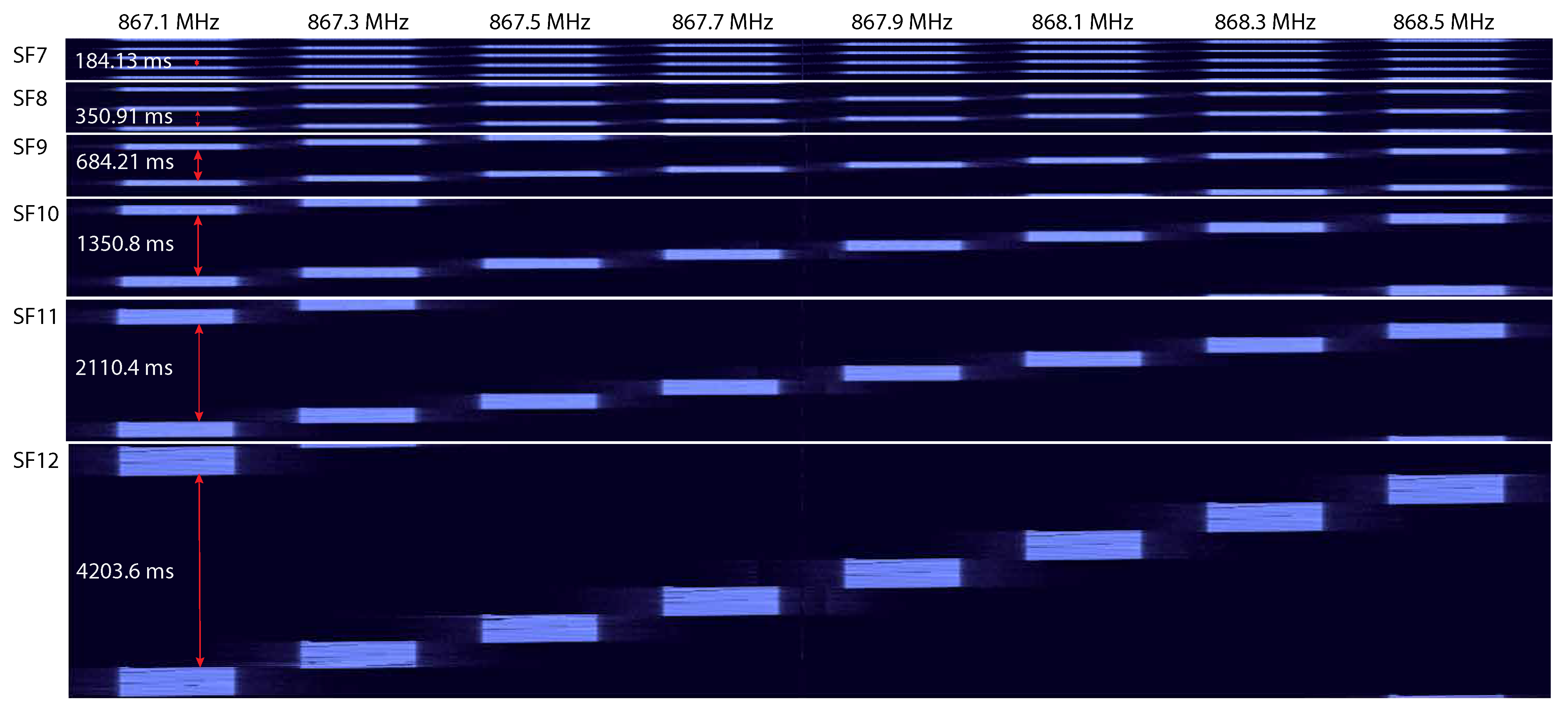
Figure 13 shows the results of transmit and hop strategy for different spreading factors captured with HackRF One and GQRX SDR. By comparing the time a single jammer device is required to complete the full cycle with the transmission period of a legitimate LoRaWAN packet, it can be clearly seen that although the number of devices for the implementation of the attack is reduced, the form of such attack will not be effective as with the first strategy. As can be seen, it takes approximately 4203.6 ms to transmit LoRa packets with an empty payload on all eight channels with channel hopping using SF 12 and BW 125 kHz. It can also be seen that, once the adversary transmits on a single channel, it takes more than 4 s to transmit on all seven other channels. During that period, as an example, a legitimate LoRaWAN packet with 80 bytes in payload with SF12 and BW 125 kHz will have enough time to be conveyed to the gateway, as its time-on-air is 3776.5 ms. Clearly, if a message transmission occurs between two successive jammer transmissions, the attacker will not succeed with the attack. Moreover, with smaller payload packets, the attack success will be reduced, since this time difference becomes bigger when the payload size decreases.
5.3. Attack Strategy 3: Reactive Jammer with Channel Hopping, CAD Detection, and Transmission
Since the CAD mechanism is designed to detect the transmission of a LoRa packet preamble, the question arises whether the CAD mechanism works in the physical part of the packet. Namely, as specified in [
34], newer generations of LoRa modules enable CAD mechanism in the payload part of the packet as well (not only the preamble). Such a property of a CAD mechanism allows for the attacker to implement a reactive jammer attack not only after detecting the LoRaWAN packet in the preamble part of the packet but also in the payload part. This opens up the possibility for the attacker to detect LoRa transmission after a portion of the packet has already been sent and perform a reactive jammer attack after that.
To confirm the operation of CAD mechanism in the complete part of the packet, it was observed how many times during one packet transmission the CAD mechanism picks up an interrupt. During the test, the legitimate LoRaWAN device sent packets on a specific channel with a specific SF for various payload sizes (1, 10, 20, 30, 40, and 50 bytes), while a second LoRa-enabled device listened for packet transmission using the CAD mechanism and counted the number of detected interrupts during a single packet transmission.
Table 6 shows the test results of the CAD mechanism for LoRaWAN packets of different payloads. As can be seen, for different payload sizes with a specific SF, the number of CAD detections increases, which clearly indicates that CAD detection mechanism operates on the payload part of the LoRaWAN packet as well. Such a mechanism allows the attacker to potentially detect packet transmission using the CAD mechanism after a portion of the packet is sent. More notably, this allows the implementation of an attacker that performs channel hopping, executes the CAD mechanism, and, after issuing the CAD interrupt, sends a LoRa packet causing a collision (hop, CAD detect and transmit). Note that for the SF 10, the CAD detection mechanism fired the smallest number of interrupts compared to other SFs. This mechanism was detected with multiple radio modules as well. Hence, for future work, it is necessary to investigate such a behavior more in detail.
Table 7 compares the time it takes for a LoRa device to scan all eight channels for a specific SF and BW 125 kHz. This time includes the time of the CAD mechanism execution on all eight channels, along with approximately 1 ms to perform hopping from one channel to the next. Considering LoRaWAN packets with different payload sizes, it can be observed that in one scan cycle the LoRa jammer will most likely detect the LoRaWAN packet and execute an attack.
Figure 8 shows time-on-air for different payload lengths of LoRaWAN packages depending on SF, while time-on-air is also shown in
Table 7 for LoRaWAN packet with 1, 10, 20, and 30 Bytes payload size. Compared with the total time of the CAD mechanism for eight LoRaWAN channels, there is a high probability that the reactive jammer with the CAD mechanism will detect the presence of LoRaWAN packets and carry out its attack.
To confirm the implementation of our attack, an architecture for the implementation was utilized as depicted in
Figure 10, while the code for the attack is given in
Figure 14.
During the attack procedure, a legitimate LoRaWAN device is placed on a fixed channel with fixed SF and BW 125 kHz. Utilizing the duty cycle for a given SF, the device transmits at random a message of a fixed payload length. On the other hand, the adversary performs channel hopping and CAD detection. If the attacker detects LoRaWAN transmission, it simply transmits its own packet of fixed payload length. Otherwise, the attacker hops to the next channel and repeats the process again. The attack was performed for payload lengths 1, 13, and 25 bytes and specific SF, where the legitimate device sent 100 messages. The results are summarized in
Table 8. Please note, the attack was not utilized for SF10, since the LoRa radio module did not perform well with CAD detection mechanism, as depicted in
Table 6, where only a small number of CAD detections were observed during a single LoRaWAN packet transmission (e.g., only 16 with SF10 compared to 44 with SF11 for 50 bytes payload size). As expected, by increasing the payload size of a LoRaWAN packet, the success rate of the attack increases, as the adversary has enough time to perform channel hopping, CAD detection, and transmission. Taking into account that the average payload size is about 18 bytes [
33], it can be assumed that such a strategy will be successful in jammer implementation.
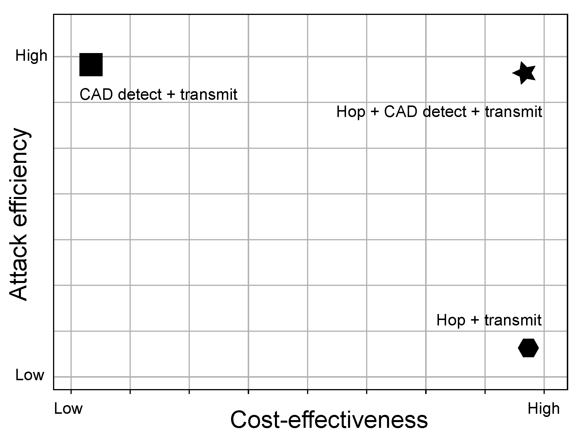
In
Figure 15, different jamming strategies are compared using LoRa-enabled devices with respect to their impact on both cost-effectiveness and efficiency of the attack. Clearly, strategy 3-Reactive Jammer with Channel Hopping, CAD detection and transmission-appears within the upper right corner. The proposed strategy has very good jamming success rate accuracy, but it also cost-efficient, as described further below. The first strategy, which achieves the best accuracy, is costly as it requires a single LoRa radio modem per combination of frequency channel, spreading factor and bandwidth, making it quite expensive for implementation. Hence, it appears in the upper left corner in
Figure 15. The price to achieve the attack with the second strategy is equal to the price of the third strategy, however, its accuracy is very small.
Table 9 shows price of the proposed LoRaWAN jammer device and its components used in its development. The microcontroller that supports LoRaWAN library is ATMega328P, whereas its representative Arduino Pro Mini can be found in a price range of 0.96 USD. To perform jamming over the radio, a RFM95 LoRa module could be employed, with a price of approximately 3.52 USD. Hence, the overall price of the module goes below 5 USD. The expensive version would comprise 48 devices to cover the EU868 region (employed by TTN), comprising eight channels and six spreading factors and BW 125 kHz, with the overall price being around 215 USD. On the other hand, a low-cost version with high attack accuracy requires only six devices to cover all spreading factors using frequency hopping. The price of the setup would cost less than 27 USD.
6. Countermeasures
Recall, the high efficiency of our attack introduced in the previous section is mainly due to the fact that long range nature of LoRaWAN packets comes at the cost of time it is necessary to convey information over the air. As introduced in recent research papers, there are multiple scenarios in which collisions in LoRaWAN network can be introduced. Using this knowledge, along with the low-cost nature of radio modules that support LoRa communication, the adversary can easily install its own device that supports reactive jamming, which causes collisions at the gateway. This section gives possible countermeasures to prevent against such types of attacks.
Note that the attack introduced in this paper operates in a scenario where the signal strength of the attacker device is stronger compared to the signal from the legitimate device at the gateway side. This implies that the success of such an attack requires the adversary to be at least close to the gateway (closer than the legitimate device). Hence, one of the easiest ways to reduce collisions, and generally collisions in LoRaWAN networks due to contention in high density environments, would require installing multiple gateways across a large area [
7]. This way, if the collision succeeds in one gateway, the attacker would also have to perform a collision with other gateways that are in the range of the legitimate device.
Another approach to prevent selective jamming, as well as reduction of contention in high-density LoRaWAN networks, would be to implement frequency hopping as introduced in [
35]. Using cryptographic primitives, end devices do not send messages on the same channel with the exact spreading factor, but instead randomly select the channel and spreading factor using cryptographic primitives. However, such an approach still allows an attacker, such as the one introduced in this paper, to provoke collisions, as the attacker covers all channels and all spreading factors. Nevertheless, such an approach does not follow the recommendations of LoRaWAN network where the smallest SF that establishes the connection is utilized because a larger SF will unnecessarily drain the battery of end devices.
It was observed in [
7] that new channel-hopping techniques are indeed required to reduce the collision probability. In this vein, another approach to frequency hopping was introduced by Semtech aimed at expanding its network capacity, namely, Long Range–Frequency Hopping Spread Spectrum Technology (LR-FHSS) [
36]. Compared to the traditional form of LoRaWAN communication, LR-FHSS is significantly robust to interference, while preserving the long communication utilized in LoRaWAN. The technology allows message breaking into small packets and spreading them randomly over a determined frequency bandwidth. Although such technology is utilized mainly for the development of satellite IoT, in a recent paper, it was shown that it can coexist with LoRa technology [
37], where SX1261, SX1262, and SX1268 modems will be fully LR-FHS- compatible, while SX1301-based V2.1 gateway will support demodulation, whereas SX1302-based gateway modems will be compatible through firmware upgrade. Most importantly, it was shown that simultaneous transmission of LoRa message and LR-FHSS packets will allow all packets to be decoded successfully with high probability due to its redundancy. Such a form of frequency hopping by breaking packets into small fragments could help in reducing the probability of reactive jammer attacks.
Semtech recently introduced SX1280 module that allows LoRa communication at 2.4 GHz with spreading factors that range from SF5 to SF12, as well as BW 203, 406, 812, and 1625 kHz [
38,
39]. Since LoRa on 2.4 GHz has only recently been introduced, LoRaWAN as a standard still has not been adopted its usage on 2.4 GHz frequency, although some providers such as The Things Industry support the usage through its infrastructure (
https://www.thethingsindustries.com/news/24-ghz-lora/, accessed on 28 February 2021). If devices do not employ frequency hopping and send data on a single channel with specific SF and BW, then the attack should be simple to implement. The adversary, similarly to in the scenario of a single channel gateway, has to observe the start of communication on that channel, and once communication occurs, simply transmits the packet with larger power. However, once LoRaWAN as a standard adopts 2.4 GHz frequency with channels, SF and BW, it would be interesting to see how to adopt such an attack to a 2.4 GHz scale where time-on-air is smaller without any requirements towards the duty cycle.
7. Limitations and Future Work
The proposed realistic jammer attack was tested in a setup environment with one legitimate device. By increasing the number of legitimate devices, the proposed reactive jammer should achieve similar results when the number of devices that come in a range of the legitimate gateway is fairly large (up to 50). In a large-scale deployment where 100 or even 1000 end-devices are deployed per single gateway, a drop in the success rate of reactive jammer attacks will most probably be observed. This may occur in a scenario when two (or more) legitimate devices simultaneously transmit packets on separate channels. Since our low-cost reactive jammer cannot detect transmissions on multiple channels at the same time with the same spreading factor, it will only utilize CAD detection on one channel and perform transmission on that same channel, giving the possibility for the other device to successfully transmit messages on another channel. In a case where numerous end devices occupy the complete LoRaWAN channel capacity, it would be better to use channel hopping and transmission, as employed with Attack strategy 2 using commodity hardware, instead of simply listening to channel activity and performing reactive transmission. However, to increase the attack success, the period between two successive transmissions on the same channel should be reduced (
Figure 13). This could be implemented by reducing the number of chirps per single transmission (reducing the packet payload or even preamble), which we plan to analyze in future work. Another way to increase the success rate with Attack strategy 3 should require an increased number of RF modules per single reactive jammer device, which would increase the overall price of the attack implementation.
If network topology changes, for example, one end device is in the range of multiple gateways, while the attacker is in possession of a single reactive jammer that is placed in the vicinity of one gateway, the collision will only occur only in one gateway, which is shown in [
24]. More specifically, in such a scenario, the adversary will cause the collision on the closest gateway due to the larger signal strength on the receiver side, while on other gateways, the signal strength from legitimate device will be stronger. Multiple papers confirm that the simplest way to prevent a collision from legitimate devices (and from jammers) is to increase the gateway density [
7]. Hence, for the attacker to be successful in all gateways would require implementation of at least one reactive jammer close to every gateway, which multiplies the price of the attack.
Moreover, it would be interesting to observe the behavior of device transmissions per gateway. Since most transmissions from legitimate devices occur because of keep-alive or event-driven scenarios, some machine learning techniques could be introduced to learn the behavior of legitimate devices and apply them to our low-cost attacker. As observed in [
19], the distribution of channel utilization is not uniform, ranging from the utilization of frequency channels to spreading factors. Learning such behavior will allow the attacker to focus on those channels and spreading factors that are more occupied, which could result in an increased reactive jammer success rate.
In our implementation of the reactive jammer attack, the focus was to discover how collisions from the reactive jammer impact the success rate of LoRaWAN transmission from the legitimate device. Hence, if the packet was rejected by the LoRaWAN network, this could be either due to the CRC check error on the gateway or due to the failure in the Message Integrity Code (MIC) on the LoRaWAN TTN network server side (which holds the network session key). Indeed, some existing solutions can capture the complete statistics about CRC errors from legitimate packets on the gateway side, which can be used to learn more about the success rate of reactive jammer attacks. These metrics can be further forwarded to separate servers such as AWS or ThingPark wireless logger [
23], which bypasses network servers from other providers such as TTN and can give us complete statistics from gateways directly on the server side. Indeed, Amazon recently introduced AWS IoT Core for LoRaWAN (
https://aws.amazon.com/blogs/iot/introducing-aws-iot-core-for-lorawan/, accessed on 25 March 2021), which may completely replace our TTN with AWS solutions. However, since our goal was to show how collisions result in rejecting the LoRaWAN message, either because of a false CRC check on the gateway side or false message integrity check on the network server side, the overall success rate practically summarizes these two rates. Since gateways automatically discard packets that have fault CRC error checks, measuring such activity could give us more insights into the success rate of our attack. Please note that our measurement setup was conducted in area where no other LoRa/LoRaWAN devices send packets, and the possibility of collision due to transmission from other legitimate device was automatically rejected. This way, if any collision occurred, it was due to our reactive jammer. For future work, a setup where both gateways and reactive jammers are placed in a realistic environment should be considered, with detailed traffic logging at the gateway side and forwarding to cloud platforms such as AWS (
https://aws.amazon.com, accessed on 25 March 2021) for further analysis.
8. Conclusions
LoRaWAN as a representative of LPWA technology is gaining large adoption in IoT ecosystem with applications found in smart cities, smart irrigation systems, smart homes and buildings, etc. Due to its simple setup, it is already being used in safety-critical applications such as fire detection, alarm reporting, asset tracking, etc. Unfortunately, the long-range nature of LoRaWAN allows adversaries to violate the integrity of legitimate traffic simply by injecting messages into the network, causing collisions at the receiver side, thereby blocking potential critical messages.
This paper demonstrates how an attacker can easily mount a reactive jamming attack using low-cost off-the-shelf hardware based on Arduino platform and disrupt the complete LoRaWAN network. Three scenarios were introduced for successful reactive jamming attack. It was shown that the strategy that employs frequency hopping and CAD detection denotes the best tradeoff in terms of attack success rate and price of the setup. It was shown that higher payload size of legitimate devices will give higher success rate for an adversary in reactive jamming using commodity hardware. Some countermeasures are introduced to reduce the possibility of mounting jamming attacks, along with limitations and directions for future work.
Author Contributions
The individual contributions of each author are provided as follows: conceptualization T.P., S.D., H.R. and A.N.; data curation, T.P., S.D., H.R. and A.N.; formal analysis, A.N. and T.P.; funding acquisition, T.P.; investigation, H.R., T.P., S.D. and A.N.; methodology, H.R. and T.P.; project administration, T.P.; resources T.P.; software, H.R., T.P., S.D. and A.N.; supervision, T.P.; validation, T.P., H.R., S.D. and A.N. visualization T.P., H.R., S.D. and A.N.; writing—original draft T.P.; writing—review and editing T.P., H.R., S.D. and A.N. All authors have read and agreed to the published version of the manuscript.
Funding
This research was funded by the Croatian Science Foundation under the project “Internet of Things: Research and Applications”, UIP-2017-05-4206.
Conflicts of Interest
The authors declare no conflict of interest.
Abbreviations
The following abbreviations are used in this manuscript:
| IoT | Internet of Things |
| RSSI | Received Signal Strength Indication |
| SNR | Signal-to-noise ratio |
| LPWA | Low-Power Wide-Area |
| LR-FHSS | Long Range—Frequency Hopping Spread Spectrum |
| MAC | Medium Access Control |
| LoRa | Long Range |
| LoRaWAN | Long Range Wide Area Network |
| MIC | Message Integrity Code |
| AES | Advanced Encryption Standard |
| CMAC | Cipher-based Message Authentication Code |
| AppKey | Application Key |
| NwkSKey | Network Session Key |
| AppSKey | Application Session Key |
| FHDR | Frame Header |
| FCnt | Frame Counter |
| ETSI | European Telecommunications Standards Institute |
| TTN | The Things Network |
| CF | Carrier Frequency |
| CR | Coding Rate |
| SF | Spreading Factor |
| BW | Bandwidth |
| CRC | Cyclic Redundancy Check |
| CSS | Chrip Spread Spectrum |
| CAD | Channel Activity Detection |
| EDA | Energy Depletion Attack |
| ISM | Industrial, Scientific and Medical |
| NB-IoT | NarrowBand-Internet of Things |
| SDR | Software Defined Radio |
References
- Mahdavinejad, M.S.; Rezvan, M.; Barekatain, M.; Adibi, P.; Barnaghi, P.M.; Sheth, A.P. Machine learning for Internet of Things data analysis: A survey. Digit. Commun. Netw. 2018, 4, 161–175. [Google Scholar]
- Sain, M.; Kang, Y.J.; Lee, H.J. Survey on security in Internet of Things: State of the art and challenges. In Proceedings of the 2017 19th International Conference on Advanced Communication Technology (ICACT), PyeongChang, Korea, 19–22 February 2017; pp. 699–704. [Google Scholar] [CrossRef]
- Sanchez-Iborra, R.; Cano, M.D. State of the Art in LP-WAN Solutions for Industrial IoT Services. Sensors 2016, 16, 708. [Google Scholar] [CrossRef]
- Centenaro, M.; Vangelista, L.; Zanella, A.; Zorzi, M. Long-range communications in unlicensed bands: The rising stars in the IoT and smart city scenarios. IEEE Wirel. Commun. 2016, 23, 60–67. [Google Scholar] [CrossRef]
- Mangalvedhe, N.; Ratasuk, R.; Ghosh, A. NB-IoT deployment study for low power wide area cellular IoT. In Proceedings of the 2016 IEEE 27th Annual International Symposium on Personal, Indoor, and Mobile Radio Communications (PIMRC), Valencia, Spain, 4–8 September 2016; pp. 1–6. [Google Scholar] [CrossRef]
- Petäjäjärvi, J.; Mikhaylov, K.; Pettissalo, M.; Janhunen, J.; Iinatti, J. Performance of a low-power wide-area network based on LoRa technology: Doppler robustness, scalability, and coverage. Int. J. Distrib. Sens. Netw. 2017, 13, 1550147717699412. [Google Scholar] [CrossRef]
- Adelantado, F.; Vilajosana, X.; Tuset-Peiro, P.; Martinez, B.; Melia-Segui, J.; Watteyne, T. Understanding the Limits of LoRaWAN. IEEE Commun. Mag. 2017, 55, 34–40. [Google Scholar] [CrossRef]
- Vangelista, L.; Zanella, A.; Zorzi, M. Long-Range IoT Technologies: The Dawn of LoRa™. In Future Access Enablers for Ubiquitous and Intelligent Infrastructures; Atanasovski, V., Leon-Garcia, A., Eds.; Springer International Publishing: Cham, Switzerland, 2015; pp. 51–58. [Google Scholar]
- Haxhibeqiri, J.; De Poorter, E.; Moerman, I.; Hoebeke, J. A Survey of LoRaWAN for IoT: From Technology to Application. Sensors 2018, 18, 3995. [Google Scholar] [CrossRef]
- Butun, I.; Pereira, N.; Gidlund, M. Security Risk Analysis of LoRaWAN and Future Directions. Future Internet 2019, 11, 3. [Google Scholar] [CrossRef]
- Yang, X.; Karampatzakis, E.; Doerr, C.; Kuipers, F. Security Vulnerabilities in LoRaWAN. In Proceedings of the 2018 IEEE/ACM Third International Conference on Internet-of-Things Design and Implementation (IoTDI), Orlando, FL, USA, 17–20 April 2018; pp. 129–140. [Google Scholar] [CrossRef]
- Dönmez, T.C.; Nigussie, E. Security of LoRaWAN v1.1 in Backward Compatibility Scenarios. Procedia Comput. Sci. 2018, 134, 51–58. [Google Scholar]
- Butun, I.; Pereira, N.; Gidlund, M. Analysis of LoRaWAN v1.1 Security: Research Paper. In Proceedings of the SMARTOBJECTS’18, Los Angeles, CA, USA, 25 June 2018; Association for Computing Machinery: New York, NY, USA, 2018. [Google Scholar] [CrossRef]
- Mikhaylov, K.; Fujdiak, R.; Pouttu, A.; Miroslav, V.; Malina, L.; Mlynek, P. Energy Attack in LoRaWAN: Experimental Validation. In Proceedings of the 14th International Conference on Availability, Reliability and Security, Canterbury, UK, 26–29 August 2019; Association for Computing Machinery: New York, NY, USA, 2019. [Google Scholar] [CrossRef]
- Lora Alliance. LoRaWAN 1.1 Specification. October 2017. Available online: http://lora-alliance.org/lorawan-for-developers (accessed on 28 February 2021).
- Aras, E.; Small, N.; Ramachandran, G.S.; Delbruel, S.; Joosen, W.; Hughes, D. Selective Jamming of LoRaWAN Using Commodity Hardware. In Proceedings of the 14th EAI International Conference on Mobile and Ubiquitous Systems: Computing, Networking and Services, Melbourne, Australia, 7–10 November 2017; Association for Computing Machinery: New York, NY, USA, 2017; pp. 363–372. [Google Scholar] [CrossRef]
- Aras, E.; Ramachandran, G.S.; Lawrence, P.; Hughes, D. Exploring the Security Vulnerabilities of LoRa. In Proceedings of the 2017 3rd IEEE International Conference on Cybernetics (CYBCONF), Exeter, UK, 21–23 June 2017; pp. 1–6. [Google Scholar] [CrossRef]
- Basu, D.; Gu, T.; Mohapatra, P. Security Issues of Low Power Wide Area Networks in the Context of LoRa Networks. arXiv 2020, arXiv:2006.16554. [Google Scholar]
- Rahmadhani, A.; Kuipers, F. When LoRaWAN Frames Collide. In Proceedings of the 12th International Workshop on Wireless Network Testbeds, Experimental Evaluation & Characterization, New Delhi, India, 29 November 2018; Association for Computing Machinery: New York, NY, USA, 2018; pp. 89–97. [Google Scholar] [CrossRef]
- Noura, H.; Hatoum, T.; Salman, O.; Yaacoub, J.P.; Chehab, A. LoRaWAN security survey: Issues, threats and possible mitigation techniques. Internet Things 2020, 12, 100303. [Google Scholar] [CrossRef]
- Lee, J.; Hwang, D.; Park, J.; Kim, K. Risk analysis and countermeasure for bit-flipping attack in LoRaWAN. In Proceedings of the 2017 International Conference on Information Networking (ICOIN), Da Nang, Vietnam, 11–13 January 2017; pp. 549–551. [Google Scholar] [CrossRef]
- Yang, X. LoRaWAN: Vulnerability Analysis and Practical Exploitation. Master’s Thesis, Delft University of Technology, Delft, The Netherlands, 2017. [Google Scholar]
- Ingham, M.; Marchang, J.; Bhowmik, D. IoT security vulnerabilities and predictive signal jamming attack analysis in LoRaWAN. IET Inf. Secur. 2020, 14, 368–379. [Google Scholar]
- Perković, T.; Siriščević, D. Low-Cost LoRaWAN Jammer. In Proceedings of the 2020 5th International Conference on Smart and Sustainable Technologies (SpliTech), Split & Bol, Croatia, 1–4 July 2020; pp. 1–6. [Google Scholar] [CrossRef]
- Goursaud, C.; Gorce, J.M. Dedicated networks for IoT: PHY/MAC state of the art and challenges. EAI Endorsed Trans. Internet Things 2015, 1. [Google Scholar] [CrossRef]
- Nafaa, A.; Taleb, T.; Murphy, L. Forward error correction strategies for media streaming over wireless networks. IEEE Commun. Mag. 2008, 46, 72–79. [Google Scholar] [CrossRef]
- Semtech SX1276. Available online: https://www.semtech.com/products/wireless-rf/lora-transceivers/sx1276 (accessed on 28 February 2021).
- Cecílio, J.; Ferreira, P.M.; Casimiro, A. Evaluation of LoRa Technology in Flooding Prevention Scenarios. Sensors 2020, 20, 4034. [Google Scholar] [CrossRef]
- The Things Network. Frequency Plans. Available online: https://www.thethingsnetwork.org/docs/lorawan/frequency-plans.html (accessed on 28 February 2021).
- LoRa Alliance Technical Committee. Available online: https://lora-alliance.org/resource_hub/lorawan-specification-v1-0-3/ (accessed on 28 February 2021).
- Pathak, G.; Gutierrez, J.; Rehman, S.U. Security in Low Powered Wide Area Networks: Opportunities for Software Defined Network-Supported Solutions. Electronics 2020, 9, 1195. [Google Scholar] [CrossRef]
- Hope RF Microelectronics. RFM95/96/97/98(W)—Low Power Long Range Transceiver Module, v1.0; Hope RF Microelectronics: Shenzhen, China, 2016. [Google Scholar]
- Blenn, N.; Kuipers, F. LoRaWAN in the Wild: Measurements from The Things Network. arXiv 2017, arXiv:1706.03086. [Google Scholar]
- O’Kennedy, M.; Niesler, T.; Wolhuter, R.; Mitton, N. Practical evaluation of carrier sensing for a LoRa wildlife monitoring network. In Proceedings of the 2020 IFIP Networking Conference (Networking), Paris, France, 22–26 June 2020; pp. 614–618. [Google Scholar]
- Ahmar, A.; Aras, E.; Joosen, W.; Hughes, D. Towards More Scalable and Secure LPWAN Networks Using Cryptographic Frequency Hopping. In Proceedings of the 2019 Wireless Days (WD), Manchester, UK, 24–26 April 2019; pp. 1–4. [Google Scholar] [CrossRef]
- Semtech. LoRaWAN® Protocol Expands Network Capacity with New Long Range—Frequency Hopping Spread Spectrum Technology. Available online: https://blog.semtech.com/lorawan-protocol-expands-network-capacity-with-new-long-range-frequency-hopping-spread-spectrum-technology (accessed on 28 February 2021).
- Boquet, G.; Tuset-Peiro, P.; Adelantado, F.; Watteyne, T.; Vilajosana, X. LR-FHSS: Overview and Performance Analysis. arXiv 2020, arXiv:2010.00491. [Google Scholar]
- Polak, L.; Milos, J. Performance analysis of LoRa in the 2.4 GHz ISM band: Coexistence issues with Wi-Fi. Telecommun. Syst. Model. Anal. Des. Manag. 2020, 74, 299–309. [Google Scholar]
- Janssen, T.; BniLam, N.; Aernouts, M.; Berkvens, R.; Weyn, M. LoRa 2.4 GHz Communication Link and Range. Sensors 2020, 20, 4366. [Google Scholar] [CrossRef]
Figure 1.
An example of attacker blocking LoRaWAN (Long Range Wide Area Network) plumbing alarm (water leakage) by sending message with higher power.
Figure 1.
An example of attacker blocking LoRaWAN (Long Range Wide Area Network) plumbing alarm (water leakage) by sending message with higher power.
Figure 2.
An example of a Long Range (LoRa) packet containing preamble.
Figure 2.
An example of a Long Range (LoRa) packet containing preamble.
Figure 3.
Long Range (LoRa) uplink packet structure.
Figure 3.
Long Range (LoRa) uplink packet structure.
Figure 4.
LoRaWAN (Long Range Wide Area Network) architecture.
Figure 4.
LoRaWAN (Long Range Wide Area Network) architecture.
Figure 5.
Structure of LoRaWAN (Long Range Wide Area Network) packet.
Figure 5.
Structure of LoRaWAN (Long Range Wide Area Network) packet.
Figure 6.
Code for measurement of Channel Activity Detection (CAD) duration.
Figure 6.
Code for measurement of Channel Activity Detection (CAD) duration.
Figure 7.
Wiring of LoRa (Long Range) radio module with Arduino UNO.
Figure 7.
Wiring of LoRa (Long Range) radio module with Arduino UNO.
Figure 8.
LoRaWAN (Long Range Wide Area Network) packet airtime for different SF (Spreading Factor) with payload size varying from 1 to 80 bytes. Standard payload overhead of 13 bytes was not included in payload size.
Figure 8.
LoRaWAN (Long Range Wide Area Network) packet airtime for different SF (Spreading Factor) with payload size varying from 1 to 80 bytes. Standard payload overhead of 13 bytes was not included in payload size.
Figure 9.
Code for provoking collisions on a single channel.
Figure 9.
Code for provoking collisions on a single channel.
Figure 10.
Architecture of jammer attack used in our test setup.
Figure 10.
Architecture of jammer attack used in our test setup.
Figure 11.
Example of a jammer interfering with transmission of legitimate packet at 868.1 MHz, captured with HackRF One.
Figure 11.
Example of a jammer interfering with transmission of legitimate packet at 868.1 MHz, captured with HackRF One.
Figure 12.
Code for provoking collisions using channel hopping and transmission strategy.
Figure 12.
Code for provoking collisions using channel hopping and transmission strategy.
Figure 13.
Result of transmit–hop–transmit strategy jamming using commodity hardware.
Figure 13.
Result of transmit–hop–transmit strategy jamming using commodity hardware.
Figure 14.
Code for provoking collisions that utilizes channel hopping, CAD detection, and transmission strategy.
Figure 14.
Code for provoking collisions that utilizes channel hopping, CAD detection, and transmission strategy.
Figure 15.
Comparison of different jamming strategies using LoRa (Long Range) -enabled devices w.r.t. their impact on both cost-effectiveness and efficiency of the attack.
Figure 15.
Comparison of different jamming strategies using LoRa (Long Range) -enabled devices w.r.t. their impact on both cost-effectiveness and efficiency of the attack.
Table 1.
Dependence of bandwidth on data rate for spreading factor (SF) = 7.
Table 1.
Dependence of bandwidth on data rate for spreading factor (SF) = 7.
| Bandwidth (BW) | Data Rate (Rb) |
|---|
| 125 kHz | 5.5 kbit/s |
| 250 kHz | 10.9 kbit/s |
| 500 kHz | 21.9 kbit/s |
Table 2.
Dependency of spreading factor on data rate for bandwidth (BW) = 125 kHz.
Table 2.
Dependency of spreading factor on data rate for bandwidth (BW) = 125 kHz.
| Spreading Factor (SF) | Data Rate (Rb) |
|---|
| 7 | 5.5 kbit/s |
| 8 | 3.13 kbit/s |
| 9 | 1.76 kbit/s |
| 10 | 0.98 kbit/s |
| 11 | 0.54 kbit/s |
| 12 | 0.29 kbit/s |
Table 3.
G frequency ranges.
Table 3.
G frequency ranges.
| | Frequency Area (MHz) | Duty Cycle |
|---|
| G | 863–870 | ≤0.1% |
| G1 | 868–868.6 | ≤1% |
| G2 | 868.7–869.2 | ≤0.1% |
| G3 | 869.4–869.65 | ≤10% |
| G4 | 869.7–870 | ≤1% |
Table 4.
Symbol duration vs. Channel Activity Detection (CAD) duration for different SF (Spreading Factor) at 125 kHz BW (Bandwidth).
Table 4.
Symbol duration vs. Channel Activity Detection (CAD) duration for different SF (Spreading Factor) at 125 kHz BW (Bandwidth).
| Spreading | Symbol Period Duration | CAD Duration | Measured CAD |
|---|
| Factor (SF) | for BW 125 kHz (ms) | (Symbols) | Duration (ms) |
|---|
| 7 | 1.024 | 2.40 | 2.3207 |
| 8 | 2.048 | 2.01 | 3.9856 |
| 9 | 4.096 | 1.86 | 7.5432 |
| 10 | 8.192 | 1.83 | 14.826 |
| 11 | 16.384 | 1.84 | 29.941 |
| 12 | 32.768 | 1.86 | 61.164 |
Table 5.
Percentage of jammed packages for a given SF (Spreading Factor) and payload size at 868.1 MHz.
Table 5.
Percentage of jammed packages for a given SF (Spreading Factor) and payload size at 868.1 MHz.
| Payload (Bytes) | Spreading Factor—SF |
|---|
| 7 | 8 | 9 | 10 | 11 | 12 |
|---|
| 10 | 100 | 100 | 100 | 100 | 100 | 100 |
| 20 | 100 | 100 | 100 | 100 | 100 | 100 |
| 30 | 100 | 100 | 100 | 100 | 100 | 100 |
| 40 | 100 | 100 | 100 | 100 | 100 | 100 |
Table 6.
Number of CAD (Channel Activity Detection) detection interrupts triggered by a LoRa (Long Range)-enabled device during transmission of a single LoRaWAN (Long Range Wide Area Network) packet.
Table 6.
Number of CAD (Channel Activity Detection) detection interrupts triggered by a LoRa (Long Range)-enabled device during transmission of a single LoRaWAN (Long Range Wide Area Network) packet.
| SF | LoRaWAN Payload (Bytes) |
|---|
| 1 | 10 | 20 | 30 | 40 | 50 |
|---|
| 7 | 17 | 22 | 26 | 34 | 37 | 44 |
| 8 | 10 | 23 | 26 | 19 | 22 | 27 |
| 9 | 21 | 25 | 29 | 34 | 42 | 48 |
| 10 | 7 | 8 | 14 | 14 | 16 | 16 |
| 11 | 15 | 22 | 27 | 30 | 34 | 41 |
| 12 | 16 | 18 | 21 | 25 | 29 | 33 |
Table 7.
Comparison of CAD (Channel Activity Detection) scan duration over eight channels with LoRaWAN (Long Range Wide Area Network) packet transmission as a function of payload size for specific SF (Spreading Factor) and BW (Bandwidth) 125 kHz.
Table 7.
Comparison of CAD (Channel Activity Detection) scan duration over eight channels with LoRaWAN (Long Range Wide Area Network) packet transmission as a function of payload size for specific SF (Spreading Factor) and BW (Bandwidth) 125 kHz.
| SF | CAD Scan | LoRaWAN Packet Airtime in ms for Payload Sizes |
|---|
| Duration (ms) | 1 Byte | 10 Bytes | 20 Bytes | 30 Bytes |
|---|
| 7 | 26.065 | 46.3 | 61.7 | 71.9 | 87.3 |
| 8 | 39.619 | 82.4 | 113.2 | 133.6 | 164.4 |
| 9 | 67.885 | 164.9 | 205.8 | 246.8 | 287.7 |
| 10 | 126.11 | 288.8 | 411.6 | 452.6 | 534.5 |
| 11 | 246.98 | 659.5 | 823.3 | 987.1 | 1151.0 |
| 12 | 496.84 | 1155.1 | 1482.8 | 1810.4 | 2138.1 |
Table 8.
Success rate of LoRaWAN (Long Range Wide Area Network) jamming attack using hop, CAD (Channel Activity Detection) detect and transmit jamming strategy as a result of 100 transmissions for various LoRaWAN packet payload sizes with various spreading factors and BW (Bandwidth) 125 KHz.
Table 8.
Success rate of LoRaWAN (Long Range Wide Area Network) jamming attack using hop, CAD (Channel Activity Detection) detect and transmit jamming strategy as a result of 100 transmissions for various LoRaWAN packet payload sizes with various spreading factors and BW (Bandwidth) 125 KHz.
| SF | Payload Size (Bytes) |
|---|
| 1 | 13 | 25 |
|---|
| 7 | 90 | 96 | 98 |
| 8 | 73 | 89 | 94 |
| 9 | 96 | 100 | 100 |
| 11 | 94 | 100 | 100 |
| 12 | 88 | 86 | 99 |
Table 9.
Price of the overall LoRaWAN (Long Range Wide Area Network) jammer device.
Table 9.
Price of the overall LoRaWAN (Long Range Wide Area Network) jammer device.
| Module | Price (USD) |
|---|
| ATMega328P Pro Mini | 0.96 |
| RFM95 | 3.52 |
| Overall—1 device | 4.48 |
| Expensive attack—48 devices | 215.00 |
| Cost-efficient attack—6 devices | 27.00 |
| Publisher’s Note: MDPI stays neutral with regard to jurisdictional claims in published maps and institutional affiliations. |
© 2021 by the authors. Licensee MDPI, Basel, Switzerland. This article is an open access article distributed under the terms and conditions of the Creative Commons Attribution (CC BY) license (https://creativecommons.org/licenses/by/4.0/).


